


OMGC00390 K9
k9
21-Inch Walk-Behind Rotary Mowers
SP6211 and SP6213
OPERATOR’S MANUAL
North American Version
Litho in U.S.A.
Introduction
INTRODUCTION
Introduction
Thank You for Purchasing a Scotts Product
We appreciate your business and wish you many years of
safe and satisfied use of your machine.
Using Your Operator’s Manual
This manual is an important part of your machine and
should remain with the machine when you sell it.
Reading your operator’s manual will help you and others
avoid personal injury or damage to the machine.
Information given in this manual will provide the operator
with the safest and most effective use of the machine.
Knowing how to operate this machine safely and correctly
will allow you to train others who may operate t his machine.
Section in your operator’s manual are placed in a specific
order to help you understand all the safety messages and
learn the controls so you can operate this machine safely.
You can also use this manual to answer any specific
operating or ser vicing questions. A convenient index
located at the end of this book will help you to find needed
information quickly.
The machine shown in this manual may differ slightly from
your machine, but will be similar enough to help you
understand our instructions.
RIGHT-HAND and LEFT-HAND sides are determined by
facing in the direction the machine will travel when going
forward. When you see a broken line arrow (------>), the
item referred to is hidden from view.
Special Messages
Your manual contains special messages to bring attention
to potential safety concerns, machine damage as well as
helpful operating and servicing information. Please read all
the highlighted information carefully to avoid injury and
machine damage.
NOTE: General information is given throughout the
manual that may help the operator in the operation of
the machine.
CALIFORNIA Proposition 65 Warning
cCAUTION: Avoid injury!
This symbol and text highlight potential
hazards or death to the operator or bystanders
may occur if the hazards or procedures are
ignored.
IMPORTANT: Avoid damage! This text is used to
tell the operator of actions or conditions that might
result in damage to the machine.
Warning:g
The Engine Exhaust from
this product contains chemicals known to the
State of California t o cause cancer, birth
defects or other reproductive harm.
Product Identification
PRODUCT IDENTIFICATION
ProductIdentification
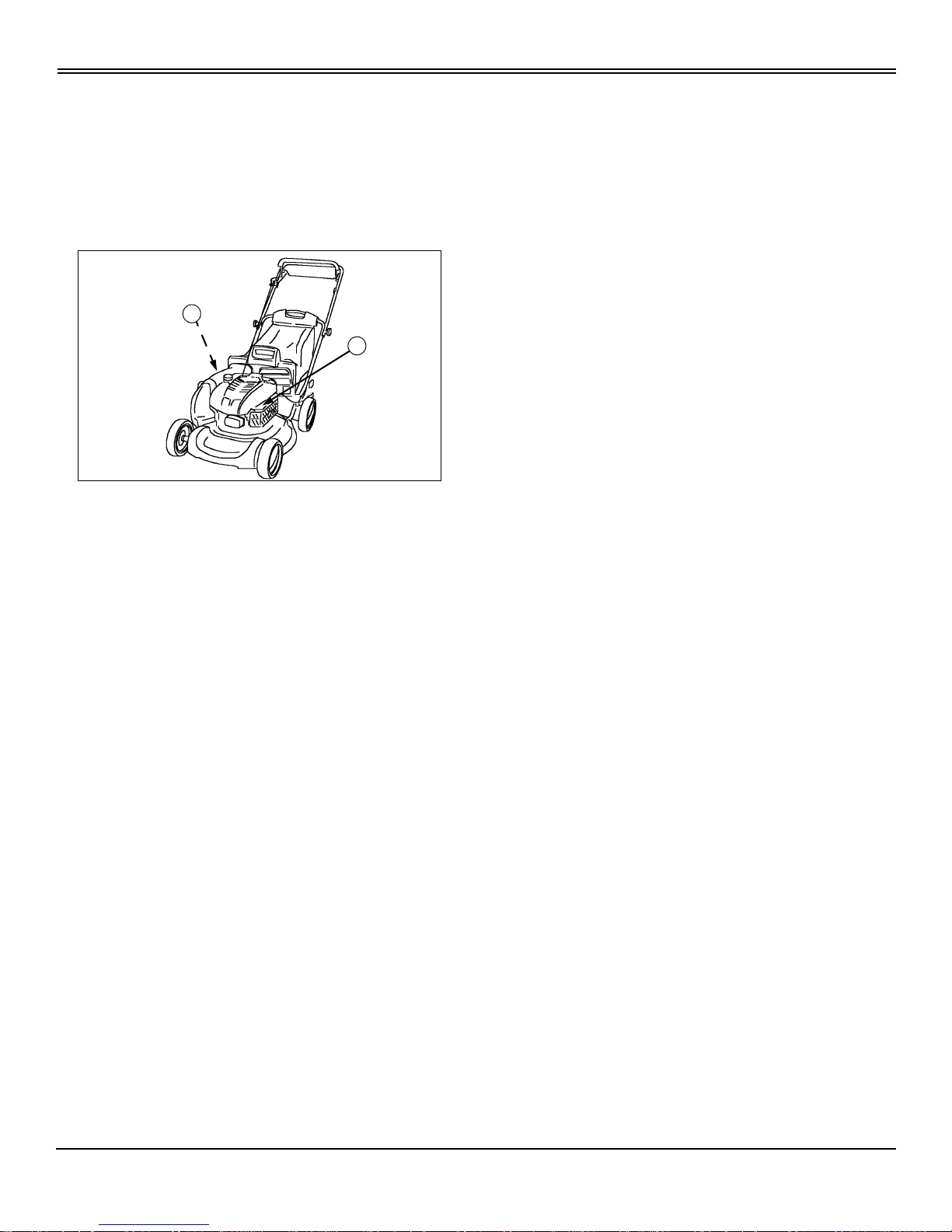
Record Identification Numbers
If youneedtocontact an authorizedScottsservicing dealer
for information on servicing, always provide the product
model and serial number.
You will need to locate the model and serial number for the
machine and fortheengineofyour machine and record the
information in the spaces provided below.
DATE OF PURCHASE:
_________________________________________
DEALER NAME:
_________________________________________
DEALER PHONE:
_________________________________________
PRODUCT IDENTIFICATION NUMBER (A):
__ __ __ __ __ __ __ __ __ __ __ __ __ __ __ __ __
ENGINE SERIAL NUMBER (B):
__ __ __ __ __ __ __ __ __ __ __ __ __ __ __ __ __
MX1575
B
A

Table of Contents
TABLE OF CONTENTS
All information, illustrations and
specifications in this manual are based
on the latest information at the time of
publication. The right is reserved to
make changes at any time without
notice.
COPYRIGHT© 1999
Deere & Co.
John Deere Worldwide Commercial and
Consumer Equipment Division
Horicon, WI
All rights reserved
Previous Editions
COPYRIGHT©
OMGC00390 K9 - English
Tableof Contents
Contents
Safety .....................................................................................................................................................................................1
Operating................................................................................................................................................................................5
Replacement Parts...............................................................................................................................................................12
Service Intervals...................................................................................................................................................................13
Service .................................................................................................................................................................................14
Troubleshooting....................................................................................................................................................................25
Storing Machine....................................................................................................................................................................27
Assembly..............................................................................................................................................................................29
Specifications .......................................................................................................................................................................33
Warranty...............................................................................................................................................................................35
Index.....................................................................................................................................................................................38
Safety - 1
SAFETY
Safety
Safety-Alert Symbol
Read and recognize safety information. Be alert to the
potential for personal injury when you see this safety-alert
symbol.
On your machine safety labels, the words DANGER,
WARNING, a nd CAUTION are used with this safety-alert
symbol. DANGER identifies the most serious hazards. In
this manual, the word CAUTION and this symbol call
attention to safety messages.
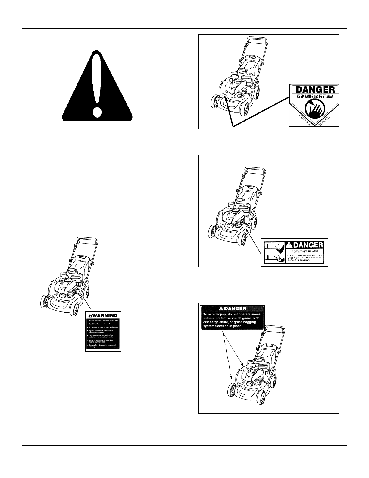
Machine Safety Labels
WARNING: AVOID SERIOUS INJURY OR DEATH
• Read the Owner’sManual.
• Go across slopes, not up and down.
• Do not mow when children or others are around.
• Look down and behind before and while mowing
backwards.
• Remove objects that could be thrown by the blade.
• Keep safety devices in place and working.
DANGER: KEEP HANDS AND FEET AWAY FROM
CUTTING BLADES
DANGER:ROTATINGBLADE
DO NOT PUT HANDS OR FEET UNDER OR INTO
MOWER WHEN ENGINE IS RUNNING
DANGER:
To avoid injury, do not operate mower without protective
Safety - 2
SAFETY
mulch guard, side discharge chute or grass bagging
system fastened in place.
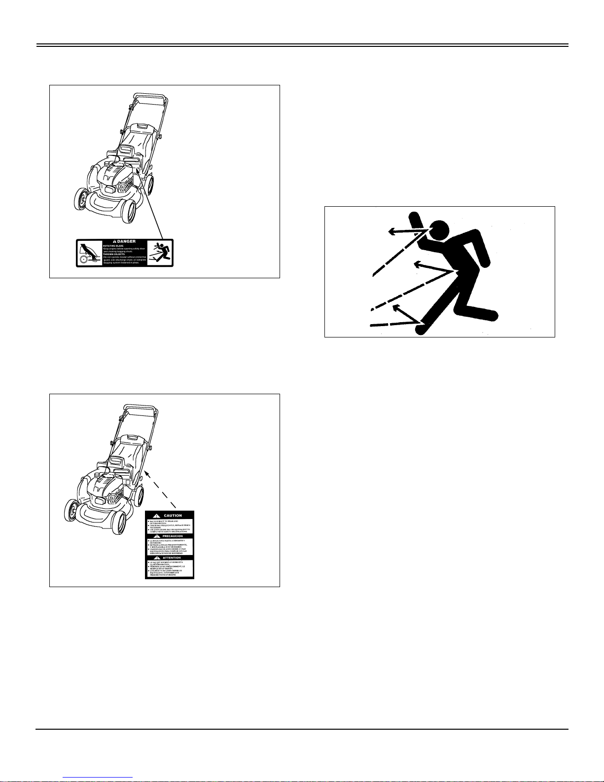
DANGER:ROTATINGBLADE
• Stop engine before opening safety door and clearing
bagging chute.
THROWN OBJECTS
• Do not operate mower without protective guard, side
discharge chute, or complete bagging system fastened in
place.
CAUTION
• Bag is subject to wear deterioration.
• Check bag frequently, replace when necessary.
• Use John Deere bag or equivalent to comply with safety
specifications.
Certification Label
The OPEI label on your mower indicates that this model
has been certified by an independent laboratory for
compliance with American National Standard B-71.1,
“Safety Specifications” for Power Lawn Mowers, Lawn and
Garden Tractors, and Lawn Tractors.
SAFETY
Operate Safely
• Inspect machine before you operate. Be sure hardware
is tight. Repair or replace damaged, badly worn, or missing
parts. Be sure proper guards, plates, grass catcher, or
other safety protective devices are in good condition and
fastened in place. Make any necessary adjustments before
you operate.
• Clear work area of objects that might be thrown. Keep
people and pets out of the work area. Stop machine if
anyone enters the area.
• If you hit an object, stop the machine and inspect it.
Make repairs before you operate. Keep machine properly
maintained and in good working order.
• DO NOT leave machine unattended when it is running.
• Only operate during daylight or with good artificial light.
• Be sure of footing. Be especially careful when you pull
machine backwards with the engine running.
• Mow across a hill - not up and down. Be careful when
you change direction on a slope. DO NOTmow excessively
steep slopes.
• DO NOT mow wet grass. Reduced traction could cause
you to slip.
• Keepafirmholdonthemachinehandle.
• DO NOT wear radio or music headphones while
operating the machine. Safe operation requires your full
attention.
• DO NOToperate mower if youare under the influence of
drugs or alcohol.
Safety - 3
SAFETY
Rotating Blades are Dangerous - Protect
Children and Prevent Accidents
PROTECT CHILDREN:
• Never assume that children will remain where you last
saw them. Children are attracted to mowing activity, stay
alert to the presence of children.
• Keep children in the house when you are operating the
machine.
• Turn machine off if a child enters the area.
• Use extra care when you come to blind corners, shrubs,
trees, or other objects that may block your vision.
• DO NOT let children or an untrained person operate the
machine.
HELP PREVENT SERIOUS OR FATAL ACCIDENTS:
• Be alert at all times, people especially children can
move quickly into the area before you know it.
• Stop the blade when crossing gravel drives, walks, or
roads.
• Shut off blades when you are not mowing.
• Keep hands, feet, and clothing away from rotating
blades.
Wear Appropriate Clothing
• Wear close fitting clothing and safety equipment
appropriate for the job.
• Do Not operate the equipmentwhen barefootor wearing
open sandals. Always wear substantial footwear.
• Loud noise can cause impairment or loss of hearing,
wearasuitableprotectivedevicesuchasearplugs.
Practice Safe Maintenance
• Understand service procedure before doing work. Keep
area clean and dry.
• Never lubricate, service, or adjust machine while it is
moving. Keep safety devices in place and in working
condition. Keep hardware tight.
• To prevent them from getting caught, keep hands, feet,
clothing, jewelry, and long hair awayfrom any moving parts.
• Beforeservicing machine,disengage all power and stop
the engine. Let engine cool.
• Securely support any machine elements that must be
raised for service work.
• Keep all parts in good condition and proper ly installed.
Fix damage immediately. Replace worn or broken parts.
Remove any buildup of grease, oil, or debris.
• Unauthorized modifications to the machine may impair
its function and safety.
Safety - 4
SAFETY
Avoid Injury from Contacting Blade
Before you unplug or adjust machine:
• STOP the engine.
• Wait for blade to STOP.
• Keep hands, feet and clothing away from blade when
engine is running.
Handling Waste Products
• Waste products, such as, used oil, fuel, and batteries,
can harm the environment and people.
• DO NOT use beverage containers for waste fluids someone may drink from them.
• See your local Recycling Center or authorized Scotts
servicing dealer to learn how to recycle or get rid of waste
products.
• A Material Safety Data Sheet (MSDS) provides specific
details on chemical products: physical and health hazards,
safety procedures, and emergency response techniques.
The seller of the chemical products used with your machine
is responsible for providing the MSDS for that product.
Handling Fuel Safely
Fuel and fuel vapors are highly flammable:
• DO NOT refuel machine while you smoke, when
machine is near an open flame or spar ks, or when engine
is running. STOP engine.
• Fill fuel tank outdoors.
• Prevent fires: clean oil, grease and dirt from machine.
Clean up spilled fuel immediately.
• Do not store machine with fuel in tank in a building
where fumes may reach an open flame or spark.
• Prevent fire and explosion caused by static electric
discharge. Use only non-metal, portable fuel containers
approved by the Underwriter’s Laboratory (U.L.) or the
American Society for Testing & Materials (ASTM). If using a
funnel, make sure it is plastic and has no screen or filter.
• Static electric discharge can ignite gasoline vaporsin an
ungrounded fuel container. Remove the fuel container from
the bed of a vehicle or the trunk of a car and place on the
ground away from the vehicle before filling. Keep nozzle in
contact with container opening while filling.
• When practical, remove equipment from trailers or truck
beds and refuel them on the ground. If this is not possible,
use a portable, plastic fuel container to refuel equipment on
atruckbedortrailer.
• DO NOT use METHANOL gasoline. METHANOL is
harmful to the environment and to your health.
Operating - 5
OPERATING
Operating
Engine Controls
A - Primer Bulb
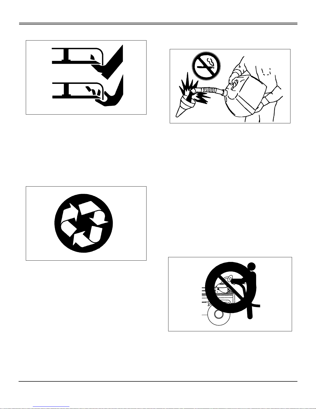
Handle Controls
A - Blade Control Lever
B - Traction Clutch Lever
C - Starter Handle
D - Travel Speed Lever (SP6213)
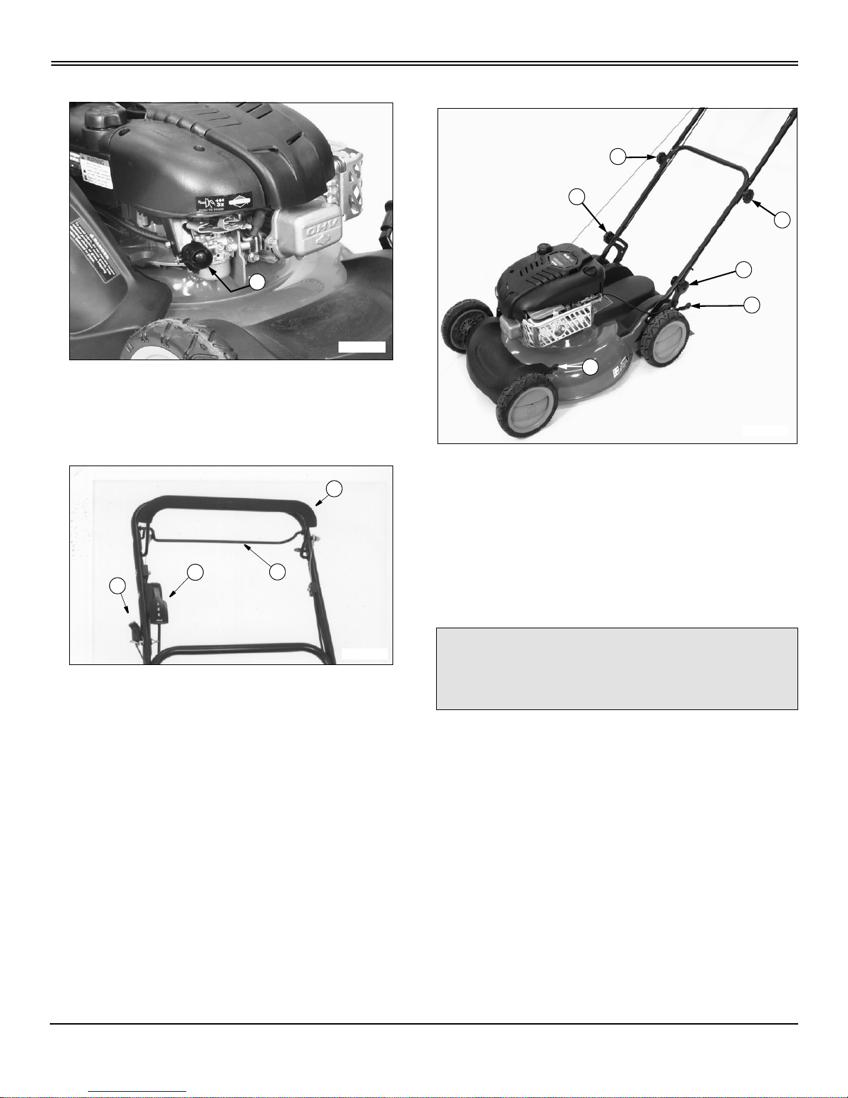
Handle and Cutting Height Controls
A - Fold Handle Knobs
B - Handle Height Knobs
C-CuttingHeightLevers
ADJUSTMENTS
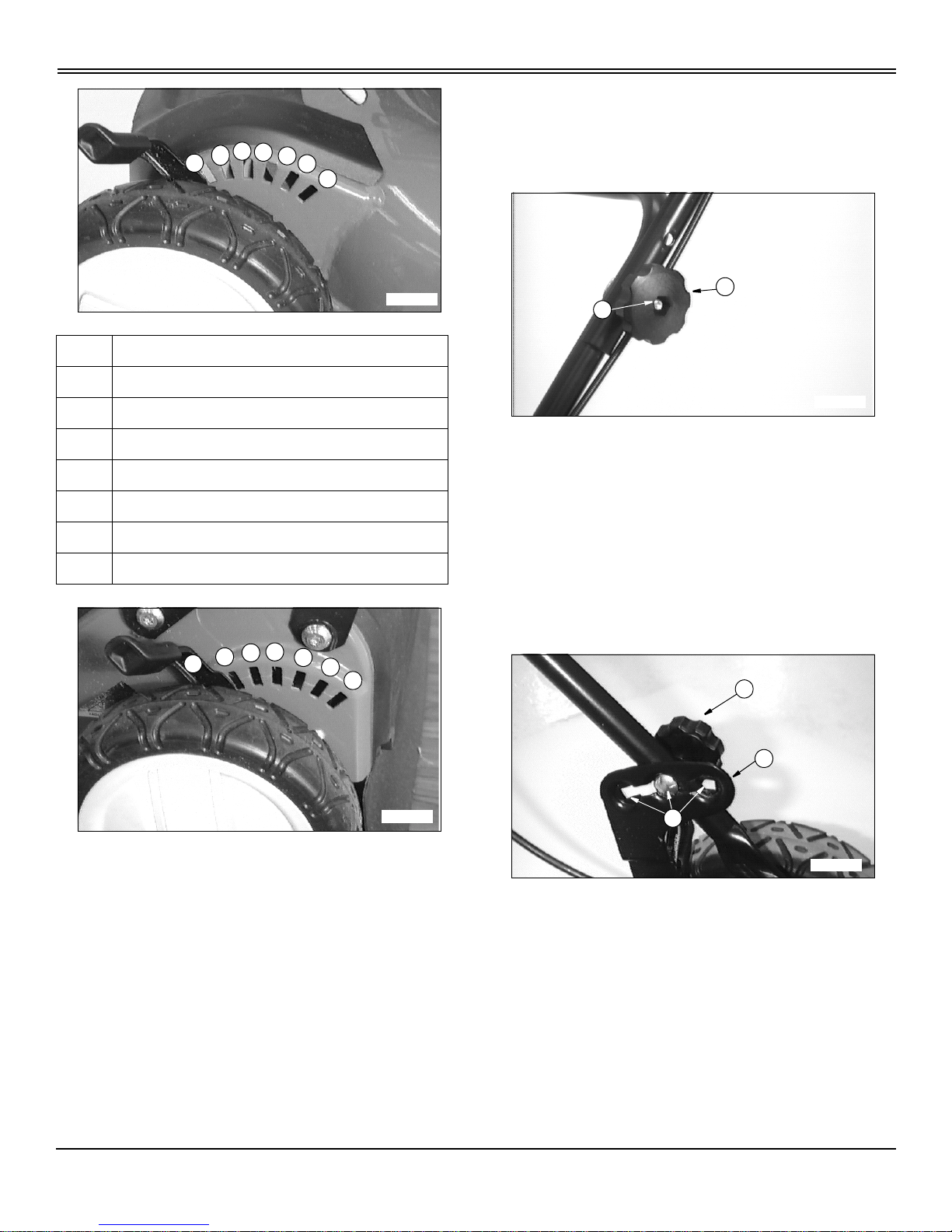
Adjusting Cutting Height
NOTE: Adjust both levers to same height except for
LOWEST cutting height (A). This adjustment improves
mulching performance at lowest cutting height:
• Put front wheel levers in 25 mm (1 in.) notch: First
rear notch.
• Put rear wheel levers in 38 mm (1-1/2 in.) notch:
Second rear notch.
To help move rear wheel lever:
1. Lift lower handlebar slightly with one hand to take some
weight off wheel.
2. Move height adjustment lever to desired position with
other hand.
MX1568
A
M93034
B
A
C
D
cCAUTION: Avoid injury! Before you adjust
cutting height:
STOP ENGINE.
M96540
B
A
A
B
C
C
Operating - 6
OPERATING
Adjusting Handle Height
Upper Handle:
NOTE: Upper handle height can be independently
adjusted to two positions.
1. Remove knob (A) and bolt (B) from each side of upper
handle.
2. Move handle to desired height.
3. Install bolt through matching holes in upper and lower
handles on each side.
4. Install and tighten knob (A).
Lower Handle:
NOTE: Lower handle height can be independently
adjusted to three positions.
1. Loosen knob (C) approximately 25 mm (1 in.) on each
side of handle.
NOTE: Carriage bolts must travel within slotted
adjustment brackets and come to rest within one of the
three height setting positions (E) before tightening.
2. Pivot handle to a desired height within slotted
adjustment bracket (D).
Key Cutting Height Adjustments In mm (Inches)
(A) 25mm(1in.)
(B) 38 mm (1-1/2 in.)
(C) 50mm(2in.)
(D) 64 mm (2-1/2 in.)
(E) 75mm(3in.)
(F) 90 mm (3-1/2 in.)
(G) 102 mm (4 in.)
A
B
C
D
E
F
G
M87101
A
B
C
D
E
F
G
M87102
A
B
M92146
M88835
C
D
E
Operating - 7
OPERATING
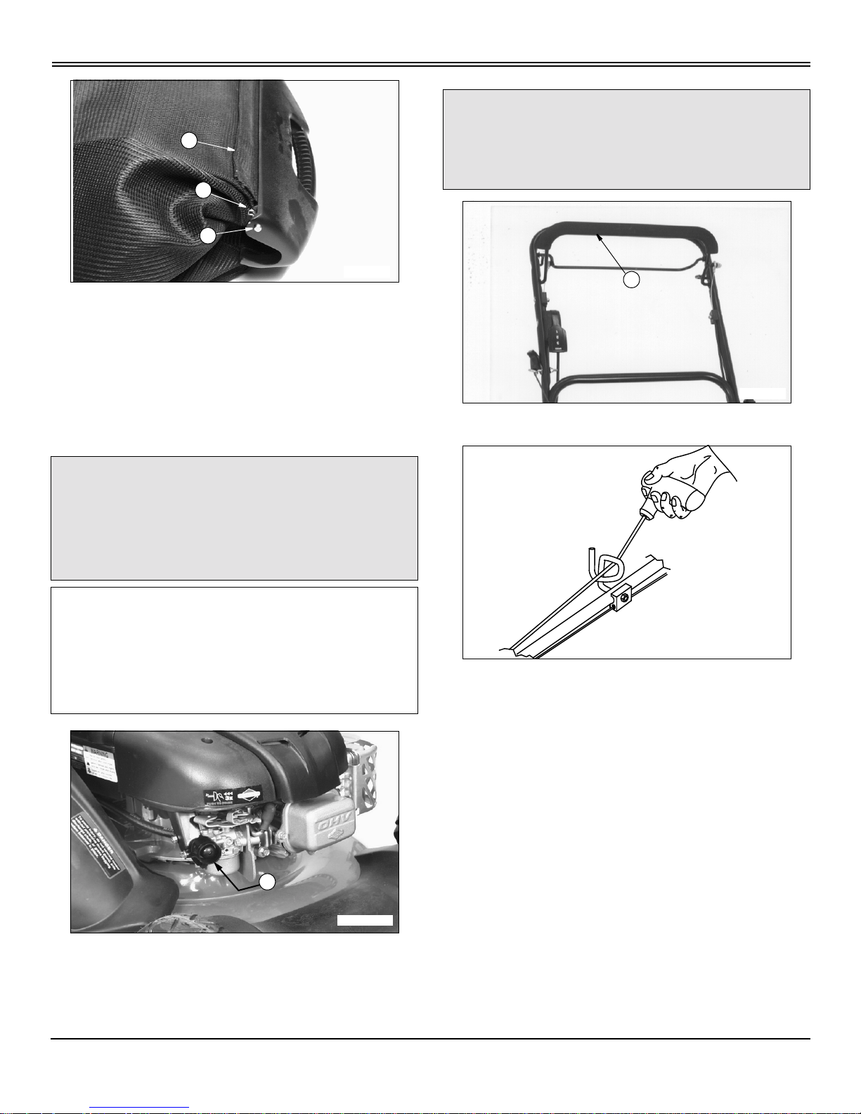
3. If bag preventslowering of handle, remove clip (F) to
remove rod (G). Remove rod from lower position (H) and
insert in upper position as shown to lengthen bag.
4. Tighten knob (C) on each side of handle.
Starting Engine
1. Primeenginebypressingprimerbulb(A):
• COLD Engine - 3 times
• WARM Engine - 1 or 2 times
2. Hold blade control lever (B) against handle.
3. Pull starter handle until you feel resistance. Then pull
fast and steady.
4. When engine starts, return rope slowly.
cCAUTION: Avoid injury! Engine exhaust fumes
can cause sickness or death.
Run engine only in a ventilated area.
If engine is run in an enclosed area, open doors
to bring in outside air.
IMPORTANT: Avoid damage! To help prevent
damage to recoil starter and band brake , do not start
engine:
• When blade is under load, such as, in heavy
grass.
• When blade control lever is released.
M96559
F
G
H
MX1568
A
cCAUTION: Avoid injury! WHEN ENGINE IS
RUNNING, BLADE IS TURNING.
Keep hands, feet and clothing away from the
blade.
B
M93034
M88828
Operating - 8
OPERATING
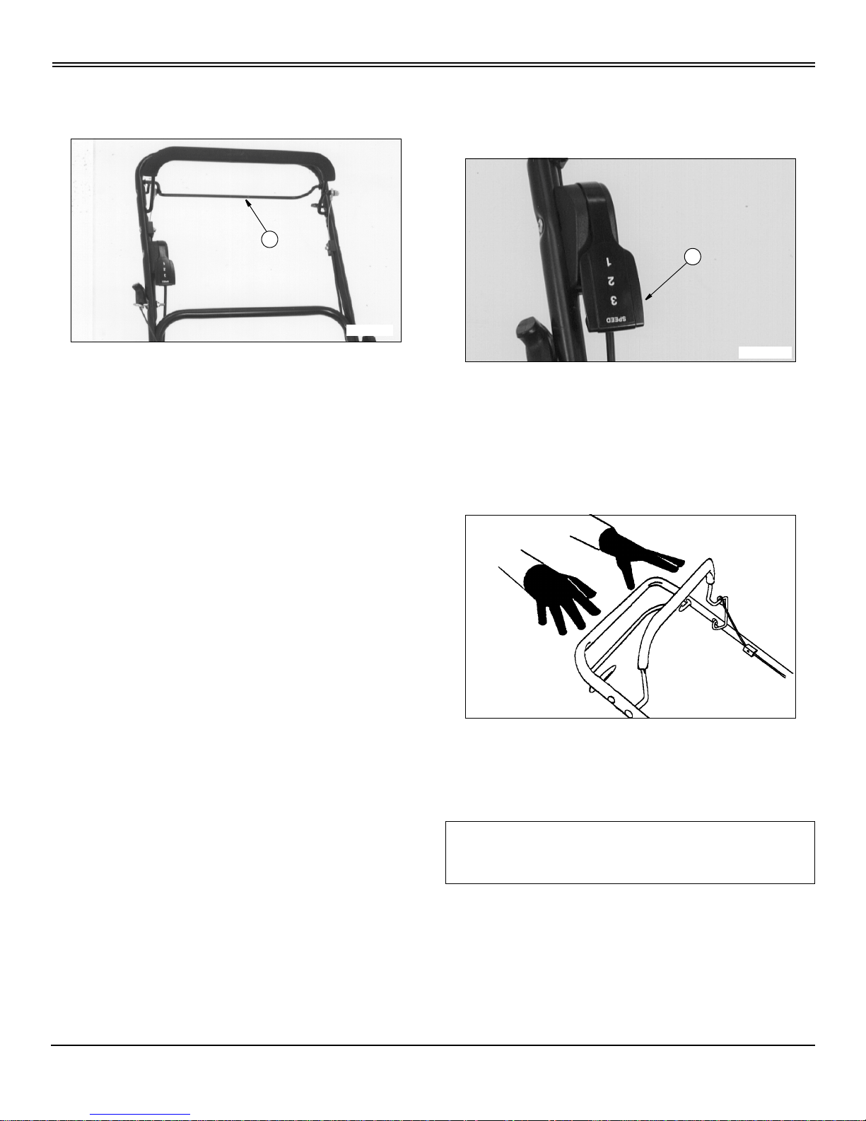
Forward Travel
To Travel Forward:
Pull and hold traction clutch lever (A) against upper handle.
To Stop Forward Travel:
NOTE: Rear wheels will make a clicking noise when
mower is pushed forward. This indicates that the drive
train is operating correctly.
Release lever (A). Release traction clutch lever before
turning the mower.
Travel Speeds
Travel speed: (SP6211)
• 1stGear:3.9km/h(2.4mph)
Travel speeds: (SP6213)
• 1stGear:3.1km/h(1.9mph)
• 2nd Gear: 3.9 km/h (2.4 mph)
• 3rd Gear: 5.0 km/h (3.1 mph)
To change travel speeds: (SP6213)
NOTE: Mower travel speed can be changed when the
traction clutch lever is engaged and the mower is
moving forward.
• Raise or lower speed control lever (A) to engage desired
gear.
Stopping Engine
Release handle and levers:
• Mower will stop.
• Blade will stop.
• Engine will stop.
M93034
A
IMPORTANT: Avoid damage! If blade does not stop
within 3 seconds after you release blade stop lever,
see your authorized Scotts servicing dealer.
M93035
A
M73293a
Operating - 9
OPERATING
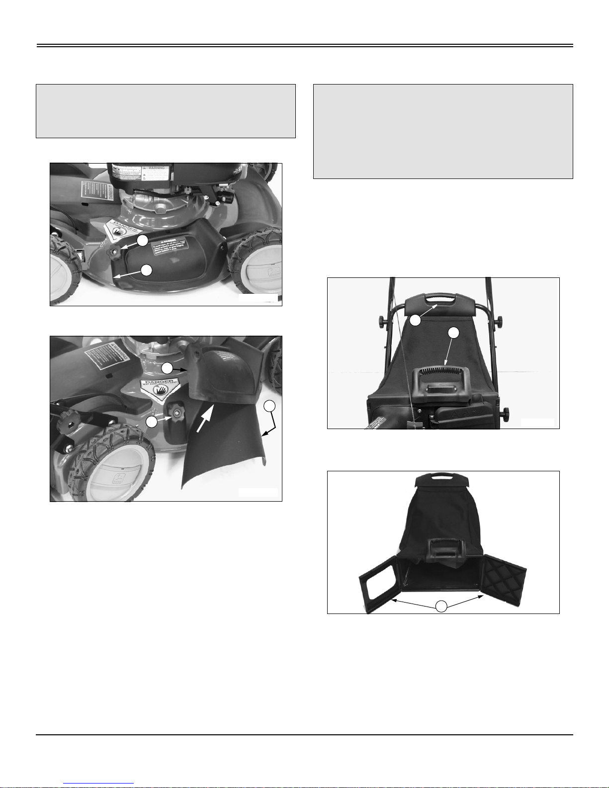
Using Side Discharge Chute
1. Release blade control lever to stop engine.
2. Remove mulch guard knob (A).
3. Lift and hold spring loaded mulch guard (B) up.
4. Install side discharge chute (C).
• Slide side discharge chute under mulch guard
mounting bracket.
• Lower mulch guard.
• Reinstall and tighten knob (A).
Using Grass Bag
NOTE: Bag may wear and deteriorate. Check condition
of bag often. Use a John Deere bag or equivalent to
comply with safety specifications.
1. Release blade control lever to stop engine.
2. Grasp handle (A) and handle (B) from left side of mower.
Lift bag off mower.
3. Lower front of bag. Raise rear of bag grasping handle
(A) and handle (B).
4. Allow doors (C) to swingopen. Shake contents of bag to
empty out.
Mowing Tips
Beforebeginningtomow,besuredeckislevelandproper
cutting height is selected.
cCAUTION:Avoidinjury! DO NOT operate mower
unless grass bag assembly, side discharge
chute or mulch guard is in place.
MX1566
A
B
MX1570
B
C
A
cCAUTION: Avoidinjury! DO NOT operate mower
unless mulch guard, side discharge chute or
grass bag and bagging chute are in place.
BaggingchuteMUSTberemovedandmulch
guard secured in place when grass bag is not
being used.
M96549
B
A
M96558
C

Operating - 10
OPERATING
When you mow an area for the first time, travel SLOW and
cut HIGH so you can:
• Learn the terrain.
• Learn the best mowing pattern.
• Help prevent hitting objects hidden in the grass.
Try to m ow grass only when it is dry: Wet grass may plug
mower and leave a trail of grass clumps.
Use a travel speed that fits the conditions:
• Travel SLOW when you mow thick, tall grass.
• FAST travel or sharp turns may produce stripes or
uneven cut. Slow down. Short, fast turns may scuff ground
and pull grass out by the roots.
• Travel at MODERATE speed when youmow a thin stand
of grass.
Mow often enough so you cut only 1/3 of grass blade in one
mowing. Cutting grass too short may kill grass and let
weeds grow easily.
Aerate lawn to help stimulate soil organisms and root
growth.
To Avoid Scalping
• Pay attention to the way you mow: scalping can be
eliminated.
• If mower scalps easily, cutting height may be too low for
ground conditions–especially on lawns with many small
mounds and r idges.
• Mow over ridges and through shallow ditches straighton, not at an angle.
Keep blade sharp: A dull blade will tear grass; tips of grass
will then turn brown.
Check lawn regularly for uneven cut. If cut is uneven:
• Mower may not be level. Adjust cutting height levers.
Bagging Tips
For best performance, bagger needs good airflow. To help
increase airflow:
• Keep underside of deck and chute clean.
• Cut grass high.
• Clean bag often with water from garden hose, from
outsidetoinsideofbag.Letbagdrybeforeuse.
When bag is full:
• Mower may leave a trail of clippings.
• Clippings may blow out from under deck.
• Top of bag will deflate.
Bagging and Composting
Many communities will no longer haul lawn clippings and
leaves to landfills. Bagging and composting clippings and
leaves is one way to solve this problem.
Clippings from grass bag may also be used as mulch, or
sheet compost, between garden rows and around trees
and shrubs. This mulch will:
• Keep weeds from growing.
• Help soil keep moisture.
• Add nutrients to soil as it decays.
• Help keep soil temperature down during hot weather.
You may compost clippings and leaves in various ways.
See garden magazines or clubs for information, or go to
your local library for help.
Finished compost is crumbly. It is rich in soil nutrients, and
can be spread on your lawn. Compost may also be worked
into soil. It adds humus to soil and improves soil texture,
making soil looser and easier to work.
Mulching Tips
Advantages:
• You d o not have to rake or bag grass or leaves.
• Lawn holds moisture better during dry weather.
• Soil temperatures stay down during hot weather.
• Mulch adds nutrients to soil, and reduces need for
fertilizer.
Mulching does not make thatch. Frequentshallow watering
and fertilizer application produce thatch from roots that
grow close to surface.
Be careful when you mulch leaves in Fall. Grass needs
IMPORTANT: Avoid damage! DO NOT leave
clippings in bag:
• Moisture may damage bag.
• Damp clippings are a fire hazard.

Operating - 11
OPERATING
sunlight in Fall to help store food for Winter. A thick layer of
mulched leaves can prevent sunlight from getting to grass
andsmotherit.Youmayhavetomowwithgrassbagto
remove this layer.
Mulch leaves only when they are dr y.
Mulching wet or damp grass or leaves may cause
problems:
• Clippings and leaves may build up on the underside of
the mower deck.
• Cut grass and leaves may form clumps.
• Leaves may not be cut into small bits.
• Engine will work harder and use more fuel.
• Clean underside of mower deck after mulching wet or
damp grass.
If possible cut only top 1/3 of grass at a time.
Useadifferentmowingpatterneachtimeyoumow.
Overlap mowing paths 50–100 mm (2–4 in.) instead of
cutting a full swath with each pass.
Operate mower at a slower ground speed. Mulching takes
more power.
Keep blade sharp. Check it often.
Keep underside of deck clean.
If clippings are not dispersed evenly or quality of cut is
marginal, raise cutting height one or more positions.
After Mowing
• STOP engine. Let it cool. This will help prevent starting
afirewhenyoustorethemower.
• Remove and shake bag to remove all clippings. This will
help to prevent deterioration of bag and starting a fire.
• Clean top of deck, engine, and chute with brush or
compressed air,if possible. This will help to prevent buildup
andstartingafire.
• Spray under deck with water under pressure to remove
corrosive lawn chemicals and buildup.
• Put mower in safe storage.

Replacement Parts - 12
REPLACEMENT PARTS
ReplacementParts
Service Literature
If you would like a copy of the Parts Catalog or Technical
Manual for this machine call:
• U.S. & Canada: 1-800-522-7448.
• All Other Regions: Your John Deere dealer.
John Deere Quality
We recommend John Deere quality parts and lubricants,
available at your authorized Scotts servicing dealer.
Part numbers may change, use part numbers listed below
when you order. If a number changes, your dealer will have
the latest number.
When you order parts, your authorized Scotts servicing
dealer needs your machine product identification number
and engine serial number. These are the numbers that you
have recorded in the Product Identification section of this
manual.
Touch-up paint is available in 340 grams (12 oz.) aerosol
cans. Scotts Orange (part number: TY24745).
(Part numbers are subject to change without notice. Part
Numbers may be different outside the U.S.A.)
ITEM PART NUMBER
Air Cleaner:
• Foam Pre-cleaner
• Paper Element
GC00440
GC00441
Traction Drive Belt
• SP6211
• SP6213
GC00073
GC00081
Standard Mulch Blade GC00344
Bagging Blade
(Optional)
GC00175
Spark Plug Champion RC12YC
SAE 30, Engine Oil (1 quart) TY22070

Service Intervals - 13
SERVICE INTERVALS
ServiceIntervals
Service Intervals
Please use the following timetables to perform routine
maintenance on your machine. Service procedures
included in this manual but not on this chart are to be
performed on an as needed basis.
Before Each Use
• Check oil level.
After Each Use
• Clean the mower.
First 5 Hour
• Change engine oil. (Break-in)
• Lubricate mower axles.
• Lubricate drive shaft hub bushings.
Every 25 Hours Or Once A Year
• Tighten blade bolt.
• Clean or replace air cleaner paper element.
• Clean and gap spark plug.
• Clean belt and transmission area.
• Change engine oil.
• Lubricate mower axles.
• Lubricate drive shaft hub bushings.
IMPORTANT: Avoid damage! If you operate mower
in extreme heat, dust or other severe conditions,
service more often than shown below.

Service - 14
SERVICE
Service
Engine Warranty Maintenance Statement
Maintenance,repair,or replacementof the emissioncontrol
devices and systems on this engine, which are being done
at the customers expense, may be performed by any
nonroad engine repair establishment or individual.
Warrantyrepairs must be performed by an authorized
Scotts servicing dealer.
Adjusting Carburetor
NOTE: Carburetor is calibrated by the engine
manufacturer and should not require any adjustments.
NOTE: If engine is operated at altitudes above 1829 m
(6,000 ft), some carburetors may require a special high
altitude main jet. See your authorized Scotts servicing
dealer.
If engine is hard to start or runs rough, check the
TROUBLESHOOTING section of this manual.
After performing the checks in the troubleshooting section
and your engine is still not performing correctly, contact
your authorized Scotts servicing dealer.
Avoid Fumes
Engine Oil
Use oil viscosity based on the expected air temperature
range during the period between oil changes.
The following John D eere oils are preferred:
• TORQ-GARD SUPREME® (SAE 30)
The following John Deere oils are also recommended,
based on their specified temperature range:
• TURF-GARD® (SAE 10W-30)
• PLUS-4® (SAE 10W-30)
Other oils may be used if above John Deere oil is not
available, provided they meet one of the following
specifications:
• SAE 10W-30–API Service Classification SG or higher
• SAE 30–API Service Classification SC or higher
Checking Engine Oil Level
1. Stop engine. Put mower on a level surface.
cCAUTION: Avoid injury! Engine exhaust fumes
can cause sickness or death:
• If it is necessary to run an engine in an
enclosed area, use an exhaust pipe extension
to remove the fumes.
• Always try to work in a well ventilated area.
cCAUTION: Avoid injury! Before you check or
add oil, STOP engine. Let it cool.
AIR TEMPERATURE
SAE 30
SAE10W-30
SAE 5W-30
122° F
104° F
86° F
68° F
50° F
32° F
14° F
-4° F
-22° F
-40° F
50° C
40° C
30° C
20° C
10° C
0° C
-10° C
-20° C
-30° C
-40° C
Service - 15
SERVICE
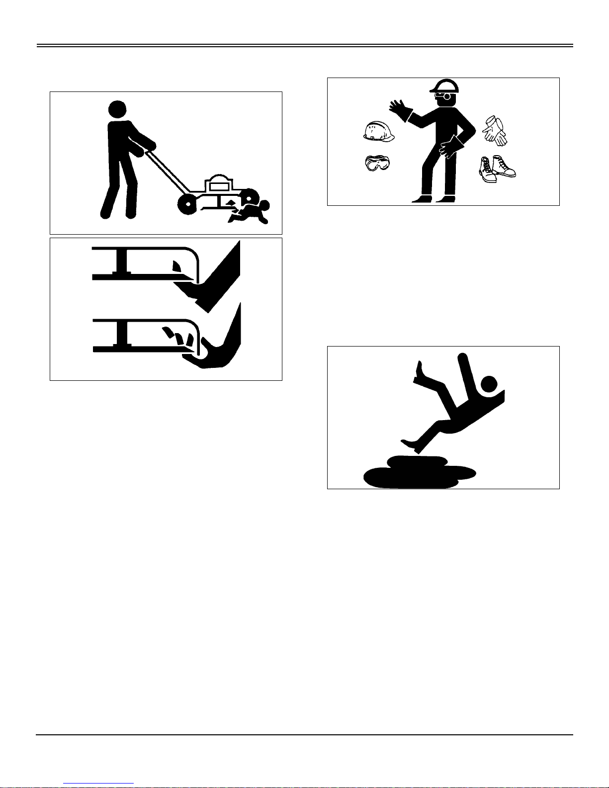
2. Turn oil dipstick (A) 1/4 turn counterclockwise. Remove
dipstickandwipeitwithacleancloth.
3. Install dipstick. Turn dipstick 1/4 turn clockwise and
tighten.
4. Remove dipstick. Check oil level. Oil level MUST BE
between ADD and FULL marks. If not, pour oil into dipstick
tube to bring level to FULL mark (B).
5. Install and tighten dipstick.
Changing Engine Oil
NOTE: Two different methods can be used for
changing the engine oil. Both options are acceptable
service procedures based on customer preference.
TO CHANGE ENGINE OIL FROM THE TOP:
1. Park mower on a level surface.
2. Run engine until fuel tank is empty or near empty.
3. Stop engine and disconnect spark plug wire.
4. Turn oil dipstick (A) 1/4 turn left and remove from the
filler tube.
5. Insert plastic drain tube (B) firmly inside filler tube
opening.
6. Place a drain pan on the left side of the mower.
IMPORTANT: Avoid damage! If oil level is below
the ADD mark, DO NOT run the engine.
cCAUTION: Avoid injury!
• Used oil may harm environment and people
if it is dumped on the ground or into a drain or a
body of water. Call your local Recycling Center
or authorized Scotts servicing dealer to learn
how to recycle used oil.
• Engine may be hot, use caution to avoid
burns to the hands.
MX1567
A
B
M61459
IMPORTANT: Avoid damage!
• Change oil after first 5 hours of operation.
• Change oil while engine is warm.
• If mower is not operated 25 hours during the
mowing season, change oil before storing mower.
• Help prevent air cleaner damage and hard
starting, turn mower onto the LEFT side when
servicing.
MX1567
A
B
M87111d

Service - 16
SERVICE
7. Turn mower onto its LEFT SIDE.
8. Allow engine oil to drain from the dipstick filler tube
location into the drain pan.
9. After oil has drained, return mower to an upright
position.
10.Remove plastic drain tube. Clean area around filler tube.
11.Add 0.47 L (16 oz) oil through dipstick filler tube.
12.Install dipstick. Turn dipstick 1/4 turn right to tighten.
13.Removedipstick. Check oil level. Add oil to FULL mark if
necessary.
14.Install and tighten dipstick.
15.Connect spark plug wire.
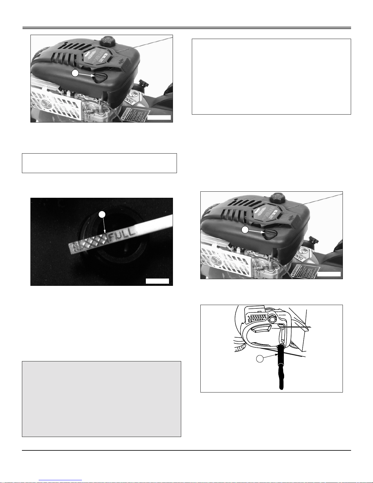
TO CHANGE ENGINE OIL FROM THE BOTTOM:
1. Stop engine and disconnect spark plug wire.
2. Raise cutting height adjustment levers (A) to the highest
cutting position. (See Adjusting Cutting Height in the
Operating section.) Elevate entire mower an additional 102
mm - 203mm (4-8 in.) using wooden blocks or bricks.
3. Place a drain pan under the mower.
4. Remove drain plug (B) from underside of mower using a
3/8 in. square drive.
5. After oil has drained, clean and install drain plug.
6. Turn oil dipstick 1/4 turn to the left. Remove dipstick.
7. Add 0.47 L (16 oz) oil through dipstick filler tube.
8. Install dipstick. Turn dipstick 1/4 tur n right to tighten.
9. Removedipstick. Check oil level. Add oil to FULL mark if
necessary.
10.Install and tighten dipstick.
11.Lower mower.
12.Return cutting height adjustment levers to a desirable
cutting height.
13.Connect spark plug wire.
Cleaning and Replacing Air Cleaner Element
1. Stop engine and disconnect spark plug wire.
cCAUTION: Avoid injury! Fuel is highly
flammable. Prevent fuel from contacting hot
surfaces: DO NOT drain fuel tank. Run engine
until fuel tank is very low or empty before
turning mower on side to change oil.
cCAUTION: Avoid injury! Be careful of s harp
edges on mower blades. Wear gloves when
working under deck.
A
A
cCAUTION: Avoid injury! Before you work on
engine:
• STOP engine. Let it cool.
IMPORTANT: Avoid damage!
• If operation of the mower is done in very dusty
conditions, clean element often.
• Replace paper element when engine starts hard,
begins to lose power, or runs rough.
• DO NOT use a damaged element. Replace when
necessary.
• DO NOT run engine without element.
M87113
B

Service - 17
SERVICE
2. Clean area around cover (A).
3. Loosen screws (B) and remove cover.
NOTE: If precleaner or paper element has a break or is
damaged, replace it.
4. If precleaner (C) is dirty, carefully remove paper element
and precleaner. Remove precleaner from element (D).
5. If paper element is excessively dirty, replace it with a
new element.
6. If precleaner is dirty, clean it as follows:
• Wash it in a solution of warm water and liquid
detergent. DO NOT wash paper element.
• Rinse precleaner.
• Allow precleaner to air dry.
7. Install precleaner on paper element and install air
cleaner.
8. Install air cleaner cover and tighten screws.
Cleaning and Gapping Spark Plug
1. Disconnect spark plug wire (A). Remove plug (B).
2. Carefully wire brush carbon from plug. Do not clean it
with abrasives in a machine.
3. Inspect plug for damage. Replace damaged plug.
4. Adjustgapto0.51mm(0.020in.).
5. Install and tighten plug to 20 N•m(15lb-ft).
6. Connect spark plug wire.
Cleaning Engine Cooling Fins
Clean fins (A) with a brush, rag, or compressed air.
Also, blow compressed air under the shroud.
cCAUTION: Avoid injury! Before you remove
plug:
• STOP engine. Let it cool.
MX1571
A
B
MX1572
D
C
cCAUTION: Avoid injury! Wear eye protection to
guard against flying debris.
IMPORTANT: Avoid damage! Keep fins clean or
engine may overheat.
MX1573
B
A
MX1574
A
Service - 18
SERVICE
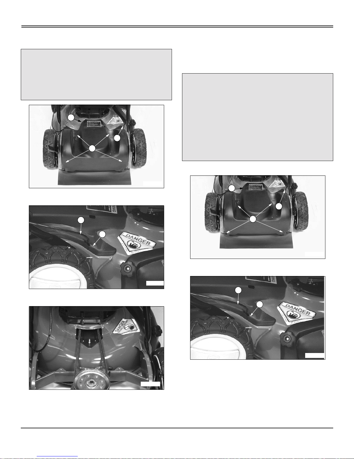
Cleaning Drive Belt and Transmission Area
1. Remove hardware (A) and belt shield (B).
2. Remove control cables (C) from belt shield notch (D).
3. Remove clippings from belt area and top of the
transmission.
4. Slide control cable into belt shield notch.
5. Install belt shield.
Checking and Replacing Drive Belt
1. Stop engine and disconnect spark plug wire.
2. Remove hardware (A) and belt shield (B).
3. Remove control cables (C) from belt shield notch (D).
cCAUTION: Avoid injury! Before you remove
shield:
• STOP engine. Let it cool.
• DO NOToperate mower without belt shield in
place.
M96556
A
B
C
M93055
D
C
M96557
cCAUTION: Avoid injury! Before removing belt
shield:
• Stop engine and wait for all moving parts to
stop.
• Prevent burns by allowing engine to cool.
• Disconnect spark plug wire.
• Wear protective gloves when service is
performed within the mower blade area.
• DO NOT operate mower without belt shield.
M96556
A
B
C
M93055
D
C
Service - 19
SERVICE
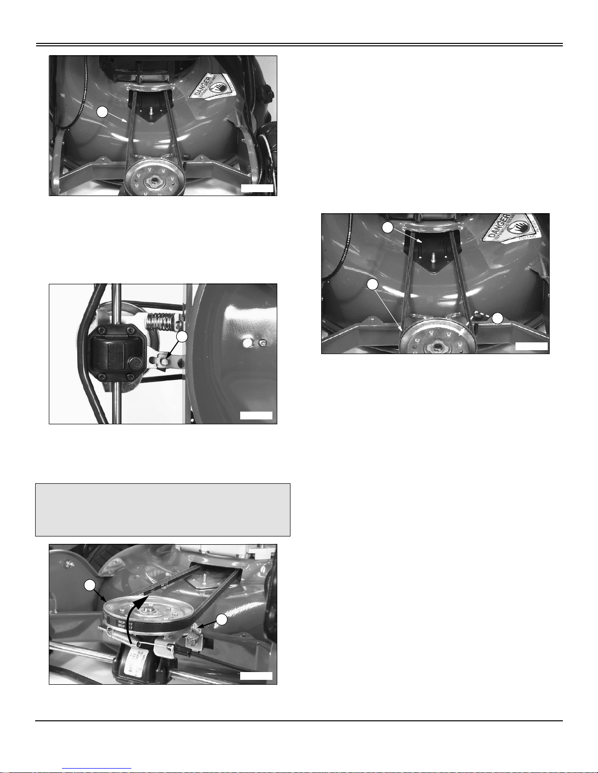
4. Inspect belt (E) for excessive wear or damage.
TO REPLACE DRIVE BELT:
NOTE: On model SP6211 only,the anti-rotation bracket
must be removed prior to pushing the drive sheave
forwardtoremovethedrivebelt.
Picture Note: View is from underside of differential.
1. Remove cap screw (F) and anti-rotation bracket.
2. Pushdrivesheave(G)forwardtorelievespringtension
on belt.
NOTE: Tension spring (H) may come loose w hen belt
is removed.
3. Remove belt from drive sheave.
4. Move belt into underside of mower deck.
5. Turn mower onto its LEFT SIDE.
6. Remove mower blade. (See Check Blade in this
section.)
7. Remove drive belt from blade sheave.
8. Install new drive belt to blade sheave.
9. Insert belt through deck opening (I).
10.Install tension spring (H) if removed.
11.Check that drive belt is installed on engine sheave.
12.Push drive sheave (J) forward and install belt to sheave.
13.Install anti-rotation bracket and secure with cap screw.
14.Install mower blade.
• Tighten mower blade bolt to 75 N•m(55lb-ft).
15.Lower mower.
16.Slide control cables into belt shield notch.
17.Install belt shield and connect spark plug wire.
cCAUTION: Avoid injury! Wear protective
eyewearwhen removingbelt from drive sheave.
Tension spring may come loose.
M96557
E
MX1578
F
MX1576
H
G
M96554
J
H
I

Service - 20
SERVICE
Transmission Cable Adjustment—SP6213
1. Stop engine and disconnect spark plug wire.
2. Remove hardware (A) and belt shield (B).
NOTE: Transmission cable adjustment can be
performed without removing belt and pulley. The belt
and pulley have been removed for clarity of pictures.
3. Remove control cables (C) from belt shield notch (D).
4. Push drive sheave (E) forward to relieve spring tension
on belt and remove drive belt (F).
5. Remove E-clip (G) and drive sheave.
6. Measure the clutch spring length (H) in the relaxed
position. Record this value.
7. Engage the transmission bail (at handle bar) and
measure the spring length in the extended position (I).
The spring extension length (the difference between A and
B measurements) must be 10 mm (0.390 in.).
cCAUTION: Avoid injury! Before removing belt
shield:
• Stop engine and wait for all moving parts to
stop.
• Prevent burns by allowing engine to cool.
• Disconnect spark plug wire.
• Wear protective gloves when service is
performed within the mower blade area.
• DO NOT operate mower without belt shield.
cCAUTION: Avoid injury! Wear protective eye
wear when removing belt from drive sheave.
Tension spring may come loose.
M96556
A
B
C
M93055
D
C
MX1577
F
E
G
M96828
H
M96831
I

Service - 21
SERVICE
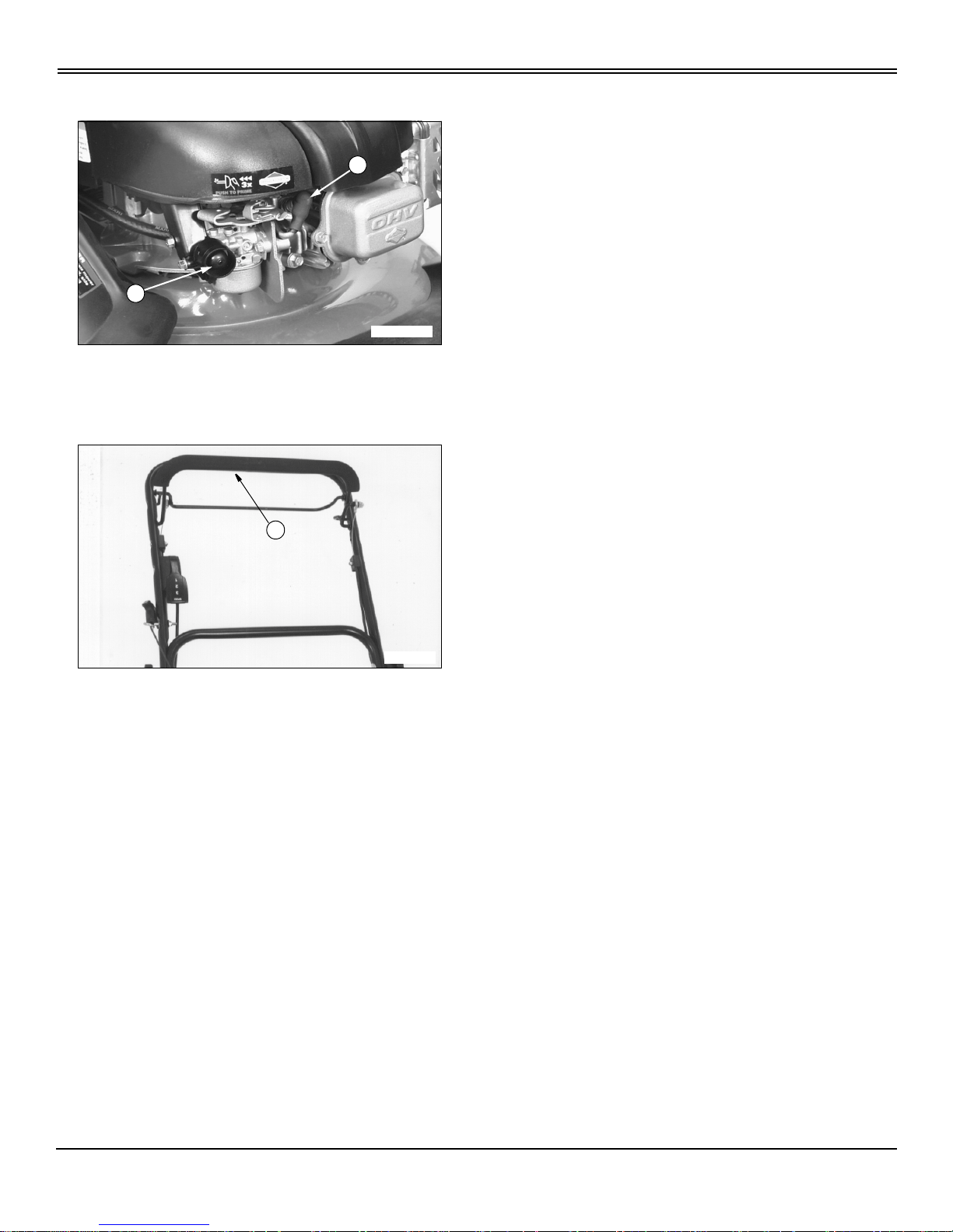
8. To adjust spring extension, use an 8 mm wrench, loosen
(do not remove) the cable mount bracket capscrews (J).
NOTE: For transmission clutch to operate properly,
there must be a certain amount of spring pressure
engaging the cones or the transmission will slip and
NOT drive the wheels.
9. Slidebracket(K)therequireddistancetoobtainthe10
mm (0.390 in.) spring extension length (difference between
thelengthoftherelaxedspringandthelengthofthe
extended spring). Tighten capscrews.
10.Repeat steps 6 and 7 to verify the 10 mm (0.390 in.)
spring extension length.
11.Install drive sheave and E-clip.
12.Check that drive belt is installed on engine sheave.
13.Install transmission drive belt.
14.Install cables through notch in cover.
15.Install cover and secure with two bolts and two bolts and
nuts. Make sure shield is installed with cover.
16.Start engine and verify the transmission is operating
properly.
NOTE: Make sure the transmission immediately
disengages when the bail is released.
17.If transmission does not disengage when bail is
released, reduce spring extension length, and verify
transmission is operating properly.
Lubricate Drive Shaft Hub Bushings
1. Remove hardware (A) and belt shield (B).
2. Remove control cable (C) from belt shield notch (D).
3. Tilt mower slightly to one side. Lubricate driveshaft hub
bushing (E) with a few drops of light weight motor oil.
Repeat procedure for other side.
4. Slide control cables (C) into belt shield notch (D).
5. Install belt shield.
Lubricate Mower Axles
1. Tip mower to one side to elevate mower wheels slightly
off the ground. Use a wood block to keep side of mowerin a
M96827
J
M96827
K
M96556
A
B
C
M93055
D
C
M93048
E

Service - 22
SERVICE
raised position.
2. Remove plastic hubcaps (A).
• Use a screwdriver in slot (B) to pry the hubcap from
each wheel.
3. Remove locknut (C) and washer (D).
4. Remove wheel from each axle.
5. Apply a light coating of grease to each a xle (E).
6. Install wheels, hardware and hubcaps.
7. Lower mower.
8. Repeat procedure on other side of mower.
Check Blade
NOTE: Sharpened edges on blade tips must face
upward when installing blade.
CHECK BLADE:
• Replace damaged blade.
• Tighten Bolt (A) to 75 N•m(55lb-ft).
• Sharpen dull blade. (See Sharpening Blade in this
section.)
TO REMOVE BLAD E:
• Remove bolt (A), washer (B), and blade.
Sharpening Blade
Sharpen blade with grinder, hand file or electric blade
M93049
A
B
M93051
C
D
E
M93050
cCAUTION: Avoid injury! Ser v ice blade safely:
• STOP engine. Let it cool.
• Disconnect spark plug wire.
• Wear gloves or wrap blade with a rag.
IMPORTANT: Avoid damage!
Turn mower on its LEFT SIDE to help prevent air
cleaner damage and hard starting.
cCAUTION: Avoid injury! Wear gloves and
goggles when sharpening, balancing or
installing blade.
IMPORTANT: Avoid damage! Balance blade after
you sharpen it. An unbalanced blade may cause
excessive vibration.
M87085
B
A

Service - 23
SERVICE
sharpener.
Keep original bevel (A) when you grind. Blade should have
0.40 mm (1/64 in.) cutting edge (B).
Balance and Install Blade
1. Cleanblade.Putitonanailinviseoronawall.Heavy
end of blade will drop. Grind bevel of heavy end. Do not
change bevel.
2. Install blade, washer, and bolt.
3. Tightenboltto75N•m (55 lb-ft).
Filling Fuel Tank
Use regular grade 87 octane unleaded fuel.
Add John Deere fuel stabilizer to fuel before using it in your
machine to preventengine damage due to stale fuel. Follow
directions on stabilizer container.
1. STOP engine. If engine is hot let it cool several minutes
before you add fuel.
2. Remove grass clippings and other trash from tank area.
3. Remove fuel tank cap (A).
4. Fill tank with fuel only to bottom of filler neck.
5. Install fuel tank cap.
A
B
M61830
M61524
IMPORTANT: Avoid damage! Dirt and water in fuel
are major causes of engine performance problems.
Prevent dirt and debris from entering the fuel tank
when filling.
• Use a non-metallic funnel with a non-metallic
mesh strainer when filling fuel containers.
• Use a non-metallic funnel with a non-metallic
mesh strainer when filling the fuel tank.
• Fillthefueltankattheendofeachday’s
operation to keep condensation out of the fuel tank.
• Use clean, fresh, stabilized fuel.
Fueltankcapacityis1.5L(1.6qt).
MX1571
A

Service - 24
SERVICE
Cleaning Fuel Cap Vent
1. Check two vents (A) under metal ring of fuel cap and
vent in top, center of cap.
2. Clean cap and vents in nonflammable solvent.Allow cap
to dry.
3. Install the cap.
A
M73283

Troubleshooting - 25
TROUBLESHOOTING
Troubleshooting
Using Troubleshooting Chart
If you are experiencing a problem that is not listed in this
chart, see your authorized Scotts servicing dealer.
Whenyouhavecheckedallthepossiblecauseslistedand
you are still experiencing the problem, see your authorized
Scotts servicing dealer.
IF CHECK
Engine Will Not Start • Prime engine, (Cold - three times, Warm - 1 or 2 times)
• Fuel tank is empty.
• Stale or dirty fuel.
• Disconnected or dirty spark plug.
Engine Starts Hard Or Loses Power • Dirty fuel tank cap vents.
• Stale or dirty fuel.
• Dirty air cleaner element.
• Disconnected or dirty spark plug.
Engine Runs Rough • Carburetor needs to be cleaned.
• Disconnected or dirty spark plug.
• Dirty air cleaner element.
• Dirty cooling fins.
Engine Overheats • Dirty blower housing and cooling fins.
• Improper oil level.
Engine Vibrates Too Much • Loose blade bolt.
• Blade dull.
• Blade improperly balanced.
• Bent blade or crankshaft.
Mower Mows Unevenly • Pushingmowertoofast.
• Mowing too fast around corners and mowing pattern not
changed.
• Insufficient overlapping of cuts when mowing.
• Blade dull or not balanced.
Bagging Chute Plugs • Grass not dry.
• Cutting height not raised high enough.
• Dirty or full grass bag.
• Mowing too fast.
Mower Will Not Self-propel • Traction belt broken.
• Traction belt jumped off pulley.
• SP6213 Only, Adjust Transmission Cable
• Traction cable stretched or broken.

Troubleshooting - 26
TROUBLESHOOTING
Mulched Grass Appearance Is Poor: Clumps,
Excessive Clippings, Rough Cut, Etc.
• Grass buildup under deck.
• Travel speed too fast.
• Blade dull or not balanced.
• Cutting height set too low.
• Tall grass conditions may dictate that more overlapping of cuts is
required.
IF CHECK

Storing Machine - 27
STORING MACHINE
StoringMachine
Storing Safety
Preparing Machine for Storage
1. Repair any worn or damaged parts. Replace parts if
necessary. Tighten loose hardware.
2. Clean under the deck.
3. Sharpen mower blades.
4. Paint scratched or chipped metal surfaces to prevent
rust.
5. Apply light coat of engine oil to pivot and wear points to
prevent rust.
6. Lubricate grease points.
Preparing Fuel and Engine For Storage
Fuel:
Ifyouhavebeenusing“Stabilized Fuel”, add stabilized fuel
to tank until the tank is full.
NOTE: Filling the fuel tank reduces the amount of air in
the fuel tank and helps reduce deterioration of fuel.
If you are not using “Stabilized Fuel”:
1. Stop mower in a well-ventilated area.
NOTE: Try to anticipate the last time the mower will be
used for the season so very little fuel is left in the fuel
tank.
2. Allow engine to run until it runs out of fuel.
3. Change engine oil and filter while engine is warm.
4. Mix fresh fuel and fuel s tabilizer in separate container.
Follow stabilizer instructions for mixing.
5. Fill fuel tank with stabilized fuel.
6. Run engine for a few minutes to allow fuel mixture to
circulate through carburetor.
Engine:
Engine storage procedure should be used when mower is
not to be used for longer than 60 days.
1. Service air filter if necessary.
2. Clean debris from engine air intake screen.
3. Removesparkplug.Put30mL(1oz.)ofcleanengine
oil in cylinder.
4. Install spark plug, but do not connect spark plug wire.
5. Slowly pull starter handle severaltimes to a llow oil to be
distributed.
6. Store the mower in a dry, protected place. If mower is
stored outside, put a waterproof cover over it.
Fold Handles
1. Remove grass bag and bagging chute if installed.
2. Remove starter handle (A) from rope guide.
cCAUTION: Avoid injury! Engine exhaust fumes
can cause sickness or death.
• If it is necessary to run an engine in an
enclosed area, use an exhaust pipe extension
to remove the fumes. Always try to work in a
well ventilated area.
• DONOTstoremowerwithfuelinthetank
inside a building where fumes may reach an
open flame or spark.
• Allow engine to cool before storing in any
enclosure.
IMPORTANT: Avoid damage! Fuel without stabilizer
can varnish and partially plug carburetor jets and
passageways in a stored machine.
• Use fresh fuel when adding fuel stabilizer. Fuel
stabilizers are ineffective when added to fuels that
aremorethan30daysold.
IMPORTANT: Avoid damage! DO NOT CRIMP
CABLES when folding handle bars.
A
M87088

Storing Machine - 28
STORING MACHINE
3. Loosenknob(B)25mm(1in.)oneachside.Allow
upper handle (C) to pivot down.
4. Remove knob (D) and carriage bolt (E) from each side.
5. CAREFULLY fold lower handle (F) forward. Guide
cables inside lower handle. DO NOT CRIMP CABLES.
6. Install bolts and knobs in lower handle.
Remove Mower from Storage
1. Unfold handles. Tighten knobs. Do not crimp cables.
2. Check engine oil level.
3. Connect wire to spark plug.
4. Inspect shields, safety devices and hardware.
B
C
M87116a
B
M88835
D
E
M96553
F

Assembly - 29
ASSEMBLY
Assembly
Identify Parts (SP6211 and SP6213)
A - Lawnmower Assembly
B - Side Discharge Chute
C-Bagger
D-BaggerChute
Unfold Handles
1. Carefully remove mower from shipping carton.
2. Loosen knob (A) approximately 25 mm (1 in.) on each
side of upper handle.
3. Remove knob (B) and carriage bolt from each side.
4. Carefully pull folded handle assembly rearward.
5. Rotate slotted bracket (C) to match a desirable height
setting with hole in handle.
6. Install carriage bolt (D) from the inside through hole in
slottedbracket(C)andthroughhandleoneachsideof
handle. Use same hole on each side.
NOTE: If handle height is not satisfactory, move
handle to another hole and height position. Bolts must
travel within slotted adjustment brackets and come to
rest within one of the three height setting positions (E)
before tightening.
7. Install and tighten knob (B) on each bolt. Both handle
knobs should be positioned on the outside of the handles.
8. Pivot upper portion of handle assembly to a straight and
aligning position. Hold handle and tighten knob (A) on each
side.
Install Starter Rope
NOTE: To make installation of the starter rope onto the
rope guide easier, hold the blade control lever against
the handle while pulling the starter rope.
IMPORTANT: Avoid damage! Prevent damage to
mower control cables when i nstalling handle
assembly. DO NOT pinch or crimp the control
cables. Control cables must be i nside of handle and
unrestricted before tightening hardware.
A
MX1564
B
C
D
MX1565
A
A
B
B
C
D
E
B
M88835
A
M92146

Assembly - 30
ASSEMBLY
Pull and install starter rope (A) onto rope guide (B)
mounted on the right side of the handle.
AddEngineOil
1. Park mower on a level surface.
2. Turn oil dipstick (A) 1/4 turn to the left. Remove dipstick.
3. Add 0.47 L (16 oz) oil through d ipstick filler tube.
4. Check oil level:
• Install dipstick. Turn dipstick 1/4 turn right to tighten.
• Remove dipstick.
• Check oil level. Oil should be to the FULL mark (B). If
not, add oil.
5. Install and tighten dipstick.
6. Remove "NO OIL" tag from top of engine.
Install Grass Bag
1. Remove mulch guard knob (A).
2. Lift and hold spring loaded mulch guard (B) up.
3. Install bagging chute:
IMPORTANT: Avoid damage! ENGINE IS SHIPPED
WITHOUT OIL.
You MUST add oil before running the engine. See
Service section for correct oil application.
M88828
B
A
MX1567
A
cCAUTION: Avoidinjury! DO NOT operate mower
unless mulch guard, side discharge chute or
grass bag and bagging chute are in place.
BaggingchuteMUSTberemovedandmulch
guard secured in place when grass bag is not
being used.
M61459
B
MX1566
A
B

Assembly - 31
ASSEMBLY
• Slide bagging chute (C) into position under the mulch
guard mounting bracket (D).
• Insert bagging chute tab (E) into rear mower shield
slot (F).
• Reinstall and tighten knob (A).
NOTE: Doors (H) on grass bag must be closed prior to
installation onto the bagging chute.
4. Hang grass bag on lower handlebar.
5. Open spring loaded bagging chute safety door (I).
6. Install grass bag onto bagging chute.
• Grass bag handle (J) should “snap” down onto tab
(K).
• Make sure front of grass bag (L) rests in bagging
chute bracket (M).
M93036
C
D
M96547
E
F
M96548
A
M96549
I
H
H
M96550
K
J
M96552
L
M
Assembly - 32
ASSEMBLY
Test Mower
1. Verify that spark plug wire (A) is attached to spark plug.
2. Put enough fuel in fuel tank to test mower operation.
3. Press primer bulb (B) three times to prime engine.
4. Hold blade control lever (C) against handle.
5. Start engine and check mower operation. (See
Operating section.)
MX1568
A
B
C
M93034

Specifications - 33
SPECIFICATIONS
Specifications
Engine
Manufacturer.......................................................................Briggs&Stratton
Model..................................................................................... 121602
Horsepower .........................................................................4.8kW(6.5hp)
Cycle..........................................................................................4
ValveType ...................................................................OverHeadValve(OHV)
Displacement.................................................................... 190cc(11.6cuin)
Choke ................................................................................PrimerBulb
Starter.....................................................................................Recoil
ThrottleControl.........................................................................FixedSpeed
Lubrication................................................................................ Splash
SparkPlug.......................................................................ChampionRC12YC
SparkPlugGap ....................................................................0.51mm(.020in)
SparkPlugTorque...................................................................20N•m (15 lb-ft)
Travel Speed Range
SP6211
FirstGear ........................................................................3.9km/h(2.4mph)
SP6213
FirstGear ........................................................................3.1km/h(1.9mph)
SecondGear .....................................................................3.9km/h(2.4mph)
ThirdGear .......................................................................5.0km/h(3.1mph)
Capacities
Fuel..................................................................................1.5L(1.6qt)
EngineOil.............................................................................0.6L(20oz)
Machine Specifications
DeckMaterial ................................................................................Steel
AdjustableHandle .........................................................................Standard
RearGrassBag............................................................................Standard
SideDischargeChute ......................................................................Standard
Mulching.................................................................................Standard
MowerBladeBoltTorque .............................................................75N•m (55 lb-ft)
SafetySystem........................................................................... ZoneStart

Specifications - 34
SPECIFICATIONS
Dimensions
WheelSize.............................................................................. 8.75x2.25
Mower Weight without Attachments
•SP6211 ............................................................................ 36.7kg(81lb)
•SP6213 ............................................................................ 38.6kg(85lb)
CuttingHeightRange .............................................................2.5-10.2cm(1-4in)
CuttingWidth........................................................................53.3cm(21in)
Recommended Lubricants
Fuel.......................................................SeeFillingFuelTankintheServicesection.
EngineOil.............................................TORQ-GARDSUPREME® (SAE 30 or SAE 10W-30)
Grease.............................................JohnDeereMOLYHIGHTEMPERATUREEPGREASE
.........................................................JohnDeereHIGHTEMPERATUREEPGREASE
.......................................................................JohnDeereGREASEGARD™
(Specifications and design subject to change without notice)

Warranty - 35
WARRANTY
Warranty
LIMITED WARRANTY FOR NEW SCOTTS BRAND
PRODUCTS
Manufactured by John Deere
(U.S.Only)
A. GENERAL PROVISIONS - The warranties described below are
provided by John Deere Company (“John Deere”) to the original
purchasers of new Scotts Brand Products Manufactured by John Deere.
Under these warranties, John Deere will repair or replace, at its option,
any covered part which is found to be defective in material or
workmanship during the applicable warranty term. Warranty service must
be performed by a dealer or service center authorized by John Deere to
service the type of product involved,which will use only new or
remanufactured parts or components furnished by John Deere. Warranty
service will be performed without charge to the purchaser for parts or
labor. The purchaser will be responsible, however, for any service call and/
or transportation of product to and from the dealer's or service center’s
place of business, for any premium charged for overtime labor requested
by the purchaser and for any service and/or maintenance not directly
related to any defect covered under the warranties below.
B. WHATIS WARRANTED - All parts of any new Scotts Brand Product
Manufactured by John Deere, except batteries, are warranted for the
number of months or operating hours specified below. Warranty
statements required by law covering engine emission-related parts and
components, are found in the Operator’s M anual delivered with the
machine.
Each warranty term begins on the date of product sale to the purchaser.
C. WHAT IS NOT WARRANTED - JOHN DEERE IS NOTRESPONSIBLE
FOR THE FOLLOWING: (1) Used products; (2) Any product that has been
altered or modified in ways not approved by John Deere; (3) Depreciation
or damage caused by normal wear, lack of reasonable and proper
maintenance, failure to follow operating instructions, misuse, lack of
proper protection during storage or accident; (4) Normal maintenance
parts and service.
D.SECURING WARRANTY SERVICE - To secure warranty service, the
purchaser must (1) report the product defect to an authorized dealer and
request repair within the applicable warranty term, (2) present evidence of
the warranty start date, and (3) make the product availableto the dealer or
service center within a reasonable period of time.
E. LIMITATION OF IMPLIED WARRANTIES AND OTHER REMEDIES SCOTTS BRAND PRODUCTS MANUFACTURED BY JOHN DEERE - to
the extent permitted by law,neither John Deere nor any company affiliated
with it makes any warranties, representations, or promises as to the
quality, performance or freedom from defect of the Scotts Brand Products
Manufactured by John Deere covered by this warranty. IMPLIED
WARRANTIES OF MERCHANTABILITY AND FITNESS FOR A
PARTICULAR PURPOSE, TO THE EXTENT APPLICABLE, SHALL BE
LIMITED IN DURATION TO THE APPLICABLE PERIOD OF WARRANTY
SET FORTH ON THIS PAGE. THE PURCHASER’S ONLYREMEDIES IN
CONNECTION WITH THE BREACH OR PERFORMANCE OF ANY
WARRANTY ON THE SCOTTS BRAND PRODUCTS MANUFACTURED
BY JOHN DEERE ARE THOSE SET FORTH ON THIS PAGE. IN NO
EVENT WILL THE DEALER, JOHN DEERE OR ANY COMPANY
AFFILIATED WITH JOHN DEERE BE LIABLE FOR INCIDENTAL OR
CONSEQUENTIAL DAMAGES. (Note: Some states do not allow
limitations on how long an implied warranty lasts or the exclusion or
limitation of incidental or consequential damages so the above limitations
and exclusions may not apply to you.) This warranty gives you specific
legal rights, and you may also have other rights which vary from state to
state.
F. NO DEALER WARRANTY - THE SELLING DEALER MAKES NO
WARRANTY OF ITS OWN AND THE DEALER HAS NO AUTHORITY TO
MAKE ANY REPRESENTATION OR PROMISE ON BEHALF OF JOHN
DEERE, OR TO MODIFY THE TERMS OR LIMITATIONS OF THIS
WARRANTY IN ANY WAY.
G. FAILURE DUE TO IMPROPER SET-UP IS NOT COVERED UNDER
WARRANTY
.
H. If further information is desired, contact a servicing dealer. For the
location of servicing dealers in your area call
1-877-356-3698.
LIMITED WARRANTY FOR NEW SCOTTS BRAND
PRODUCTS
Manufactured by John Deere
(Canada Only)
A. GENERAL PROVISIONS - The warranties described below are
provided by John Deere Limited ("John Deere") to the original purchasers
of new Scotts Brand Products Manufactured by John Deere. Under these
warranties, John Deere will repair or replace, at its option, any part
covered under these warranties which is found to be defective in material
or workmanship during the applicable warranty term. Warranty service
must be performed by a dealer or service center authorized by John
Deere to service the type of product involved, which will use only new or
remanufactured parts or components furnished by John Deere. Warranty
service will be performed without charge to the purchaser for parts or
labor.The purchaser will be responsible, however,for any service call and/
or transportation of product to and from the dealer's or service center’s
place of business, except where prohibited by law, for any premium
charged for overtime labor requested by the purchaser and for any service
and/or maintenance not directly related to any defect covered under the
warranties below.
B. WHAT IS WARRANTED- Subject to paragraph C below,all parts of any
new Scotts Brand Product Manufactured by John Deere, except batteries,
are warranted for the number of months or days specified below.Warranty
statements required by law covering engine emission-related parts and
components, if any, are found in the Operator’s Manual delivered with the
product.
Each warranty term begins on the date of product sale to the purchaser.
C. WHAT IS NOT WARRANTED - JOHN DEERE IS NOT RESPONSIBLE
FOR THE FOLLOWING: (1) Used products; (2) Any product that has been
altered or modified in ways not approved by John Deere; (3) Depreciation
or damage caused by normal wear,lack of reasonable and proper
maintenance, failure to follow operating instructions, misuse, lack of
proper protection during storage or accident; (4) Normal maintenance
parts and service
D.SECURING WARRANTY SERVICE - To secure warranty service, the
purchaser must (1) report the product defect to an authorized dealer and
request repair or replacement within the applicable warranty term, (2)
present evidence of the warranty start date, and (3) make the product
availableto the dealer or service center within a reasonable period of time.
E. LIMITATION OF IMPLIED WARRANTIES AND OTHER REMEDIES SCOTTSBRAND PRODUCTS MANUFACTUREDBY JOHN DEERE - TO
THE EXTENT PERMITTED BY LAW,NEITHER JOHN DEERE NOR ANY
EQUIPMENT USE WARRANTY
TERM
1) IN RESIDENTIAL (Private Homeowner)
APPLICATION
24 Months
2) IN ANY OTHER APPLICATION 90 Days
EQUIPMENT USE WARRANTY
TERM
1) IN RESIDENTIAL (Private Homeowner)
APPLICATION
24 Months
2) IN ANY OTHER APPLICATION 90 Days

Warranty - 36
WARRANTY
COMPANY AFFILIATED WITH IT MAKES ANY WARRANTIES,
REPRESENTATIONS,CONDITIONS ORPROMISESRESPECTING THE
SCOTTS BRAND PRODUCTS MANUFACTURED BY JOHN DEERE
AND COVERED BY THIS WARRANTY OTHER THAN THOSE LISTED
ABOVE. THIS EXCLUSION INCLUDES FUNDAMENTAL TERMS,
REPRESENTATIONS, CONDITIONS AND WARRANTIES WHICH MAY
BE EXPRESSED OR IMPLIED, VERBAL OR OTHERWISE, INCLUDING
IMPLIED OR STATUTORY CONDITIONS OR WARRANTIES OF
MERCHANTABILITY AND FITNESS, WHETHER PURSUANT TO THE
SALE OF GOODS ACT OR ANY OTHER STATUTEOF ANY PROVINCE
OR OTHERWISE, EXCEPT WHERE SUCH IMPLIED OR STATUTORY
CONDITIONS OR WARRANTIES MAY NOT BE EXCLUDED BY LAW.
F. REMEDIES EXCLUSIVE - THE PURCHASER’SONLYREMEDIESIN
CONNECTION WITH THE BREACH OR PERFORMANCE OF ANY
WARRANTY ON THE SCOTTS BRAND PRODUCTS MANUFACTURED
BY JOHN DEERE ARE THOSE SET FORTH IN THIS WARRANTY
EXCEPT FOR THOSE REMEDIES PROVIDEDBY LAW WHICH MAY
NOT BE EXCLUDED.IN NO EVENT WILL THE DEALER, JOHN DEERE
OR ANY COMPANYAFFILIATED WITH JOHN DEERE, BE LIABLE FOR
INCIDENTAL OR CONSEQUENTIAL DAMAGESOR INJURIES OR BE
LIABLE FOR DAMAGES SUFFERED BY THE PURCHASER AS A
RESULT OF FUNDAMENTAL BREACHES OF CONTRACT OR
BREACHES OF FUNDAMENTAL TERMS. The limitations of liability
contained in this warranty shall only be effective to the extent permitted by
law.This warranty gives you specific legal rights and you may also have
other rights which vary from jurisdiction to jurisdiction.
G. NO DEALER WARRANTY - EXCEPT FOR WARRANTIES WHICH
MAY NOT BE EXCLUDED BY LAW,THE SELLING DEALER MAKES NO
WARRANTY OF ITS OWN AND THE SELLING DEALER HAS NO
AUTHORITY TO MAKE ANY REPRESENTATION OR PROMISE ON
BEHALF OF JOHN DEERE, OR TO MODIFY THE TERMS OR
LIMITATIONS OF THIS WARRANTY IN ANY WAY.
H. FAILURE DUE TO IMPROPER SET-UP IS NOT COVERED UNDER
WARRANTY
.
I. If further information is desired, contact a servicing
dealer.Forthe location of servicing dealers in yourarea call
1-877-864-2295
.
Tire Warranty
John Deere warranty applies for tires available through the John Deere
parts system. For tires not availablethrough the John Deere parts system,
the tire manufacturer’swarranty applicable to your machine may not apply
outside the U.S. (See your John Deere dealer for specific information.)
Limited Engine Warranty
FEDERAL AND CALIFORNIA EMISSION CONTROL DEFECTS
WARRANTY STATEMENT
YOUR WARRANTY RIGHTS AND OBLIGATIONS
The United States Environmental Protection Agency (EPA), the California
Air Resources Board (CARB) and Deere & Company (John Deere) are
pleased to explainthe emission control system warranty on your 1995 and
later utility or lawn and garden equipment engine. In California new utility
and lawn and garden equipment engines must be designed, built and
equipped to meet the State’s stringent anti-smog standards. In other
states, new 1997 and later model year equipment engines must be
designed, built and equipped, at the time of sale, to meet the U.S.EPA
regulations for small non-road engines. The engine must be free from
defectsin materials and workmanship which cause it to fail to conform with
U.S. EPA standards for the first two years of engine use from the date of
sale to the ultimate purchaser. John Deere must warrant the emission
control system on your utility or lawn and garden equipment engine for the
periods of time listed below provided there has been no abuse, neglect or
improper maintenance of your utility or lawn and garden equipment
engine.
Your emission control system may include parts such as the carburetor or
fuel-injection system, the ignition system, and catalytic converter. Also
included may be hoses, belts, connectors and other emission related
assemblies.
Where a warrantable condition exists, John Deere will repair your utility or
lawn and garden equipment engine at no cost to you including diagnosis,
parts and labor.
MANUFACTURER’S WARRANTY COVERAGE:
In California, the 1995 and later utility and lawn and garden equipment
engines are warranted for two years.In other states, 1997 and later model
year equipment engines are warranted for two years. If any emission
related part on your engine is defective,the part will be repaired or
replaced by John Deere.
OWNER’S WARRANTY RESPONSIBILITIES
As the utility or lawn and garden equipment engine owner, you are
responsible for the performance of the required maintenance listed in your
owners manual. John Deere recommends that you retain all receipts
covering maintenance on your utility or lawn and garden equipment
engine, but John Deere cannot deny warranty solely for lack of receipts or
for your failure to ensure the performance of all scheduled maintenance.
As the utility or lawn and garden equipment engine owner, you should
howeverbe aware that John Deere may deny you warranty coverage if
your utility or lawn and garden equipment engine or a part has failed due
to abuse, neglect, improper maintenance or unapproved modifications.
You are responsible for presenting your utility or lawn and garden
equipment engine to an authorized John Deere Commercial and
Consumer Equipment Retailer as soon as a problem exists. The warranty
repairs should be completed in a reasonable amount of time, not to
exceed 30 days.
If you have any questions regarding your warranty rights and
responsibilities, you should contact your John Deere Commercial and
Consumer Equipment Retailer, or the John Deere Customer
Communications Center, 1-800-537-8233.
JOHN DEERE EMISSION CONTROL SYSTEM WARRANTY
COVERAGE
LENGTH OF WARRANTY COVERAGE
John Deere warrants to the initial owner and each subsequent purchaser
that the lawn and garden equipment engine is:
• Designed, built and equipped so as to conform with all applicable
regulations adopted by the California Air Resources Board (CARB)
pursuant to its authority in Chapters 1 and 2, Part 5, Division 26 of the
Health and Safety Code for 1995 and later equipment engines, and all
applicable regulations of the United States Environmental Protection
Agency (EPA) for 1997 and later equipment engines; and
• Free from defects in materials and workmanship which can cause the
failure of an emission warranted part for a period of two years after the
engine is delivered to the initial retail purchaser. John Deere is liable for
damages to other engine components caused bythe failure of a warranted
part during the warranty period. If any emission related part on your
engine is defective, the part will be repaired or replaced by John Deere.

Warranty - 37
WARRANTY
WARRANTED PARTS
Coverage under this warranty extends only to the parts listed below (the
emission control system parts) to the extent these parts were present on
the engine purchased.
Since emission related parts may vary slightly from model to model,
certain models may not contain all of these parts and certain models may
contain functionally equivalent parts.
WARRANTY SERVICE AND CHARGES
Warranty service shall be provided during customary business hours at
any authorized John Deere Commercial and Consumer Equipment
Retailer located within the United States of America. Repair or
replacement of any warranted part will be performed at no charge to the
owner, including diagnostic labor which leads to the determination that a
warranted part is defective, if the diagnostic work is performed at an
authorized John Deere Commercial and Consumer Equipment Retailer.
Any parts replaced under this warranty shall become the property of John
Deere.
MAINTENANCE WARRANTY COVERAGE
a) Any warranted part which is not scheduled for replacement as required
maintenance shall be warranted as to defects for the warranty period. Any
such part repaired or replaced under the warranty shall be warranted for
the remaining warranty period.
b) Any warranted part which is scheduled only for regular inspection to the
effect of “repair or replace as necessary” shall be warranted as to defects
for the warranty period. Any such part repaired or replaced under the
warranty shall be warranted for the remaining warranty period.
c) Any warranted part which is scheduled for replacement as required
maintenance shall be warrantedas to defects only forthe period of time up
to the first scheduled replacement for that part. Any such part repaired or
replaced under the warranty shall be warranted for the remainder of the
period prior to the first scheduled replacement point for that part.
d) Normal maintenance, replacement or repair of emission control devices
and systems, which are being done at the customers expense, may be
performed by any repair establishment or individual; however,warranty
repairs must be performed by an authorized John Deere Commercial and
Consumer Equipment Retailer.
e) Any replacement part that is equivalent in performance and durability
may be used in the performance of any non-warranty maintenance or
repairs, and shall not reduce the warranty obligations of John Deere.
CONSEQUENTIAL WARRANTY COVERAGE
Warranty coverage shall extend to the failure of any engine components
caused by the failure of any warranted part still under warranty.
LIMITATIONS
This Emission Control System Warranty shall NOT cover any of the
following:
a) Repair or replacement required as a result of (i) misuse or neglect, (ii)
improper maintenance or unapproved modifications, (iii) repairs
improperly performed or replacements improperly installed, (iv) use of
replacement parts or accessories not conforming to John Deere
specifications which adversely affect performance and/or durability, (v)
alterations or modifications not recommended or approved in writing by
John Deere.
b) Replacement parts, other services and adjustments necessary for
normal maintenance.
c) Transportation to and from the John Deere Commercial and Consumer
Equipment Retailer, or service calls made by the Retailer.
LIMITED LIABILITY
a) The liability of John Dee re under this Emission Control System
Warranty is limited solely to the remedying of defects in materials or
workmanship. This warranty does not cover inconvenience or loss of use
of the utility or lawn and garden equipment engine or transportation of the
engine to or from the John Deere Commercial and Consumer Equipment
Retailer. JOHN DEERE SHALL NOT BE LIABLE FOR ANY OTHER
EXPENSE, LOSS, OR DAMAGE,WHETHER DIRECT, INCIDENTAL,
CONSEQUENTIAL (EXCEPT AS LISTED ABOVE UNDER
“COVERAGE”) OR EXEMPLARY ARISING IN CONNECTION WITH THE
SALE OR USE OF OR INABILITY TO USE THE UTILITY OR LAWN AND
GARDEN ENGINE FOR ANY OTHER PURPOSE.
b) NO EXPRESS EMISSION CONTROL SYSTEM WARRANTY IS
GIVEN BY JOHN DEERE WITH RESPECT TO THE ENGINE EXCEPT
AS SPECIFICALLY SET FORTH IN THIS DOCUMENT. ANY EMISSION
CONTROL SYSTEM WARRANTY IMPLIED BY LAW, INCLUDING ANY
WARRANTY OF MERCHANTABILITY OR FITNESS FOR A
PARTICULAR PURPOSE, IS EXPRESSLY LIMITED TO THE EMISSION
CONTROL SYSTEM WARRANTY TERMS SET FORTH IN THIS
DOCUMENT.
c) No dealer is authorized to modify this Federal, California and John
Deere Emission Control System Warranty.
LEGAL RIGHTS
This Warranty gives you specific legal rights. You may also have other
rights in the State of California for 1995 and later equipment engines and
in other states for 1997 and later equipment engines.
THIS FEDERAL AND CALIFORNIA EMISSION CONTROL SYSTEM
WARRANTY IS IN ADDITION TO THE JOHN DEERE LIMITED ENGINE
WARRANTY.
Fuel Metering
System:
Fuel Metering System:
Carburetor and internal parts (or fuel injection
system).
Cold start enrichment system.
Air/fuel ratio feedback and control system.
Air Induction
System:
Air Cleaner
Controlled hot air intake system.
Intake manifold.
Particulate
Controls:
Traps, filters, precipitators, and any other device
used to capture particulate emissions.
Exhaust Gas
Recirculation
(EGR) System:
EGR valve body and carburetor spacer if
applicable.
EGR rate feedback and control system.
Ignition System: Spark plugs.
Magneto or electronic ignition system.
Spark advance/retard system.
Air Injection
System:
Air pump or pulse valve.
Valves affecting distribution of flow.
Distribution manifold.
Catalyst or
Thermal Reactor
System:
Catalytic converter.
Thermal reactor.
Exhaust manifold.
Miscellaneous
Items Used in
Above Systems
Vacuum,temperature, and time sensitive valves
and switches.
Electronic controls.
Hoses, belts, connectors, and assemblies.

Index - 38
INDEX
Index
A
Adjusting Carburetor ...................................................... 14
Adjusting Throttle Cable ................................................. 14
Axles, Lubricate Mower .................................................. 21
B
Bagging and Composting ............................................... 10
Bagging Tips .................................................................. 10
Balance and Install Blade ............................................... 23
Belt and Transmission Area, Cleaning ........................... 18
Blade, Check .................................................................. 22
Blade, Install and Balance .............................................. 23
Blade, Sharpening .......................................................... 22
Bushings, Lubricate Drive Shaft Hub ............................. 21
C
Capacities ....................................................................... 33
Carburetor, Adjusting ..................................................... 14
Certification Label ............................................................. 2
Chute, Using Side Discharge ........................................... 9
Cleaning Belt and Transmission Area ............................ 22
Composting, Bagging and .............................................. 10
Controls, Engine ............................................................... 5
Controls, Handle ............................................................... 5
Controls, Handle and Cutting Height ................................ 5
Cooling Fins, Cleaning ................................................... 17
Cutting Height, Adjust ....................................................... 5
D
Dealer Set-up ................................................................. 29
Discharge Chute, Using Side ........................................... 9
E
Element, Paper ............................................................... 16
Emergency Stopping ........................................................ 8
Engine and Fuel Storage, Preparing .............................. 27
Engine Oil ....................................................................... 14
Engine Oil Level, Checking ............................................ 14
Engine Oil, Changing ..................................................... 15
Engine Warranty Maintenance Statement ...................... 14
Engine, Add Oil .............................................................. 30
F
Fuel Cap Vent, Cleaning ................................................ 24
G
Grass Bag, Install ........................................................... 30
H
Handle Height, Adjust ....................................................... 6
Handles, Fold ................................................................. 27
Handles, Unfold .............................................................. 29
I
Interval Chart for Service ................................................ 13
L
Lubricants .......................................................................34
M
Mower, Remove from Storage ........................................28
Mower, Test ....................................................................32
Mowing Tips ......................................................................9
Mulching Tips ..................................................................10
O
Oil Level, Checking Engine .............................................14
Oil, Add Engine ...............................................................30
Oil, Changing Engine ......................................................15
Oil, Engine ......................................................................14
P
Paper Element, Replacing ..............................................16
Part Numbers ..................................................................12
Parts Catalog ..................................................................12
S
Safety Labels ....................................................................1
Safety, Maintenance .........................................................3
Safety, Operating ..............................................................2
Scalping, To Avoid ..........................................................10
Service Intervals .............................................................13
Service Record ...............................................................42
Sharpening Blade ...........................................................22
Side Discharge Chute, Using ............................................9
Spark Plug, Cleaning and Gapping .................................17
Specifications ..................................................................33
Speeds, Travel ..................................................................8
Stopping Engine ................................................................8
Storage, Preparing Fuel and Engine for; Fuel Storage ...27
T
Technical Manual ............................................................12
Transmission Cable Adjustment .....................................20
Troubleshooting Chart ....................................................25
W
Warranty Maintenance Statement, Engine .....................14
Waste Products, Handling ................................................4

Quality Statement - 39
QUALITY STATEMENT
Quality Statement
Please do not return this product to the store
where you purchased it.
Your Scotts product, designed and built by John Deere, is
more than just a purchase, it’s an investment in quality.
That quality goes beyond our equipment to your dealer’s
parts and service support.
That’s why John Deere has initiated a process to handle
your questions or problems, should they arise. If you have
questions or problems with your new product, please follow
the steps below. To locate your nearest authorized Scotts
servicing dealer, please call toll free 1-877-864-2295.
Step 1
Refer to your operator’smanual
Step 2
Contact your dealer
Step 3
Call the Customer Communications Center
A. It has many illustrations and detailed information on the
safe and proper operation of your equipment.
C. It gives ordering information for parts catalogs, service
and technical manuals.
B. It gives troubleshooting procedures, and specification
information.
D. If your questions are not answered in the operator’s
manual, then go to Step 2.
A. Your authorized Scotts servicing dealer has the
responsibility, authority, and ability to answer questions,
resolve problems, and fulfill your parts and service needs.
C. If the parts and service people are unable to resolve your
problem, see the dealership manager or owner.
B. First, discuss your questions or problems with your
dealer’s trained parts and service staff.
D. If your questions or problems are not resolved by the
dealer,then go to Step 3.
A. Yourauthorized Scotts servicing dealer is the most efficient source in addressing any concern, but if you are not able to
resolve your problem after checking your operator’s manual and contacting your dealer, call the Customer
Communications Center.
B. For prompt, effective service, please have the following ready before you call:
• The name of the dealer with whom you’ve been working.
• Your equipment model number.
• Number of hours on machine (if applicable).
• Your 13-digit serial number which you recorded on the
inside front cover of this manual.
• If the problem is with an attachment, your attachment
identification number.
C. Then call 1-877-864-2295 and our advisor will work with your dealer to investigate your concern.

Service Record - 40
SERVICE RECORD
ServiceRecord
Record Service Dates
Oil Change Lubricate
Machine
Air Cleaner
Element
Clean/Replace
 Loading...