

Page 1
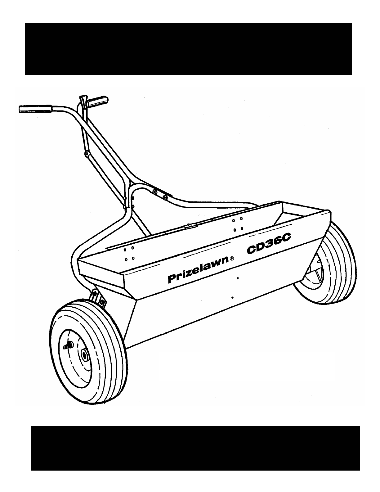
Prizelawn® CD36C
COMMERCIAL DROP SPREADER
MODEL CD36C
OWNER’S MANUAL
Page 2
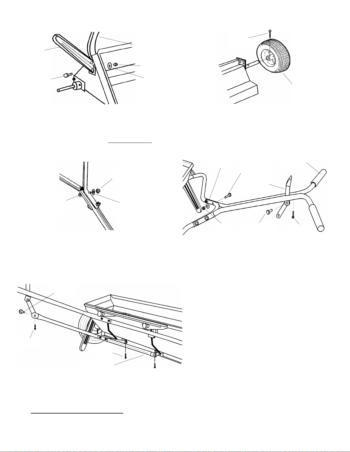
Leg
Assembly Instructions
3/16 X 2”
Handle Brace
Nut
Cotter Pin
1/4-20 X 1/2”
Hex Bolt
Lock
Washer
1. Remove spreader and components from carton.
Place Hopper on it’s front panel, insert two (2) 1/4-20
X 1/2” Hex Head Bolts through the Leg, flattened
end of Handle Brace, and holes in Hopper as shown.
Install Lockwashers and Nuts but do not tighten
Repeat on opposite side.
Nut
1/4-20 X 1 1/2”
Hex Bolt
Lock
Washer
3. Install Control Tube between the
Control Tube Braces and secure with (2)
1/4-20 X 1 1/2” Hex Bolts, Lockwashers,
and nuts.
1/4” D.
Clevis
Drive Wheel
2. Slide Wheels onto each end of Axle with
the longer portion of the Wheel facing the
Hopper. Secure Wheels with 3/16 dia. x 2”
Cotter Pins.
.
Lock
Washer
1/4-20 X 1 1/2”
Hex Bolt
Handle Lever
Assembly
Handle Grip
Nut
1/4” D. Clevis
Cotter
4. Stand spreader upright on Wheels. Attach
Upper Handle assembly to Handle Brace
(make sure Handle is positioned as shown)
using (4) 1/4-20 X 1 1/2” Hex Bolts, (4) Lock
Washers, and (4) Nuts. Tighten securely.
Install Handle Grips onto Upper Handle.
Slide Handle Lever assembly between
Handle Brackets and secure with 1/4 dia,
Clevis and Cotter Pin. Make sure Lever
pivots freely.
Cotter
Cotter
Control Tube
Brace
5. Slide the ends of the Control Tube Braces over the Studs on
the Shutoff Bar Brackets, secure with Cotter Pins. Attached
opposite end of Control Tube to the Handle Lever using 1/4 dia.
Clevis and Cotter Pin. Make sure Handle Lever operates freely.
Tighten all Nuts left loose in step #1.
I
6. To check spreader for completed shutoff,
pull the Handle Lever back to the “O FF ”
position. Turn spreader over to see if the
Shutoff Bar completely covers the holes in
the bottom of the Hopper. If not, stand the
spreader upright on Wheels push the Handle
Lever forward to the “ON” position. Loosen
the Bolts in the Hopper holding the Handle
Brace. Push down on the Handle Brace and
the front of the Hopper. Retighten Bolts and
check the shutoff.
Page 3
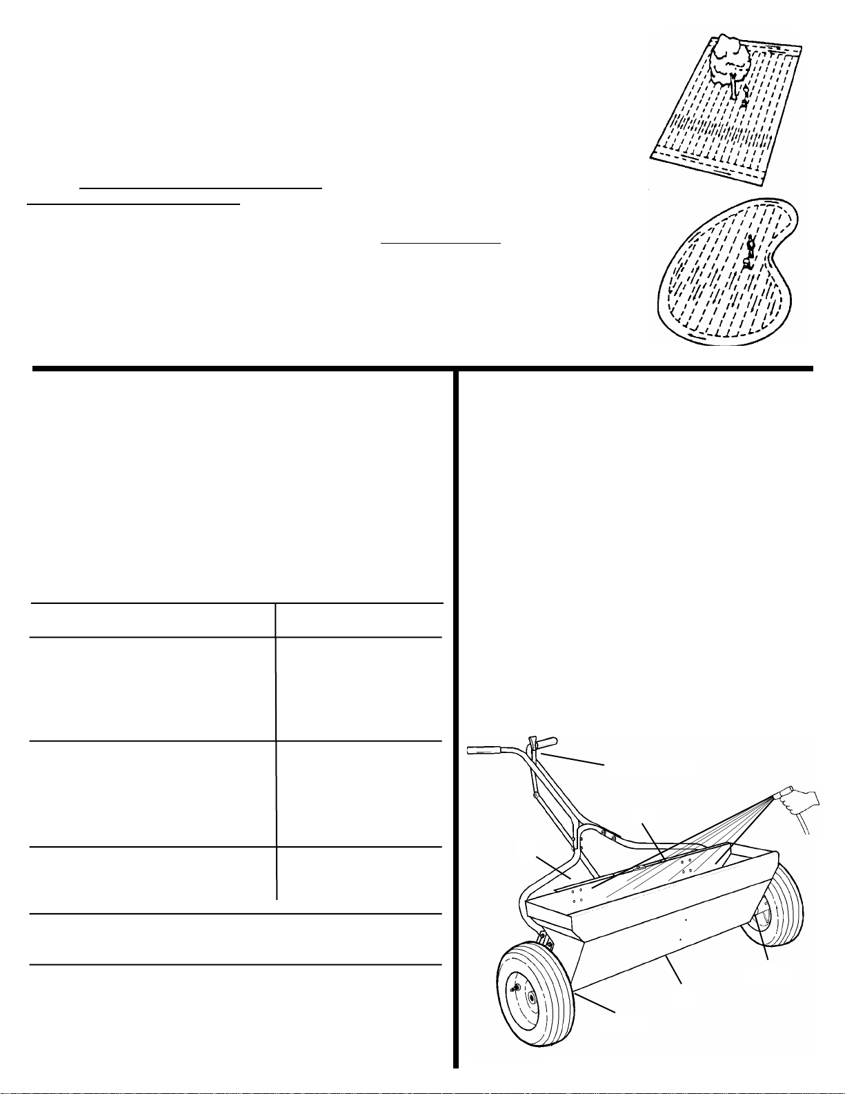
Operation
1. Before filling Hopper, make sure spreader
Handle Lever is in the “OFF” position. Always fill
spreader on walk or drive, not on the lawn.
2. Loosen Rate Control Knobs and move the Tie
Bar to setting recommended for the product
applied. If PrizeLAWN settings are not available,
use Scotts
known, refer to “DETERMINING APPLICATION
RATES” section of this book. Retighten knobs after
setting is made.
® drop spreader settings. If setting is not
3. Always push spreader, do not pull.
Start spreader in motion and as it passes
over the area to be treated, push Handle
Lever to the “ON” position. Close Handle
Handle Lever at the end of each pass.
4. Operate spreader at 3 MPH pace.
(33.3 feet in 7.5 seconds)
5. Apply two header strips at each end
of area to treated and then proceed
lengthwise between the header strips.
Be sure to overlap the wheel tracks
slightly to prevent streaking.
6. When applying lime, do not use lime-
stone that is so finely ground that it will
pack inside the Hopper, or use hard,
abrasive particles which will damage
the spreader.
Use only compacted, free flowing, nonabrasive lime products.
Determining Application
Rates For Drop Spreaders
Maintenance
The following procedure pr ovides a means of accurately
determining drop spreader settings when settings do not
appear on the package, or to “fine tune” the manufacturer’s
recommend settings. Spreader rates can vary due to
walking speed, condition of turf. humidity, physical characteristics
of the product being applied, or condition of the spreader. It is
good practice to double check settings using the following
method:
PROCEDURE EXAMPLE
1. The manufacturer will recommend The contents of this
coverages on the product package. package (25 lbs.)
Generally, it is stated as applying covers 2,000 square
a certain number of pounds of feet.
product per 1,000 square feet.
2. Determine the amount of mate ria l 2,500 divided by 2,000
in pounds to cover 100 square square feet= 1.25 lbs.
feet. Add two zeros to weight
of bag and divide that by the
square foot coverage.
3. To change the decimal portion 0.25 x 16 oz. = 4 oz.
of answer in step #2 to ounces, Total weight = 1 lb.- 4 oz.
multiply decimal portion by 16.
4. On a clean walk of driveway, measure out 33.3 feet- the
distance required to cover 100 square feet.
5. Add a measured amount of product to the spreader- 2 to 3
times the recommended rate. Operate spreader at a brisk walking
speed (3 mph of 33.3 feet in 5. sec.) over the measured distance.
Empty the spreader and weigh the amount left. Compare with the
beginning amount; the difference is the amount applied. Adjust the
setting up or down to achieve the correct application rate.
1. Never store unused material in spreader. Return
unused product to its original container.
2. Set Rate Slide on the highest number, open
spreader and spin Wheels to remove excess material.
3. Wash out Hopper thoroughly after each use to
remove material clinging to surfaces. Pay close
attention to area between the Shutoff Bar and Hopper.
Allow spreader to completely dry.
4. Oil bottom of Hopper, Control Housing Spring and
Agitators at the Center Bearing. Lubricate Axle
Bearings with grease. Store spreader in open position.
“Open”
Oil
Oil
Grease
Oil
Grease
Scotts® is a registered trademark of The Scotts Company
Page 4

Parts List for Model CD36C
14
24
11
10
13
9
12
7
15
6
8
16
24
4
19
17
18
22
3LH
3RH
20
21
1
2
5
23
ITEM PART # DESCRIPTION
1 14211-1 HOPPER ASSEMBLY
2 14414-2 SHUTOFF BAR ASSEMBLY*
3 RH. 14643-1 AGITATOR/AXLE ASSEMBLY-LH. *
3 LH. 14644-1 AGITATOR/ AXLE ASSEMBLY-RH.*
4 14231 BEARING SUPPORT ASSEMBLY*
5 14235 AGITATOR BAFFLE* (2)
6 14227 END HANGER* (2)
7 14007 AXLE GREASE SEAL* (2)
8 14222-1 PLATE ASSEMBLY-BEARING END* (2)
9 90005 GREASE FITTING* (2)
10 14006 AXLE BEARING* (2)
11 15032 WHEEL & TIRE ASSEMBLY (2)
12 12714 LEG (2)
13 12704 RATE CONTROL KNOB* (2)
14 14237 TIE BAR*
15 14286 SPRING HOUSING ASSEMBLY* (2)
16 12708 POINTER*
17 15029-1 HANDLE BRACE
18 15046 UPPER HANDLE ASSEMBLY
19 14047 HANDLE LEVER ASSEMBLY W/ CHAIN
20 14870 HANDLE GRIP (2)
21 14415-1 CONTROL TUBE
22 14409 CONTROL TUBE BRACE (2)
23 15066 FASTENER PACKAGE
24 14236 RATE PLATE* (2)
— 15063 PARTS PACKAGE (NOT SHOWN)
*Parts included in hopper assembly
PART OF OUR SERVICE IS PROVIDING
REPLACEMENT PARTS. Parts may be
obtained through your local distributor.
Be sure to give:
1. SPREADER MODEL NUMBER
2. SPREADER NAME
3. PART NUMBER
4. NAME OF PART AS SHOWN
IF YOUR LOCAL
DISTRIBUTOR CANNOT
SUPPLY PARTS,
CONTACT:
PSB Company
555 West Goodale Street P.O. Box 1089
Columbus, Ohio 43216-1089
614-228-5781 EXT. 2655
© 2003 PSB COMPANY
 Loading...