

Page 1

CSWE 1
Introduction
This product manual is intended for users and
servicers of the CSWE1 Automatic Ice Machine.
Table of Contents
Specifications: . . . . . . . . . . . . . . . . . . . . . . . . . . . . . . . . 2
Installation: . . . . . . . . . . . . . . . . . . . . . . . . . . . . . . . . . 3
Plumbing: . . . . . . . . . . . . . . . . . . . . . . . . . . . . . . . . . . 4
Initial Start Up . . . . . . . . . . . . . . . . . . . . . . . . . . . . . . . . 5
Changing the bin door and lower panels. . . . . . . . . . . . . . . . . . . . . . 6
What to expect: . . . . . . . . . . . . . . . . . . . . . . . . . . . . . . . 7
Maintenance: . . . . . . . . . . . . . . . . . . . . . . . . . . . . . . . . 8
Cleaning the interior components. . . . . . . . . . . . . . . . . . . . . . . . . 9
Condenser . . . . . . . . . . . . . . . . . . . . . . . . . . . . . . . . . 10
Service Diagnosis . . . . . . . . . . . . . . . . . . . . . . . . . . . . . . 11
Service Diagnosis . . . . . . . . . . . . . . . . . . . . . . . . . . . . . . 12
Service Diagnosis . . . . . . . . . . . . . . . . . . . . . . . . . . . . . . 13
Operational Characteristics . . . . . . . . . . . . . . . . . . . . . . . . . . . 14
Keep this manual for future reference.
A parts list is located in the center of this man ual, prin te d on yellow paper.
This manual is printed on recycled paper.
December 1995
Page 1
Page 2
CSWE1
Specifications:
This ice machine requ ires 11 5 v olt s A C. It is
designed only f o r ind oor in sta llat ions, in a
controlled environment.
Limitations: Minimum Maximum
Air Temp erature 55
Wat er T e mp. 40
V o lt age 104 126
Water Press. 20 psi 80 psi
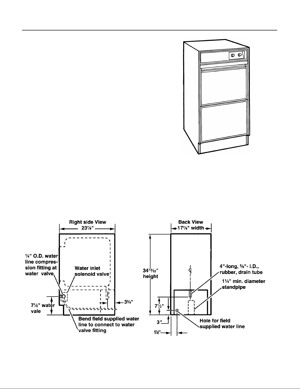
It will fit in a space 18" wide and 34.5 " high and
24" deep. A potable water supply and drain is
required.
Scotsman Ice Systems are designed and
manuf a ct ured wit h th e hig he st regard f or safety
and perf ormance . Th e y me et or exceed th e
standards of UL, NSF and CSA .
Scotsman assu mes no liability or resp onsibilit y of
any kind f or products manufactu red by Scot sma n
that have been altered in any way, including the
use of parts not specific ally appro v ed by
Scotsman. Scotsman reserves the right to make
design changes an d/ or imp rovements at an y time .
Specifications and designs are subject to change
without notice.
o
F. 100oF.
o
F. 100oF.
Refrigeran t charge is 6.7 5 oz. of R -134 a.
December 1995
Page 2
Page 3
Installation:
CSWE1
Proper installat ion is a necessit y, becau se an
improper installat ion will cause operation al
problems that are NOT cove red by any warra nt y. It
is the customer’ s resp on sib ility to contact a
qualified installer.
Proper electrical supp ly, water supply and floo r
drain must be a v ailable. An elec trical ground is
required.
Do NOT clo se in the fron t o f th e ice mak e r. The ice
machine requires space at the fro nt base to
discharge warm air.
If required by sanitation codes, seal the cabinet to
the floor with an appro v e d sealant. Legs are not
available for this machine.
Locatio n:
The ice machin e must be insta lled indo ors , in a
controlled en vironment. Th ere must be room to
open the ice machine door and room to mo v e the
ice machine out for service, if needed.
The unit may be built in at the to p, sides and bac k.
Electrical:
Follow all local, state and national codes. If
needed, obtain the services of a licensed
electrician.
1. A separate 115 v olt, 15 amp circuit is
recommended. A ground is required.
2. Do not use an ext en sio n cord . Have a grounded
outlet insta lled close enoug h to the planne d
installed posit ion of the ice machin e so that th e ice
machine’ s plug can be plugged in directly.
Warm Air Out
December 1995
Page 3
Cool Air In
Page 4
CSWE1
Plumbing:
Connect a 1⁄4" OD copper tube to a threaded
compression fit ting on the inlet w at er v a l v e . There
is an acc e s s ho l e i n the back of th e cabinet fo r
rout ing the tube.
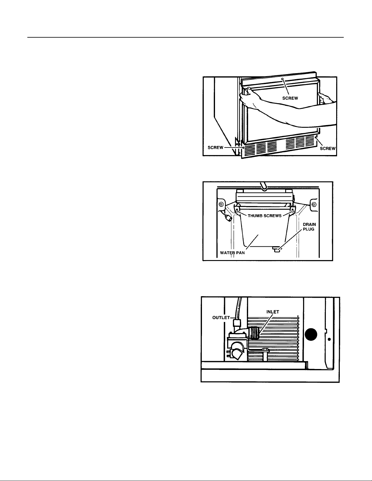
1. Remove the two screws in the lower grille area
and one screw from the center pane l support. Pull
forwa rd and down to remo v e the lowe r acce ss
panel.
2. While th e panel is off , rotate the f an t o check
that it moves freely.
3. Open the ice bin door, and slightly loosen, but
Do Not Remov e the thumb scre ws ho ldin g the
cutter grid and water pan in place.
4. Have a shut off va lv e ins ta lled on the potab le
cold water supply tubing near the ice machine.
5. Connect to the shut off valve sufficient length of
1
⁄4" OD copper tubing to connect to the ice
machine.
1
6. Route the
the back of the cabin et . If the machine is to be built
in, route the tubing so that it will extend past the
front of the cabinet when the cabinet is pushed
into its insta lled pos itio n.
⁄4" copper tubing through the hole in
7. Flush the wat er line int o a buc k et to discharge
any dirt that may be in the line.
8. Loc at e the drain tube at the bac k of th e c abine t.
Determine the required locat ion of the dra in tu be
when the cabin et is in its cor rect posit ion, and
install a 1
below where the drain tube outlet will be. Add
insulatio n to the outside of the drain tube if d esire d.
Follo w all local code s regardin g requireme nt s f or
air gaps.
9. Plug the i ce machine into a grounde d outlet.
10. Slid e the ice mac hin e back and observe that
the water inlet tube mo v es f orw ard thru the ice
machine.
11. An adapter fitting is furnished in the ice
machine’s parts bag. Place it on the inlet water
valve and connect the 1/4" OD tube to it. Be sure it
is water tight .
12. Check the level of the ice machin e fro nt to bac k
and left to right. Shim as needed.
1
⁄4" minimum diameter standpip e directly
December 1995
Page 4
Page 5
Initial Start U p
Note: If the ice mach ine is inst alled above 2, 00 0 ft.
the bin and e vaporato r th e rmo stats well need to be
adjusted. Remove the thermostats and adjust
them as shown on the labels of the thermo sta ts.
Return the thermostats to their original positions
after adjustment.
1. Open the hand water shut off valve and check
for lea ks at the inle t w at er valve. Tigh te n tub ing as
needed.
2. Replace the lower access panel.
3. Switch on the elect rical pow er.
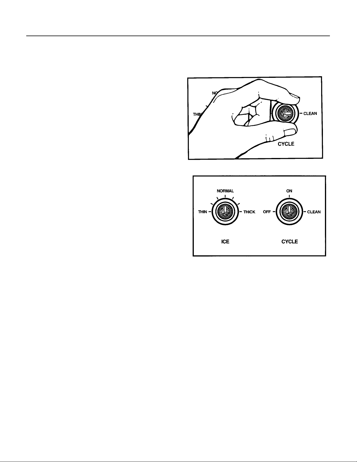
4. Switch the ic e machine on by rot at ing the cont rol
knob to the CLEAN po sitio n. The water pump
should be oper ating.
5. Rotate the co nt rol kno b to th e ON pos itio n. The
fan in the cabinet should be blowing air in and out
of the front grill.
The ice machine will begin to mak e ice , bu t do not
expect much production for the first 3 hours.
CSWE 1
Do not adjust ice th ickness until the machine has
run for 24 ho urs.
6. Aft er 24 hours of run time, chec k the ice
thickness. If needed, adjust thickness by rotati ng
the ice thickne s s knob. The best thicknes s of ice i s
1
⁄2".
December 1995
Page 5
Page 6

CSWE1
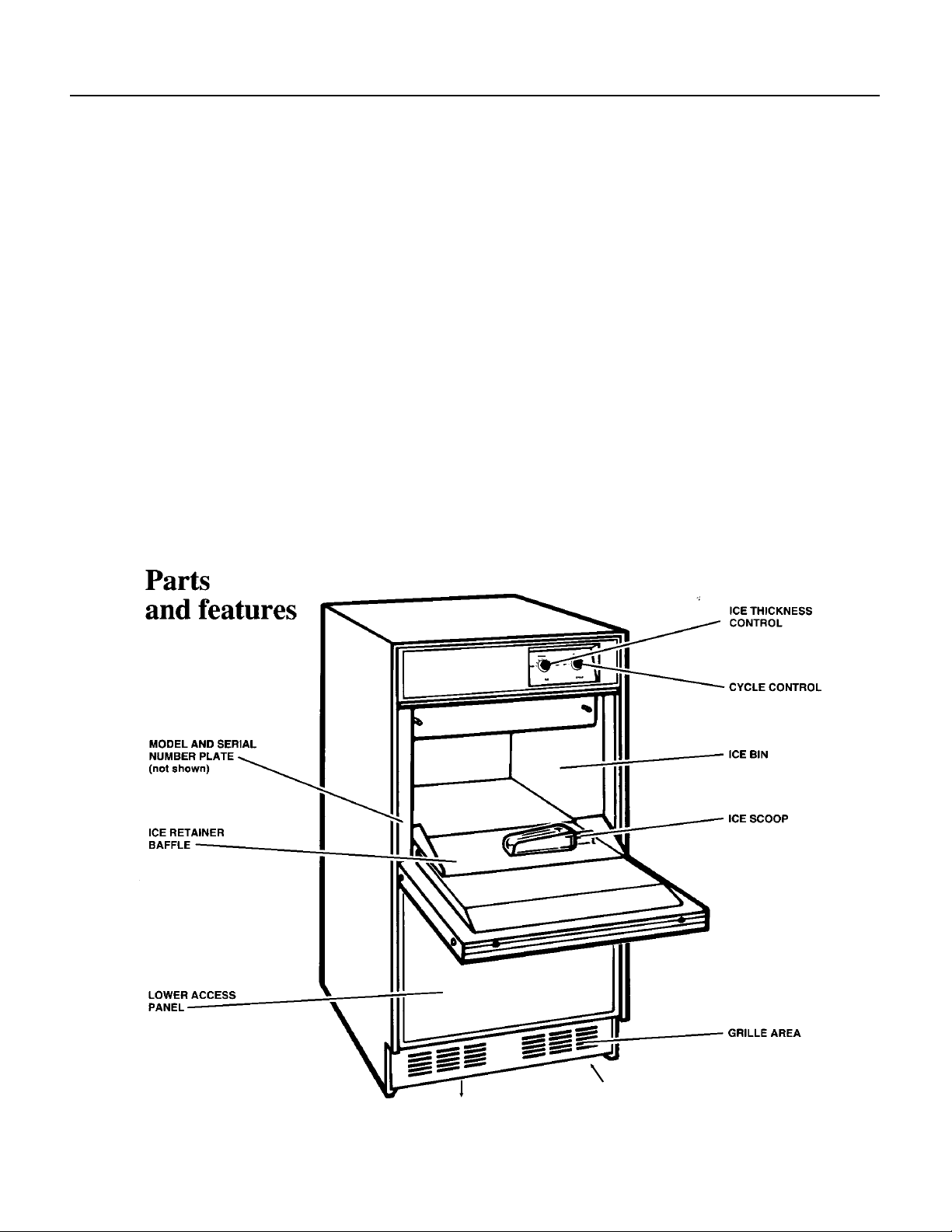
Changing the bin door and lower panels.
The bin doo r and lo wer panels can be custo mi z ed
to match wood cabinets. The size of the door panel
1
is: 11
panel is: 11
1. Cut pane ls, makin g sure that th e wood grain
matches the dire ctio n of the cab ine t woo d grain . It
is a go od idea to co ver the edges of a wood p an e l
with moisture resistant sealant.
2. Open the bin door and remove the two screws
holding the handle to the top of the door, remove
the ha ndle.
⁄4" high x 17" wide. The size of the low er
15
⁄16" high x 17" wide.
Lower Panel:
1. Rem ove the thr ee screws that ho ld the lower
panel assembly an d the two scre ws at the top of
the lower panel. Remove the top of the lower panel
assembly.
3. Slide the meta l panel ou t of the door.
4. Break off the ribs on the door insu lat ion .
5. Slide the wood panel into the bin door frame .
6. Reat ta ch th e handle with the two scre ws.
2. Slide the metal pan el and the space r pane ls out
of the lower panel assembly.
3. Slide the metal panel back into the lower panel
assemb ly, slide the wood panel in fro nt of the
met a l panel.
4. Reattach th e top of the panel with the two
screws and replace the three screws that hold th e
lower panel assembly.
December 1995
Page 6
Page 7

What to expect:
CSWE 1
When the machin e is on, and makin g ice the
compressor , f a n moto r and wat er pump will b e on.
Pe riodica ll y, the water pump and fan will stop and
ice will be "harvested".
Wat er flo ws o v er an inclined freezing surface, and
gradually free zes into a slab. The ice siz e
thermostat measures the temperat ure of the
freezing su rface and the setting of that the rmost at
determines the thickness of the slab.
The ice machin e must ha ve good vent ilat ion in
order to work properly. Do NOT block the air flow
in front of the mach ine .
During the ice release cycle, the ice slab slide s
down onto a hot wire cutter grid and, aft er the grid
melts thru the ice, the individua l cubes f a ll into the
ice storage bin portion of the machine.
The ice machin e will contin ue to prod uc e ice until
the bin is full. Then the ice machine will shut do wn
until the lev el of ice in the bin f alls below the bin
thermostat well.
The ice storage bin is not refrigerated, so there will
be some melting. This will vary with the
temperat ure of the room whe re th e ice mac hin e is
located.
December 1995
Page 7
Page 8

CSWE1
Maintenance:
The water syste m, inclu ding the filt er scree n in the
inlet water valve, needs to be cleaned period ica l ly.
Instructions are located on the inner door panel.
Water System Cleaning:
1. Place the cycle cont rol knob in th e Off position.
2. Remove the two thumb screws, and slide the ice
cutter grid f orw ard, out of the tw o slot s near the
water pan.
3. Unplug the electrical harness.
4. Remove all ice from the storage bin and the
freezing pla ce .
5. Dra in t he w ater pa n by re mo ving th e drain plug.
When finish ed , repla ce the drain plug.
Prepare the clea nin g solu tio n b y thoroughly mixing
2 ounces of Scotsma n Ic e Mach ine Clean er int o 2
quarts of hot (95
solution is 6 ounc es of powde red citric acid and 2
quarts of hot water.
7. Pour cleaning solution into water pan and turn
the switch to "Clean". If solution foams while
pouring, stop until fo amin g su bsid es , then add
balance of solution. Allow solut ion to circulate until
scale has disso lv ed . The circulating so lut ion ma y
not cont act scale on th e side fla ng es of the
freezing plate. To remov e this scale, wear rubber
glov es an d use a sta inle ss st ee l spon ge or pad
dipped in cleaning solution to scrub the side
flanges until the scale is removed. Generally scale
will be dissolved in 15 to 30 minutes . Se v ere scale
formation may req uire rep ea tin g the clea nin g
process with a fresh qu an tit y of solut ion if the scale
has not dissolve d afte r 30 minu tes.
8. Turn swit ch to "Of f" a nd dra in.
o
F - 115oF.) water. An alternative
Scotsman ice machine cleaner
contains acids. Acids may
cause burns.
If swallowed do not induce
vomiting. Give large amounts of
water or milk. Call Physician
immedi a t ely. In case of external
contact, flush with water.
K eep out of the reach of children .
6. Pour 2 quarts of hot water into the water pan
and turn the cycle control t o "clea n". This step
warms up the system and allows the cleaning
solution to be more ef fective. All the circulate 5
minutes. Turn switch to ’Off" and dra in.
9. Follow cleaning with two fresh w ater rinses,
circulating each rinse f or 5 minute s , and dra in.
10. This completes the "in pla ce" cle an ing an d
sanitizing of the wa te r s yst em a nd free zing plate.
Other interior compon ents mu st also be cleaned
and sa ni tized.
December 1995
Page 8
Page 9
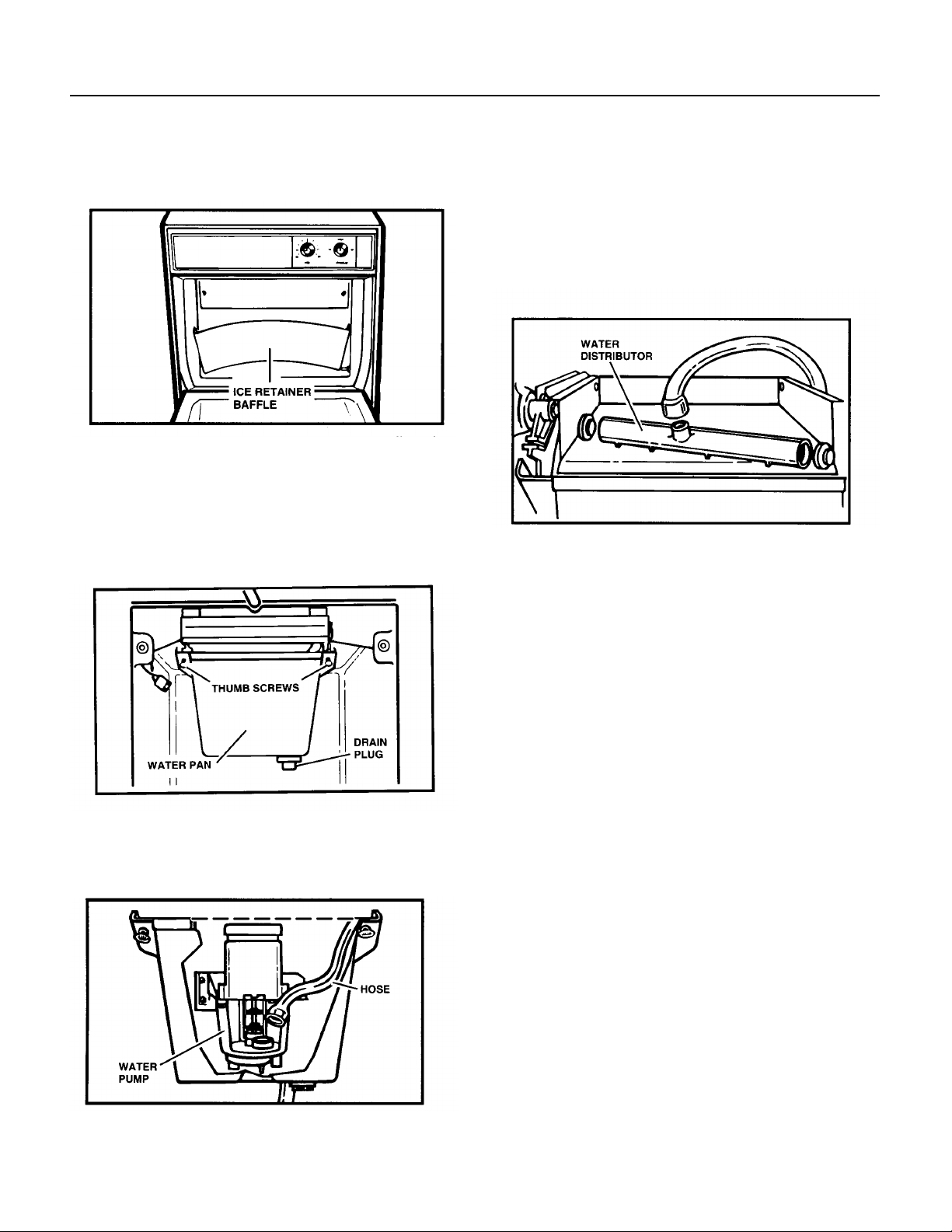
Cleaning the interior component s.
CSWE 1
1. Turn th e c ycle contro l knob to "Off" an d
disconnect the elect rical po wer sup ply to the ice
machine. Open the storage bin door and remove
any ice that is in the bin.
2. Remove the ice retainer baffle b y flexing it and
sliding it off the studs.
3. Remove the ice cutter grid by unscre wing the
two thumb scre ws, sliding the grid forward, and
unplugging the electrical wire harness.
6. Remove the water distributor from the freezing
plate. It is held in pla ce b y rubber end ca ps.
Remov e the inlet hose an d clean all water
distributor hole s and the small orifice in the inle t
side of the dist ributor . When replacing the
distributo r, make sure the end caps are located in
the evaporator flange detents and that the water
distributor holes face down.
7. Wash the interior components (ic e retain er
baffle, cutter grid, water pan, inlet hose and water
distributor) and the ice storage bin, door gasket
and ice scoop with mild soap or detergent and
warm water. The components s hould also be
cleaned in a solution of 1/4 oz. of chlorine bleach
mixed with 1 gallon of warm wa te r.
4. Remove the water pan by unscre wing the two
thumb screws.
5. Remove the hose from the water pump.
Do NOT w as h pla st ic pa rts in the dishwasher. They
cannot withstand temperatures above 145
o
C.)
(63
8. Replace the interior components (water
distributor, inlet hose, water pan, cu tt er grid, and
ice retainer baffle).
9. Chec k th e f ollowing:
o
F.
••Hose from water valv e is in the water pan.
••Rubber drain plug is in the water pan.
•• Water distributor is seated and holes are fac ing
down.
••Hose is re con nected to th e pump and the w ater
distributor.
••Hose from the water pan is insert ed into the
storage bin drain opening.
10. Reconnect th e ele ctric al ha rness, and slide
cutt er g rid i nto place. Tighten the thumb screws.
December 1995
Page 9
Page 10

CSWE1
Condenser
The air cooled condenser will also need to be
cleaned periodically.
1. Turn the cont rol knob to OFF.
2. Remo ve the two screws in the lower grill area
and the one screw from the center of the front
panel support.
4. Remove dirt and lint from the condenser fins
and the unit compartment with a brush attachment
connected to a vacuum cleaner.
5. Return the lower access panel to its original
position and attach with the original screws.
3. Pull f o rwa rd and down to remo v e the lo we r
access panel.
6. Turn the Con t rol Knob to O N .
December 1995
Page 10
Page 11

CSWE1
Service Diagnosis
Problem Probable Cause Possible Solution
Compressor will not run, no ice in
bin
Compressor runs, but no ice in bin Water supply off Restore wat er sup ply
Compressor runs continuously,
bin full of ice
Low ice yield Located in cold area Move to warmer area (abov e
Located in cold area Move to warmer area (abov e
Power disconnected Connect power
Defective compressor start relay Replace relay
Service switch in OFF positio n Move switch to ON
Bin thermostat contacts open Replace bin thermostat
Defective compressor motor Replace compressor
Control knob in Clean position Move to ON
Inlet water valve does not work Check valve, replace if needed
Evaporator th ermos ta t out of
calibration
Hot gas solenoid stuck "open" Repair or r eplace
Inoperative refrigeration system Repair sealed system
Excessive use of cubes Advise custo mer
Cutter grid circuit open Check circuit
Incorrect wiring Check against wiring diagram
Water inlet tu be from valve not
inserted int o water pa n
Bin thermostat out of calibration Re calibrat e or replace
Bin thermostat contacts stuck shut Replace thermostat
Incorrect wiring Check against wiring diagram
Water falling on cubes Check wate r syste m components
Bin thermostat out of calibration Re calibrat e or replace
Evaporat or thermostat set to
produce cubes too thin or too thick
Hot gas solenoid stuck partially
open
Insufficien t ref rig era tio n Check and repair sealed syst em
Not enough water being
circulated over the evaporat or
o
55
F.)
Re calibrate or replace
Insert tube into water pan
o
55
F.)
and see that they are in th e
proper place
Adjust to 1/2 " thick
Replace solenoid valve
Check for restriction in water
lines. Check water pump and
motor.
December 1995
Page 11
Page 12
CSWE1
Service Diagnosis
Problem Probable Cause Possible Solution
Excessive wat er dripp ing on ice Water pan overflowing Check overflow tube for
restriction s. Ov erflo w hos e not
inserted in liner drain. Incorrect or
worn flow washer in the inle t
water valve.
Water pan out of position Install correctly
Water inlet tube from wate r valve
not inserte d in wat er pan.
Ice jam on cutter grid ca usin g
water to flow int o bin
Mineral build up on evapora tor High mineral cont ent in wat er Clean the water sys tem
Ice cubes too th in Evaporator thermos ta t set for th in
cube
Non enough water being
circulated over the evaporat or
Evaporator th ermos ta t out of
calibration
Ice cubes too thick Evaporat or thermostat set at or
beyond maximum thickness
Evaporator th ermos ta t out of
calibration
Overcharge of ref rig era nt Recover, ev acuate, recha rge with
Condenser fan does not run Fan blade stuck against
something
Motor winding s ope n or bearing s
seized.
Open circuit in wiring Check wiring
Defective evaporator thermostat Replace t hermostat
Locate tube properly.
Check cutt er grid, che ck for
mineral build up.
Adjust thickness
Check for restriction in water lines
Check wate r pump and dis tributor
tube
Re calibrate or replace
Adjust thickness
Re calibrate or replace
the nameplate charge of R-134a.
Check fa n blade
Replace fa n mot or
December 1995
Page 12
Page 13

CSWE 1
Service Diagnosis
Problem Probable Cause Possible Solution
Water pump will not run Pump bin din g in hous ing Loca te and remove cause of
binding
Open circuit in pump motor Replace pump
Open circuit to pump Check wiring
Defective evaporator thermostat Replace t hermostat
Water tank empty On initial start up, water will not
be in the tank until the evaporator
thermosta t st ops the free ze cyc le.
Open circuit to water solenoid Locate and repair wiring
Complete wat er line restrict ion Ch eck for close d shut off valve
Defective evaporator thermosta t Replace
Water valve stu ck clo sed Replace valve
Open coil on inlet water valve Replace valve
Water inlet tube from wate r valve
not directing wat er to tan k
Water inlet scree n or filter plugged Clean screen, replace filte r
White ice cubes Water too hard (in excess of 400
ppm)
Insufficien t wat er sup ply in tan k Check for why not en ough wate r
Taste in ice Foods stored in bin Do not put foods in the bin
Packagin g material not all
removed
Too much noise Check tubin g rat tle from conta ct
with tubes, cabinet, etc.
Normal
Position outlet end of t ube into
water pan
Water needs trea tment
Machine harves ts ice too fast -
less than one minute
Remove all packaging
Reposition tubin g
December 1995
Page 13
Page 14

CSWE1
Operational Characteris ti cs
Wat er Solen oid V a lve
.25 GPM flow rate
Evaporator
Stainless steel
Refrigerant Charge
6.75 oz. of R-134a
Running amps
3.5
Cutter grid
8.5 v ol ts
1.9 amps
Evaporato r th ermos tat
Cut in: 38oF.
o
Cut out: 10 to -4
F.
Bin thermost at
Cut in: 41oF.
o
Cut out: 35
F.
System Pressures
Temperature Suction Pressure at the
end of the freeze cycle
(PSIG)
o
Air 70
Air 90
Air 100
Air 70
Air 90
Air 100
F., water 60oF. 1 - 4 65 - 80 18 - 22
o
F., water 60oF. 2 - 5 85 - 100 21 - 27
o
F., water 60oF. 2 - 8 85 - 105 28 - 35
o
F., water 80oF. 1 - 4 65 - 80 20 - 25
o
F., water 80oF. 2 - 5 85 - 100 23 - 30
o
F., water 80oF. 2 - 6 85 - 105 30 - 38
Discharge pressure at
the en d of the freeze
cycle (PSIG)
Cycle time in minutes
December 1995
Page 14
Page 15

Index
A
Adjustment . . . . . . . . . . . . . . . Page 5, Page 11, Page12
C
Cleaning . . . . . . . . . . . . . . . . Page 8 - Page10, Page 13
D
Door Panels . . . . . . . . . . . . . . . Page 6
I
Installation . . . . . . . . . . . . . . . Page 3 - Page4
L
Limitations . . . . . . . . . . . . . . . Page 2
R
Refrigerant . . . . . . . . . . . . . . . Page 2, Page 14
CSWE1
December 1995
Page 15
 Loading...