

Page 1

Introduction
CSW45
This manual includes:
Installation Information
•
Use And Care
•
Service Diagnosis
•
and Repair Information
•
Table of Contents
Introduction ,,,,,,,,,,,,,,,,,,,,,,,,,,,,,,,,,,,,,,,,,,,,Page 1
Specifications ,,,,,,,,,,,,,,,,,,,,,,,,,,,,,,,,,,,,,,,,,,,Page 2
Installing The Ice Maker ,,,,,,,,,,,,,,,,,,,,,,,,,,,,,,,,,,,,,,Page 3
Electrical & Leveling ,,,,,,,,,,,,,,,,,,,,,,,,,,,,,,,,,,,,,,,,Page 4
To Adjust The Rear Wheel Height,,,,,,,,,,,,,,,,,,,,,,,,,,,,,,,,,Page 5
Connecting the Ice Maker to a Water Source ,,,,,,,,,,,,,,,,,,,,,,,,,,,Page 6
Water Connection - continued ,,,,,,,,,,,,,,,,,,,,,,,,,,,,,,,,,,,Page 7
Connecting The Drain ,,,,,,,,,,,,,,,,,,,,,,,,,,,,,,,,,,,,,,,Page 8
A Service Parts Section is also included in the center
of the manual.
Drain Pump Kit ,,,,,,,,,,,,,,,,,,,,,,,,,,,,,,,,,,,,,,,,,,Page 9
Reversing the Door Swing,,,,,,,,,,,,,,,,,,,,,,,,,,,,,,,,,,,,,Page 10
Using The Ice Maker ,,,,,,,,,,,,,,,,,,,,,,,,,,,,,,,,,,,,,,,Page 11
Caring For Your Ice Maker ,,,,,,,,,,,,,,,,,,,,,,,,,,,,,,,,,,,,Page 12
Cleaning the Condenser,,,,,,,,,,,,,,,,,,,,,,,,,,,,,,,,,,,,,,Page 13
Cleaning the Interior Components,,,,,,,,,,,,,,,,,,,,,,,,,,,,,,,,,Page 14
Cleaning Interior - continued ,,,,,,,,,,,,,,,,,,,,,,,,,,,,,,,,,,,Page 15
Vacation and Moving Care ,,,,,,,,,,,,,,,,,,,,,,,,,,,,,,,,,,,,Page 16
Before Calling for Service ,,,,,,,,,,,,,,,,,,,,,,,,,,,,,,,,,,,,,Page 17
Technical Service Diagnosis ,,,,,,,,,,,,,,,,,,,,,,,,,,,,,,,,,,,Page 18
Technical Service Diagnosis ,,,,,,,,,,,,,,,,,,,,,,,,,,,,,,,,,,,Page 19
Technical Information ,,,,,,,,,,,,,,,,,,,,,,,,,,,,,,,,,,,,,,,Page 20
Electrical Sequence ,,,,,,,,,,,,,,,,,,,,,,,,,,,,,,,,,,,,,,,,Page 21
Repair Information ,,,,,,,,,,,,,,,,,,,,,,,,,,,,,,,,,,,,,,,,,Page 22
Repair Information ,,,,,,,,,,,,,,,,,,,,,,,,,,,,,,,,,,,,,,,,,Page 23
Repair Information ,,,,,,,,,,,,,,,,,,,,,,,,,,,,,,,,,,,,,,,,,Page 24
July 1999
Page 1
Page 2
CSW45
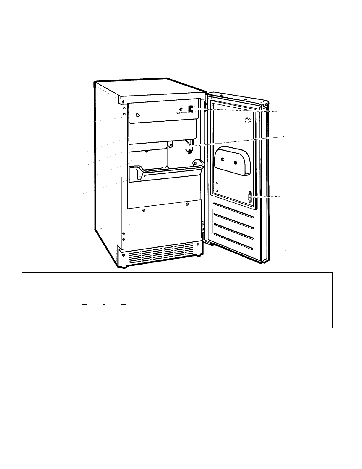
Specifications
Light Switch
Cutter Grid Cover
Water Pan
Model Serial
Number Label
Ice Retainer Baffle
Control Panel
Ice Level Sensor
Magnetic Door
Catch
Lower Access Panel
Model Cabinet Size, w” x d” x h”
14
CSW45A-1B
CSW45PA-1B same same Drain Pump same same
All units are white enamel.
Optional Kits: Trim Kit: KCSWTRIM, Filler Kit for 18” spaces: KCSWFILL, Drain Pump: A37649-001
Scotsman Ice Systems are designed and manufactured with the highest regard for safety and performance.
They meet or exceed the standards of UL, NSF, and CSA.
Scotsman assumes no liability or responsibility of any kind for products manufactured by Scotsman that
have been altered in any way, including the use of any part and/or other components not specifically
approved by Scotsman.
x21 x33
Basic
Electrical
115/60/1 Gravity
Drain Type Power
Cord Supplied, uses
15 amp circuit
Refrigerant
Charge
6.5 oz
R-134a
Scotsman reserves the right to make design changes and/or improvements at any time. Specifications and
design are subject to change without notice.
July 2001
Page 2
Page 3
Installing The Ice Maker
Unpacking
Excessive Weight Hazard
Installation of the ice maker requires a cold
•
water supply inlet of
1
“ (6mm) OD soft copper
4
tubing with a shut-off valve and either a
gravity-drain system or condensate pump to
carry the water to an existing drain.
CSW45
Use two or more people to move and install ice
maker.
Failure to do so can result in back or other injury.
Removing packaging materials
IMPORTANT: Do not remove any permanent
instruction labels inside your ice maker or the Tech
Sheet that is fastened behind the lower access
panel.
• Remove tape and any labels from your ice
maker before using (except the model and serial
number label).
To remove any remaining tape or glue, rub the area
briskly with your thumb. Tape or glue residue can
also be easily removed by rubbing a small amount of
liquid dish soap over the adhesive with your fingers.
Wipe with warm water and dry.
•
Do not use sharp instruments, rubbing alcohol,
flammable fluids, or abrasive cleaners to remove
tape or glue. These products can damage the
surface of your ice maker. For more information,
see the “Important Safety Instructions” section.
Choose a well ventilated area with
•
temperatures above 55°F (13°C) and below
100°F (38°C). Best results are obtained
between 70°F (21°C) and 90°F (32°C). This unit
MUST be installed in an area protected from the
elements, such as wind, rain, water spray, or
drip.
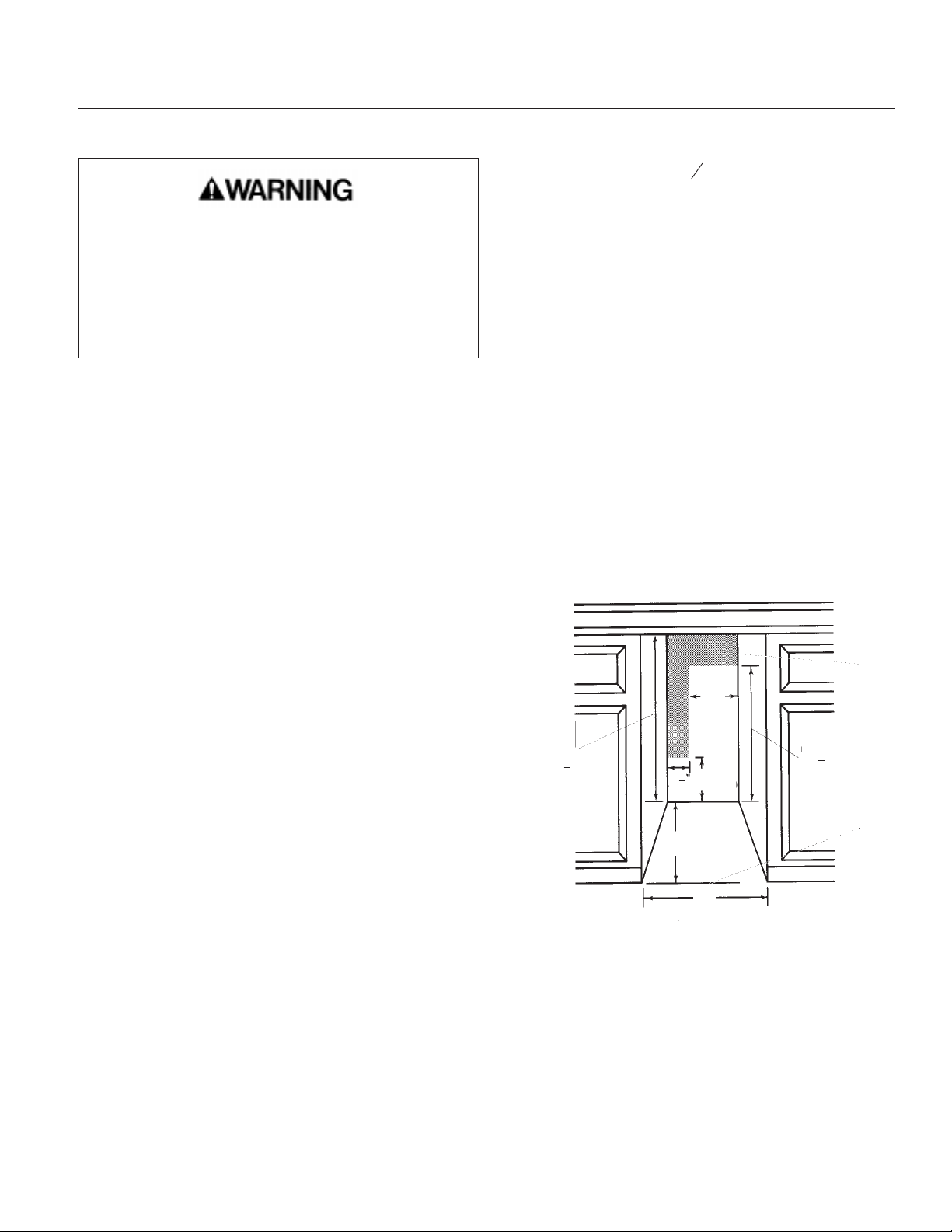
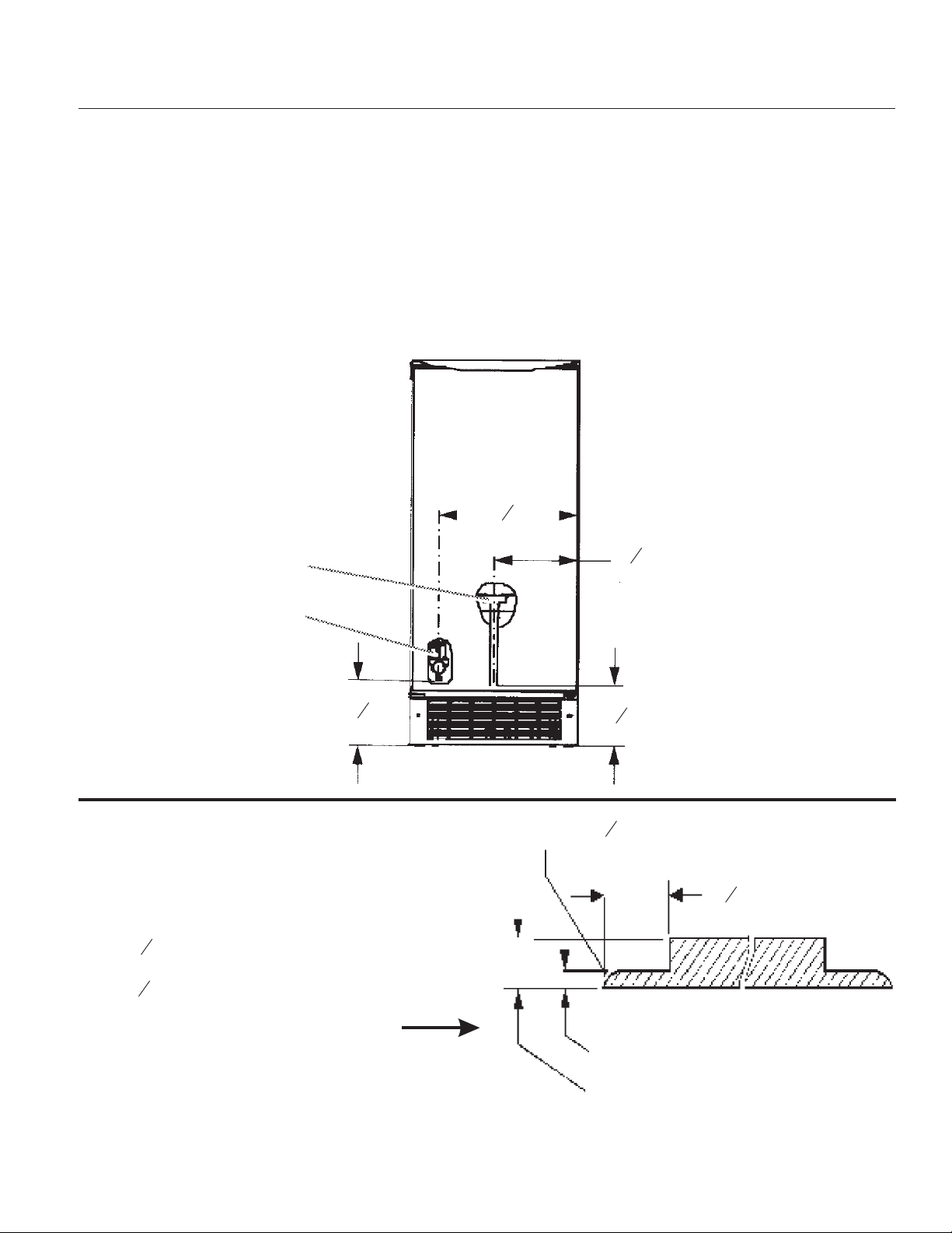
When installing the ice maker under a counter,
•
follow the recommended opening dimensions
shown. Do not place electrical or plumbing
fixtures in the clear zone as indicated by the
gray shaded area.
NOTE: Do not kink or pinch the power supply cord
between the ice maker and cabinet.
1
11
”
2
34”
min
34
max
1
”
2
1
3
9”
2
28
1
”
2
Cleaning before use
After you remove all of the packaging materials,
clean the inside of your ice maker before using it.
See the cleaning instructions in the “Caring for Your
Ice Maker” section.
Space Requirements
•
To ensure proper ventilation for your ice maker,
the front side must be completely unobstructed.
The unit may be closed-in on the top and three
sides, but the installation should allow the ice
maker to be pulled forward for servicing if
necessary.
July 1999
Page 3
24”
15”
1. Clear Zone
2. Floor Level
n You should choose a location where the floor is
even. It is important for the ice maker to be level in
order to work properly. If needed, you can adjust the
height of the ice maker by changing the position of
the rear wheels. See the “Leveling the Ice Maker”
section.
Page 4
CSW45
Electrical & Leveling
Electrical Shock Hazard
Plug into a grounded 3
prong outlet.
Failure to follow these
instructions can result in
death, fire, or electrical
shock.
Do not use an extension
cord.
Do not use an adapter.
Do not remove ground
prong.
Before you move your ice maker into its final
location, it is important to make sure you have the
proper electrical connection:
A 115 Volt, 60 Hz., AC only 15 ampere electrical
supply, properly grounded in accordance with the
National Electrical Code and local codes and
ordinances, is required.
It is recommended that a separate circuit, serving
only your ice maker, be provided. Use a receptacle
which cannot be turned off by a switch or pull chain.
Recommended Grounding Method
For your personal safety, this appliance must be
grounded. This appliance is equipped with a power
supply cord having a 3 prong grounding plug. To
minimize possible shock hazard, the cord must be
plugged into a mating, 3 prong, grounding-type wall
receptacle, grounded in accordance with the
National Electrical Code and local codes and
ordinances. If a mating wall receptacle is not
available, it is the personal responsibility of the
customer to have a properly grounded, 3 prong wall
receptacle installed by a qualified electrician.
Leveling the Ice Maker
It is important for the ice maker to be level in order to
work properly. Depending upon where you install the
ice maker, you may need to make several
adjustments to level it.
Tools required
Carpenter’s level
•
Adjustable wrench
•
1
" socket wrench
•
4
Undercounter Installation
If you are installing the ice maker under a
countertop, then you may need to adjust the height
of the ice maker. The adjustable rear wheels are
preset to position 1 for a cabinet opening height of
34" (86.4 cm).
1
2
3
4
1. For cutout height of 34" (86.4 cm)
2. For cutout height of 34
3. For cutout height of 34
4. For cutout height of 34
1
" (86.7 cm)
8
5
" (87.2 cm)
16
1
" (87.6 cm)
2
July 1999
Page 4
Page 5
To Adjust The Rear Wheel Height
CSW45
Electrical Shock Hazard
Failure to follow these
instructions can result in
death, fire, or electrical
shock.
Disconnect power before
servicing.
Replace all panels before
operating.
1. Using a
1
“ socket wrench, remove the seven
4
screws from the rear access panel and carefully pull
the panel away from the drain hose.
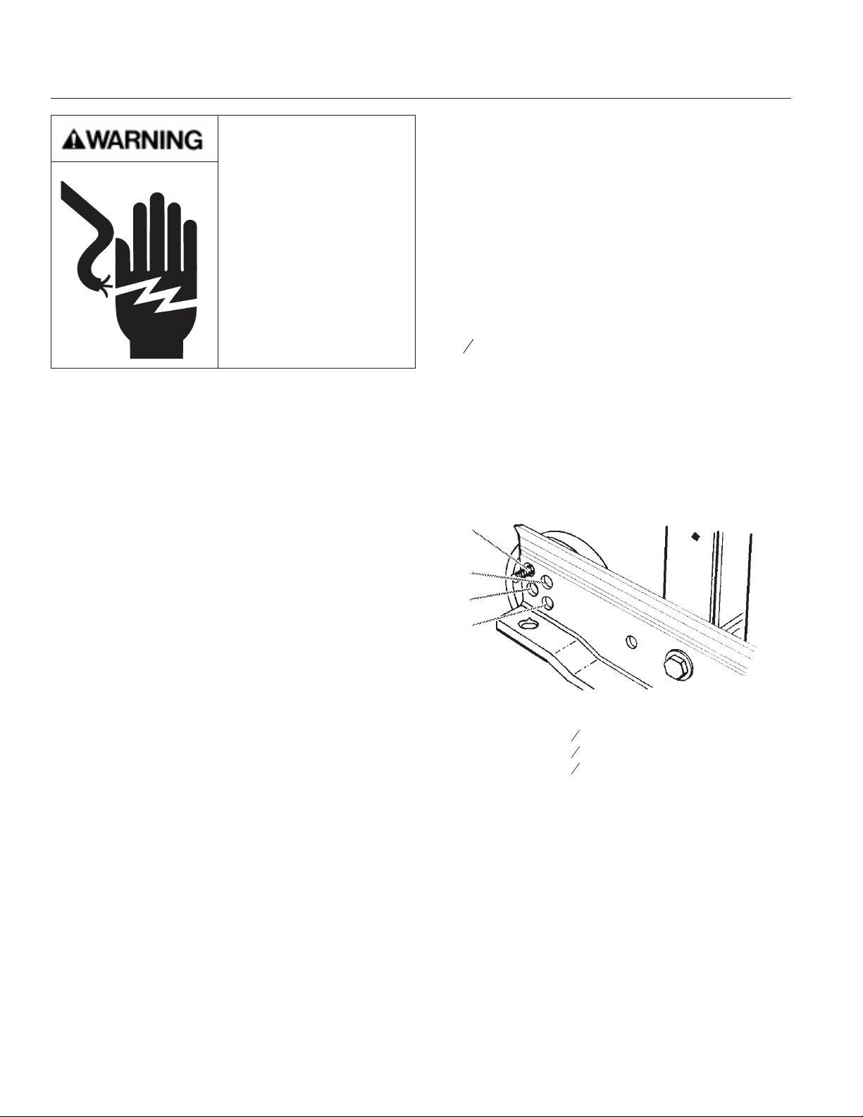
2. Using a
3
“ or adjustable wrench, remove the
8
screw that holds the rear wheel.
NOTE: Pushing up against the top back of the ice
maker takes some of the weight off of the wheels.
This makes it easier to remove the screws.
2. Push up on the top front of the ice maker, and
then locate the leveling screws that are on the
bottom front of the product.
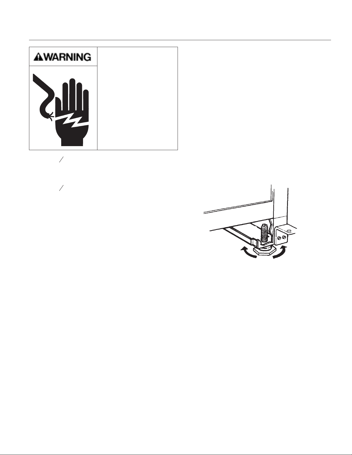
3. Using an adjustable wrench, change the height of
the legs as follows:
Turn the leveling leg to the right to lower that
•
side of the ice maker.
Turn the leveling leg to the left to raise that side
•
of the ice maker.
NOTE: The ice maker should not wobble. Use shims
to add stability when needed.
3. Move the rear wheel and screw to a new position
as needed for your cabinet opening height. Tighten
the screw completely.
4. Repeat Steps 3 and 4 to change the position of
the wheel on the other side.
5. Replace the rear panel and screws. Be sure that
the drain tube is positioned in the opening provided.
6. Use the front leveling legs to make sure the
product is level.
To adjust the front leveling legs
Your ice maker has two adjustable leveling legs to
help you steady the product and make sure it is
level.
SUGGESTION: It is easier to adjust the leveling legs
if you have another person to assist you.
1. Place a carpenter’s level on top of the product to
see if the ice maker is level from front to back and
side to side.
4. Use a carpenter’s level to re-check the ice maker
to see that it is even from front to back and side to
side. If the ice maker is not level, repeat Steps2&3.
If the ice maker is level, go to the “Connecting the
Ice Maker to a Water Source” section.
Freestanding Installation
If you are not installing your ice maker under a
countertop, you will probably not need to adjust the
rear wheel height. Follow the steps outlined in “To
adjust the front leveling legs” earlier in this section.
NOTE: The ice maker should not wobble. Use shims
to add stability when needed.
July 1999
Page 5
Page 6
CSW45
Connecting the Ice Maker to a Water Source
Read all directions carefully before you begin.
IMPORTANT:
All installations must be in accordance with local
•
plumbing codes requirements.
Use copper tubing and check for leaks.
•
Install copper tubing only in areas where
•
temperatures will remain above freezing.
7. Place the free end of the tubing into a container or
sink, and turn on main water supply and flush out
tubing until water is clear. Turn off shut-off valve on
the water pipe.
Slip compression sleeve and compression nut
•
on copper tubing as shown. Insert end of tubing
into outlet end squarely as far as it will go.
Screw compression nut onto outlet end with
adjustable wrench. Do not over tighten.
Before purchasing, make sure a saddle-type valve
complies with your local plumbing codes. Do not
use a piercing-type or 3/16” saddle valve which
reduces water flow and clogs more easily.
Connecting the water line:
1. Unplug ice maker or disconnect power.
2. Turn off main water supply. Turn on nearest
faucet long enough to clear line of water.
3. Find a
1
"to
2
1
" vertical cold water pipe near the
1
4
ice maker.
NOTE: Horizontal pipe will work, but the following
procedure must be followed: Drill on the top side of
the pipe, not the bottom. This will help keep water
away from the drill. This also keeps normal sediment
from collecting in the valve.
4. Using a grounded drill, drill a
1
" (6 mm) hole in the
4
cold water pipe you have selected.
NOTE: Always drain the water line before making
the final connection to the inlet of the water valve to
prevent possible water valve malfunction.
8. Remove the two screws in the lower access panel
and the two screws in the base grille area of the front
panel support. Pull forward to remove the lower
access panel.
9. Position the tubing so it can enter one of the two
access holes located at the right-hand rear of the
cabinet as shown. The tubing should extend beyond
the cabinet front when the cabinet is pushed back
into position. Move the ice machine into position.
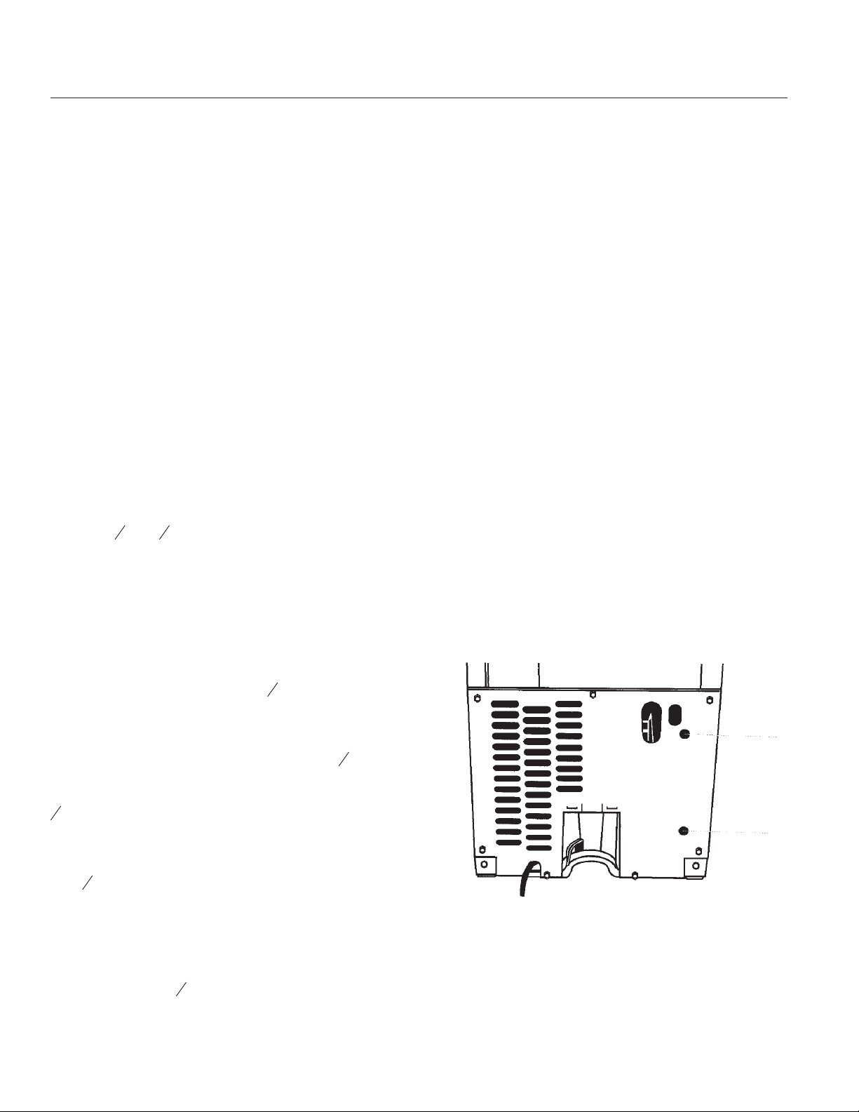
REAR VIEW
1. Upper Water Line Access Hole
2. Lower Water Line Access Hole
5. Fasten shut-off valve to cold water pipe with pipe
clamp. Be sure outlet end is solidly in the
1
-inch
4
drilled hole in the water pipe and that washer is
under the pipe clamp. Do not use a piercing-type or
3
" saddle-type valve which reduces water flow and
16
clogs more easily.
6. Now you are ready to connect the copper tubing.
1
Use
" (6mm) OD soft copper tubing for the cold
4
water supply.
•
Measure from the connection at the front of the
ice maker to the cold water pipe. Add 3 feet to
ensure that you have the proper length. This is
the length of
1
" (6mm) OD soft copper tubing
4
you need for the job. Be sure both ends of the
copper tubing are cut square.
1
2
10. Bend the copper tubing to meet the water valve
inlet on the water valve which is located in the front
of the ice maker cabinet as shown.
July 1999
Page 6
Page 7
Water Connection - continued
CSW45
11. Unscrew the water valve inlet cover, and attach
the copper tubing with the compression sleeve and
nut.
NOTE: To prevent rattling, be sure the copper tubing
does not touch the cabinet’s side wall or other parts
inside the cabinet.
FRONT VIEW
1
12. Turn shut-off valve on. Check for leaks.
Tighten any connections (including connections at
the valve) or nuts that leak. The ice maker is
equipped with a built-in water strainer. If local water
conditions require periodic cleaning or a well is your
source of water supply, a second water strainer
should be installed. Obtain a water strainer from your
nearest appliance dealer and install it at either tube
connection.
13. Replace the lower access panel and screws.
3
12
16
5
7
“
16
2
1. Water Pan Drain
2. Water Valve
11
5
16
Custom Panel (for kit KCSWTRIM):
Customer supplied wood panel must be
•
” thick x
31
•
29
“ high x
64
33
•
14
“ wide
64
and be trimmed as shown in the diagram.
Route Approx
”
3
5
“
8
3
“
8
15
1
“
32
July 1999
Page 7
” Thick Panel
Page 8
CSW45
Connecting The Drain
Gravity drain system
Connect the drain pump hose (provided with the
product) to your drain in accordance with all state
and local codes and ordinances. If the ice maker is
provided with a gravity drain system, follow these
guidelines when installing drain lines: (This will
prevent water from flowing back into the ice maker
storage bin and potentially flowing onto the floor
causing water damage.)
Drain lines must have a minimum of
•
5
" (1.6 cm)
8
inside diameter.
Drain lines must have a 1" (2.5 cm) drop per 48”
•
(122 cm) of run (
1
" per foot [6mm per 30.5cm])
4
and must not have low points where water can
settle.
The floor drains must be large enough to
•
accommodate drainage from all drains.
• The ideal installation has a standpipe with a 1
to 2" PVC drain reducer installed directly below
the outlet of the drain tube as shown. You must
maintain a 1" air gap between the drain pump
hose and the standpipe.
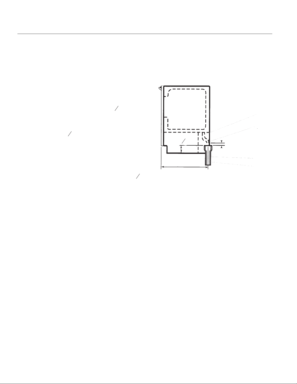
SIDE VIEW
1
"
2
1
2
5
“
4
8
1”
3
23”
4
2”
•
It may be desirable to insulate the drain line
thoroughly up to the drain inlet.
After ensuring that the drain system is adequate,
follow these steps to properly place the ice maker:
1. Plug ice maker into a grounded 3 prong outlet.
2. Re-check the ice maker to be sure that it is level.
See the “Leveling the Ice Maker” section.
3. Push the ice maker into position so that the ice
maker drain tube is positioned over the PVC drain
reducer.
1. Drain Hose
2. 1" Air Gap
3. PVC Drain Reducer
4. Center of drain should be 23” (58.4 cm) from front of door
(with or without the C\v” (1.9 cm) panel on the door).
4. If it is required by your local sanitation code, seal
the cabinet to the floor with an approved caulking
compound after all water and electrical connections
have been made.
5. Plug in ice maker or reconnect power.
Drain pump system (on some models)
Connect the drain pump hose (provided with the
product) to your drain in accordance with all state
and local codes and ordinances.
July 1999
Page 8
Page 9

Drain Pump Kit
1. Remove rear cover.
2. Remove old drain tube.
3. Install new drain tube to bin (use old clamp).
CSW45
Pump, View from
Front of Cabinet
4. Install drain pump into machine. Carefully slide in
aligning the tab on the pump to the rectangular slot
in the unit base.
5. Attach bin drain tube from bin to pump.
6. Connect vent tube to vent connection on pump.
Route vent up through the rear cover. Secure vent
tube to back of ice machine using three clamps and
screws from the kit.
7. Route pump outlet tube to household drain.
8. Power cord from ice machine must be plugged
into pump. Coil up and tape power cord together,
insert between compressor and drain pump. Plug the
power cord into the pump.
9. Line up the two screws at the rear of the pump
and secure the pump using two screws from the kit.
Pump
Mounting Tab
Vent Tube
10. Install rear cover.
11. Connect power cord (pump’s) into the electrical
power supply. This must be a grounded circuit that
conforms to the National Electrical Code and all local
codes and ordinances.
July 1999
Page 9
Discharge
Hose
Pump
Mounting
Screws
Page 10

CSW45
Reversing the Door Swing
TOOLS NEEDED:
5
" wrench,
16
1
" wrench, flat putty
4
knife,
To remove door from hinges:
1. Unplug ice maker or
disconnect power.
2. Remove the handle screws and
handle (on some models). Keep
the parts together and set
them aside.
3. Remove the hinge pin from the
top hinge.
4. Remove the door from the
hinges and screw the top hinge
pin back into the top hinge.
5. Reverse the door endcaps as follows:
• Remove both the screws and endcaps (top and
bottom).
the hinge pin points down. Place the hinge on the top
opposite side of the ice maker and tighten the
screws.
6. Remove the top hinge pin.
To replace door on hinges:
1. Place plastic hinge pin sleeve in the top hinge hole
on the door. Align the door with the top hinge hole
and replace the top hinge pin.
2. Replace the handle and handle screws.
Top Hinge
1. Hinge Pin
2. Hinge Pin Sleeve
3. Hinge
4. Hex Head Hinge
Screw
1
2
3
• Place the top endcap on the bottom of the
opposite side of the door with the long flat side
facing the door front.
•
Place the bottom endcap on the top of the
opposite side of the door with the long flat side
facing the door front.
6. Set the door aside.
To reverse the hinges:
1. Unscrew and remove the top hinge. Replace the
screws in the empty hinge holes.
2. Remove the screws from the bottom of the
opposite side of the ice maker cabinet. Turn the top
hinge upside down so that the hinge pin points up.
Place the hinge on the bottom opposite side of the
ice maker and tighten screws.
3. Remove the plastic hinge pin sleeve from the “old”
bottom hinge and replace it on the new bottom hinge
pin.
4. Remove the “old” bottom hinge screws and hinge.
Replace the screws in the empty hinge holes. the ice
maker cabinet. Turn the hinge upside down so that
4
Bottom Hinge
1. Hex Head Hinge
Screw
2. Hinge Pin Sleeve
3. Hinge
4. Hinge Pin
1
2
3
4
To reverse the door
catch:
1. Remove the hole plugs from the opposite side of
the door and set aside.
2. Remove the screws from the magnetic door catch
and replace it on the opposite side of the door.
3. Push the hole plugs into place on the opposite
side of the door.
July 1999
Page 10
Page 11

Using The Ice Maker
CSW45
Understanding How Your Ice Maker Works
When you first start your ice maker, the water pan
will fill and the system will rinse itself before starting
to make ice. The rinsing process takes about five
minutes.
Under normal operating conditions, the ice maker will
cycle at preset temperatures. The ice level sensor
located in the ice storage bin will monitor the ice
levels.
IMPORTANT
If the water supply to the ice maker is turned off,
•
be sure to set the ice maker control to OFF.
The ice maker is designed to make clear ice
•
from the majority of water sources on a daily
basis. If your results are unsatisfactory, your
water may need to be filtered or treated.
Making Ice
1. Water is constantly circulated over a freezing
plate. As the water freezes into ice, the minerals in
the water are rejected. This produces a clear sheet
of ice with a low mineral content.
3. The water containing the rejected minerals is
drained after each freezing cycle.
4. Fresh water enters the machine for the next ice
making cycle.
5. Cubes fall into the storage bin. When the bin is
full, the ice maker shuts off automatically and
restarts when more ice is needed. The ice bin is not
refrigerated and some melting will occur. The
amount of melting varies with room temperature.
NOTE: As the room and water temperatures vary, so
will the amount of ice produced and stored. This
means that higher operating temperatures result in
reduced ice production.
Setting the Controls
2. When the desired thickness is reached, the ice
sheet is released and slides onto a cutter grid. The
grid divides the sheet into individual cubes.
1. To start the normal ice making cycle, select ON.
2. To stop ice maker operation, select OFF.
NOTE: The CLEAN setting is used whenever
solutions are circulated through the ice maker for
cleaning. Only the water pump and compressor
operate at this setting. See the “Cleaning the Ice
Maker System” section.
July 1999
Page 11
Page 12

CSW45
Caring For Your Ice Maker
Periodically inspect and clean the ice maker to keep
it operating at peak efficiency and to prevent
premature failure of system components.
Both the ice making system and the air cooled
condenser need to be cleaned regularly.
The minerals rejected from the circulating water
during the freezing cycle will eventually form a hard
scaly deposit in the water system which prevents a
rapid release of the ice from the freezing plate.
Clean the ice and water system periodically to
remove mineral scale buildup. Frequency of cleaning
depends on water hardness. With hard water (15 to
20 grains/gal. [4 to 5 grains/liter]), cleaning may be
required as frequently as every 6 months.
Cleaning Exterior Surfaces
Wash the exterior enamel surfaces and gaskets with
warm water and mild soap or detergent. Wipe and
dry. Regular use of a good household appliance
cleaner and wax will help protect the finish.
5. Push the selector switch to CLEAN. (See the
“Setting the Controls” section.) The light will turn on,
indicating that the cleaning cycle is in process. When
the indicator light turns off (approximately 45
minutes), the cleaning cycle is complete. During the
cleaning cycle, the system will both clean and rinse
itself.
6. After the cleaning cycle is complete, remove the
drain cap from the water pan to see if any cleaning
solution is left in the water pan. If cleaning solution
drains from the water pan, you should run the clean
cycle again.
NOTE: Severe scale buildup may require repeated
cleaning with a fresh quantity of cleaning solution.
7. Push the selector switch to ON to resume ice
production.
Do not use abrasive cleaners on enamel surfaces as
they may scratch the finish.
Cleaning the Ice Maker System
1. Push the selector switch to OFF.
2. Wait 5 to 10 minutes for the ice to fall into the
storage bin. Remove all ice from the storage bin.
3. Unscrew the drain cap from the bottom of the
water pan located inside the storage bin as shown.
Allow the water to drain completely.
4. Replace the drain cap. Pour 16 ounces of
Scotsman Clear 1 scale remover into the water pan.
Fill the bottle twice with tap water and pour it into the
water pan.
September 2007
Page 12
Page 13

Cleaning the Condenser
CSW45
A dirty or clogged condenser:
Prevents proper airflow.
•
Reduces ice making capacity.
•
Causes higher than recommended operating
•
temperatures which may lead to component
failure.
Electrical Shock Hazard
Failure to follow these
instructions can result in
death, fire, or electrical
shock.
Disconnect power before
servicing.
Replace all panels before
operating.
1. Unplug ice maker or disconnect power.
2. Remove the two screws in the lower access panel
and the two screws from the base grille area of the
front panel support. Pull forward to remove the lower
access panel.
4. Remove dirt and lint from the condenser fins and
the unit compartment with a brush attachment on a
vacuum cleaner.
5. Replace the lower access panel using the four
screws.
6. Plug in ice maker or reconnect power.
3. Pull the bottom forward and then pull down to
remove the lower access panel.
July 1999
Page 13
Page 14

CSW45
Cleaning the Interior Components
1. Unplug ice maker or disconnect power.
Electrical Shock Hazard
Failure to follow these
instructions can result in
death, fire, or electrical
shock.
Disconnect power before
servicing.
Replace all panels before
operating.
2. Open the storage bin door and remove any ice
that is in the bin.
3. Remove the drain cap from the water pan and
drain thoroughly. Replace the drain cap.
4. Remove the three screws that hold the cutter grid
cover in place.
NOTE: Make sure the plastic spacer from the
right-hand side of the cutter grid bracket stays with
the cutter grid.
1
2
3
1. Cutter Grid Harness
2. Screw
3. Cutter Grid
4. Ice Level Sensor Harness
5. Plastic Spacer
6. Screw
4
5
6
5. Unplug the wiring harness from the left side of the
cutter grid.
1
2
1. Cutter Grid Cover
2. Screws
6. Unplug the ice level sensor from the right side of
the cutter grid. Pull the ice level sensor down and
forward away from the cutter grid.
7. Remove the right-hand screw and loosen the
left-hand screw. Lift the cutter grid up and out and
over the left-hand screw.
July 1999
Page 14
Page 15

Cleaning Interior - continued
CSW45
8. Remove the two screws that hold the water pan in
place. Push down with one hand on the front of the
pan while pulling forward on the bottom back side.
9. Wash the interior components (cutter grid, exterior
of hoses, and water pan) and the storage bin, door
gasket, and ice scoop with mild soap or detergent
and warm water. Rinse in clean water. Then clean
the same parts with a solution of 1 tablespoon (15
mL) of household bleach in 1 gallon (3.8 L) warm
water. Rinse again thoroughly in clean water.
NOTE: Do not remove hoses. Do not wash plastic
parts in dishwasher. They cannot withstand
temperatures above 145°F (63°C).
Changing the Light Bulb
The ice maker has a light bulb in the top of the
storage bin.
To replace it, open the bin door and follow these
instructions:
1. Unplug ice maker or disconnect power.
2. Remove the three screws that hold the cutter grid
cover in place. Reach behind the control panel and
pull the light bulb down from the ceiling.
3. Replace with a 12-volt wedge base-type bulb
(automotive #917). Locate the light bulb receptacle in
the ceiling behind the control panel. Align the flat
edge of the light bulb with the receptacle and snap
the bulb into place.
10. Replace water pan by pushing back on the
bottom with one hand while pushing up and back on
the top. Secure the water pan by replacing both
screws.
11. Check the following:
•
Drain cap from the water pan is in place.
•
Hose from water pan is inserted into storage bin
drain opening.
12. Slide the cutter grid back into place and secure it
by replacing the right-hand screw and plastic spacer.
Then tighten the left-hand screw. Reconnect the
cutter grid and ice level sensor harnesses.
4. Replace the cutter grid cover with three screws.
5. Plug in ice maker or reconnect power.
July 1999
Page 15
Page 16

CSW45
Vacation and Moving Care
To shut down the ice maker:
1. Unplug ice maker or disconnect power.
2. Remove all ice from storage bin.
3. Shut off the water supply.
4. Remove the two screws in the lower access panel
and the two screws from the base grille area of the
front panel support. Pull forward to remove the lower
access panel.
5. Disconnect the inlet and outlet lines to water
valve. Allow these lines to drain and then reconnect
to the valve.
6. Replace lower access panel and screws. Drain
water from water pan by removing the drain cap.
Also, remove water from drain line.
7. Before using again, clean the ice maker and
storage bin.
8. Plug in ice maker or reconnect power.
NOTE: All components of the ice maker are
permanently lubricated at the factory. They should
not require any additional oiling throughout the
normal life of the machine.
WA so can result in death or
electrical shock.
July 1999
Page 16
Page 17

Before Calling for Service
CSW45
Try the solutions suggested here first in order to
avoid the cost of an unnecessary service call.
Unit does not run
n Is the control set to ON?
Be sure that the control is set to ON.
n Is the power cord plugged in?
Firmly plug the cord into a live outlet with proper
voltage.
n Has a household fuse or circuit breaker
tripped?
Replace the fuse or reset the circuit.
n Is the room temperature cooler than normal?
Room temperature must be above 55°F (13°C).
Otherwise, bin thermostat may sense cold room
temperature and shut off even though bin is not full
of ice. Also, unit may not restart once it does shut off.
Unit runs but produces no ice
If there is white scale buildup in the ice maker’s
water or freezing system, you should clean the ice
maker. See the “Cleaning the Ice Maker System”
and the “Cleaning the Interior Components” sections.
Grid is not cutting ice sheets
n Is the cutter grid securely in place?
Unplug the ice maker or disconnect power. Remove
the cutter grid cover and check the cutter grid
harness plug to make sure the connection is secure.
Taste in ice cubes
n Is there unusually high mineral content in the
water supply?
The water may need to be filtered or treated.
n Are there food items stored in the ice bin?
Do not store any foods in the ice bin.
n Were all the packaging materials removed?
Make sure that all packaging materials were
removed at the time of installation. Service Diagnosis
n Is the control set to ON?
Be sure that the control is set to ON.
n Is the water supply connected?
Make sure the water supply is properly connected
and turned on.
Unit runs but produces very little ice
n Is the room temperature hotter than normal?
Room temperatures of more than 90°F (32°C) will
normally reduce ice production.
n Is the condenser dirty?
Dirt or lint may be blocking the airflow through the
condenser. See the “Cleaning the Condenser”
section.
n Is there scale buildup in the ice maker?
July 1999
Page 17
Page 18

CSW45
Technical Service Diagnosis
Symptom Possible Cause Probable Correction
Plug unit it
Unit Off
No power to unit
Unit switched off Check control switch
Ice level control keeping unit off
Transformer Open Check/replace transformer
Control board failed
No water to unit
Pump does not run
Reset circuit breaker or replace
fuse
Room colder than 55
heat
Ice on sensor tube - remove it
Switch unit to Clean, note if all
valves and motors are switched
on for 5 seconds each one after
another. If not, replace the board.
Check/restore water supply
Check water valve
Check connection from control
box to pump
Check/replace pump
o
F., increase
Check for dirty condenser
Unit overheating
Unit runs, makes no ice
Compressor does not run
Low on refrigerant
Hot gas valve leaking thru Check/replace hot gas valve
* If the system has been running in a vacuum AND the leak is found to be on the LOW side, repair the leak
AND replace the compressor.
Check fan blade and motor
Air flow blocked, check for air
obstruction
Check compressor relay
Check compressor windings
Install service ports, weigh out
charge, If low, locate and repair
leak, replace drier evacuate to
300 microns and weigh in
nameplate charge*
July 1999
Page 18
Page 19

Technical Service Diagnosis
Symptom Probable Cause Possible Correction
Dirty air cooled condenser Clean condenser coil
Dirty fan blade Clean fan blade
CSW45
Water valve does not shut off
Low ice making capacity
Unit will not shut off Ice level control failure
Ice size incorrect Evaporator thermistor failure
Ice formation uneven
tightly
Scale on the evaporator surface
Unit in a very warm room
Water distributor restricted
Cutter grid failure Replace grid
Components contacting
Check/replace inlet water valve
Clean the ice machine’s water
system
Less ice will be made in
temperatures over 90
Check to see if it is unplugged
from the control box, if its
plugged in, check resistance
levels given on next page
Check to see if it is unplugged
from the control box, if its
plugged in, check resistance
levels given on next page
Clean the ice machine’s water
system
Check & adjust position of tubes
and panels
o
F.
Makes excessive noise
Water in bin
Ice melted together Low amount of ice used Remove ice
Fan blade bent Check & replace fan blade
Fan or pump motor bearing
failure
Drain plugged Clean out drain
Drain pump failed Check/replace pump
July 1999
Page 19
Locate noise, unplug motor to
confirm. Replace worn
component.
Page 20

CSW45
Technical Information
Performance Data
Temperature
o
Air 70
Air 90
Air 100
Air 70
Air 90
Air 100
F. Water 60oF. 1-4 65-80 18-22
o
F. Water 60oF. 2-5 85-100 22-27
o
F. Water 60oF. 2-6 85-105 28-35
o
F. Water 80oF. 1-4 65-80 20-25
o
F. Water 80oF. 2-5 85-100 23-30
o
F. Water 80oF. 2 - 6 85- 105 30 - 38
Ice Bin Thermistor
Bin Shut Off
Evaporator Thermistor
Suction Pressure at End
of Freeze Cycle
Head Pressure at End of
Freeze Cycle
Cycle Time in Minutes
Temperature Resistance Temperature Resistance
40
o
F.±1
o
25.9kW±3%
35
o
F.±1
o
29.8kW±3%
Cut-IN Cut-OUT Water valve off (harvest)
Ice
Thickness
Normal
Thick
Thin
Temperature Resistance Temperature Resistance Temperature Resistance
52.5
52.5
52.5
o
F.±.3
o
F.±.3
o
F.±.3
o
18.7kW±1%
o
18.7kW±1%
o
18.7kW±1%
Components
•
Compressor: Embraco, 244 watts .2 HP
•
Cutter Grid: 8.7 volts
•
Light: 8.7 volts
6.5
4.5
8.5
o
F.±.3
o
F.±.3
o
F.±.3
o
69.5kW±1%
o
73.9kW±1%
o
65.3kW±1%
40
40
40
o
F.±.3
o
F.±.3
o
F.±.3
o
o
o
25.9kW±1%
25.9kW±1%
25.9kW±1%
October 2005
Page 20
Page 21

Electrical Sequence
The CSW45’s operation is controlled by an electronic
board. This board takes in data from two thermistors:
The Ice Bin Thermistor and the Evaporator
Thermistor. The two resistances the thermistors
supply, along with the position of the control switch,
determine the cycles of the ice machine.
Start Up
The inlet water valve opens for about two minutes to
fill the reservoir.
The water pump starts and stays on for about a
minute, then shuts off.
Then the inlet water valve opens again for two
minutes. After it closes, the compressor, pump and
fan motor start.
Freeze
CSW45
The compressor, fan motor and water pump are all
operating and stay in a Freeze cycle until the
evaporator thermistor reaches 6.5
o
F. That signals
the control board to place the unit into a harvest
cycle.
Harvest
The compressor and hot gas valve are both powered
during the harvest cycle. The fan and pump are OFF.
The machine stays in the harvest cycle until the
evaporator thermistor senses 52
o
F. If the bin is not
full, the unit goes into another freeze cycle.
Bin Full
The unit will shut down when the ice level sensor
senses a temperature of less than 35
when the thermistor’s temperature increases to 41
o
F. It will restart
o
F.
Clean
The Clean Cycle lasts about 47 minutes. During the
first minute all motors and valves will be switched on
in sequence for 5 seconds each. This includes the
inlet water valve, condenser fan, hot gas solenoid
valve, water spray pump and the compressor. This
early portion of the Clean Cycle doubles as a
diagnostic cycle. The last 46 minutes of the clean the
compressor, water spray pump and hot gas valve will
be on.
July 1999
Page 21
Page 22

CSW45
Repair Information
Cutting Grid
The cutting grid rests on two shelves molded into the
bin liner. It is also secured to the liner with two
screws.
1. Remove the three screws holding the cutter grid
cover to the grid.
Remove 3 Screws
2. Disconnect the three wiring harness plugs from
the control box.
3. Remove the screw holding the grid to the right
side of the liner.
Remove This
Loosen This
Screw
4. Loosen, but don’t remove the screw holding the
grid to the left side of the liner.
Lift the front of the grid until the slot in the grid clears
the screw, the pull the grid forward and out of the
cabinet.
Control Box
The control box is located above the cutting grid. It is
suspended from the top panel by 4 screws. Its wiring
harness routes out the back of the control box
through a molded channel.
Screw
Wire Harness Plugs
July 1999
Page 22
Page 23

Repair Information
CSW45
Water Slide
The water slide is mounted to the front of the
evaporator and diverts water to the reservoir. It is
connected to the evaporator by two screws. Remove
the cutter grid first to get access to it.
Reservoir
The reservoir is located below the evaporator, and is
mounted to the bin liner with two screws.
Water Pump
The water pump is located below the evaporator. It is
mounted to the bin liner with three screws. It also
has a quick-connect electrical plug.
Evaporator Thermistor
This thermistor is a set of two red wires that connect
to the control box. There is a molded portion in one
of the wires with a clip on it. That portion clips onto
the part of the suction line under the middle of the
evaporator that runs front to back.
Fan Motor
The fan motor and/or blade is only accessible after
the cabinet has been tilted up.
Component Compartment Access
Note: Chassis does NOT pull out.
Unplug the unit from the power supply. If built in, pull
it out from the counter. Note: The water and drain
lines may have to be disconnected.
Compressor
The terminals for the compressor are accessible only
from the back of the unit. Compressor replacement
requires lifting up of the cabinet at the front.
Screws
Screws
Leveling Leg
1 Remove the front panel.
2. Remove the leveling legs from the cabinet.
3. Remove two screws at the front holding chassis
base to cabinet.
4. Tilt the entire ice maker back far enough to gain
access to the compartment.
July 1999
Page 23
Page 24

CSW45
Repair Information
When tilting the cabinet, be sure it is secure to avoid
any possibility that it will tip too far back or fall
forward.
Illustration of Cabinet in Service Position
Fan Motor,
viewed from
the back.
July 1999
Page 24
 Loading...