

Page 1

CS60
INTRODUCTION
This service manual co vers the ins tallation,
operatio n, maintenance and serv ice of this ice
machine.
Table of Contents
INTRODUCTION . . . . . . . . . . . . . . . . . . . . . . . . . . . . . . Page 1
SPECIFICATIONS . . . . . . . . . . . . . . . . . . . . . . . . . . . . . . Page 2
FOR THE INSTALLER . . . . . . . . . . . . . . . . . . . . . . . . . . . . Page 3
FOR THE PLUMBER . . . . . . . . . . . . . . . . . . . . . . . . . . . . . Page 4
INSTALLATION . . . . . . . . . . . . . . . . . . . . . . . . . . . . . . . Page 5
INITIAL START UP . . . . . . . . . . . . . . . . . . . . . . . . . . . . . . Page 6
HOW IT WORKS: COMPONENT DESCRIPTION . . . . . . . . . . . . . . . . . . Page 7
COMPONENT LOCATION . . . . . . . . . . . . . . . . . . . . . . . . . . . Page 8
HOW IT WORKS: WATER . . . . . . . . . . . . . . . . . . . . . . . . . . . Page 9
HOW IT WORKS: REFRIGERATION . . . . . . . . . . . . . . . . . . . . . . Page 10
HOW IT WORKS: REFRIGERATION . . . . . . . . . . . . . . . . . . . . . . Page 11
OPERATION & ADJUSTMENT: OPERATING CHARACTERISTICS . . . . . . . . . . Page 12
SANITIZING AND CLEANING . . . . . . . . . . . . . . . . . . . . . . . . . Page 13
SERVICE DIAGNOSIS . . . . . . . . . . . . . . . . . . . . . . . . . . . . Page 14
SERVICE DIAGNOSIS . . . . . . . . . . . . . . . . . . . . . . . . . . . . Page 15
REMOVAL AND REPLACEMENT . . . . . . . . . . . . . . . . . . . . . . . . Page 16
REMOVAL AND REPLACEMENT . . . . . . . . . . . . . . . . . . . . . . . . Page 17
Service Parts lists and Wiring diagrams are located in the center of this manual, printed on
yellow paper.
This manual was printed on recycle d paper.
Keep this manual for future reference.
Note the Warning symbo l, it marks a possib le haza rd.
January 1995
Page 1
Page 2
2 .2"
CS60
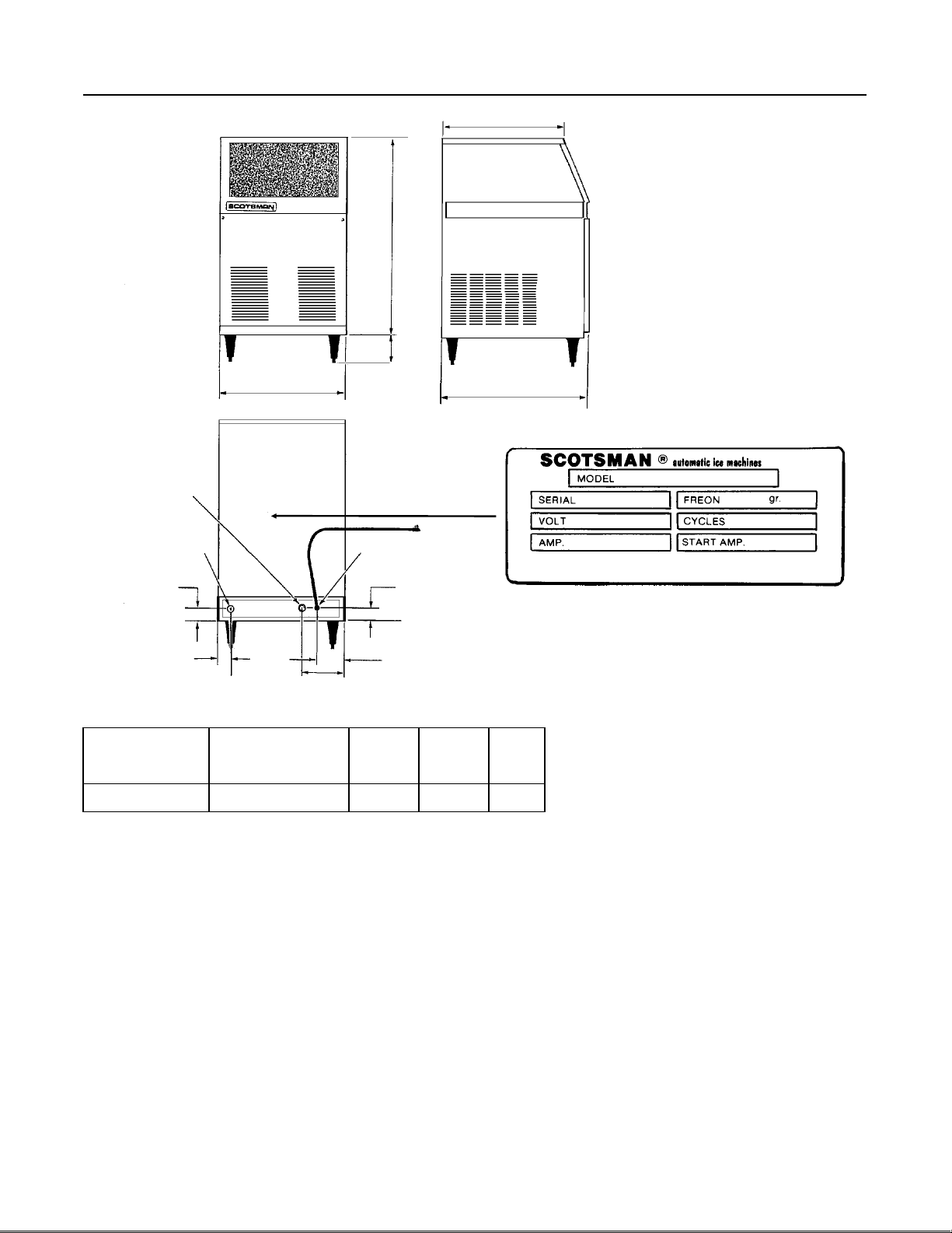
SPECIFICATIONS
17 9/16"
28.42"
5.5"
18"
3/4" HOSE COUPLI NG
THREAD
25/32"
1 .76"
5
.4"
POWER
3.83"
SPECIFICATIONS
Model Number Dimension s
H" X W" X D"
CS60MAS-1A 28.42 X 18 X 20.6 Medium 115/60/1
Cube
Size
The finish is stainle ss st eel. Minimu m circu it
ampacity is used to determin e wire size per
national elec tric code. Refrig eran t ty pe is R-22.
2 .2"
Basic
Electrical
20.6"
NAMEPLATE LOCATION
Max.
Fuse
Size
15
Refrigerant Charge is 12 oz of R-22.
Always go by the namepate.
OPERATING REQ UIRE MENT S:
MINIMUM MAXIMUM
0
Air Temperature 50
Wate r Temperatu re 40
F. 1000 F.
0
F. 1000 F.
Water Pressure 20 PSIG 100 PSIG
Voltage 103.5V 126.5V
Scotsman Ice Systems are designed and
manufactu re d with the high es t regard fo r sa fety
and performance. They meet or exceed the
standards o f UL and NSF.
Scotsman assu mes no liability or resp onsibilit y
of any kind for products manufactured by
Scotsman tha t have been altered in any way,
including the use of any parts and/or other
components not specifically approved by
Scotsman.
Scotsman reserve s th e right to make design
changes and/or improvements at an y time.
Specification s and designs are subject to
change without notice.
January 1995
Page 2
Page 3
FOR THE INSTALLER
CS60
Location:
Prior consideration for the location shall inc lud e:
••Indoors, with a minimum room tempe ratu re of
0
F. and a maximum room temperature of
50
0
F.
100
••Water tempera tu re to the machin e sh ou ld be
betwee n 40
0
F. and 1000F.
•• Service Access. Allow enough space at the
back of the cabinet for the utilit ies to be
connected. Allow enough space for the
machine to be pulled out from its ins talled
location. Do not build a floor in front of the
machine that would preve nt its remov al.
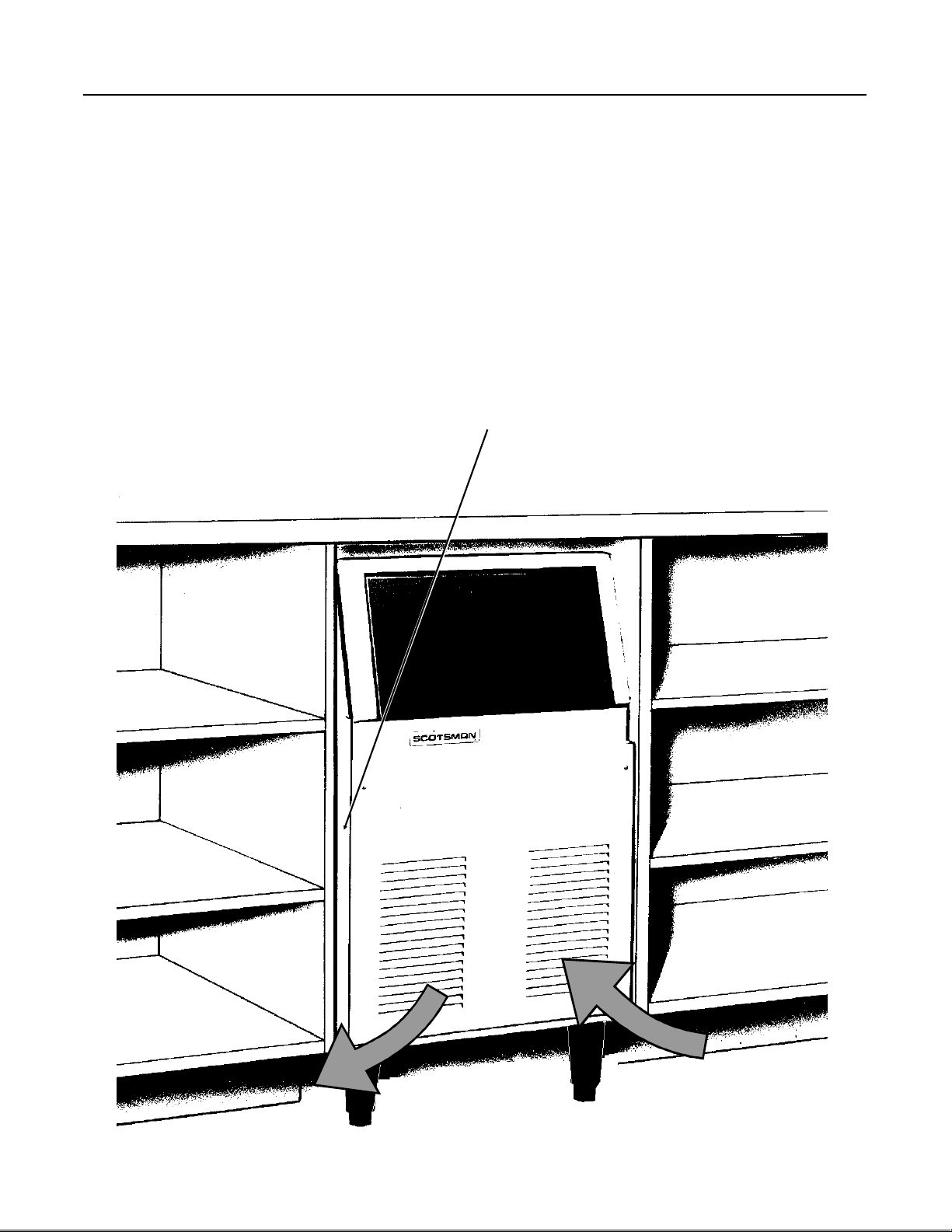
••Air circulation: The front pane l MUST remain
unobstruct ed . Do not blo ck with any type of
door or curtain .
If the unit is built in, it will pull air in from the right
side of the front panel, and exhaust it out the left
side of the front panel. If the left side of the
machine is left open, warm air will be
discharged from th e left sid e panel.
IF BUILT IN, THIS SIDE
SHOULD BE TIGHT AGAINST
THE CABINET T O PREVENT
AIR RECIRCULATION
WARM AIR DISCHARGE
COOL AIR INTAKE
January 1995
Page 3
Page 4
CS60
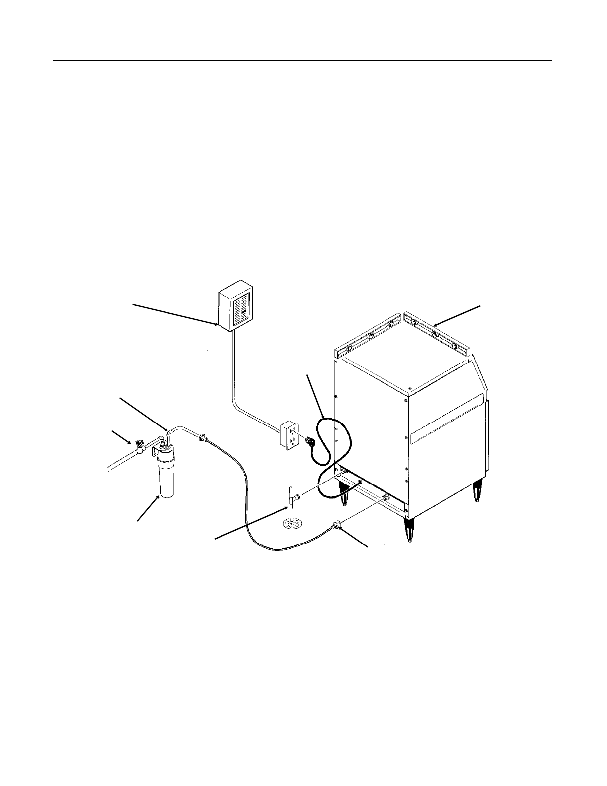
FOR THE PLUMBER
Wat er sup ply an d dra in conne ct ions.
1.The recomme nd ed water supp ly line is a 1/4"
o.d. coppe r tube , th e water pressure must have
a minimum incoming pressu re of 20 psig.
2.Con ne ct th e tubin g to the 3/4 " hose cou plin g
thread water inlet fitting at the back of the ice
maker. An optional adapter to go from the 3/4"
hose coupling thread to 1/4" compression fitting
is available fro m your de ale r under p art numbe r
0533238.
Or a similar adapter can be purchased from a
hardware store.
POWER
SUPPLY
3.Install a shut off valve in the incoming water
line near the ice maker so that the water can be
shut off for service.
4.Con nect a gra vity drain line to the dra in
connection at the ice ma ker. A minimum slope
of 1/4" fall per foot of horizontal run is
recommended. Install th e drain s per the loc al
codes.
A vent is reco mmended on the highest poin t of
the drain tube , and th e drain tubing mu st be
rigid pipe. Do NOT use flexible tubing.
LEVEL THE
UNIT
POWER
CORD
WATER
SUPPLY
SHUT
OFF
WATER FILTER
(FIELD SUPPLIED)
DRAIN
ELECTRICAL
1.Locat e th e namep lat e on the lower re ar pane l
and check tha t the locat ion sou rc e volt age an d
capacity are correct for this unit . The unit is
equipped with a grounded plug connection .
Under no circumstan ces must the gro und post
be altered or removed.
Extensio n cords are not pe rmitt ed.
ADAPTER
(FIELD SUPPLIED)
Be certain that the ice make r is conn ect ed to its
own electrical circuit and is individu ally fused.
The maximum allowable volt age varia tio n
should not exceed ten percent of the nameplate
rating.
All external wirin g shou ld co nform to the
National, State, and local electrical code
requirements. Usually an electrical permit and
the services of a licensed electricia n will be
required to install the receptacle.
January 1995
Page 4
Page 5

INSTALLATION
CS60
FINAL CHECK
1.Is th e Cab ine t level?
2.Have all the electrical and piping connections
been made?
3.Has th e voltage been teste d and ch eck ed
against the nameplate rating?
4.Is th e unit plu gg ed into a sep arat e ele ct ric al
circuit?
5.Is the wat er sup ply line shut of f valv e inst alle d
and is the water turned on?
POWER?
6.Have the bin interior, and the cabinet exterior
been wiped clean?
7.Are all int ern al pa rt s in pla ce, including the
spray platf orm a nd curtain?
8.Have the internal refrigerant lines been
checked for rubbing and chaffing?
9.Has th e machine been installed where it is
indoors, in a cont rolled env ironme nt , with
adequate air circulation around the machine,
and where it can be serv iced ?
LEVEL?
DRAINS?
WATER?
January 1995
Page 5
Page 6

CS60
INITIAL START UP
1.Open water supply valve.
2.Move electrical breaker or switch to the on
position.
3.Remo ve fro nt panel.
4.Che ck th e cube size control sh af t, it shou ld be
in a preset cube size posit ion . If not, turn it
clockwise until the unit comes on. Note: cube
size adjust men ts may be required . St art with the
shaft in the "mid" posit ion.
5. The machine will go thru a "dry" cycle, this will
take about 10 minutes. Th en the water f ill and
harvest cycle will begin.
6. Observe the water fill cycle:
••The water inlet valve opens .
••Incoming wate r flows from th e valve th rou gh
the tubing to the top of the ice maker.
••Water flows around the inverted ice cube
cups an d drains through holes into the
reservoir.
•• The reservoir begins to fill up with water.
••Water continues to enter the machine and
overflows a stan dpipe in the reservo i r and
dow n the dr ain.
1
This will take about 3
freeze cycle will begin.
7.Che ck th e operat ion of the fre ezin g cyc le:
⁄2 minutes. Af te r th at th e
If the cu bes are overfilled, adjust the machine to
make smaller ice cubes by turnin g the cube size
control counter-clockwise.
In both cases , th e ne xt cyc le of cube s harv ested
must be observed, and further corrections may
be needed.
If the ice cubes are cloudy, an extreme water
condition may exist. Confirm that they are
cloudy by pla cing them in a glass of co ld water.
If, in the water, they remain cloudy, you may
want to have the water tested by a water
treatment specia list.
If the ice cubes are cloudy only on the bottom or
in the center, the machine ma y be running out of
water before the end of the fre ezin g cyc le.
10. Test the bin full shu t of f. To test this, ho ld
some ice on the bin thermo sta t bra cke t (t he
stainless steel tube on the left side of the ice
storage bin ). The ice maker sho uld stop within a
few minutes of having ice on that tu be.
1 1 . Fill out the W a rra nty Re gis trat ion and
Customer Evaluation form, and mail both to
Scotsman.
12. Make sure the user unders tand s the
operatio n and mainte na nce requ i remen ts for the
ice maker. Leave the service manual and the
name of the local Scotsma n service agen cy with
the us er.
••Compressor is running.
••Water pump is spraying water through the
spray nozzles.
••Ice making begins, the wat er gets very co ld,
and ice begins to form in the cube molds.
8.Che ck th at the plast ic curt ain asse mbly ha ngs
down evenly in the openin g and that no larg e
streams of water are pa ssin g throug h.
Note: Some wate r will drip from the reservo i r as
the machine runs. This is normal.
9.Afte r about 20 minut es the machin e will begin
to release the ice , th is is called the harve st cy cle.
Observe the first cube harvest:
••Check the size of the ice cubes.
Note: The normal size of the ice cube has a 1/4"
depressio n in the wide end.
If the cu bes are not filled out, adjust the machine
to make larger ice cu bes by tu rning the cube
size control shaft cloc kwise .
January 1995
Page 6
Page 7

HOW IT WORKS:
CS60
COMPONENT DESCRIP TI ON
Cube Size Control
The cube size control is loca te d in front of the
control box, behind the fron t pa ne l. Th e se nsing
capillary tube of the cube size control is routed
out of the control box int o its bulb ho lde r on the
evaporator coil. It is a reverse acting
temperat ure cont rol with doub le throw con ta ct s.
Turn ing its knob all the way coun terc lock wise
also shuts off the ice maker.
The control det ermine s th e len gth of the
freezing cyc le and corres pond ing ly the size of
the cube. A lo wer settin g will produce a smaller
cube, and a higher setting will make a large r
cube. The cube size control changes its
contact s whe n th e eva po rat or reaches its preset
temperature, starting the harvest cycle. When
the sensing tu be of the cu be siz e control
reaches th e hig h pres et temp erature, the
contact s cha nge again, restarting the freez e
cycle.
Compressor Toggle Switch.
The compressor toggle switch is located on the
side of the control box. When move d to the ON
position, it make s a circuit to the compres sor.
When moved to the OFF posit ion , th e other
components will still operate.
Water Pump
The water pump operates during the fre ez ing
cycle only, pumping water thro ug h the spra y
nozzles int o the inve rte d spra y cups.
Inlet Water Solenoid V al ve
The water sole no id valv e, locat ed in the bac k
panel of the unit, is energized only durin g the
harvest or cleaning cycle s. When energized it
allows a metered amou nt of wat er to flow int o
the machine (.21 g.p.m.) This water flows to the
top of the evaporator and then down into the
reservoir.
Bin Thermostat Control
The bin thermo st at control bo dy is loca te d in
front of the control box just beside the cube
size control. The thermos ta t se nsin g tub e is
located in the ice storage bi n on the lef t side wall
where is automa tic ally sh uts the ice make r of f
when the bin is full and rest arts when ice is
removed. Factory settings are 1 degree C (36
degrees F) cut out and 4 degrees C (39 degrees
F) cut in. It can be adjusted by turning the
adjustment screw visible through the contro l box
cover.
Hot Gas V alve Assem bly
The hot gas valve assembly is comprise d of two
parts, the valve body and the coil. These p arts
are located on the discharge line of the
compressor and are activated by the cube size
control (harvest cyc le). When the coil of the hot
gas valve is energized, it magn etically lifts the
plunger in the hot ga s valve body. This allows
hot refrigerant gas to by-pass th e co nden ser
and go directly to the evaporator.
Spray Pla t form and Chute
The spray syst em use d on this unit is of the
station ary typ e. The water is forced by the
water pump into the pla tf orm chambe r and
spraye d int o the inve rte d cup mo lds throu gh a
set of six spray nozzles.
Fan Motor
The fan motor is electrically connec ted through
the cube size control and runs only durin g th e
freezing cyc le.
Hermetic Motor Compressor
The compress or is a vapor pump , fo rcing
refrigera nt gas throu gh ou t the refrigeration
system.
January 1995
Page 7
Page 8

WATER
PUMP
HOT GAS
VALVE
CUBE SIZE
&
ON/OFF
CS60
COMPONENT LOCA T IO N
SPRAY PLATFORM
EVAPORATOR
RESERVOIR
FILL TU BE
WATER RESERVOIR
BIN LE VEL
CONTROL
TUBE
BIN DRAIN
BIN
THERMOSTAT
CONTROL
BOX
WATER
INLET
VALVE
COMPRESS OR
CLEANING
SWITC H
January 1995
Page 8
Page 9

HOW IT WORKS:
CS60
WATER
Freezing cycl e
The refrigerat ion proce ss crea te s cold
temperatures within the evaporator coils and
removes heat from the wat er spra yed up into
the inverted ice cube cup s. When enough heat
is removed, the wat er cha nges into ice, and
forms where it is the coldest: in the ic e cube
cups.
Minerals contain ed in the supply wat er will not
freeze and are drained away. Mostly pure water
will be frozen into the ice cubes.
During the freezing cycle , the compres sor, fan
motor, and water pump are operatin g. Wa te r is
continuou sly free zing or being sprayed and
recirculated. When evapora tor temperature is
lowered to th e cold temp era tu re set tin g of the
cube size control, it ends the freezin g cyc le an d
starts the harvest cycle.
Harvest cycle
The hot gas valve opens an d hot
refrigera nt gas is disc ha rged into the
evaporat or.
The inlet water valve opens an d a fresh
supp l y o f wa ter flows t o th e top of the
evaporat or and th en drains into the
reservoir.
WATER
SPRAY
WATER
PUMP, ON
DURING
FREEZE
The cube size control th ermo stat senses the
warmer temperat ures of the harv est cycle , an d
at a preset temperature, opens the circuit t o the
hot gas and inlet wat er valve s. Bot h valves th en
close.
The harvest cycle is comple te , and the free zin g
cycle restarts .
The automatic ic e making pro ces s con tin ues
until the bin is full of ice, and the bin thermostat
senses a cold er te mpe ra tu re.
The bin thermostat then opens the circuit to all
components and the automatic ice making
process stops.
WATER TO
EVAPORAT OR
The ice cubes hav e been releas ed
from the inverted cube cups in the
evaporator by th e warming eff ec t of the
hot refrig era nt gas co nd ensing in the
evaporator tu bin g, plus the inc omin g
water flowing aroun d the inv erted cups.
The release d ice cu be s drop ont o the
spray platf orm a nd thro ug h the curt ain
assembly int o th e ice st orag e bin .
INLET
WATER
VALVE, OPEN
DURING
HARVEST
DRAINS
January 1995
Page 9
Page 10

CS60
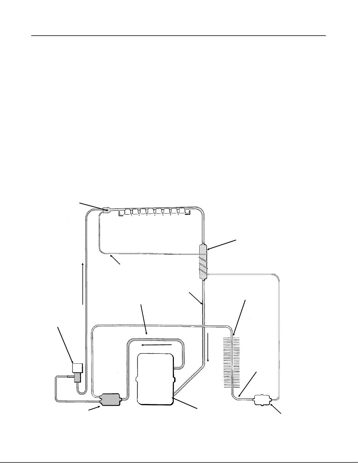
HOW IT WORKS:
FREEZE CYCLE
REFRIGERATION
The ice cubes are forme d in an inve rt ed mold
that is refrigerated.
The refrigerat ion proce ss be gin s at the
compress or. The re, ref rige rant vap or is
compressed and flows from the compressor
throug h the discharge line as a high
temperature, high pressure g as. In the
discharge line th ere is a stra ine r with two
outlets , on e lea ds to the cond enser, and one to
a solenoid valve . Be cause the solenoid valve is
closed, the gas flows to the condenser, where
heat is transferred from the ref rigera nt to the air
passing throu gh the con de nse r. The refrigerant
then condenses into a high pressure liquid.
EVAPORAT OR
From the condenser, the liquid refrigerant flows
throug h the liquid line , and the liqu id line
filter-drier. Af ter t he filter drier, the liquid
refrigerant enters the metering device, a
capillary tube. Af te r pas sing the restriction of
the capillar y tube, the refrigerant enters an area
of relative low pre ssu re, th e ev ap orator. In the
tubing of the ev aporator, the liquid refrigerant
expands and evaporates, absorbing heat from
the evaporat or tu bing and anything in contact
with it such as water sprayed against it.
The refrigeran t, now a low pressure, low
temperat ure va por, flows into the accumul ator,
which traps exc ess liquid refrigerant. The vapor,
now primarily a gas, goes through the suction
CAPILLARY TUBE
DISCHARGE
LINE
SUCTION
LINE
ACCUMULATOR
CONDENSER
LIQUID
LINE
STRAINER
Refrigeration System Schematic
January 1995
Page 10
COMPRESSOR
FILTER-DRIER
Page 11
HOW IT WORKS:
CS60
REFRIGERATION
HARVEST CYCLE
(When the cubes are released)
The ice cubes hav e be en formed in an inv erte d
mold that was refrigerated.
Now the refrigeratio n system will c hange to
warm the cube mold and release the cubes.
The process begins at the comp ressor. There,
refrigerant vapor is compress e d and flows from
the compressor through the di scharge line as a
high temperature, high pressure gas. Before
the gas gets to the con de nse r,it goes throu gh a
strainer, the strainer outlet is connected to two
tubes, one of which lead s to an electric va lve,
the hot gas sol eno id. When this valve opens,
the refrigerant gas follows the path of least
resistance and flows through the tu bing from the
EVAPORATOR
hot gas valve to the evapora tor, where the ice
cubes are frozen.
At th e evap orat or, th e high te mperature gases
are cooled by the cold te mpe rat ures of the cube
mold, and cond ense int o liqu id, transfer rin g heat
to the mold which warms up and releases the
cubes.
The refrigeran t, now a low pressure, low
temperat ure va por, flows into the accumul ator,
which traps exc ess liquid refrigerant. The vapor,
now primarily a gas, goes through the suction
line tub e to the compressor where the cycle is
repeated.
HOT GAS
SOLENOID
(OPEN)
CAPILLARY TUBE
DISCHARGE LINE
SUCTION
LINE
ACCUMULATOR
CONDENSER
LIQUID
LINE
STRAINER
COMPRESSOR
FILTER-DRIER
January 1995
Page 11
Page 12

CS60
OPERATI ON & ADJ UST MENT : OP ERA TI NG CHA RACT E RIS T ICS
The informat ion sho wn below cov ers a wide range of air and water temperatures. It is intended as a
guideline only, and is based on data compile d from NE W CLE AN un its . Allo w a varia tio n fro m eac h end
of the range given .
A. Refrigeration system pressures:
High Side (discharge)
End of Freeze cycle 150 - 160 psig
Harvest cycle 100 - 125 psig
Low side (suction)
End of Freeze cycle 10 - 11 psig
Harvest cycle (ma ximu m )90 psig
ADJUSTMENT OF THE CUBE SIZE :
Adjust only when cubes are too big or small.
(See the illustration at the right.)
1. Remove fron t pane l, loc at e kno b.
2. To increase th e size, turn knob 1/8 turn
clockwise. To make the cubes smaller, turn the
knob 1/8 turn counterclockwise.
B. Freeze cycle time 20 minutes
C. Defrost cycle time 2- 3 minutes
D. Compressor amp s
Freeze cycle 4 to 3.4
Harvest cycle 3.8 to 4.1
3. Observe the size of the cube s in th e next two
harvest cycles, if more adjust men t is neede d,
continue adjustments until the correct size is
obtained.
ADJUSTMENT OF THE BIN THE RMOS TA T
CONTROL
Adjust the bin thermostat when the ice maker
turns off too soon (ice level low) or when it turns
off too late (ice storage bin overfills.)
To increase the ice lev el in th e sto rag e bin :
Rotate the bin thermostat adjustment screw
(located under front panel on control bo x cov er)
clockwise one eight turn at a time until the ice
level that the machin e main ta ins is correct.
To decrease the ice level in the storage bin:
Rotate the bin thermostat adjustment screw
counterclock wise one eight turn at a time until
the ice level is correct.
CORRECT SIZE
TOO SMALL, L ITT LE OR NO
ICE IN THE CENTER OF THE
TOO BIG, THICK BULG E OF
SOLID ICE ON THE END.
January 1995
Page 12
Page 13

CS60
SANITIZ ING AND CLE A NING
A Scotsman Ice Syst em represents a sizable investment of time and money in any comp any’s
business . In order to rece ive th e best return for that invest men t, it MUS T rece ive pe riod ic maint en ance.
It is the USER’S RESPONS IB IL ITY to see that the unit is properly maint ain ed. The followin g is a list of
recommended main tena nce that will help keep the machin e running with a minimum of pro ble ms.
Maintenance and Clea ning should be schedule d at a minimum of twice per year.
General
The periods and pr ocedures for maintenance
and cleaning are given as a guide. Cleaning will
vary depending upon local water con dit ions and
the amount of ice used. Each ice maker must
be maintained individually, in accordance with its
own requirements.
Icemaker In Place Cleaning
1.Remo ve th e ice from the bin.
2. Remove front pa nel.
3. Rotate control knob counter clockwise to the
Off position.
4.Remo ve curtain by pulling forward on the left
end, and then pulling the curtain to the left and
out of the machine.
5.Lif t up spray platf orm, locate stand pipe to the
right of the opening, and pull it out to drain th e
reservoir. Replace the standpipe, s pray
platform, an d curtain.
1
6. Mix approximately 3 ounces (
Scotsman Ice Machin e Clea ne r with 1.5 quarts
(1.5 liter) of warm (95 -115
pour this solution into the reservoir at th e curt ain
base.
o
⁄10 liter) of
F.) potable water, and
Scotsman Ic e
Machine Cleaner
contains ac ids.
These comp ou nd s
may cause burns. If
swallowed, DO NO T
induce vomiting.
Give large amoun ts of
water or milk. Call
Physician
immediately. In case
of extern al contact,
flush with water.
8. Then switch the cleanin g togg le swit ch to the
"cleaning" po sitio n for abo ut three min utes to
release all the ice cubes from their cups.
9. Switch the cleanin g toggle switch to the
"operation " p osit ion , an d allo w the ma ch ine to
run for 30 minutes, or until the next batch of ice
is rele a sed into the bin.
10. Pour hot water into the bin to melt the ice
produced during cleaning, an d to clean ou t the
drain. Wipe the interior of the bin with mild soap
and hot water, rinse with cold water .
To sanitize, mix a locally ap proved sanitizer
solution and repeat steps 3-10, except
substitute the sanitizer solution for the ice
machine clean er so lut ion . A possible sanitize r
solution may be obtaine d by mixing 1 ounce of
household bleach with 2 gallons of warm
(95-115
Caution: Do not use the ice produced during
cleaning , as it may have a stron g ac id content.
11. Replace th e front panel.
Ice maker Maintenance
1.Shut off wat er sup ply to the ice mak er.
2.Disconnect the water inlet tu be from the
connect ion at the back of the ice make r, and
check the screen at that point. If very dirty,
carefully pull the screen out and clean it.
Reassemble water line to ice maker.
3.Open the water shut off valve.
4.Unplug the power cord to disconnect electrical
power to the ice maker.
5.Remo ve th e fro nt panel.
6.Clea n the air-coo led con dense r fins us ing a
vacuum, whisk broo m, brush, or if needed, coil
cleaner. The ice making cap ac ity o f thi s
machine is reduced by a dirty condenser coil.
o
F) water.
7. Rotate the control kn ob to the "norma l "
position . Operate the machine for 20 min ut es .
January 1995
Page 13
Page 14

CS60
SERVICE DIAGNOSIS
SYMPTOM POSSIBLE CAUSE SUGGESTED CORRECTION
Unit will not run Blown fuse or breaker Replace fuse & check for cause
of blown fuse, reset breaker.
Compressor cycles intermittently Low voltage Check voltage at the supply to
the building.
Check circuit for overloading.
Dirty condenser Clean the condenser
Air circulation blocke d around
unit
Non condensable gas in system Evacuate and recharge with
Cubes too small Cube size control set too warm Check and adjust for prope r
Partially restricted cap tube Blow charge, evacu ate with new
Moisture in system Same as above
Overcharged Same as above
Undercharged Same as above , look for a leak.
Cloudy cubes Spray nozzles plu gged Clean
Needs cleaning Clean with Scotsman Ice
Irregular size cubes, some
cloudy
Cubes too large Cube size control set improp erly Check and adjust fo r proper
Decreased ice capacit y Inefficien t comp ress or Re pla ce
Low Ice Capacity Leaky inlet water Replace valve
Some jets plugged Clean jets
Shortage of water Check wat er supply
Non-conde ns ab le gas in the
system
High Head Pressure Dirty condenser,
High air temp Relocate machine or water line.
Overcharge Repla ce th e ref rig era nt
Restricted syste m Replace the drier and refrigerant
Allow sufficien t air arou nd unit
nameplat e charge
operation
drier, weigh in nameplate charge
Machine Clea ner
operation
Replace refrigerant
Worn fan motor,
High air tempera ture
High water temperature
January 1995
Page 14
Page 15

CS60
SERVICE DIAGNOSIS
SYMPTOM POSSIBLE CAUSE SUGGESTED CORRECTION
Poor harvest Too short defrost Replace cu be siz e contro l
Not enough water Check water supply
Hot gas valve does not work Replace
Inlet wat er valve plugg ed Clean or replace
Air and water temp too low Try to change locatio n
No harvest Cube size control do es not work Replace
Hot gas valve does not work Replace
Water inlet valv e does not work Replace
Excessive wat er in ice st orage
bin
Drain plugged Clean drain
January 1995
Page 15
Page 16

CS60
REMOVAL AND RE P LACE M ENT
Electrical Shock Hazard.
Disconnect electrical
power before beginning.
Bin Thermostat
Cube Size Control
1.Unplug the ice maker to disconnect electrical
power.
2.Remo ve screws and cabine t top, front , and
rear panels.
3.Pull knob from cube size control shaf t.
Remove screws and control box cover to gain
access to th e cube size con tro l b ody. Remove
screws and dismount cube size control fro m
control box. Disconne ct ele ct ric al wi res from
cube size control.
1.Unplug the ice maker to disconnect electrical
power.
2.Remo ve scre ws and cabinet front panel.
3.Remo ve scre ws and con trol box cov er,
disconnect electrical wires fro m bin th ermos ta t
cont rol.
4.Dismou nt bin thermo sta t fro m the control bo x
5.Remo ve rea r pane l.
6.Pull bin th ermos tat capillary line from tube in
ice storage bin. Remove complete control from
ice machine.
7.Rep lace wit h new control in reverse order of
removal.
Cube Size Control Tube. Locate
and Secure in its Original
Position
4.At the top of the mach ine , un clip cube size
thermosta t tube hold er from ev aporat or, (retain
clips and tube assembly.) Pull cube size control
capillary tube from the tube, and remove
complete cube size co ntrol from th e ice maker.
5.Insert capilla ry tube on new thermo sta t int o
tube holder, be sure that the end cap s are in
place.
6.Reve rse th e remo val pro ced ure s to rein sta ll
the cube size control. Ad jus t as ne eded.
Refrigerati on Sy stem
Any time the refrigeratio n sys te m is opened, the
drier must be replac ed, the syst em ev acu ated
and th e exact charg e me a sured into th e s y s tem.
Any other procedure is NOT CORRECT, and will
result in subst an dard pe rforma nce .
January 1995
Page 16
Cube Size
Control
Page 17

INLET WATER
VALVE
REMOVAL AND RE P LACE M ENT
Electrical Shock Hazard.
Disconnect electrical
power before beginning.
CS60
Water Inlet Valve
1.Unplug the ice maker to disconnect electrical
power.
2.Shut off wat er sup ply to ice maker.
3.Remo ve th e lowe r back panel, pull out to
expose inlet wat er valve.
4.Disconnect electrical wires from inlet water
valve.
Spray Platform
1.Open ice bin door.
2.Pu ll out on the lef t side and remove curtain
assembl y.
3.Lif t th e spra y plat fo rm up and pu ll out to get to
the water hose at the base of the platform.
4.Pull hose off of conn ection to spray platform,
and pull platform from ice maker.
5.To replace, reve rs e the remov al procedures.
CURTAIN
5.Disco nnect water lines to and from wat er
valve.
6.Remo ve va lve fro m ice make r.
7.Reve rse remo val procedure to repla ce .
Water Pump
1.Disconnect ice maker from electrical power.
2.Remo ve to p panel.
3.Open ice bin door pull up through top and
remove.
4.Remove curtain by pulling forward and out on
the left end.
5. Remove 2 screws holding pump bracket t o
right side panel.
6. Disconnect 2 electrical leads and 1 ground
wire from pump.
7.Pull out spray platf orm, lift pump and
disconn ect hose.
8.Pull water pump up and out of ice maker.
9.Dismount water pump from cover assembly
(retaining the bra cke ts), and remoun t the
replacemen t pu mp in its place .
10. Reverse the bala nce of the st ep s to
reassemble .
January 1995
Page 17
 Loading...