

Page 1

CMS1402R SERVICE PARTS
This parts lists shows the service parts for the
CMS1402R Remote.
Check the model number of the machine to be
certain of obtaining the correct part.
A B model was introduced in early 1992. The major
differences between A and B are the front panels.
Included at the back of the parts list are the wiring
diagrams.
Table of Contents
Cabinet . . . . . . . . . . . . . . . . . . . . . . . . . . . . . . . . . . . . . . . . . . . . . . . Page 2
Refrigeration System . . . . . . . . . . . . . . . . . . . . . . . . . . . . . . . . . . . . . . . Page 3
Water System . . . . . . . . . . . . . . . . . . . . . . . . . . . . . . . . . . . . . . . . . . . Page 4
Control Box . . . . . . . . . . . . . . . . . . . . . . . . . . . . . . . . . . . . . . . . . . . . . Page 5
Remote Condenser . . . . . . . . . . . . . . . . . . . . . . . . . . . . . . . . . . . . . . . . . Page 6
BH900 Bin . . . . . . . . . . . . . . . . . . . . . . . . . . . . . . . . . . . . . . . . . . . . . . Page 7
Wiring Diagrams . . . . . . . . . . . . . . . . . . . . . . . . . . . . . . . . . . . . . . . . . . Page 8
August, 1993
Page 1
Page 2
4
7
ess
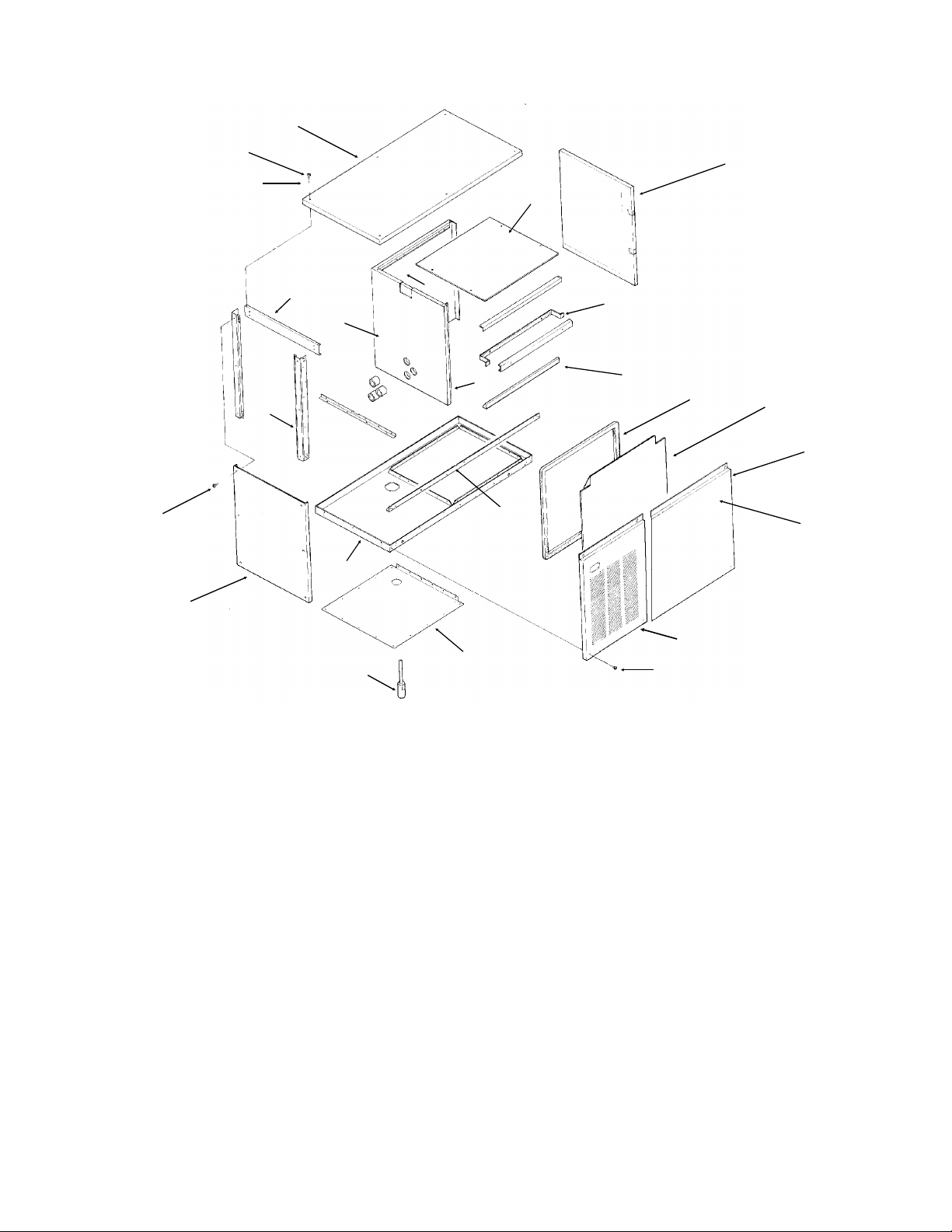
CMS1402R SERVICE PARTS
CABINET PARTS
3
1
2
21
17
20
1
14
18
6
15
10
5
8
9
11
12
16
23
ITEM PART
NUMBER NUMBER DESCRIPTION
1 03-1531-01 Screws
2 03-1417-27 Washers
3 A35074-001 Panel top (enamel)
A35074-002 Panel top (stainless)
4 A33364-001 Liner top
5 A29164-003 Right panel (enamel)
A29164-002 Right panel (stainless)
6 A29204-001 Brace front
7 02-2532-01 Liner cap
8 13-0595-00 Gasket (order per foot)
9 02-2795-01 Liner, front panel
10 03-1678-01 Speed clip (B model)
11 A35080-021 A model front panel (enamel)
A35080-022 A model front panel, (stainless)
A35401-022 B model right front panel, stainless
A35401-021 B model right front panel, painted
Front panels include insulation and liner.
03-1678-04 Thumb screw (B model)
24
22
13
03-1678-03 Screw retainer (B model)
02-3252-01 Plastic bumper (B model)
12 15-0711-01 Emblem
13 03-1404-19 Screws
14 A35110-001 Base assembly
15 02-2533-01 Liner, left side
16 A35075-001 Left side panel, enamel
A35075-002 Left side panel, stainless
17 no number Retainer
18 02-2531-01 Liner back
19 02-2534-01 Right side liner
20 A35069-001 Corner post
21 A35066-001 Brace
22 02-3151-01 Plastic cover
23 A34908-021 Transducer
24 A35400-001 B model left frnt pnl, painted
A35400-002 B model left frnt pnl, stainl
03-1678-02 Panel screw (B model)
02-3252-01 Plastic bumber (B model)
April, 1993
Page 2
Page 3
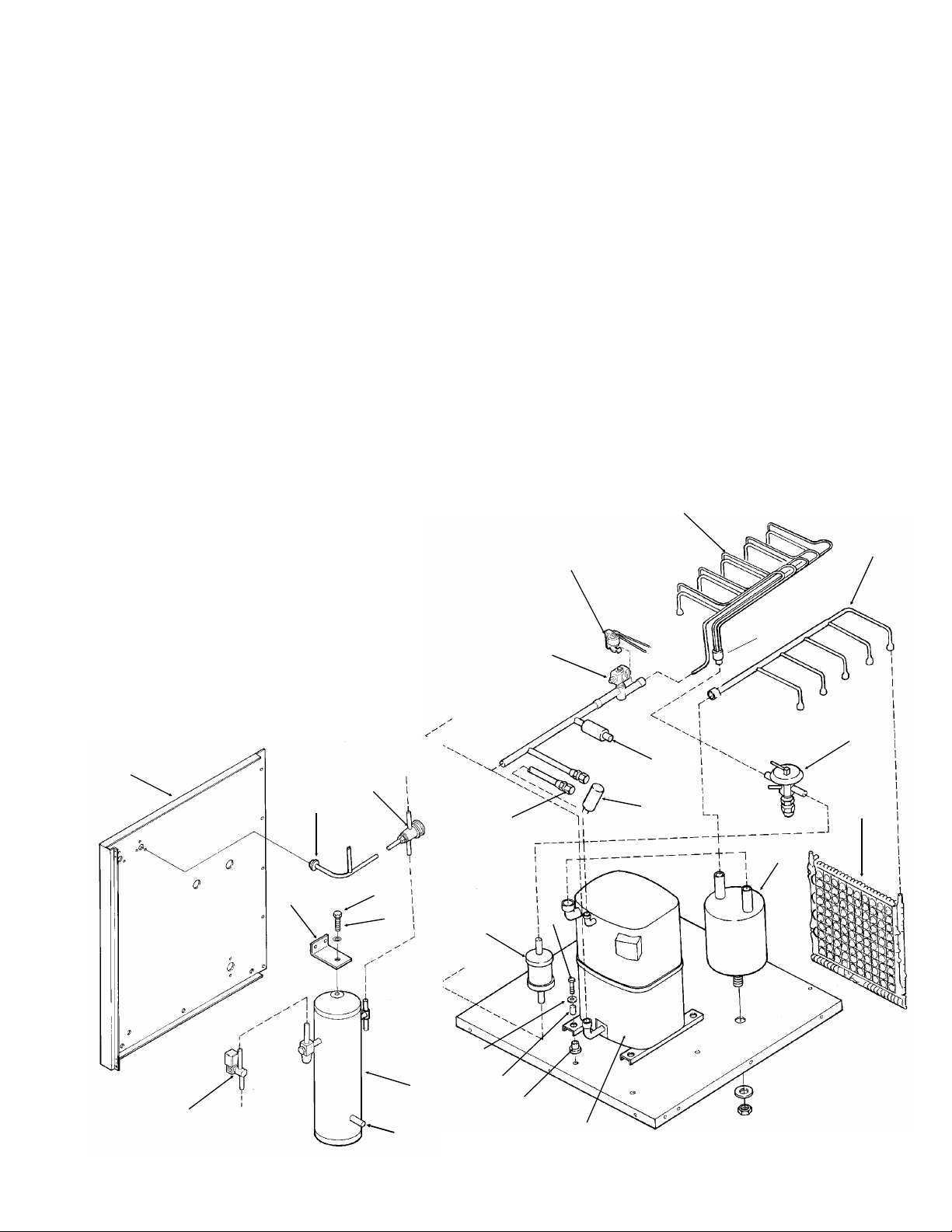
CMS1402R SERVICE PARTS
REFRIGERATION SYSTEM
ITEM PART
NUMBER NUMBER DESCRIPTION
1 A35122-001 Evap. manifold assy
2 A31816-001 Manifold assy
3 16-0816-21 Expansion valve
13-0617-51 O-Ring
02-2920-01 Foam insulation
4 12-2274-01 Liquid line solenoid valve
5 02-3319-02 Drier
6 16-0761-01 Receiver
7 A35072-001 Receiver bracket
8 03-1410-06 Lockwasher
9 03-1406-13 Nut
10 11-0422-22 Head pressure reg. valve
11 03-1405-20 Screw
12 03-1407-07 Washer
13 18-2200-28 Sleeve
14 18-5100-51 Grommet
15 12-2308-01 Crankcase heater
16 18-8864-22 Compressor, single phase
18-8864-21 Compressor, three phase
12-2309-01 Crankcase heater clip
18-2308-01 Crankcase heater
no number Comp. overload (internal)
ITEM PART
NUMBER NUMBER DESCRIPTION
17 12-2135-22 Hot gas valve
02-3231-03 Hot gas valve screen
18 16-0817-21 Accumulator
19 16-0560-00 Valve core
20 16-0563-00 Valve cap
21 12-2300-07 Hi temp cut out
22 A30296-020 Evaporator plate
23 16-0850-01 Discharge quick connect
24 16-0850-03 Liquid quick connect
25 A35070-001 Back panel
26 11-0446-25 Hi pressure cut out
27 11-0467-21 Pump down control
28 16-0790-01 Distributor, included in
item 1.
29 16-0823-01 Fusible plug
1
2
21
28
17
25
3
26
10
23, 24
19, 20
7
4
8
9
6
29
September 2004
11
5
12
13
14
16
Page 3
27
18
22
Page 4
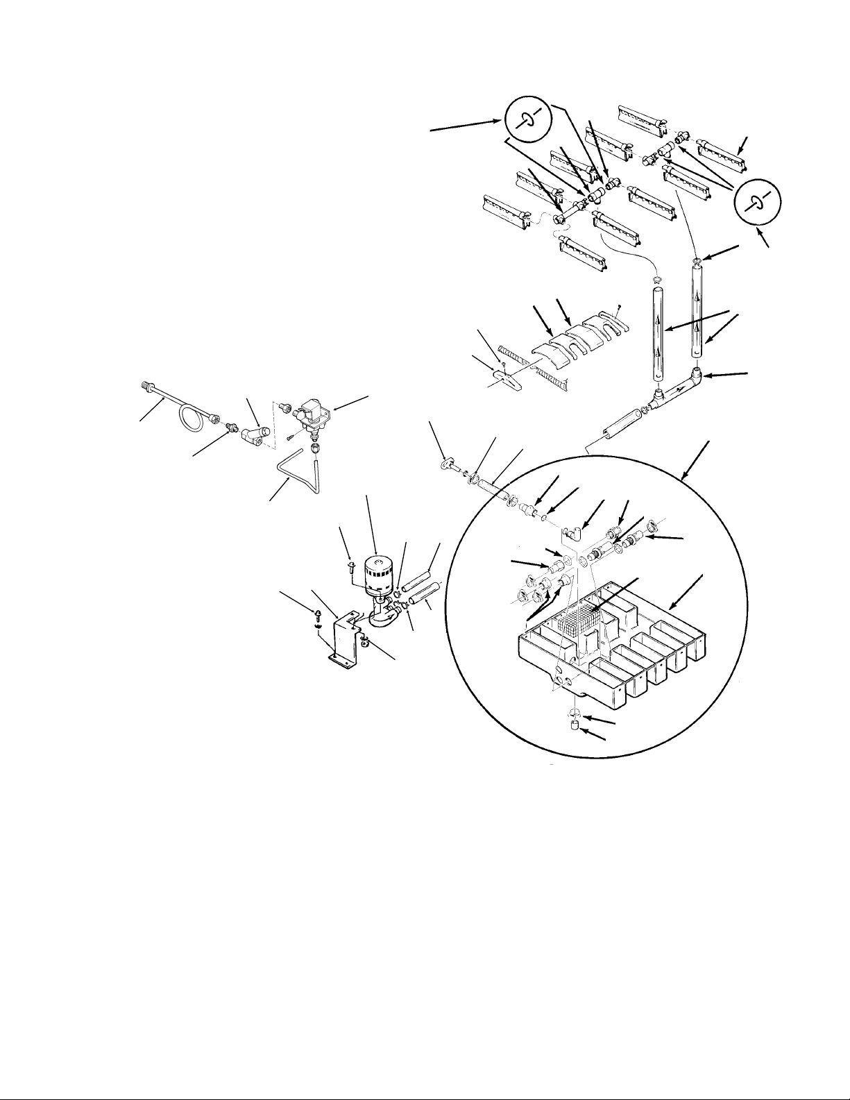
CMS1402R SERVICE PARTS
WATER SYSTEM
ITEM PART
NUMBER NUMBER DESCRIPTION
1 02-2521-01 Long water manifold
2 02-2519-01 Tee
3 A29703-001 Short water manifold
4 02-2527-01 Water dist. tube
5 02-2814-01 Clamp
6 A29730-001 Water Tube Assy
7 A30761-020 Sump Assembly
8 02-1530-01 Clamp
9 02-2814-12 Clamp
10 A30666-001 Pump Bracket
11 03-0571-01 Screw
41
39
40
43
11
11
10
12
42
3
18
17
13
20
22
8
23
35
1
14
21
36
15
2
25
26
27
28
29
30
37
31
4
5
18
9
6
7
12 12-2256-22 Water Pump
13 02-2523-01 End cover
14 02-2520-01 Sump cover
15 02-2520-02 Sump cover center
16 03-1407-05 Washer
17 03-1531-01 Screw
18 13-0617-48 O-ring
19 13-0674-07 Hose (18.5")
20 A32282-003 Drain
21 13-0674-07 Tube, drain (7")
22 02-2814-12 Hose clamp
23 13-0674-07 Tube, need 6.25"
24 13-0674-08 Tube, need 6.6"
25 02-2606-01 Female tube
26 13-0617-02 O-ring
27 02-2125-01 Elbow
28 02-2080-01 Overflow
29 02-2792-01 Pick Up tube
24
9
16
30 02-2793-01 Inlet tube
31 no number sump pan
32 02-1530-01 Clamp
33 13-0796-01 Rubber cap
34 02-2791-01 Water inlet nut
35 02-2606-01 Female tube
36 13-0617-02 O-ring
37 A30760-001 Screen
39 A35119-001 Water inlet assy.
40 16-0791-01 Half unio
41 16-0162-00 Strainer
42 12-1646-04 Inlet water valve
43 A35117-001 Tube
September 2004
Page 4
34
32
33
Page 5

CMS1402R SERVICE PARTS
16
2
1
4
11
22
ITEM PART PART
CONTROL BOX
15
17
21
6
19
20
18
14
9
NUMBER NUMBER NUMBER DESCRIPTION
3 phase single phase
1 - 18-1901-27 Start Capacitor
2 - 18-8702-01 Start Cap. Cap
3 - 03-1638-03 Screw
4 - 18-2200-39 Start cap. bracket
5 11-0351-22 same Cube Size Control
6 02-2242-02 same Stand off
7 12-1912-01 same Circuit board
8 12-1879-03 same Relay
9 12-2628-22 same Timer & Switch
10 12-0739-02 12-2469-02 Contactor
11 - 18-1903-28 Potential Relay
12 03-1403-17 same Screw
13 12-0426-01 same Comp. Switch
14 - 12-1213-12 Snap busing
15 - 18-1902-27 Run capacitor
16 - 13-0666-00 Terminal cover
17 - A34314-001 Run Cap Bracket
18 02-3173-01 same Swtich plate
19 12-2414-01 same Wash- Off - Ice switch
20 12-2411-01 same Bin ice level switch
12-2402-01 same Wire harness, bin level switch to board
21 12-2376-21 same Ice level control circuit board
22 12-2285-22 same Transformer
23 A35082-001 same Control box cover
September 2004
Page 5
10
5
12
13
7
8
3
23
Note: Replacement Single Phase
Compressor Starting Components:
Scotsman began supplying a new
replacement compressor in 2004, it uses
these starting components.
Item 1 same
Item 11 18-1903-58
Item 15 18-1902-60
The new replacement compressor is
Copeland number CR47KQ-PFV-280AB
Page 6

CMS1402R SERVICE PARTS
REMOTE CONDENSER
RC1422-32
ITEM PART
NUMBER NUMBER DESCRIPTION
1 02-2618-01 Fan guard
2 18-6304-01 Fan blade
3 18-5301-01 Fan motor
Not Shown:
4 16-0850-03 Quick connect, liquid
5 16-0850-01 Quick connect, discharge
6 16-1057-01 Quick connect, pre-charged 3/8" line
7 16-1057-02 Quick connect, pre-charged 1/2" line
September 2004
Page 6
Page 7

CMS1402R SERVICE PARTS
BH900 ICE STORAGE BIN
ITEM PARTS
NUMBER NUMBER DESCRIPTION
1 A35322-020 Canopy Assembly
2 A35152-001 Ice Baffle
3 02-2809-01 Drain Top
4 13-0617-11 O-ring
5 02-3201-01 Drain casting
6 KLP2E Leg Kit, Black
KLP2S Leg Kit, Nickel Plated
7 15-0711-01 Emblem
8 13-0595-00 Door gasket( 6.25’ reg.)
9 19-0503-04 Bin gasket
10 03-0727-11 Baffle screw
11 A35275-001 Door frame assy.
12 A35323-020 Door with gasket
13 03-1539-09 "E" ring
ITEM PARTS
NUMBER NUMBER DESCRIPTION
14 02-2380-01 Hinge bushing
15 02-3195-01 Door hinge
16 02-3196-01 Bin hinge
17 02-2806-01 Shoulder screw
18 02-2380-02 Spacer
19 03-1403-29 Screw 10-24
20 03-1403-24 Screw 10-24
22 02-0540-00 Scoop
August, 1993
Page 7
Page 8

CMS1402R SERVICE PARTS
208-230/60/3
Remote Air Cooled
April, 1993
Page 8
Page 9

CMS1402R SERVICE PARTS
208-230/60/3
Remote Air Cooled
August, 1993
Page 9
Page 10

CMS1402R SERVICE PARTS
208-230/60/1
Remote Air Cooled
April, 1993
Page 10
Page 11

CMS1402R SERVICE PARTS
208-230/60/1
Remote Air Cooled
August, 1993
Page 11
 Loading...