

Page 1

CMS1202 SERVICE PARTS
This parts lists shows the service parts for the
CMS1202 air cooled and the CMS1202 water
cooled.
Check the model number of the machine to be
certain of obtaining the correct part.
Included at the back of the parts list are the wiring
diagrams.
Table of Contents
Cabinet . . . . . . . . . . . . . . . . . . . . . . . . . . . . . . . . . . . . . . . . . . . Page 2
Refrigeration System . . . . . . . . . . . . . . . . . . . . . . . . . . . . . . . . . . . . Page 3
Air and Water Cooled Parts . . . . . . . . . . . . . . . . . . . . . . . . . . . . . . . . . Page 4
Water System . . . . . . . . . . . . . . . . . . . . . . . . . . . . . . . . . . . . . . . . Page 5
Control Box . . . . . . . . . . . . . . . . . . . . . . . . . . . . . . . . . . . . . . . . Page 6
BH900 Bin . . . . . . . . . . . . . . . . . . . . . . . . . . . . . . . . . . . . . . . . . . Page 7
Wiring Diagrams . . . . . . . . . . . . . . . . . . . . . . . . . . . . . . . . . . . . . . . Page 8
April, 1993
Page 1
Page 2
CMS1202 SERVICE PARTS
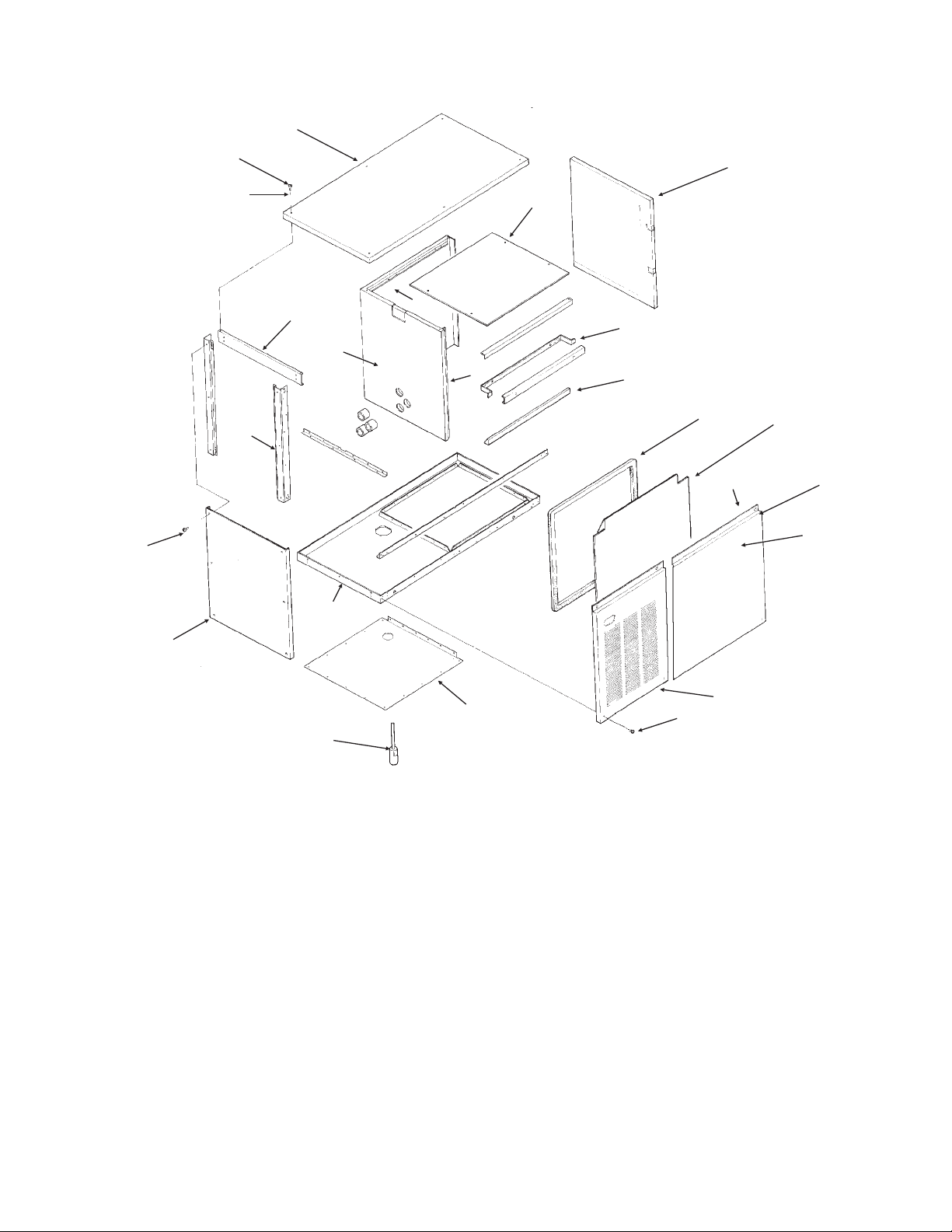
CABINET PARTS
3
1
2
21
17
20
1
18
15
4
6
7
5
8
10
9
11
12
14
16
ITEM PART
23
NUMBER NUMBER DESCRIPTION
1 03-1531-01 Screws
2 03-1417-27 Washers
3 A35074-001 Panel top (enamel)
A35074-002 Panel top (stainless)
4 A33364-001 Liner top
5 A29164-003 Right panel (enamel)
A29164-002 Right panel (stainless)
6 A29204-001 Brace front
7 02-2532-01 Liner cap
8 13-0595-00 Gasket (order per foot)
9 02-2795-01 Liner, front panel
10 03-1678-01 Speed clip (B model)
11 A35080-021 A model front panel (enamel)
A35080-022 A model front panel, (stainless)
A35401-022 B model right front panel, stainless
A35401-021 B model right front panel, painted
February 1998
22
13
Front panels include insulation and liner
03-1678-04 Thumb Screw (B model)
03-1678-03 Screw retainer (B model)
02-3252-01 Plastic Bumper (B model)
12 15-0711-01 Emblem
13 03-1404-19 Screws
14 A35110-001 Base assembly
15 02-2533-01 Liner, left side
16 A35075-001 Left side panel, enamel
A35075-002 Left side panel, stainless
17 no number Retainer
18 02-2531-01 Liner back
19 02-2534-01 Right side liner
20 A35069-001 Corner post
21 A35066-001 Brace
22 02-3151-01 Plastic cover
23 A34908-021 Transducer
24 A35400-001 B model left frnt panel, painted
Page 2
24
Page 3
CMS1202 SERVICE PARTS
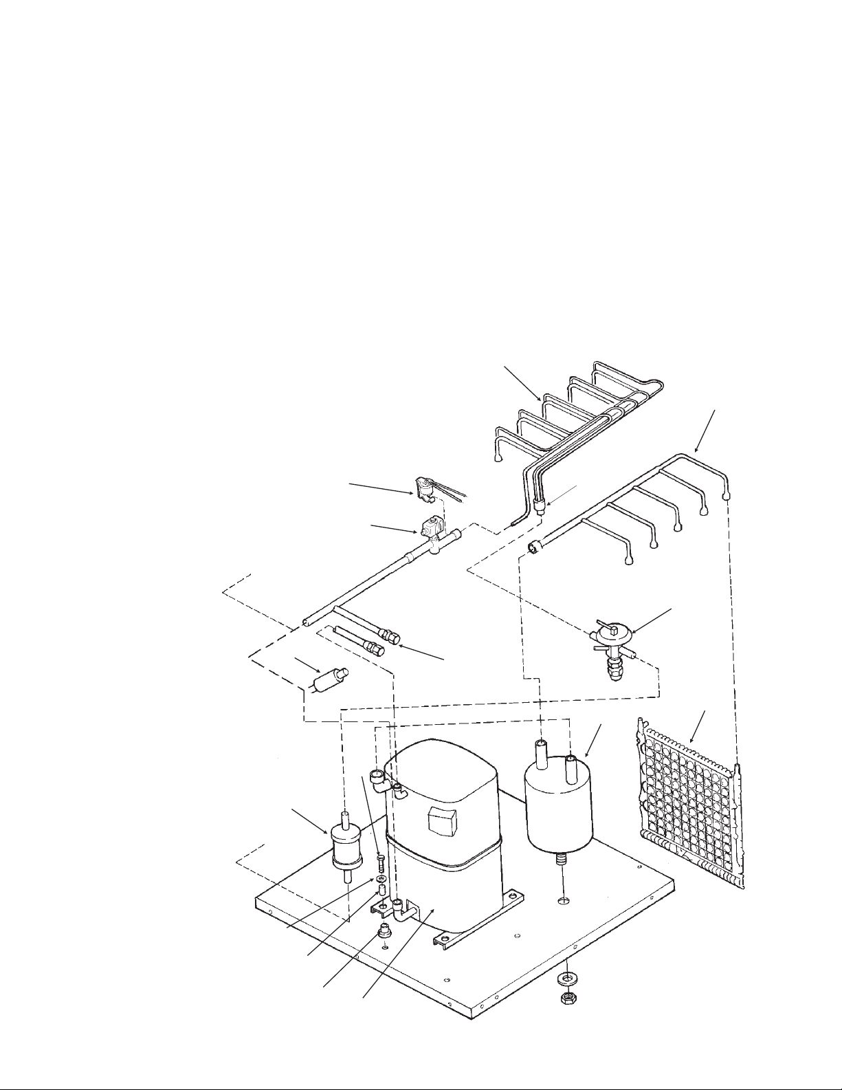
REFRIGERATION SYSTEM
ITEM PART
NUMBER NUMBER DESCRIPTION
1 A35122-001 Evap. manifold assy
2 A31816-001 Manifold assy
3 16-0816-21 Expansion valve
13-0617-51 O-Ring
02-2920-01 Foam insulation
4 02-2426-02 Drier
5 03-1405-20 Screw
6 03-1407-07 Washer
7 18-2200-27 Sleeve
8 18-2200-28 Grommet
9 18-8600-02 Compressor, single phase
(CRG3-0250-PFV-270)
18-8600-03 Compressor, three phase
(CRG3-0250-TF5-270)
no number Comp. overload (internal)
Replacement compressors include crankcase
heater, not used on this model.
14
ITEM PART
NUMBER NUMBER DESCRIPTION
10 12-2290-22 Hot gas valve
02-3231-03 Hot gas valve filter
11 16-0817-01 Accumulator
12 16-0560-00 Valve core
13 16-0563-00 Valve cap
14 12-2300-02 Hi temp cut out
15 A30296-020 Evaporator plate
16 11-0465-21 Hi press. cut out (A.C.)
11-0463-22 Hi press. cut out (W.C.)
17 16-0790-01 Distributor, included
in item 1.
1
2
17
16
10
3
12, 13
15
11
5
4
5
6
7
8
9
April, 1993
Page 3
Page 4
CMS1202 SERVICE PARTS
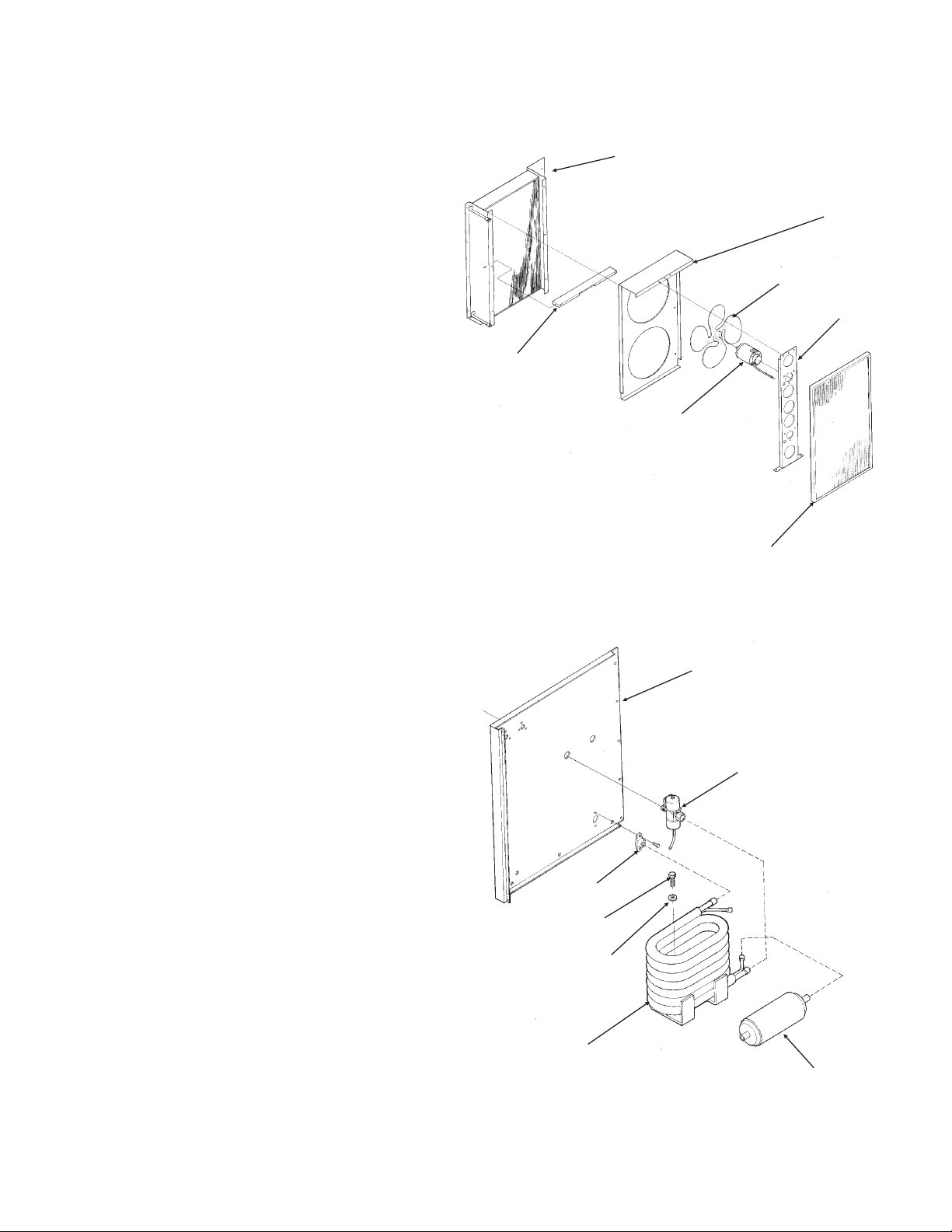
CONDENSING ASSEMBLIES
5
AIR COOLED MODELS
ITEM PART
NUMBER NUMBER DESCRIPTION
1 A35103-001 Fan Bracket
2 18-5105-02 Fan Motor
3 18-8503-01 Fan Blade
4 A35104-001 Condenser Shroud
5 18-8502-01 Condenser
6 02-3164-01 Filter
7 A35102-001 Condenser divider
WATER COOLED MODELS
ITEM PART
NUMBER NUMBER DESCRIPTION
1 11-0424-21 Water Regulator Valve
2 18-6302-01 Condenser, Water Cooled
3 03-1407-05 Washer
4 03-0571-01 Screw
5 A35070-001 Left back panel
6 02-2628-01 Receiver
7 A31828-001 Drain casting
4
3
1
7
2
5
5
1
February 1998
Page 4
7
4
3
2
6
Page 5
CMS1202 SERVICE PARTS
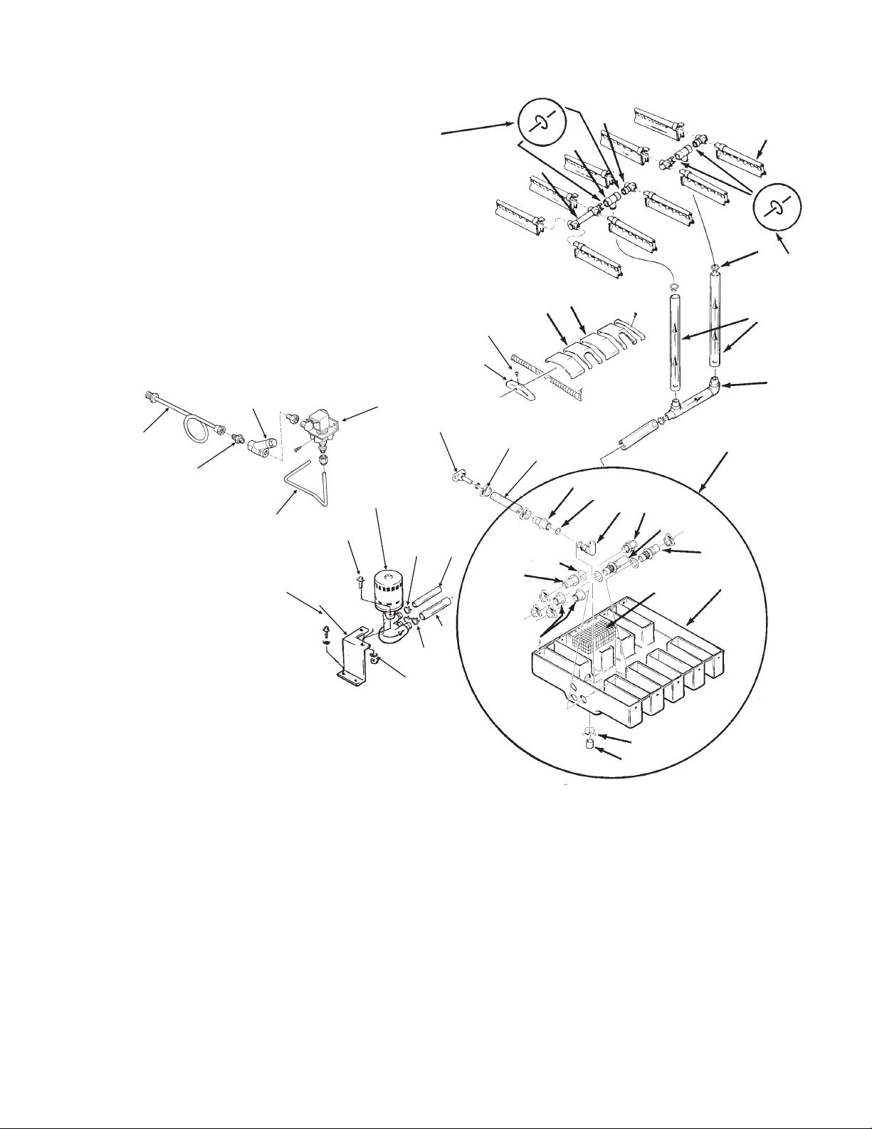
WATER SYSTEM
ITEM PART
NUMBER NUMBER DESCRIPTION
1 02-2521-01 Long water manifold
2 02-2519-01 Tee
3 A29703-001 Short water manifold
4 02-2527-01 Water dist. tube
5 02-2814-01 Clamp
6 A29730-001 Water Tube Assy
7 A30761-020 Sump Assembly
8 02-1530-01 Clamp
9 02-1800-01 Clamp
10 A30666-001 Pump Bracket
11 03-0571-01 Screw
41
39
40
43
11
11
10
12
42
3
18
17
13
20
22
8
23
35
1
14
21
36
15
2
25
26
27
28
29
30
37
31
4
5
18
9
6
7
12 12-2256-22 Water Pump
13 02-2523-01 End cover
14 02-2520-01 Sump cover
15 02-2520-02 Sump cover center
16 03-1407-05 Washer
17 03-1531-01 Screw
18 13-0617-48 O-ring
19 13-0674-07 Hose (18.5")
20 A31757-002 Drain
21 13-0674-07 Tube, drain (7")
22 02-2814-12 Hose clamp
23 13-0674-07 Tube, need 6.25"
24 13-0674-08 Tube, need 6.6"
25 02-2606-01 Female tube
26 13-0617-02 O-ring
27 02-2125-01 Elbow
28 A29342-001 Overflow
29 02-2792-01 Pick Up tube
24
9
16
April, 1993
Page 5
34
32
33
30 02-2793-01 Inlet tube
31 no number sump pan
32 02-1530-01 Clamp
33 13-0796-01 Rubber cap
34 02-2791-01 Water inlet nut
35 02-2606-01 Female tube
36 13-0617-02 O-ring
37 A30760-001 Screen
39 A35119-001 Water inlet assy.
40 16-0791-01 Half unio
41 16-0162-00 Strainer
42 12-1646-04 Inlet water valve
43 A35117-001 Tube
Page 6

CMS1202 SERVICE PARTS
16
2
1
4
11
22
ITEM PART PART
CONTROL BOX
15
17
21
6
19
20
18
14
9
NUMBER NUMBER NUMBER DESCRIPTION
3 phase single phase
1 - 18-1901-48 Start Capacitor
2 - 18-8702-01 Start Cap. Cap
3 - 03-1638-03 Screw
4 - 18-2200-39 Start cap. bracket
5 11-0351-22 same Cube Size Control
6 02-2242-02 same Stand off
7 12-1912-01 same Circuit board
8 12-1879-03 same Relay
9 12-1980-22 same Timer & Switch
10 12-0739-02 12-2469-02 Contactor
11 - 18-1903-46 Potential Relay (not illustrated)
12 03-1403-17 same Screw
13 12-0426-01 same Comp. Switch
14 - 12-1213-12 Snap busing
15 - 18-1902-27 Run capacitor
16 - 13-0666-00 Terminal cover
17 - A34314-001 Run Cap Bracket
18 02-3173-01 same Swtich plate
19 12-2414-01 same Wash- Off - Ice switch
20 12-2411-01 same Bin ice level switch
12-2402-01 same Wire harness, bin level switch to board.
21 12-2376-21 same Ice level control circuit board
22 12-2285-22 same Transformer
23 A35082-001 same Control box cover
February 1998
Page 6
13
10
5
12
7
8
23
The Fan Pressure Control is
located behind the control box.
11-0426-22 is the part number.
3
Page 7

CMS1202 SERVICE PARTS
BH900 ICE STORAGE BIN
10
1
2
13
20
12
14
19
15
18
17
16
11
9
8
7
6
5
3
4
ITEM PARTS
NUMBER NUMBER DESCRIPTION
1 A35322-020 Canopy Assembly
2 A35152-001 Ice Baffle
3 02-2809-01 Drain Top
4 13-0617-11 O-ring
5 02-3201-01 Drain casting
6 KLP2E Leg Kit, Black
KLP2S Leg Kit, Nickel Plated
7 15-0711-01 Emblem
8 13-0595-00 Door gasket( 6.25’ reg.)
9 19-0503-04 Bin gasket
10 03-0727-11 Baffle screw
11 A35275-001 Door frame assy.
12 A35323-020 Door with gasket
13 03-1539-09 “E” ring
ITEM PARTS
NUMBER NUMBER DESCRIPTION
14 02-2380-01 Hinge bushing
15 02-3195-01 Door hinge
16 02-3196-01 Bin hinge
17 02-2806-01 Shoulder screw
18 02-2380-02 Spacer
19 03-1403-29 Screw 10-24
20 03-1403-24 Screw 10-24
April, 1993
Page 7
Page 8

CMS1202 SERVICE PARTS
208-230/60/3 Air Cooled
February 1998
Page 8
Page 9

CMS1202 SERVICE PARTS
208-230/60/3 Air Cooled
April, 1993
Page 9
Page 10

CMS1202 SERVICE PARTS
208-230/60/1 Air Cooled
February 1998
Page 10
Page 11

CMS1202 SERVICE PARTS
208-230/60/1 Air Cooled
April, 1993
Page 11
Page 12

CMS1202 SERVICE PARTS
208-230/60/3 Water Cooled
February 1998
Page 12
Page 13

CMS1202 SERVICE PARTS
208-230/60/3 Water Cooled
April, 1993
Page 13
Page 14

CMS1202 SERVICE PARTS
208-230/60/1 Water Cooled
February 1998
Page 14
Page 15

CMS1202 SERVICE PARTS
208-230/60/1 Water Cooled
April, 1993
Page 15
 Loading...