

Page 1

INTRODUCTION
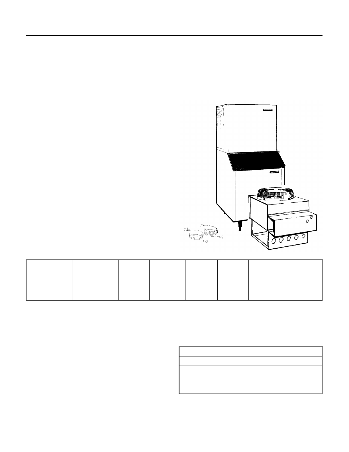
CME500R
To the owner or user: This service manual is
intended to provide you and the maintenance or
service technician with the information needed to
install, start up, clean, maintain and service this
ice system.
The CME500R uses HP62 as the refrigerant, and
polyolester oil for compressor lubrication.
Table of Contents
INTRODUCTION . . . . . . . . . . . . . . . . . . . . . . . . . . . . . . . . . . . . . . . . . . . . . . 1
FOR THE INSTALLER . . . . . . . . . . . . . . . . . . . . . . . . . . . . . . . . . . . . . . . . . . . 2
FOR THE INSTALLER: Remote Condenser . . . . . . . . . . . . . . . . . . . . . . . . . . . . . . . . 5
FOR THE INSTALLER: Coupling Instructions . . . . . . . . . . . . . . . . . . . . . . . . . . . . . . . 6
FOR THE ELECTRICIAN . . . . . . . . . . . . . . . . . . . . . . . . . . . . . . . . . . . . . . . . . 7
FOR THE PLUMBER . . . . . . . . . . . . . . . . . . . . . . . . . . . . . . . . . . . . . . . . . . . . 8
FINAL CHECK LIST . . . . . . . . . . . . . . . . . . . . . . . . . . . . . . . . . . . . . . . . . . . . . 9
COMPONENT LOCATION . . . . . . . . . . . . . . . . . . . . . . . . . . . . . . . . . . . . . . . . . 10
COMPONENT DESCRIPTION: Control System . . . . . . . . . . . . . . . . . . . . . . . . . . . . . . 11
COMPONENT DESCRIPTION: Water System . . . . . . . . . . . . . . . . . . . . . . . . . . . . . . . 12
INITIAL START UP . . . . . . . . . . . . . . . . . . . . . . . . . . . . . . . . . . . . . . . . . . . . . 13
FREEZING CYCLE OPERATION . . . . . . . . . . . . . . . . . . . . . . . . . . . . . . . . . . . . . 15
HARVEST CYCLE - HOT GAS BYPASS . . . . . . . . . . . . . . . . . . . . . . . . . . . . . . . . . 16
CLEANING & SANITIZING . . . . . . . . . . . . . . . . . . . . . . . . . . . . . . . . . . . . . . . . . 17
SYSTEM SPECIFICATIONS . . . . . . . . . . . . . . . . . . . . . . . . . . . . . . . . . . . . . . . . 19
ADJUSTMENTS . . . . . . . . . . . . . . . . . . . . . . . . . . . . . . . . . . . . . . . . . . . . . . 20
SERVICE DIAGNOSIS: Water . . . . . . . . . . . . . . . . . . . . . . . . . . . . . . . . . . . . . . . 21
SERVICE DIAGNOSIS: Electrical and/or
Adjustments . . . . . . . . . . . . . . . . . . . . . . . . . . . . . . . . . . . . . . . . . . . . . . . . . 22
SERVICE DIAGNOSIS: Refrigeration and/or
Mechanical . . . . . . . . . . . . . . . . . . . . . . . . . . . . . . . . . . . . . . . . . . . . . . . . . 23
REMOVAL AND REPLACEMENT . . . . . . . . . . . . . . . . . . . . . . . . . . . . . . . . . . . . . 24
REFRIGERATION SERVICE: HP62 . . . . . . . . . . . . . . . . . . . . . . . . . . . . . . . . . . . . 27
REFRIGERATION SERVICE . . . . . . . . . . . . . . . . . . . . . . . . . . . . . . . . . . . . . . . . 28
Parts Lists and Wiring Diagrams are located in
the center of this manual, printed on yellow
paper.
October 1994
Page 1
Page 2
CME500R
FOR THE INSTALLER
The CME500R will fit the f ollowing Scotsman ice
storag e bin s:
••*BH550
••*HTB500, HTB350, HTB250
••BH800 (with bin top KBT23)
••BH900 (with bin top KTB22)
••BH1360
It will also fit these Scotsman Dis pensers:
••CD200
••IS150 (with adapter kit KADCM1)
••RS150 (with adapter kit KADCM1)
*These smaller bins are recommended.
Scotsman Ice Systems are designed and
manufactured with the highest regard for safety
and performance. They meet or exceed the
standards of U . L. , N.S.F., and C. S . A.
Scotsman assu mes no liability or res po nsib ility of
any kind f o r prod ucts manufact ure d b y Scot s ma n
that have been altered in any way, including the
use of any par ts and/or other components not
specifically approved by Scotsman.
A remote condense r and precha rge d tubing kit are
required to asse mb le this ice syst em.
The normal finish for the machine is enamel. An
optional stainle ss ste el pane l kit (SP KCMD-1 ) can
be field installed . It contains a stainless steel top,
side panels, service panels , and front pane l.
Scotsman rese rv es th e right to mak e design
changes and/or imp ro vements at any time .
Specifications and designs are subject to cha nge
without notice.
Model Number Dimensions
(without bin)
W" x D" x H"
CME500RE-1A 30" X 24" X 27" 115/60/1 HP62
* Minimum Circuit Ampacit y is used to determine wire size and type per the Natio nal Elect ric Code .
** The unit is shipped with the full charge in the re ceiver. For re-chargin g purposes, if th e nameplat e charg e
is different than this number, go by the nameplate.
*** Or HACR type circuit break e r s .
Use Scotsman remote condens er RCE501-1A. or
ERC101-1A.
Use precharged tubing kit
•• RTE25 (25’) or RTE40 (40")
The condenser and the tubing kit both contain a
small charge of refrige rant that matche s the ice
maker’s refrigerant type.
Basic
Electri cal
Refrigerant
Type
(R-404A)
Minimum
Circuit
Ampacity*
20 20 208 oz. Remote Air
O perating Limitations ( except remote condens er)
Air Temperature 50
Water Temperature 40
Water Pressure 20 psi 80 psi
Voltage -10% +10%
Maximum
Fu se
Size***
MINIMUM MAXIMUM
Refrigerant
Charge**
HP62
0
F. 1000F.
0
F. 1000F.
Condenser
Type
This ice system (except remote condenser) is
designed to be installe d ind oor s , in a controlled
environment .
Decem ber 1995
Page 2
Page 3

Installation
CME500R
Water
The water supply for this ice machine has been in
contact with many materials since it fell from the
sky as rain. All rain is slightly acidic, and tends to
dissolve the materials it comes in contact with.
During water’s journey to the ice machine, it has
flowed over and through the ground, been picked
up by a municipal or private pump, forced through
a series of pipes of differing construction and may
have been treated by the municipality providing
the water.
The water supplied to this ice machine will then
contain a variety of substances that will likely show
up as solids during the ice making process. These
solids are similar to those found when water is
boiled out of a saucepan. Only the water boils
away, and the minerals that were in the water
solidify in the pan. During ice making only the
water is frozen into ice, the minerals stay behind in
the reservoir. This machine dilutes the water in the
reservoir every cycle to minimize the amount of
minerals in the water system, but after time the
minerals will appear and have to be dissolved by
ice machine cleaner, then flushed away during the
cleaning process.
Space is required for service access at the sides
and utility connections at the back. 6 inch
clearance is recommended.
The ice machine is not designed for outdoor
use. It must be installed indoors, in a
controlled environment. The air and water
temperatures must not exceed rated limits.
Pre-installation:
1. Inspect the place where the ice machine is to be
installed. Check for:
••space for the cabinet,
••water supply,
••drain availability
••and electrical power supply.
No extension cords are allowed. The building drain
inlet must be lower than the drain outlet of the ice
bin. The water supply must have a hand shut off
valve accessible when the unit is installed.
An ice machine is a food manufacturing plant; it
takes a raw material, in this case water, and
transforms it into a food product, ice. The purity of
the water is very important in obtaining pure ice
and in maximizing product life.
The water to the ice machine should be filtered.
Water filters vary greatly in ability and function.
Install one that filters out suspended solids to a
dimension of 5 microns or less. The finer the filter
the better, but finer filters may plug-up sooner than
course ones. It may be necessary to add a course
filter ahead of the fine filter to prolong filter life.
Even though there isn’t one filter that will cure all
water problems, a good filter combined with a
polyphosphate feeder gives about the best overall
performance.
Have the water tested. Acidic water or alkaline
water will both cause corrosion. Dissolved solids
cannot be filtered out. Check with a water
treatment specialist regarding testing, treatment
and filters.
October 1994
Page 3
Page 4
Reservoir
Bin Thermostat
Installation
CME500R
Installation
Assembly:
1. Attach the legs, or optional casters, onto the ice
storage bin. Units that are stacked should only use
legs, not casters.
2. Place the ice machine onto the storage bin.
3. Line up the ice machine, check that there is a
good seal between the ice machine and the
storage bin.
4. If on a Scotsman bin, attach the ice machine to
the bin using the straps and bolts shipped with the
ice machine. If on another brand bin, follow the
directions included with that bin.
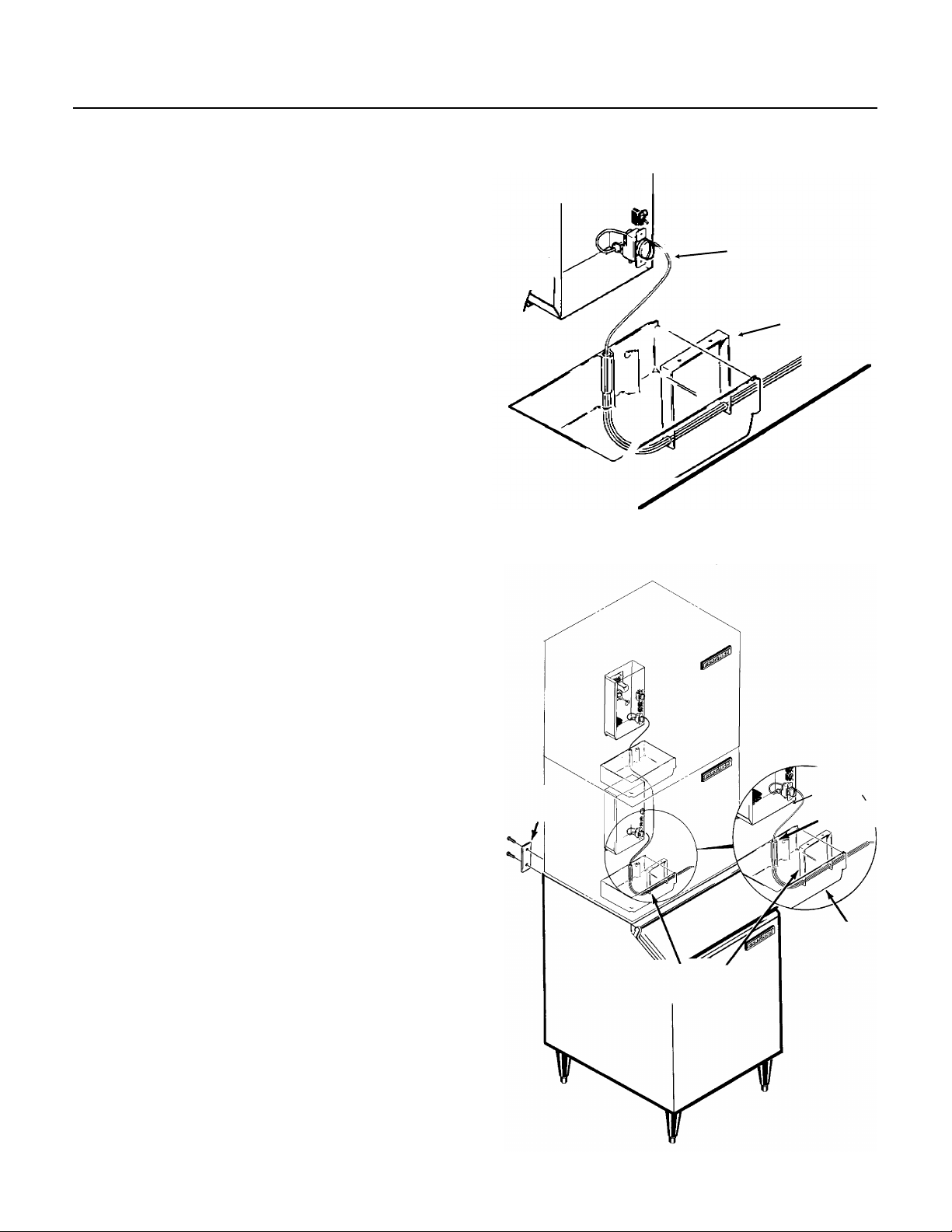
Bin Thermostat Installation:
1. Remove rubber cap from the end of the
thermostat bracket.
2. Attach the bin thermostat bracket to the bottom
of the ice machine using the thumb screws
provided. There are pre-drilled and tapped holes
located just behind the cube drop area. The end of
the bin thermostat bracket with the plastic tubing
on it will fit into the hole in the base of the machine.
3. Locate and uncoil a portion of the bin thermostat
capillary tube. Route the end of the capillary tube
into and through the bin thermostat bracket tube. It
should be inserted the full length of the tube, but
not past the end.
Thermostat
Capillary Tube
Bin Thermostat
Bracket
Stacking
Stacking:
This machine will stack onto any CM250,
CME250, CM450, CM500, CME500, CM650 or
CME650 with the same cabinet depth (24").
Note: Stacking requires two remote condensers.
1. Remove and discard the top panel from the
lower unit.
2. Carefully lift the uncrated top unit onto the
bottom unit. Use of a mechanical lift is
recommended for this step.
3. Align the two ice maker cabinets.
4. Secure the top unit to the bottom one with the
hardware and straps shipped with the upper
machine.
5. Locate and uncoil all of the bin thermostat
capillary tube.
6. Route the bin thermostat capillary tube from the
upper unit, through the hole in the back of the
reservoir, through the lower unit and into the bin
thermostat bracket. Discard upper unit bracket.
March 1994
Page 4
Strap
Bin Thermostat Bracket
Capillary Tube
Routing Hole
Page 5
FOR THE INSTALLER: Remote Condenser
CME500R
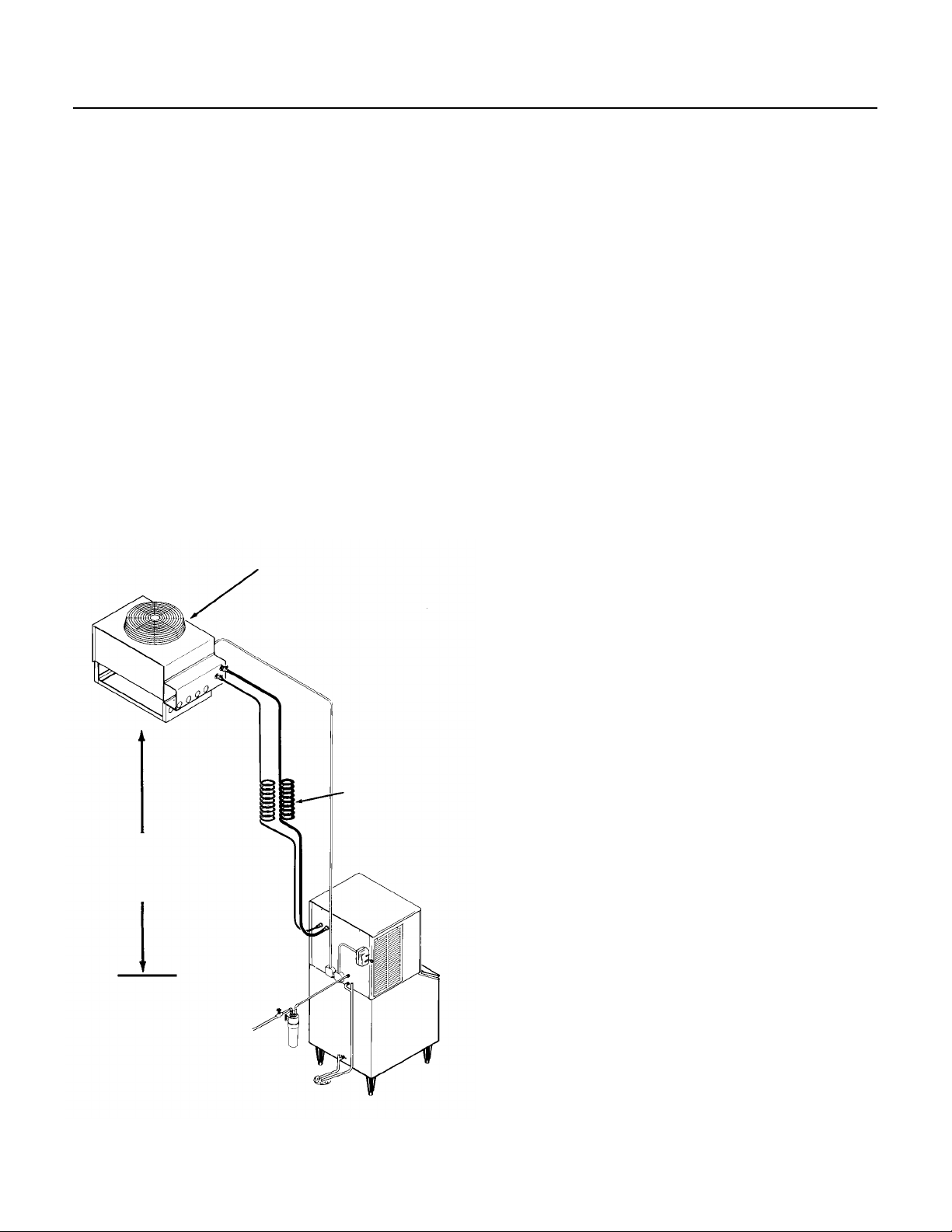
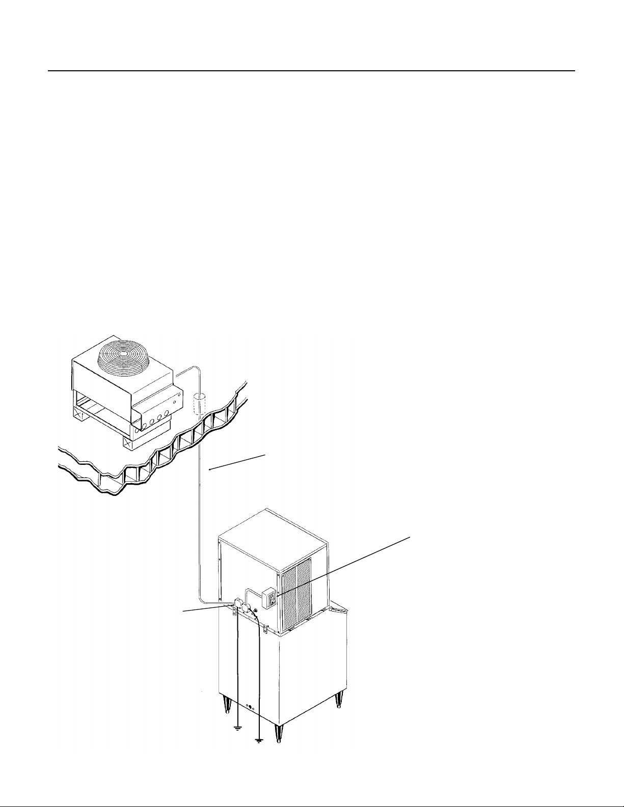
Locate the condenser as near as possible to
the interior location of the ice maker.
Location of the condenser is limited by the specific
length of precharged refrigerant tubing supplied for
the application. The pre-charged tubing connects
the icemaker to the remote condenser. The
condenser must be above the ice maker.
Select the best available location, protecting the
condenser from extremes of dirt, dust, and sun.
Meet all applicable building codes.
Roof Attachment:
Install and attach the remote condenser unit to the
roof of the building, using the methods and
practices of construction that conform to the local
building codes, including having a roofing
contractor secure the condenser to the roof.
Remote
Condenser
Precharged Line Routing
///////////////////////////////CAUTION/////////////////////////////////
Do not connect precharged tubing until all routing
and forming of the tubing is complete. See the
coupling instructions for connecting instructions.
////////////////////////////////////////////////////////////////////////////////
1. Each set of precharged refrigerant lines consists
of a 3/8 inch diameter liquid line, and a 1/2 inch
diameter discharge line. Both ends of each line
have quick connect couplings, the end without
access valves goes to the icemaker.
Note: The openings in the building ceiling or wall,
listed in the next step, are the minimum sizes
recommended for passing the refrigerant lines
through.
2. Have the roofing contractor cut a minimum hole
for the refrigerant lines of 1.75". Check local
codes, a separate hole may be required for the
electrical power to the condenser.
///////////////////////////////CAUTION//////////////////////////////////
DO NOT KINK OR CRIMP REFRIGERANT
TUBING WHEN INSTALLING IT.
////////////////////////////////////////////////////////////////////////////////
Locate Condenser No
Lower Than Ice Machine
TYPICAL
INSTALLATION
Excess
Tubing
Inside
Building
3. Route the refrigerant lines through the roof
opening.
Follow straight line routing whenever possible.
Any excess tubing MUST be retained within the
building.
4. Spiral any excess length of pre charged tubing
inside the building. Use a horizontal spiral (as
illustrated) to avoid any traps in the lines.
Note: Spiral need not be as tight as illustrated.
5. Have the roofing contractor seal the holes in the
roof per local codes.
October 1994
Page 5
Page 6
Discharge Line
Insulation
CME500R
FOR THE INSTALLER: Coupling Instructions
////////////////////////////////CAUTION/////////////////////////////////
The couplings on the sets of precharged lines are
self sealing when installed properly. Carefully
follow the instructions:
////////////////////////////////////////////////////////////////////////////////
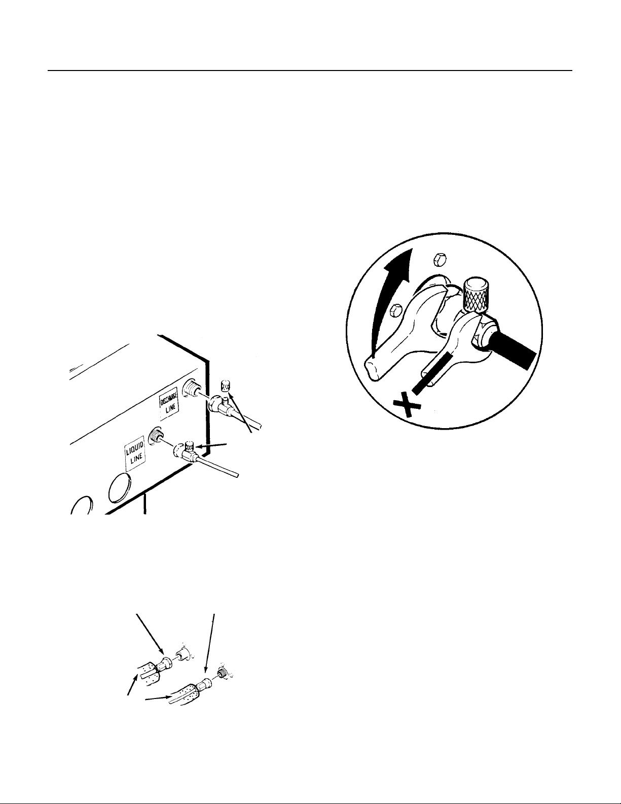
Initial Connections:
1. Remove the protector caps and plugs. Wipe the
seats and threaded surfaces with a clean cloth to
be certain that no foreign matter remains on them.
2. Lubricate the inside of the couplings, especially
the O-Rings with refrigerant oil.
••The 1/2 inch discharge line (schrader valve
end) goes to the remote condenser fitting
marked “discharge line”.
••The 3/8 inch liquid line (schrader valve end)
goes to the remote condenser fitting marked
“liquid line”.
Final Connections:
3. Begin tightening the couplings together by
hand, then using two wrenches (it is important that
ONLY the nut on the precharged lines be turned,
the other parts of the couplings must NOT be
allowed to turn or the process will tear out the
diaphragms and they will be loose in the
refrigeration system) tighten the coupling until it
bottoms out or a definite increase in resistance is
felt.
TIGHTENING THE QUICK CONNECTS
Schrader
Valves
••The 1/2 inch discharge line goes to the
icemaker fitting marked “discharge line”.
••The 3/8 inch liquid line goes to the icemaker
fitting marked “liquid line.”
Liquid Line
Ice Maker Connections
4. Using a marker or pen, mark a line lengthwise
from the coupling union nut to the bulkhead. Then
tighten the coupling and additional 1/4 turn. As the
nut turns, the line will show when 1/4 turn is made.
5. After all connections are made, and after the
king valve has been opened, check the couplings
for leaks.
Note: The system charge is contained in the
receiver tank of the ice machine. Only "holding"
charges are present in the "precharged" tubing or
the condenser.
March 1994
Page 6
Page 7
FOR THE ELECTRICIAN
HAND
DISCONNECT
SWITCH
CME500R
SEE NAMEPLATE for current requirements to
determine wire size to be used for electrical
hookup. When the cuber and the remote
condenser are connected, each must be grounded
to the other using the ground screws provided in
the respective junction boxes. The cuber then
requires a solid chassis to chassis earth ground
wire. See Wiring Diagram.
Be certain the cuber is connected to its own
electrical circuit and individually fused. Voltage
variation should not exceed ten percent of the
nameplate rating, even under starting conditions.
Low voltages can cause erratic operation and may
be responsible for serious damage to the
icemaker.
ELECTRICAL CONNECTIONS
The remote condenser is designed to be powered
from the ice machine. There is a separate
electrical junction box at the back of the ice maker
for the remote condenser. Wire the remote
condenser to the ice maker in accordance with
local and national electric codes. All outdoor wiring
must be in rain proof conduit.
The condenser fan motor will run whenever the
compressor is running.
Electrical connections are made at the rear of
the icemaker, inside the junction box.
All external wiring should conform to the
national, state and local electrical code
requirements. Usually an electrical permit and
services of a licensed electrician will be
required.
REMOTE CONNECTION
INTERCONNECTING
WIRES
October 1994
Page 7
Page 8
3/8" Male
Flare
CME500R
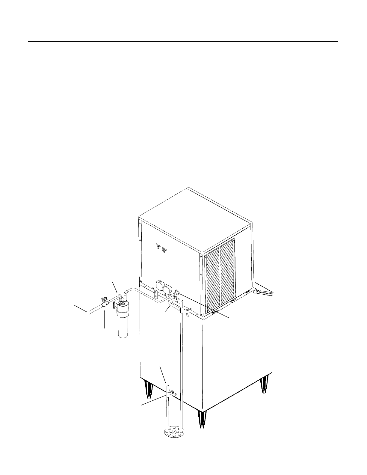
FOR THE PLUMBER
The recommended water supply line is a 3/8-inch
O.D. copper tubing with a minimum operating
pressure of 20 PSIG and a maximum of 80 PSIG.
Connect to cold water supply line with standard
plumbing fittings, with shut off valve installed in an
accessible place between the water supply and
the cuber. In some cases a plumber will be
required.
Water Limitations:
An ice machine is a food manufacturing plant, it
takes in a raw material, water, and turns it into a
food product, ice. The purity of the water is very
important in obtaining pure ice and in maximizing
product life. Even though there isn’t one filter that
will cure all water problems, a good filter combined
with a polyphosphate feeder gives about the best
overall performance.
DRAIN
Connections: All drains are gravity type and must
have a minimum of 1/4-inch fall per foot on
horizontal runs. The drains to be installed to
conform with the local plumbing code. Install a
vertical open vent on drain line high point to insure
good draining. The ideal drain receptacle is a
trapped and vented floor drain. Recommended bin
drain is 5/8 inch O.D. copper tubing and should be
vented and run separately. Insulation for high
humidity areas is recommended.
The ice machine sump drain is 3/4" FPT. There
must be a vent at this connection for proper sump
draining.
Potable
Water
Supply
Hand Shut
Off Valve
Maintain The Code
Required Air Gap
Between Drain Lines
And Building Drain
Optional
Filter
BIN DRAIN
Note: Some
Bins Drain Out
The Bottom
Sump Drain Must
Be Vented
3/4" FPT
Vent
WATER SUPPLY AND DRAIN CONNECTION
March 1994
Page 8
Page 9
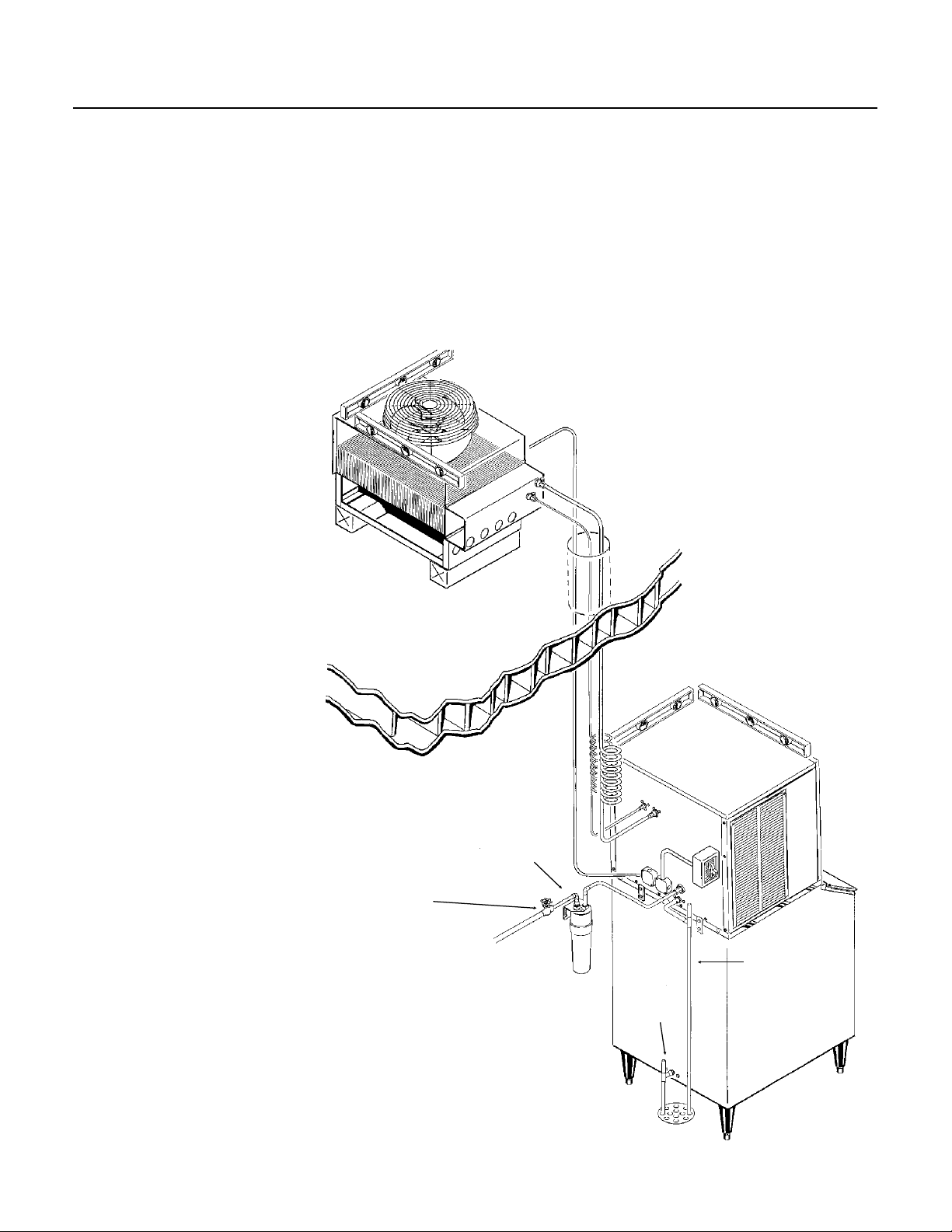
FINAL CHECK LIST
1. Is the cabinet in a room where ambient
temperatures are within the minimum and
maximum temperatures specified?
2. Is there clearance at the left and back sides of
the cabinet for service access?
3. Has water supply pressure been checked to
insure a minimum of 20 PSIG and a maximum of
80 PSIG operating pressure?
4. Is the cabinet level?
5. Check that any shipping material has been
removed from inside the
cabinet.
6. Check that the bin
thermostat bracket has been
installed, and the bin
thermostat capillary tube has
been routed thru the bracket.
7. Have all electrical, water and
drain connections been made?
CME500R
FINAL INSTALLATION
LEVEL
ASSEMBLY
8. Is the water supply line shut
off valve installed and electrical
wiring properly connected?
9. Check all refrigerant lines
and conduit lines, to guard
against vibration or rubbing and
possible failure.
10. Have the bin and cabinet
been wiped clean?
11. Has the Manufacturers
Registration form been properly
filled out? Check for correct
model and serial numbers from
Serial nameplate, then mail to
the SCOTSMAN factory.
12. Has the owner/user been
given the Service Manual and
instructed how to operate and
maintain the icemaker?
13. Has the owner been given
the name and telephone
number of the authorized
SCOTSMAN Service Agency
serving him?
PRECHARGED
LINES
CONNECTED
OPTIONAL
FILTER
HAND SHUT
OFF VALVE
SUMP
DRAIN
BIN
DRAIN
October 1994
Page 9
Page 10

Overflow
Standpipe
CME500R
COMPONENT LOCATION
The ice machine is designed for front service.
Many components are serviceable from the front
without removing the side panels:
Behind the front panel:
••Water pump
••Inlet water valve
••Reservoir
••Evaporators
••Water distributor
••Control box with cube size control adjustment
••ON/OFF switch
••Compressor switch
Inside the control box is the control system for the
ice machine.
Timer
Cube Size Control
Control Box
Bin Thermostat
Master Switch
Compressor Switch
Bin Thermostat
Water
Distributors
Drain Trough
Water Pump
Component Location
Bin Thermostat Bracket
Water Inlet Valve
March 1994
Page 10
Page 11

COMPONENT DESCRIPTION: Control System
CME500R
Cube Size Control
This reverse acting thermostat controls the length
of the freezing cycle. It is sensing the temperature
of the suction line. When the suction line gets cold
enough, the cube size control closes (on
temperature fall) and starts the timer. A change in
either ambient air or incoming water temperature
will affect the efficiency of the refrigeration system,
and this will vary the length of time it takes the
evaporator to reach the temperature at which the
cube size control is preset to close. See CUBE
SIZE ADJUSTMENT BEFORE attempting to adjust
the control.
Relay
The multi-function, three pole, double throw,
plug-in relay is installed directly into a receptacle
on the printed circuit board in the control box. The
relay functions in part to by-pass the bin
thermostat control to prevent the icemaker from
shutting OFF, when the bin thermostat opens
during the freezing cycle. The bypass action
serves to ensure full-sized ice cubes with each
harvest cycle.
Timer - Timer & Switch Assembly
The function of the timer begins when activated by
the cube size control. The outer surface, or large
diameter lobe of the timer cam, determines the
timer cycle for finish freezing of the ice cubes,
while the inner surface, or small diameter lobe,
determines the time cycle for the harvest cycle.
When the microswitch button is pushed in there is
power connected to the coil of the relay, and the
unit is in the freeze cycle. When the microswitch
button is released, the power to the relay is
stopped, and the unit goes into harvest. The
microswitch is actuated by a cam assembly
directly connected to the timer motor.
One complete rotation of the cam will take eight
minutes. Harvest is preset at two and 2 thirds
minutes, but is adjustable.
High Pressure Safety Cut Out Switch
This is a manual reset control that shuts down the
icemaker, should the discharge pressure ever
reach 450 PSIG. Located next to the control box.
Low Pressure Control (Pump Down)
Relay
CONTROL BOX
This pressure control connects power to the
compressor contactor coil. Its Cut In is 30 PSIG
and its Cut Out is 15 PSIG. Located behind the
control box.
High Pressure Safety
Cut Out Switch
Cube Size Control
Timer & Switch
October 1994
Page 11
Bin Thermostat
Page 12

CME500R
COMPONENT DESCRIPTION: Water System
Water Inlet Solenoid Valve
The water inlet solenoid valve controls the flow of
water to the reservoir. It fills the reservoir with
water and excess water overflows out the
standpipe and down the drain. This action fills and
rinses the reservoir during each harvest cycle. The
flow rate is .75 g.p.m.
Water Pump
The water pump operates whenever the ice
machine is making ice. It picks up water from the
reservoir and forces it to the top of the evaporator,
where it enters the water distribution system.
Water Distribution System
The water distribution system evenly supplies
water to all cells of the evaporator plates. The
water pump pumps water from the sump up the
vertical tygon tube to the tee.
From there water is channeled through the water
manifold to the water distributors, above each
evaporator plate, and from six holes within each
distributor, water flows to the cells of each side of
the evaporator plates. Gravity flow returns the
unfrozen excess portion of water to the sump
reservoir for recirculation.
Water Distribution
System
Water
Pump
Water System Components
Water Inlet
Valve
March 1994
Page 12
Page 13

INITIAL STA RT UP
Timer
Bin
Thermostat
MICROSWITCH
FREEZE
PORTION
Before Start Up:
1. Check that the Master ON-OFF switch and the
Compressor ON-O FF switch are in the OFF
position.
CME500R
FRONT VIEW OF TIMER
ACTUATOR
BUTTON
2. Switch o n the electrical power. Electrical power
must be supplied to the ice machin e for 4 hours
before start ing the compre sso r for th e firs t time .
The crankcase heater will now warm up the
compressor’s oil. The oil is warmed to evaporate
any refrige ran t that may hav e colle ct ed in it. If
there is refrigerant in the oil when the compressor
starts, the oil will f oam and will not lubrica te the
compressor properly, shorte ning its life.
Do not start the compressor for the first time
unless the dome of the compressor is warm.
Start Up:
1. Remove front panel by removing screws at the
base and pulling out.
2. Remove two screws and the cont rol box cove r.
3. OPEN the water supply line shut off valve.
4. Open the “king” valve on the receiv er.
5. Inside the control box is the shaft of the timer
and the switch assembly. Rotate the shaft of the
timer and switch assembly clockwise to start the
timer. The timer starts when the act uator arm on
the microswitch drops of f ou ter cam in to cam slot .
See “Front View of Time r”.
CAM
HARVEST
PORTION
CONTROL BOX
6. Move the Master ON-OFF switch to the ON
position.
7. Allow the rese rvo ir t o fill. If need ed, ro ta te the
timer clockwise a to begin anot her "harve st" cycle
to add more water to the reservoir.
Note: Some water will drip off the evaporators, this
is normal and there will be a reduction in water
dripping after seve ral cyc les of ic e.
8. W hen the sump has fille d, move the co mpre sso r
ON-OFF toggle switch, to the ON position.
9. Check operation of the freezing cyc le: As the
icemaking pro cess be gin s; fe elin g the met al parts
of the evaporat or plate reveals cold tempera tu re,
very shortly ice begins to form. T u bing will become
frosted at the top of the evaporator plate. Freezing
time will ra nge between 15 and 18 minut es.
Longer time for temperatures above 70 degrees F.
and shorter time requ ired when temperatures are
below 70-degre es F.
Average co mple te cycle time
is about 18 minutes.
Cube Size
Control
Master Switch
Compressor
Switch
April 1995
Page 13
Page 14

CME500R
INITIAL START UP
10. Check Cube Size
To produce SMALLER sized ice cube:
Locate cube size control knob, in the front of the
control box. Rotate one eighth of a turn
COUNTER Clockwise. Observe size of the ice in
the next ice cube harvest and adjust in one eighth
turn or less increments, until correct ice cube is
achieved.
To produce LARGER ice cube:
Locate cube size control on the front of the control
box Rotate the adjusting knob one eighth of a turn
Clockwise. Observe size of ice cubes in the next
cube harvest and adjust in one eighth turn or less
increments, until correct ice cube size is achieved.
11. Check harvest time. The machine will have
to harvest all of the cubes before it goes back
into the freeze cycle.
Increase the Harvest Time if there is less than 15
seconds of harvest time after the last cube has
fallen into the bin.
CUBE SIZE DIAGRAM
JUST RIGHT
When the cubes are the correct size,
they will be connected together
vertically, and drop off in strips.
The batch weight per cycle should be
about 5.5 lb.
TOO SMALL
Decrease the Harvest Time if there is much more
than 15 seconds of harvest time after the last cube
has fallen into the bin. Note: Harvest time is
dependent upon the water and air temperatures at
the ice machine. Colder air and water will result in
faster ice making, but longer harvest cycles. Do
NOT adjust harvest time too short, as this will
cause a freeze up of the evaporators.
CONTROL BOX
CUBE SIZE
CONTROL
To Adjust Harvest Time:
A. Disconnect electrical power.
B. Locate timer cam in the control box.
C. Loosen set screw holding the two halves of the
cam together, and rotate the front half to increase
or decrease the harvest portion of the cam (low
part).
D. Re-tighten the set screw.
E. Reconnect power and check the cube size after
the next cycle (cube size may need adjustment).
12. Replace control box cover and all cabinet
panels and screws.
13. Check operation of the bin control by holding
ice on the bin control tube in the bin. The machine
should shut off at the end of the harvest cycle.
14. Thoroughly explain to the owner/user the
significant specifications of the icemaker, the start
up and operation, going through the procedures in
the cleaning instructions. Answer all questions
about the icemaker by the owner; and inform the
owner of the name and telephone number of the
local authorized SCOTSMAN Distributor, or
service agency.
BIN ICE LEVEL
SWITCH
March 1994
Page 14
Page 15

FREEZING CYCLE OPERATION
Hot Gas
Valve
(Closed)
CME500R
Water from the sump assembly is pumped to the
water distributor system at the top of each
evaporator plate. From the water distributor the
water cascades by gravity over all cells of the plate
and to the sump assembly below.
At the beginning of the freezing cycle, the electrical
circuit is completed to the compressor and the
water pump. The water pump operates
continuously, through both the freezing cycle and
the harvest cycle.
During the freezing cycle, the hot gas solenoid
valve is CLOSED and the water inlet solenoid
valve is CLOSED. When the ice cubes are partially
formed, the cube size control will sense the
temperature at which it is preset to CLOSE. This
will complete the electrical circuit to the timer. The
timer then controls the remainder of the freezing
cycle.
The timer will keep the icemaker operating in the
freezing cycle for a selected length of time. This
will give the ice cubes time to fully form. After that
selected length of time, the timer will switch the
icemaker into the harvest cycle, through the
contacts of the timer assembly microswitch.
Low Temperature Freeze:
When the outside air temperature is low, the Head
Pressure Regulator will close off the liquid line to
the receiver, causing liquid refrigerant to back up
into the condenser until the head pressure builds
up to 240 PSIG. While this is occurring, the head
pressure regulator passes discharge gas into the
receiver to keep the refrigerant flowing.
Pressure
Control
Receiver
Liquid
Line
Head
Valve
King
Valve
Discharge
Line
Discharge
Compressor
Crankcase
Heater
Fan
Motor
Coil
Filter/Dryer
Heat
Exchange
Liquid
Line Valve
Water
Valve
(Closed)
REFRIGERATION SCHEMATIC
Filter
Suction
Line
TXV
Evaporators
Pump
Drain
October 1994
Page 15
Page 16

Hot Gas
Valve
(Open)
CME500R
HARVEST CYCLE - HOT GAS BYPASS
When the timer switches the icemaker into the
harvest cycle, high pressure, high temperature
refrigerant gas discharged from the compressor
flows through the hot gas solenoid valve into each
evaporator plate. During this cycle, the refrigerant
bypasses the condenser. In the electrical circuit,
both the compressor and the water pump are
operating and the hot gas solenoid valve is
energized and OPEN and the water inlet solenoid
valve is OPEN.
The finished ice cubes are released from the sides
of each evaporator plate by the warming effect of
the hot gas condensing in each evaporator plate
and the water cascading over the ice cubes. The
released ice cubes drop into the ice storage bin
below. At the end of the harvest cycle, the timer
cam will push the actuator arm to the microswitch
IN. If the ice level control is still CLOSED, a whole
new cycle will begin. If the ice level control is
OPEN, the icemaker will begin to shut OFF.
Pump Down Cycle:
When the ice level control is open at the end of the
harvest cycle, power is removed from the liquid
line valve coil, and the pump down cycle begins.
The compressor will continue to run until the pump
down control, sensing low side pressure, opens at
15 PSIG.
Pressure
Control
Receiver
Liquid
Line
Head
Valve
King
Valve
Discharge
Line
Discharge
Compressor
Crankcase
Heater
Fan
Motor
Coil
Filter/Dryer
Heat
Exchange
Liquid
Line Valve
Water
Valve
(Open)
REFRIGERATION SCHEMATIC
Filter
Suction
Line
TXV
Evaporators
Pump
Drain
March 1994
Page 16
Page 17

CLEANING & SANITIZING
1. Remove front panel.
2. Remove control box cover, and turn the timer
cam clockwise until the unit is in a harvest cycle. At
the end of the harvest cycle switch the master and
compressor switches to OFF. Replace the control
box cover.
Electrical Shock
Hazard.
Electrical shock can
cause personal injury.
Cleaning procedures are
done with the power ON.
3. Remove all ice from the bin.
4. Remove 4 thumbscrews and the evaporator
cover.
5. Remove water pump discharge hose from
evaporator water inlet, direct hose into bin or
bucket and switch the master switch ON until
reservoir is empty of water. Replace hose on inlet.
6. Replace evaporator cover.
7. Mix 8 ounces of Scotsman Ice Machine Cleaner
with 1 gallon of warm (95
pour into the reservoir until full.
8. Switch the master switch ON, and operate the
unit for 20 minutes, then switch the unit OFF.
9 Repeat steps 4 and 5.
10. Wash the plastic and stainless liners of the
freezer section with a solution of household bleach
(1 ounce of bleach to 2 gallons of water) and warm
o
(95
F. - 115oF.) water. Allow to air dry.
0
F. - 1150F.) water and
Scotsman Ice Machine
Cleaner contains
acids. These
compounds may cause
burns.
If swallowed, DO NOT
induce vomiting. Give
large amounts of water
or milk. Call Physician
immediately. In case of
external contact, flush
with water.
KEEP OUT OF THE
REACH OF CHILDREN.
CME500R
11. Pour
into the reservoir. Replace the evaporator cover.
12. Switch the master switch back ON, operate the
unit for 5 minutes. Switch unit OFF.
13. Repeat steps 4, 5 and 6.
14. Pour about 1/2 gallon of clean potable water
into the reservoir, and switch the master switch
ON. After 5 minutes switch the master switch OFF
and repeat steps 4, 5 and 6.
15. Switch master and compressor switches ON.
16. Replace the front panel
17. Discard the next batch of cubes to make sure
all of the acid & sanitizer is gone.
/////////////////////////////////CAUTION///////////////////////////////
DO NOT use ice cubes produced from the
cleaning or sanitizing solutions. Be sure none
remain in the bin.
/////////////////////////////////////////////////////////////////////////////////
18. Pour hot water into the storage bin to melt the
cubes and also clean out the bin drain.
19. Wash the bin liner with a solution of household
bleach (1 ounce of bleach to 2 gallons of water)
and warm (95
20. The unit will now continue automatic operation.
Water Distributor:
Note: The water distributor may need to be
cleaned separately.
1. Remove evaporator cover.
2. Remove water distributor assembly by pushing
the assembly to the right until the left end clears
the retaining tab.
3. Lift up the left end of the water distributor
assembly and pull the assembly to the left.
4. Un-snap the water distributors from the "T", and
inspect for mineral deposits. Clean as required.
5. Reverse above steps to reassemble. Be certain
that water distributors are in place and secure.
Scale that may form on the plastic liner can be
removed by scrubbing the surface with a mixture
of Scotsman Ice Machine Cleaner and hot water.
Remove any scale prior to cleaning.
1
⁄2 gallon of the solution mixed in step 10
o
F. - 115oF.)water. Allow to air dry.
October 1994
Page 17
Page 18

CME500R
CLEANING
Remote Condenser
1. Shut off the ice machine.
The fan blade can cause
personal injury.
Disconnect power
before beginning to
clean condenser.
2. Remove dirt and debris that might be under the
condenser.
3. Brush off the bottom of the condenser fins. Do
not use a wire brush.
4. Check to see that the inside of the condenser is
clean; light should be visible through the fins. If
not, clean the internal parts by vacuum, pressure
washer and/or coil cleaner.
Ice Storage Bin
The interior liner of the bin is in contact with a food
grade product: ice. The storage bin must be
cleaned regularly to maintain a sanitary
environment. Scale that may form on the plastic
liner of a bin may be removed by scrubbing the
surface of the line with a mixture of Scotsman Ice
Machine Cleaner and hot water. Remove any
scale prior to sanitizing.
Note: Some ice storage bins have Stainless
Steel liners. They may become stained from
chlorine gases released from the water. These
stains must be removed by regular cleaning to
prevent pitting of the metal liner. To prevent the
staining, an activated charcoal filter should be
added to the ice machines incoming water
supply line; activated charcoal removes the
chlorine. This may require more frequent
sanitation.
To remove scale:
1. Mix a cleaning solution of 4 ounces of Scotsman
Ice Machine Cleaner to 4 pints of hot (95
0
110
F.) water.
Scotsman Ice Machine
Cleaner contains
acids. These
compounds may cause
burns.
If swallowed, DO NOT
induce vomiting. Give
large amounts of water
or milk. Call Physician
immediately. In case of
external contact, flush
with water.
KEEP OUT OF THE
REACH OF CHILDREN.
2. Remove all ice from the bin.
3. Using rubber gloves, dip a nylon scouring pad
into the cleaning solution, and scrub the scale off
of the liner.
4. After the scale has been removed, rinse all of
the surfaces inside the bin with clean, potable
water.
To sanitize the bin and ice machine:
Follow local codes for frequency of sanitizing. Use
an approved sanitizer and follow the directions and
warnings of that sanitizer or use the following
instructions for use of household bleach, if it meets
local codes:
1. Remove all ice from the bin.
2. Mix a sanitizing solution of 1 ounce of
household bleach to 2 gallons of water.
0
F. to
3. Using clean rubber gloves and a clean cloth,
wipe all interior surfaces of the ice machine and
ice storage bin with the sanitizing solution.
Immerse any small parts in the sanitizing solution
and wash the parts, flushing the solution
thoroughly in, over and through all parts and
surfaces of the parts being cleaned.
4. Allow to air dry.
March 1994
Page 18
Page 19

CME500R
SYSTEM SPECIFICATIONS
The following numbers can be used as a guideline. There will be some variation from unit to unit.
Typical Cycle Time
•• 18 minutes @ 0
•• 22 minutes @ 90
Typical Harvest Ice Weight
•• 5-6 lb.
Typical Low Side Pressure
•• 35 PSIG @ 0
•• 36 PSIG @ 90
Typical Freeze Cycle Discharge Pressure
•• 270 PSIG @ 90
Refrigerant Charge
•• 208 ounces of R-404A
Harvest Time
•• Preset at 2.66 minutes, may be adjusted to suit local conditions
o
F. condenser, 70oF. air and 55oF. water
o
F. condenser, 90oF. air and 70oF. water
o
F. condenser, 70oF. air and 50oF. water
o
F. condenser, 90oF. air and 70oF. water
o
F. condenser, 90oF. air and 70oF. water
Typical Suction Pressure in Harvest
•• 90 PSIG @ 70
•• 110 PSIG @ 90
Typical Discharge Pressure in Harvest
•• 200 PSIG @ 70
•• 240 PSIG @ 90
Typical Compressor Amp Draw
o
F. air and 50oF. water
o
F. air and 70oF. water.
o
F. air and 50oF. water
o
F. air and 70oF. water.
•• 10-13 freeze, 14-16 harvest
High Pressure Cut Out
•• Cuts out at 450 PSIG, manual reset
Pump Down Pressure Switch
•• Closes at 35 PSIG
•• Opens at 15 PSIG
Compressor
•• Copeland RS55C1E-PAA-213
Bin Thermostat
•• Adjustable: C.I. range between 38.5
Timer
•• 1 revolution takes 8 minutes
o
F., and 43.5oF.; C.O. range between 33.5oF.,and 38.5oF.
Cube Size Control
••
Cut In adjustable between 0oF. and +250F.
Thermostatic Expansion Valve
••Not adjustable
October 1994
Page 19
Page 20

CME500R
ADJUSTMENTS
Electrical power present
in the control box can
cause personal injury.
Disconnect power
before beginning to
adjust timer.
Adjustment Of The Timer & Switch Assembly
One complete revolution of the cam on the timer
takes eight minutes. The machine ships with the
harvest time set at 2
the length of the harvest cycle allow enough time
for all the ice cubes to fall from the evaporator. Too
short of a time will cause the evaporator to freeze
up and stop ejecting ice into the bin. Too much
time wastes icemaking capacity, energy and water.
Adjustment of the harvest cycle may require a
corresponding adjustment of the cube size control.
Rotating the shaft of the timer cam clockwise will
allow putting the machine into either the freezing
cycle or harvest cycle, as required in the cleaning
instructions.
2
⁄3 minutes. It is important that
To Adjust The Timer & Switch Assembly:
MICROSWITCH
The length of the harvest cycle can be changed by
loosening the set screw on the cam, and then
rotating the shaft so that the opening between the
cams change. More of an opening between the
cams = more harvest time.
CLOSE UP
VIEW OF TIMER
SWITCH
ACTUATOR
CAM
ADJUSTING TIMER
TIMER
CAM
March 1994
Page 20
Page 21

CME500R
SERVICE DIAGNOSIS: Water
SYMPTOM POSSIBLE CAUSE PROBABLE FIX
No ice is made Inlet water valve will not open or
is dirty
No water being pumped over
evaporators.
Water inlet valve leaks thru at
high rate
Cubes are not uniform in shape Water distributors are dirty Clean water system
Long Freeze Cycle Inlet water valve leaks through Replace inlet water valve
See electrical/adjustment See electrical/adjustment
Makes thick ice/freezes up Water inlet valve restricted Clean or replace valve
Low water pressure Check water filter or supply
Cubes too large Inlet water valve leaks through Replace inlet water valve
See electrical/adjustment See electrical/adjustment
Low Capacity Incoming water very warm Check water temperature to
Lack of water See unit runs out of water
Unit runs out of water Reservoir leaks Repair leak
Inlet water valve restricted Clean or replace valve
Short harvest cycle Adjust timer
Water pressure too low Check supply
Clean inlet screen, check coil,
replace valve if required
Check pump motor, replace pump
if motor will not run.
No water in reservoir, check inlet
water valve, check reservoir for
leak.
Replace inlet water valve
building
October 1994
Page 21
Page 22

CME500R
SERVICE DIAGNOSIS: Electrical and/or Adjustments
SYMPTOM POSSIBLE CAUSE PROBABLE FIX
Machine does not operate No power Reconnect power
High pressure control open Reset, check machine
High temperature cut out open Hot gas valve leaks thru, replace
P. C. Board Open Replace board
Master switch open Test/replace
Timer contacts open Replace timer
Bin thermostat holding machine
off
Makes thick ice/freezes up Harvest Cycle too short Adjust timer
Low water pressure Check water filter or supply
Hot gas valve defective Replace hot gas valve
Cubes too small Adjust cube size
Cube size control stuck open Replace cube size control
Runs, makes no ice Pump problem or water leak in
reservoir
Water inlet valve either lets in no
water or leaks through
Timer stuck Replace timer
Relay does not energize; unit
stuck in harvest
Long freeze cycle Water inlet valve leaks through Replace inlet water valve
Water temperature too high Advise user
Cubes too small Cube size set wrong Adjust cube size
Cubes size control stuck closed Replace cube size control
Cubes too large Water inlet valve leaks through Replace inlet water valve and
Compressor cycles on and off on
pump down control
Compressor will not run Low pressure control will not close Check pump down control for
Unit cycles on and off anytime in
any cycle
Low refrigerant charge Locate leak, repair, replace drier,
Liquid line valve or drier restricted Check and replace
TXV restricted Check and replace
Head pressure control valve not
working (low condensing temp.)
Contactor coil open Check/replace contactor
Compressor windings open Check replace compressor
Loose connection in PC board Replace PC board
Test thermostat, replace if
contacts stuck open.
Check inlet water valve screen
and flow control.
Check water system and pump
Replace inlet water valve
Replace relay
adjust cube size control
evacuate and weigh in nameplate
charge.
Check/replace head pressure
control valve
proper operation
March 1994
Page 22
Page 23

CME500R
SERVICE DIAGNOSIS: Refrigeration and/or Mechanical
SYMPTOM POSSIBLE CAUSE PROBABLE FIX
Poor harvest Hot gas valve does not open Check for power to the coil, check
for not opening, replace
Head pressure control valve does
not maintain enough head
pressure.
Unit cycles off during freeze or
harvest
Low capacity High head pressure, from dirty
Unit shuts off before bin is full Bin thermostat adjusted to open
Compressor cycles on and off Low pressure control opening and
Frost on compressor Some frost will not hurt Do nothing
Hi temperature switch opens and
closes
condenser, faulty fan motor
Non condensable gas in the
system
Extreme hot location Relocate the cabinet
Overcharge of refrigerant Evacuate and weigh in nameplate
Hot gas valve leaks thru At the end of the freeze cycle
Liquid and discharge lines are in
contact with each other
too soon.
closing
Compressor overheats TXV not letting enough refrigerant
TXV meters too much refrigerant Adjust or replace TXV
Replace head pressure control
valve.
Hot gas valve leaks thru, replace it
Clean condenser, repair fan
motor
Purge system, evacuate and
weigh in nameplate charge
charge
there should be frost on the
evaporator end of the hot gas
tubes, if not replace the hot gas
valve
Separate and insulate them
Rotate knob on the thermostat
clockwise to a colder setting.
Check low side pressure, liquid
line valve must open and low side
pressure raise over 35 PSIG
before pump down control will
close to run compressor
into evaporators, adjust or
replace TXV
Mechanical fault with compressor,
replace compressor
October 1994
Page 23
Page 24

CME500R
REMOVAL AND REPLACEMENT
Cube Size Control
To remove the cube size control:
Electrical Shock
Hazard.
Electrical shock can
cause personal injury.
Disconnect power
before beginning to
service components.
Water Distributor Tubes And Manifold Tubes
To remove the water distributor tube and manifold
tube:
1. Remove the front panel.
2. Slide the water distributor tube to the front about
1/8-inch along the top of the evaporator plate, until
the water distributor tube can be unsnapped from
the flexible notch and lifted upward.
3. Unsnap and disconnect water distributor tubes
WATER
DISTRIBUTOR
1. Remove front panel.
2. Remove cover from control box.
3. Trace capillary tube, from the cube size control
to the refrigerant suction line.
Tube Well On
Suction Line
Cube Size
Control Pig Tail
REPLACEMENT OF THE CUBE SIZE CONTROL
from the water manifold section. To replace the
water distributor tubes and manifold tubes, reverse
the removal procedure. BE SURE the notches in
the water manifold tubes properly engage the
alignment keys in the tee. BE SURE the water
distributor tube is securely fastened at the notch at
both sides of the evaporator plate. Check identical
attachment for the left water distributor tube and
notch; also, that the distributor/manifold
connections at the top center of each evaporator
plate is snug against the top of the plate.
4. Remove the coiled capillary tube bulb from the
tube well on the suction line.
5. Remove electrical leads from the cube size
control.
6. Remove screws and pull the capillary tube
through the notch in the back of the control box.
Remove the cube size control. To replace the cube
size control, reverse the removal procedure.
March 1994
Page 24
Page 25

REMOVAL AND REPLACEMENT
CME500R
Inlet Water Solenoid Valve Assembly
Electrical Shock
Hazard.
Electrical shock can
cause personal injury.
Disconnect power
before beginning to
service components.
Water Pump
1. Remove front panel.
2. Unplug water pump electrical connection.
3. Drain water reservoir.
4. Use corbin clamp pliers to loosen and slide
corbin clamps on hoses away from pump.
5. Remove screws retaining pump to bracket.
6. Pull pump out of ice machine.
7. Reverse to reassemble.
8. Replace front panel.
8. Reconnect electrical power.
To remove the inlet water solenoid valve assembly:
1. Shut OFF water supply to machine.
2. Loosen and remove outlet water line from the
inlet water solenoid valve assembly.
3. Remove screws and pull the water solenoid
INLET WATER
VALVE
REMOVAL OF THE
INLET WATER VALVE
Removal of The
Water Pump
valve out to gain access.
4. Pull electrical cord from solenoid coil terminals.
5. Remove inlet water fitting from the water
solenoid valve. To replace the inlet water valve
assembly, reverse the removal procedures.
6. Reverse to reassemble.
Inlet Water
Valve Screen,
May Be
Cleaned As
Needed
October 1994
Page 25
Page 26

SERVICE PORT
CME500R
REMOVAL AND REPLACEMENT
Thermostatic Expansion Valve
1. Before replacing this valve, be certain that the
valve is the cause of the problem, and cannot be
adjusted.
2. Remove the top, service and front panels.
3. Discharge and recover the refrigerant.
4. Locate the TXV bulb (on the suction line),
remove the clamps and bulb from the tube.
5. With the refrigeration system open, unsweat the
TXV from the tubing.
6. Place the new TXV in position.
7. Wrap the new TXV body with wet rags. Do not
get any moisture in the valve.
8. Carefully braze the valve to the tubing. Examine
the joints, if they look good proceed to the next
step, if not, re-do them.
9. Install a new dryer, and braze it in place also.
10. Reattach the TXV bulb to the suction line in the
same place as the old one.
11. Evacuate the system to 200 microns.
12. Weigh or measure the nameplate charge into
the receiver.
13. If the machine has been off on the breaker
there may be refrigerant trapped in the oil of the
compressor, so do not restart until the compressor
has been warmed by the crankcase heater for 12
hours. If the compressor was warm throughout the
replacement process, the ice machine may be
restarted without waiting to re-warm the
compressor.
Hot Gas or Liquid Line Valve.
1. Before replacing this valve, be certain that the
valve is the cause of the problem.
2. Remove the top, service and front panels.
3. Discharge and recover the refrigerant.
4. Unplug the coil of the valve.
5. With the refrigeration system open, unsweat the
valve from the tubing.
6. Place the new valve in position.
7. Wrap the new valve body with wet rags. Do not
get any moisture in the valve.
8. Carefully braze the valve to the tubing. Examine
the joints, if they look good proceed to the next
step, if not, re-do them.
9. Install a new dryer, and braze it in place also.
10. Plug the power cord back onto the coil.
11. Evacuate the system to 200 microns.
12. Weigh or measure the nameplate charge into
the receiver.
13. If the machine has been off on the breaker
there may be refrigerant trapped in the oil of the
compressor, so do not restart until the compressor
has been warmed by the crankcase heater for 12
hours. If the compressor was warm throughout the
replacement process, the ice machine may be
restarted without waiting to re-warm the
compressor.
Refrigerant:
NO liquid refrigerant may be put into this system
anywhere except the receiver. DO NOT use the
access valves at the front of the machine for
weighing in the charge: use the “king” or receiver
service valve. All liquid HP62 must be weighed
into the receiver through the “front seated”
receiver outlet service valve.
FRONT SEATED VALVE
March 1994
Page 26
Page 27

REFRIGERATION SERVICE: HP62 (R-404A)
CME500R
THIS ICE MACHINE USES HP62 REFRIGERANT
AND POLYOLESTER COMPRESSOR OIL
DO NOT USE MINERAL OIL IN THIS
REFRIGERATION SYSTEM.
••HP62 is a "Near Azeotrope", and therefore
liquid charging is required
¤ Weigh in as much of the charge (as liquid)
into the receiver as possible.
¤ Install a sight glass between the manifold and
the suction side hose. Carefully meter liquid
into the suction side, using the manifold valve
to "flash off" the liquid before it enters the ice
machine. Do this until the proper charge has
been weighed into the system.
••When the system is serviced, a special liquid
line dryer is required (see parts list).
••Polyolester oil absorbs water very easily, and
therefore when the system is opened for
service, it must be re-sealed as soon as
possible (15 minutes maximum).
••Special leak detection equipment is required to
locate small refrigerant leaks. Usually a leak
detector capable of detecting a Halogenated
refrigerant or HFC-134a will work. Check with
the leak detector manufacturer if in doubt.
••As with any other refrigerant, do NOT mix HP62
with pressurized air when leak testing.
Pressure-Temperature Chart for HP62
VAPOR VAPOR
TEMP. PRESSURE TEMP. PRESSURE
(DEG F) (PSIG) (DEG F) (PSIG)
-20 . . . . . . 17 70 . . . . . . . 146
-18 . . . . . . 18 72 . . . . . . . 150
-16 . . . . . . 20 74 . . . . . . . 155
-14 . . . . . . 21 76 . . . . . . . 161
-12 . . . . . . 23 78 . . . . . . . 166
-10 . . . . . . 24 80 . . . . . . . 171
-8 . . . . . . . 26 82 . . . . . . . 177
-6 . . . . . . . 28 84 . . . . . . . 182
-4 . . . . . . . 29 86 . . . . . . . 188
-2 . . . . . . . 31 88 . . . . . . . 194
0 . . . . . . . 33 90 . . . . . . . 200
2 . . . . . . . 35 92 . . . . . . . 206
4 . . . . . . . 37 94 . . . . . . . 212
6 . . . . . . . 39 96 . . . . . . . 219
8 . . . . . . . 41 98 . . . . . . . 225
10 . . . . . . . 43 100 . . . . . . 232
12 . . . . . . . 46 102 . . . . . . 239
14 . . . . . . . 48 104 . . . . . . 246
16 . . . . . . . 50 106 . . . . . . 253
18 . . . . . . . 53 108 . . . . . . 260
20 . . . . . . . 55 110 . . . . . . 268
22 . . . . . . . 58 112 . . . . . . 275
24 . . . . . . . 60 114 . . . . . . 283
26 . . . . . . . 63 116 . . . . . . 291
28 . . . . . . . 66 118 . . . . . . 299
30 . . . . . . . 69 120 . . . . . . 307
32 . . . . . . . 72 122 . . . . . . 316
34 . . . . . . . 75 124 . . . . . . 324
36 . . . . . . . 78 126 . . . . . . 333
38 . . . . . . . 81 128 . . . . . . 342
40 . . . . . . . 85 130 . . . . . . 351
42 . . . . . . . 88 132 . . . . . . 360
44 . . . . . . . 91 134 . . . . . . 370
46 . . . . . . . 95 136 . . . . . . 379
48 . . . . . . . 99 138 . . . . . . 389
50 . . . . . . . 102 140 . . . . . . 399
52 . . . . . . . 106 142 . . . . . . 409
54 . . . . . . . 110 144 . . . . . . 420
56 . . . . . . . 114 146 . . . . . . 430
58 . . . . . . . 118 148 . . . . . . 441
60 . . . . . . . 123 150 . . . . . . 452
62 . . . . . . . 127 152 . . . . . . 464
64 . . . . . . . 132 154 . . . . . . 475
66 . . . . . . . 136 156 . . . . . . 487
October 1994
Page 27
Page 28

CME500R
REFRIGERATION SERVICE
General Information:
Scotsman recommends that any work on the
refrigeration system only be done when it is certain
that the system needs repair. Use conservation
minded service procedures:
••Refrain from checking refrigeration
pressures without reason.
ways to determine the proper operation of a
Scotsman ice machine without using refrigerant
gauges. Visual inspection of the water system,
observation of the ice formation, amp draw,
voltage, and other techniques will lead to proper
diagnosis. Scotsman also recommends that, at
the time of initial start up, gauges not be used.
There are many
••If gauges must be used, do not always check
the high side pressure. If the condenser is clean
and seems to be operating correctly, it most
likely is. The low side pressure is much more
important on an ice machine than is the high
side.
••If gauges must be used, use very short hoses.
Minimal refrigerant discharged into the hoses
equals minimal refrigerant discharged into the
air.
••Refrigerant should not be added except as a
way to determine the proper operation of the
product. If the system was low on refrigerant,
there is a leak, and it must be found and
repaired.
••This system has a critical charge, it must be
recharged with the correct amount of refrigerant
as listed on the nameplate of the ice machine,
or performance will suffer.
••Anytime the refrigeration system has been
opened, the dryer should be replaced.
Only a HFC type dryer should be used.
Note:
••When brazing the tubing connections to
components such as the hot gas valve, the
component must be protected by heat sink
material.
Recover, reclaim or recycle refrigerant. The
method chosen is up to the service company.
There are various mechanical devices that may be
used to recycle refrigerant at the field level,
however, Scotsman requires that any refrigerant
placed into a Scotsman ice machine meet ARI
spec 700-88. Reclaim programs are available
through most refrigerant wholesalers.
Access Valves: To use the access valves:
Remove the cap from the stem, use a 3/16" allen
wrench to check that the valve is CLOSED. The
remove the core cap.
Close the valve and replace the caps when the
job is finished. The valve must be closed and
the caps must be on or the valve will leak.
Torque Stem Cap to
8-12 ft. lb.
Allen
Wrench
Torque Stem to
6-8 ft. lb.
Access Valves
Note: There are no valve
cores in this valve.
Torque
Core Cap to
7-12 ft. lb.
March 1994
Page 28
 Loading...