

NS-75
4
®
Evolution / Evolution-SR
ASSEMBLY INSTRUCTIONS
Ref. # Description Qty.
1. Frame 1
25. Handle Bar 1
27. Seat Slider Assembly with Saddle 1
AFront Stabilizer Bar with Wheels and Feet 1
B Rear Stabilizer Bar with Feet 1
Small Parts Box 1
67 Water Bottle Cage 2
Small Part Box Contents
42. Pedals with Toe Clips & Straps (Left & Right) 1 Pair
44. Pop Pin Assembly for Head Tube 1
39. 13mm Hex Bolt 4
50. Flat Washer 8
51. 13mm Lock Nut 4
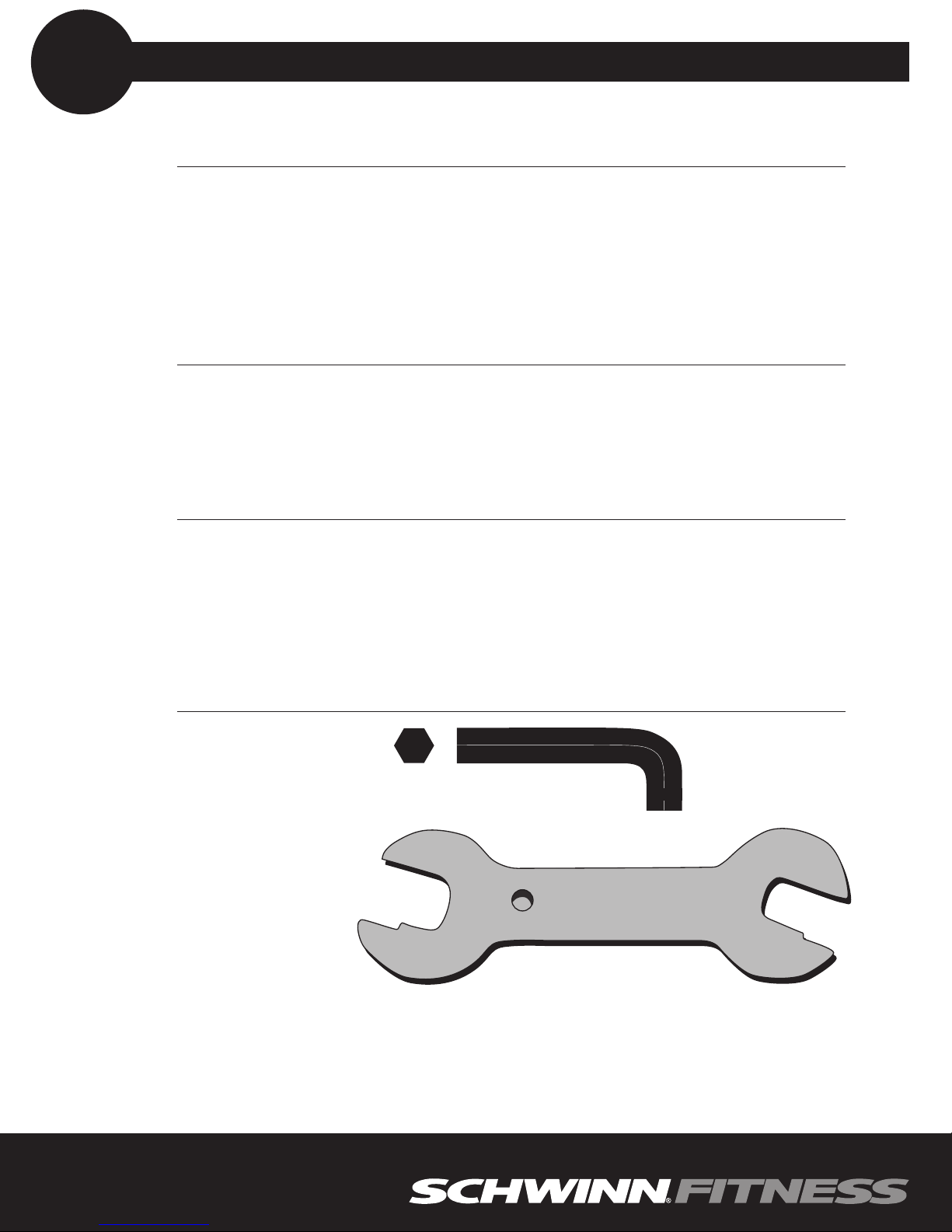
Tools Supplied
Stamped Steel 13/14/15/17mm Combination Wrench 1
5mm Hex Wrench 1
3mm Hex Wrench 1
Prior to assembly of the product, remove all components from the packaging and check them
against the packaged components list supplied above. Once you are certain that all the necessary
parts have been supplied, begin with the first assembly step.
Tools Needed
5mm Hex Wrench
3mm Hex Wrench
Adjustable wrench (not included)
SCHWINN EVOLUTION - PACKAGE COMPONENTS LIST
step
#1
2
Evolution / Evolution-SR
17/15
13/14
Stamped Steel
Combination wrench
NS-75
Ref. # Description Qty
1 Frame 1
AFront Stabilizer Bar with Wheels and Feet 1
B Rear Stabilizer Bar with Feet 1
39 13mm Hex Bolt 4
50 Flat Washer 8
51 13mm Lock Nut 4
Tools Required
Stamped Steel Combination Wrench 1
Adjustable wrench or 13mm Socket (not supplied) 1
5mm Hex Tool 1
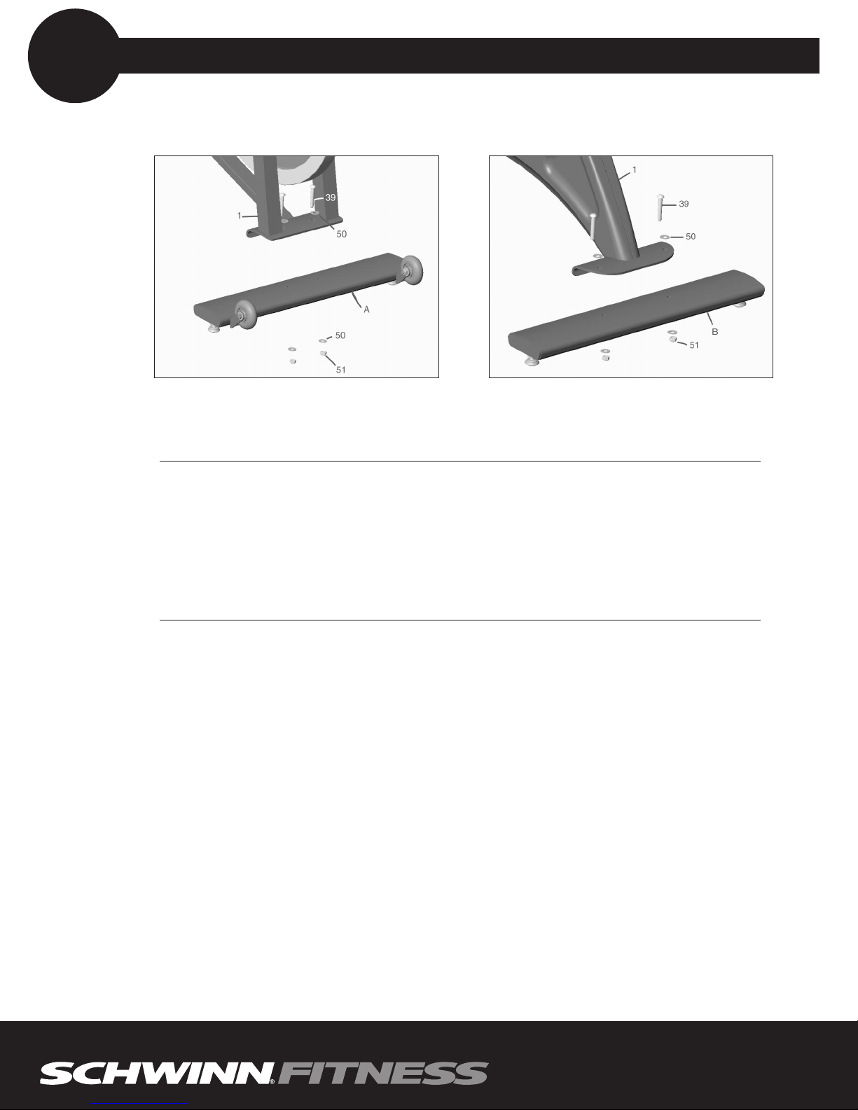
A. Position the Front Stabilizer Bar (A) under the frame bracket as shown in the illustration.
B. Make sure the adjustable feet are on the bottom and the transport wheels are facing up and
toward the front of the bike.
CAUTION:
IT IS VERY IMPORTANT TO APPLY GREASE TO THE 13mm HEX BOLT (39) PRIOR TO
MOUNTING THE 13mm LOCKNUT (51) THIS WILL ENSURE THAT YOU CAN REMOVE
THE NUT AT A LATER DATE.
C. Attach Front Stabilizer Bar (A) to Frame (1) using two hex bolts (39), four washers (50), and two
lock nuts (51). Tighten hardware firmly but do not over tighten as deformation of the stabilizer
tube may occur
D. At this time make sure that the adjustable feet with lock nuts are screwed fully into the stabilizer.
E. Position the Rear Stabilizer Bar (B) under the frame bracket as shown in the illustration.
F. Make sure the adjustable feet are on the bottom.
G. Attach Rear Stabilizer Bar (B) to Frame (1) using two hex bolts 39), four washers (50), and two
lock nuts (51). Tighten hardware firmly but do not over tighten as deformation of the stabilizer
tube may occur
H. At this time make sure that the adjustable feet with lock nuts are screwed fully into the stabilizer.
MATERIALS & TOOLS
step
#2
3
Evolution / Evolution-SR
Front
Rear
 Loading...