


Gas Hob Operating Instructions
Page 1 of 12
English
Contents
AU
Installation, 2-6
!
Positioning
!
Electrical Connection
!
Gas Connection
!
Data Plate
!
Burner & Injector Specification
!
!
Description of the Appliance, 7
!
Overall View
!
!
Start-up and Use, 8-9
!
Practical advise on using the burners
!
PP 30 TC 120 SF
Precautions and Tips, 10
General Safety
!
Disposal
!
!
Maintenance and Care, 11
!
Switching the appliance off
!
Cleaning the appliance
!
Gas tap maintenance
!
!
Troubleshooting, 12
!
!
!
!
!
!
!
!
!
!

Gas Hob Operating Instructions
Page 2 of 12
Installation
! Before operating your new appliance please read
this instruction booklet carefully. It contains
important information for safe use, installation and
care of the appliance.
! Please keep these operating instructions for
future reference. Pass them on to possible new
owners of the appliance.
Positioning
! Keep packaging material out of the reach of
children. It can become a choking or suffocation
hazard (see Precautions and tips)
! This appliance shall be installed only by
authorised personnel and in accordance with the
manufacturer’s installation instructions, local gas
fitting regulations, municipal building codes, water
supply regulations, electrical wiring regulations,
AS 5601/AG 601 - Gas Installations and any other
statutory regulations.
! Ventilation - Ventilation must be in accordance
with AS5601/AG 601 - Gas Installations. In
general, the appliance should have adequate
ventilation for complete combustion of gas, proper
flueing and to maintain temperature of immediate
surrounding within safe limits.
Positioning - The appliance can be fitted into a
working area as illustrated on the corresponding
figure. Apply the seal provided over the whole of
the area perimeter.
Combustible Surfaces - Any adjoining surface
situated within 200mm from the edge of any hob
burner must be a suitable non-combustable
material for a height of 150mm for the entire
length of the hob. Any combustible construction
above the hotplate must be at least 600mm above
the top of the burner and no construction shall be
within 450mm above the top of the burner. A
minimum depth of 60mm from the top of the
worktop surface must be provided for the
appliance.
Access to base - Where the base of the hotplate
can be accidentally touched, such as through a
cupboard or a pot drawer, a panel should be fixed
15mm below the base of the hotplate to prevent
accidental contact. The base of the hotplate is
very hot during operation.
Data Label - The Data Label is located on the
underside of the appliance. A duplicate label is
supplied to adhere in an accessible area adjacent
to the appliance. This appliance is suitable for
Natural and Propane Gas; ensure the available
gas supply matches the data label.
Gas connection - The Gas Connection is male
1/2” BSP and is situated 50mm from the right,
50mm from the rear of the hotplate and 25mm
below the top surface of the bench top.
There are two ways to carry out the connection to
the main gas line:
A. The hotplate can be connected with rigid
pipe as specified in AS5601 table 3.1.
B. The hotplate can be connected with a
Flexible Hose, which complies with
AS/NZS 1869 (AGA Approved), 10mm
ID, class B or D, no more than 1.2m long
and in accordance with AS5601
Ensure that the Hose does not contact the hot
surfaces of the hotplate, oven, dishwasher or
other appliance that may be installed underneath
or next to the hotplate.
The hose should not be subjected to abrasion,
kinking or permanent deformation and should be
able to be inspected along its entire length. Unions
compatible with the hose fittings must be used and
connections tested for gas leaks. The supply
connection point shall be accessible with the
appliance installed.
When the installation has been carried out, check
the perfect sealing of the entire connection
system, by using soapy solution.
Power Connection - Simply plug into a 3 pin
household socket outlet which is properly earthed.
Warning: In order to avoid hazard, any electrical
work performed on this equipment or its
associated wiring, should only be done by persons
authorised by the supplier or similarly qualified
persons.
The socket outlet for this hotplate shall be installed
near the hotplate and shall be easily accessible.
Gas Hob Operating Instructions
Page 3 of 12
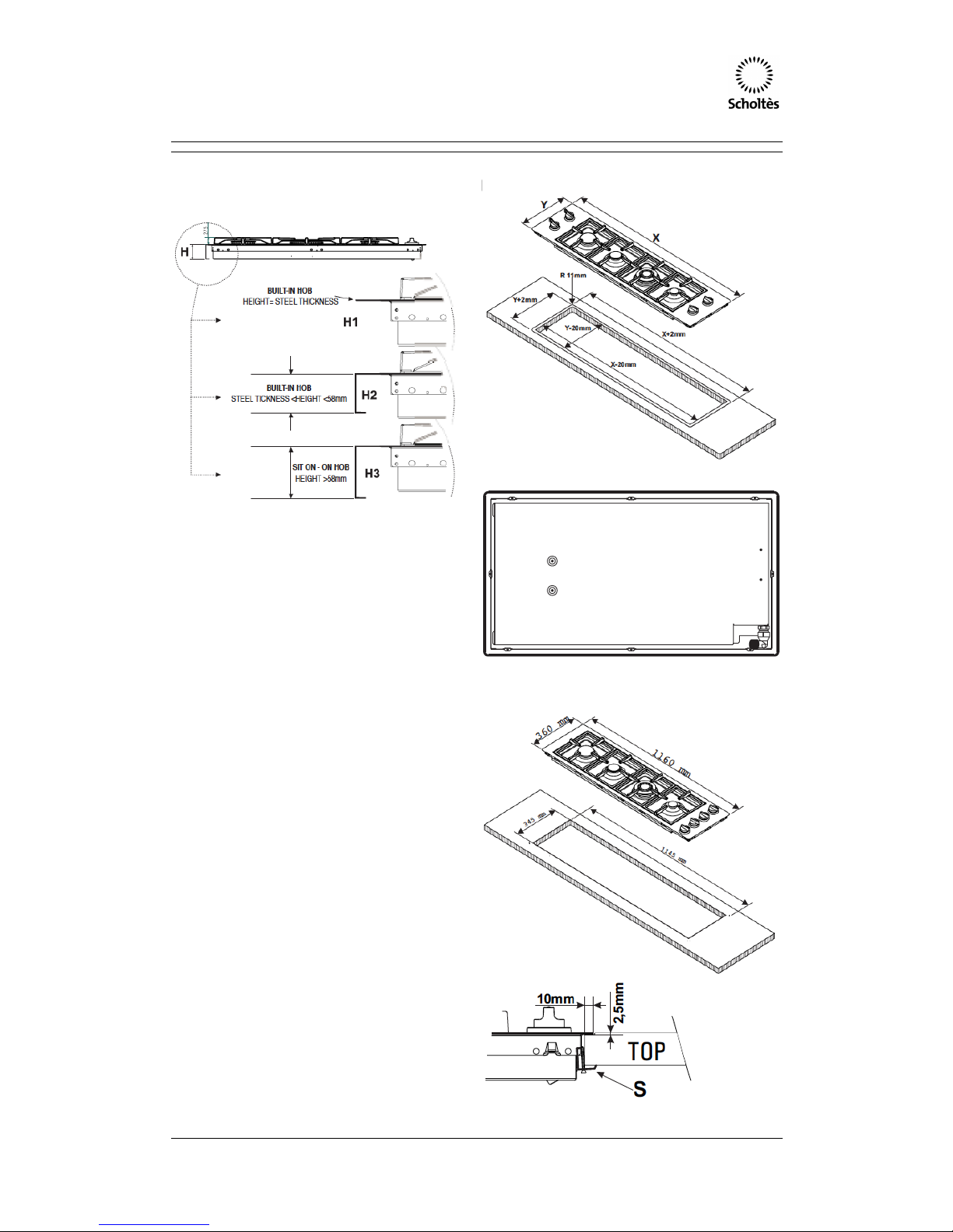
Securing the appliance to the cabinet
There are 3 different methods for installation of
the appliance:
fig.6
fig.5
fig.4
1. Built-in hobs flush with the worktop (see
figure 4, detail H1). In this case it is
necessary to make a hole with
measurements matching those of the
hob in the worktop. The measurement at
the side should be reduced by 2 cm so
as to ensure that 1 cm of the hob
overlaps with and rests on top of the
supporting surface (see figure 6).
To fit the hob flush with the worktop, it is
necessary to cut lower on this supporting
surface (see figure 5 and 6), so that both
the edge of the hob and the seal under it
can be positioned there.
Before fitting the hob to the worktop,
position the seal provided along the
perimeter of the hob, as illustrated in
figure 6. Brackets for fixing hobs to the
cabinet have been provided, and these
should be fitted as shown in detail S.
2. Built-in hobs with edges lower than 58
mm (see figure 4, detail H2). To install
this type of hob, a hole large enough to
accommodate the whole lower casing of
the appliance must be made on the
worktop intended to be under the hob.
Remember to leave a gap of at least 1
cm between the lower casing and the
worktop around the whole perimeter of
the appliance (the underside of the
casing can, however, touch the surface
below it). To fit the appliances, follow the
instructions given above in point 1 or use
any supplementary instruction leaflet that
is provided in special cases.
Gas Hob Operating Instructions
Page 4 of 12
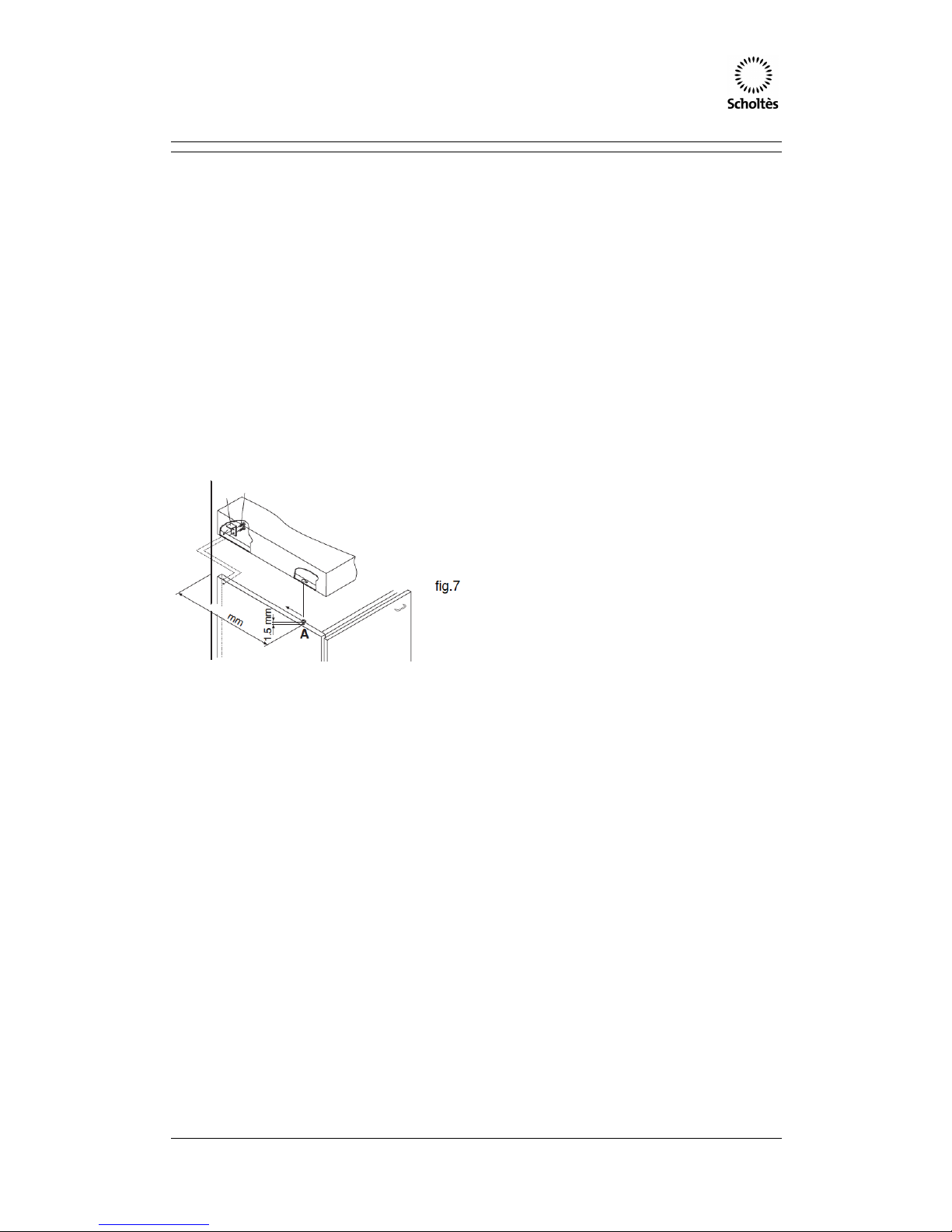
3. Sit-on hobs with edges higher than 58
mm (see figure 4, detail H3). In this case,
the lower casing of the hob does not
protrude further than the edge of the
appliance. Even when the hob is resting
on the worktop, it will suffice to leave
space for the gas supply tube and
electricity supply cable. To fit this type of
hob, follow the instructions below (fig. 7):
• Fix the two screws provided "A" at a
distance from the back panel as shown
in figure 7, leaving the heads of the
screws sticking out of the wood by 1.5
mm.
• Hook the hob onto the two screws "A"
and push it towards the back.
• Fix the appliance to the cabinet at the
rear, using the two brackets "B" and the
four screws "C" (these are all provided).
Electrical Connection
The hobs come equipped with a 3 pin plug and
power cable. The plug and power cable comply
with Australian requirements. Please check the
power rating, voltage and frequency indicated on
the data plate (located on the bottom of the hob as
well as on the front cover of this manual).
If the appliance is to be installed above an electric
built-in electric oven, the electrical connection to
the hob and oven must be carries out separately,
both for electrical safety purposes and to make it
easier to remove the oven.
The supply cable must not come into contact with
surfaces higher than 50°C.
! The installer must ensure the electrical
connection has been made and is compliant with
AS/NZS 3000 wiring rules.
Before connecting to the power supply, make sure
that:
• The appliance is earthed and the plug is
compliant with the law.
• The socket can withstand the maximum
power of the appliance, which is indicated
on the data plate.
• The voltage is in the range between the
values indicated on the data plate.
• The socket is compatible with the plug of
the appliance. If the socket is
incompatible with the plug, ask an
authorised technician to replace it. Do not
use extension cords or multiple sockets.
! Once the appliance has been installed, the power
supply cable and the electrical socket must be
easily accessible.
! The cable must not be bent or compressed.
! The cable must be checked regularly and
replaced by authorised technicians only (see
Assistance).
! The manufacturer declines any liability should
these safety measures not be observed.
N.B.: To allow for easy maintenance
procedures please ensure the area around the
hob are easily accessible after the hob has
been installed.
 Loading...