

Page 1

Remote Terminal Unit
W@de range
W310 (Brio)
Telemetry remote autonomous system
User's manual
W310
ade
w
Page 2

Page 3

W310 (Brio)
Contents
Safety information 4
Safety 4
Disclaimer 4
W310 security alert 4
Overview 6
Purpose 6
Main features 6
Self-sufficiency 7
Operating principles 7
Operating modes 8
Function indicator lights 8
Installation 9
Prerequisites 9
Internal view of W310 9
Inserting SIM card 9
Connectors 10
Commissioning 12
Preliminary checkings 12
Types of configuration 12
Wake up W310 and local activation of the dialogue 13
Activating a diagnostic SMS send 14
Local configuration of W310 (Kervisu) 16
Configuration using Kervisu 16
Configuration screen 17
Channels (1 to 8) screen 20
Counters screen 24
System screen 25
System error table 25
GSM screen 26
Modbus settings screen 27
Retrieval/Downloading of the configuration 28
Remote configuration of W310 (Kerweb) 29
Configuring the Supervisor (Kerwin) 30
Self-configuration: case of a W310 unit site 30
Manual creation of a W310 unit site 30
Testing the installation 31
Frequently asked questions 33
NT00196-EN-03
Appendices 35
Detailed technical features 35
Factory predefined cable 36
Setting up the infrared/USB interface 37
Setting up the W310 peripheral with Kervisu 39
Local data retrieval 41
Calculating the battery's lifespan 41
Tips for opening your GSM account 42
Codes and spare parts 42
W310 (Brio) hardware/software version history 43
Notes 44
3
Page 4
W310 (Brio)
NOTICE:
Safety informations
Safety
Read these instructions carefully, and look at the equipment to become
familiar with the device before trying to install, operate or maintain it.
The following special messages may appear throughout this documentation
or on the equipment to warn of potential hazards or to call attention to
information that clarifi es or simplifi es a procedure.
The addition of this symbol to a Danger or Warning safety label indicates that
an electrical hazard exists, which will result in personal injury if the instructions
are not complied with.
This is the safety alert symbol. It is used to alert you to potential personal injury
hazards. Obey all safety messages that follow this symbol to avoid possible injury
or death.
or DANGER
DANGER indicates an imminently hazardous situation, which, if not prevented,
will result in death or serious injury.
NOTICE:
or WARNING
WARNING indicates a potentially hazardous situation, which, if not prevented,
can result in death, serious injury or equipment damage.
CAUTION
CAUTION indicates a potentially hazardous situation, which, if not prevented,
can result in injury or equipment damage.
Disclaimer
Electrical equipment should be installed, operated, serviced and maintained
only by qualifi ed personnel.
Schneider Electric may not be held liable for any consequences arising out
of the use of this equipment.
© 2012 Schneider Electric. All rights reserved
W310 security alert
WARNING
MOUNTING OF W310 (UL COMPLIANCE)
The W310 must be mounted vertically in order to offer the best protection against
the spread of fi re.
The W310 shall be installed and used on distance greater than 20 cm from
human body.
WARNING
ONLY QUALIFIED PERSON TO OPEN THE EQUIPMENT
It’s forbidden to open the equipment by an operator:
Battery or SIM card installation must be obligatorily carried out by the offi ce,
factory or a qualifi ed person.
Failure to follow these instructions can result in serious injury or equipment
damage.
4
NT00196-EN-03
Page 5
W310 (Brio)
Safety informations
CAUTION
PIN CODES INFORMATION
Before the insertion of the SIM card, you must check the correspondence between
PIN codes or inhibit the PIN code of the card to be used.
Failure to follow these instructions can result in invalidate the SIM card.
Then you will need to request the PUK code from the operator!
CAUTION
INSERTION OF SIM CARD
Never insert or extract a SIM card when W310 is in communication
(indicator lit on or blinking).
Failure to follow these instructions can result in equipment destruction.
WARNING
BATTERY REPLACEMENT AND RESPECT THE POLARITY
The W310 operates exclusively on a Lithium Thionyl Chloride battery
(VITZROCELL SW-D02 or SAFT LSH20).
Replace only with the same model or an equivalent model proposed by
the manufacturer.
The battery must be positioned correctly while respecting polarity inside the socket.
Failure to follow these instructions can result in serious injury or equipment
damage and the W310 will have to be repaired in the manufacturer.
WARNING
ELECTRICAL SHOCK RISK
All wiring must be carried out in accordance with industry standards.
NEVER ALLOW BARE WIRES TO COME INTO CONTACT WITH EACH OTHER.
The sensors or the power used with the W310 must answer specifi cations SELV
(Safety Extra Low Voltage). They must be obligatorily installed by qualifi ed
personnel.
Failure to follow these instructions can result in death, serious injury or
equipment damage.
CAUTION
RECOMMENDATION ON SENSORS CONNECTION
The total length wiring must not exceed 3 meters. The wiring must be twisted pair
armed type to connect the sensor.
Failure to follow these instructions can result in equipment measurement
failure.
DANGER
SENSORS INSTALLATION
This manual covers only W310. The installation of the sensors and the external
elements is not the subject of this document. Imperatively contact the manufacturer
as of these supplies to know the limitations of uses of their products.
Please refer to the applicable safety requirements on their use.
Failure to follow these instructions can result in death, serious injury
or equipment damage.
NT00196-EN-03
5
Page 6
W310 (Brio)
Overview
DE59642
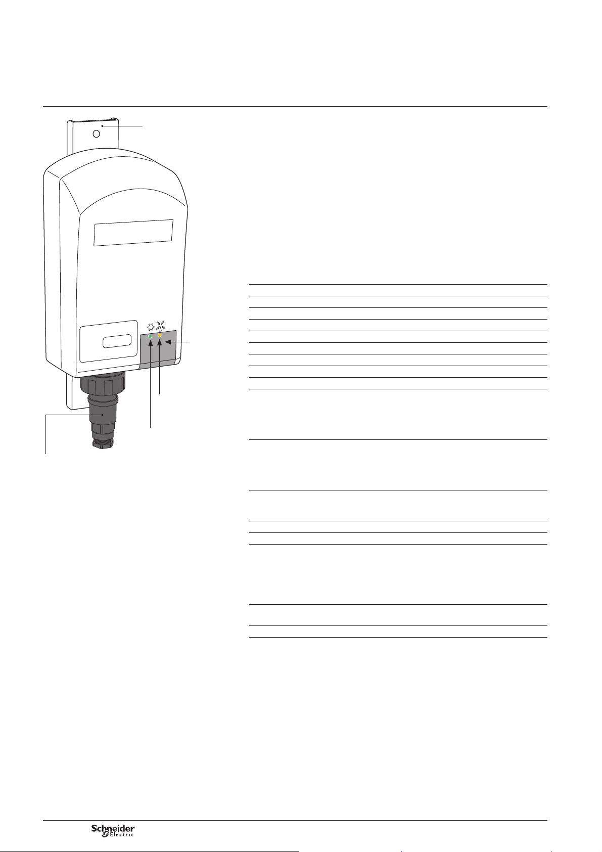
Bulgin connector:
Sensors input measurement,
Sensor output 15 Vdc power.
Unistrut™ rail adaptor
(not provided)
Infrared
communication
area
Status indicator lights
Yellow: GSM
SMS transmission
function
Green: RUN
operating function
Purpose
This document is the user manual for the W310 wireless local telemetry unit.
W310 refers to the same product. In the following, only W310 will be used.
Presentation
W310 belongs to a generation of ultra-low power consumption data acquisition and
transmission products that use the GSM network.
W310 is battery-powered, making it completely self-suffi cient and extremely quick
and simple to install.
W310 comes in a robust polycarbonate box which is highly resistant to adverse
weather conditions and is connected to the signals it is monitoring by means of
a waterproof connector. It has two indicator lights which indicate the device's
operating status.
Main features
Operating temperature Between –25°C and +60°C, between 0 and 90% humidity
Protection class IP56 (IP40 for UL)
Dimensions 194.4 x 107.7 x 65.7 mm
Power supply Lithium-thionyl-Chloride 3.6 V (size D) cell
Battery life Up to 10 years depending on type of use
Connection IP68 waterproof connector
Local link IrDA infrared (9600 bauds no-parity 8 bits)
GSM Quadri-band (850, 900, 1800, 1900 MHz)
GSM antenna Internal
Digital inputs b 4 digital inputs usable as pulse counting (32 bits, 50 Hz,
minimum pulse width: 10 ms)
b Flow calculation, close contact time calculation
b Measuring voltage: ~ 3.3 V
b Reading current: ~ 3 A
Analogue inputs 4 universal analogue inputs:
b 0-100 mV, 0-1 V, ±10 V, ±10 Vpp
b 0-20 mA, 4-20 mA (W310 is able to power sensors
(supply voltage = 15 V))
b Resistor (0-2000 ), PT1000, PT100 (2 and 3 wire)
Other link Modbus Master RS485 (1200 – 38400 bauds)
W310 is able to power Modbus sensors
(supply voltage = 15 V)
Measurement resolution 16 bits
Accuracy < 0.1% (see features in detail)
Security b SIM card PIN number management
b Confi guration backed up in non volatile EEPROM
memory and non-volatile RAM
b “Watchdog timer”
b Overvoltage protection and polarity reversal protection
on input
Conformity b CE
b UL61010-1
RoHS Compliant
6
NT00196-EN-03
Page 7

W310 (Brio)
Overview
Self-suffi ciency
W310 has been developed using ultra-low power consumption technology which
enables it to be selfpowered for up to 10 years.
W310's self-powered lifespan is closely connected to the conditions in which it is
used, especially transmission frequency. Schneider Electric Telecontrol can assess
the probable lifespan of the battery according to the type of use to which it will be put.
The table below indicates probable lifespans for several typical hypothetical scenarios:
SMS transmission
frequency
1 / month* 3 Hz 10 years
1 / week 3 Hz 8 years
1 / day 3 Hz 5 years
3.6 V Supply voltage Consumption Activities carried out by W310
Sleep mode <30 A At 25°C, Clock running,
Read mode <30 mA Reading analogue channels
GSM transmission mode 400 mA Sending the SMS(s) (*)
(*) Real-life measurements have shown that the system can transmit more than 12000 SMS
messages without a change of battery (the consumption in this test is essentially due to the
communication).
Please note that by nature 4-20mA sensors cause a high level of consumption
when supplied by the W310. The longer it takes for the sensor to stabilise,
the higher the consumption will be.
Count frequency Lifespan (average)
1 Hz counting on on-off inputs.
(Except 4/20 mA and Modbus sensors)
Operating principles
W310 is based on simple operating principles:
b Programmable frequency acquisition and logging of various physical
measurements (metering, voltages, 4-20 mA sensing probes, temperatures, etc.).
Note that W310 is able to supply power to 4-20mA sensing probes. After taking
readings, the W310 then implements its alarm detection function.
b Programmable frequency transmission (in SMS form) of the data logged.
Data reception is provided by a master station such as Kerwin supervisor of
Schneider Electric Telecontrol.
Note that in the event of an alarm, a transmission will be sent as soon as the alarm
status is detected during a logging. To facilitate diagnostic of whichever element
is in alarm status, the W310 transmits all data in the memory at the same time
as it transmits the alarm.
b In sleep mode
v Real time “Detection” of changes in status of the digital inputs, with transfer to
“Read” mode
v Pulse counting (50 Hz max.) on all digital inputs.
b Programmable frequency diagnostic of operating settings (Battery voltage,
GSM signal strength, etc.): these settings are intended for monitoring and preventive
maintenance of the equipment.
Note: to be able to receive SMS messages sent by W310, the master station must
be equipped with a GSM modem in reception mode (cf. “Confi guration of the Kerwin
master station”).
NT00196-EN-03
7
Page 8
W310 (Brio)
Overview
Operating modes
W310 essentially operates in two modes, “Sleep” mode and “Awake” mode.
It is important to note that as W310 is an ultra-low power consumption product,
it is in “sleep” mode most of the time.
Its functions are activated under the following conditions:
b When it is the time programmed for acquisition or transmission
b When the activating magnet is used (A suffi ciently powerful magnet or the magnet
located in the infrared interface)
b When a change occurs on the status of one digital input (depending on the settings
of the digital inputs).
In particular, the system cannot be activated by a GSM call, as this would involve a
“standby” level of power consumption that would not be compatible with the lifespan
of the battery. These energy saving principles have been adopted in order to obtain
a maximal battery lifetime.
When the W310 is not in operation, for example when in transit, it can be set to
“transport”mode. While this mode is activated, W310 doesn't perform any
acquisition nor data transmission.
Function indicator lights
Two indicator lights are used to indicate the device's operating modes:
Light Colour Function Notes
RUN Green
GSM Yellow
Indicates the processor's activity:
b In “sleep” mode, a very short fl ash
every second.
b In “transport” mode, one fl ash every two
seconds.
b Quick blink when the magnet is detected
(local mode activation W310).
b ON during acquisition and transmission
periods.
b During dialogue with Kervisu, fl ashes
at each query during IrDA connection.
Indicates activity of the GSM function:
b Short fl ash (1/10 s) each second
during GSM communication.
b "Long" signal (1s x 1) to indicate SMS
successfully sent ending communication.
b Variable length signal to indicate GSM
reception strength (only when reading GSM
signal strength).
In sleep mode, the fl ash each
second is only noticeable
in semi-darkness; it is more
visible on each minute.
During data transmission,
the number of fl ashes
corresponds to the time
taken to transmit the SMS(s).
8
NT00196-EN-03
Page 9
W310 (Brio)
DE59635
Installation
Prerequisites
Please refer to the W310 Installation Guide for the details of the installation steps.
In order to operate the W310, you will need:
b Kervisu software version 1.9.4.1 or higher with the confi guration fi le for W310
used by Kervisu (Ref.: KvBRIO_6_Fr.CFG on the CD-ROM delivered with the product).
AntennaSIM card slot
b A Kervin master station, version 4.1.X or higher (applying a 3.6.2 patch to Kerwin
version 3.6 will also allow SMS messages from W310 version 5 or higher to be received).
b An activated SIM card with SMS capability.
b A USB/IrDA interface supplied by Schneider Electric Telecontrol
(Ref.: 0BRIOKIRDA-USB) for which the drivers are loaded onto the PC in accordance
with the instructions in chapter “Setting up the infrared / USB interface” and a magnet
(integrated in the IrDA interface).
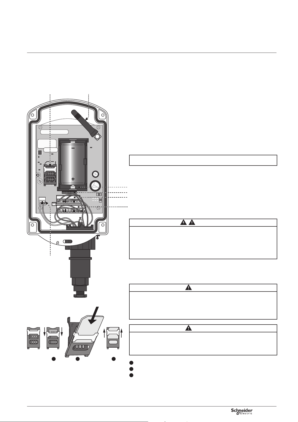
Internal view of W310
The waterproof box is screwed down using four head screws: after loosening
the four screws completely, the cover can be removed by inserting a screwdriver
into the attachment hole at the top.
Take care to keep the cover parallel with the box when removing, so that it can be
removed easily and without damaging it.
RS485 connector
DE59639
1 2 3
Battery holder
For factory test
Analogue input terminal block
Digital input terminal block
WARNING
ONLY QUALIFIED PERSON TO OPEN THE EQUIPMENT
It's forbidden to open the equipment by an operator:
Battery or SIM card replacement must be necessarily carried out by returning
the product to the factory or by a qualifi ed person.
Failure to follow these instructions can result in serious injury or equipment
damage.
Insertion of SIM card
CAUTION
PIN CODE INFORMATION
Before the insertion of the SIM card, you must check the correspondence between
PIN codes or inhibit the PIN code of the card to be used.
Failure to follow these instructions can result in invalidate the SIM card.
Then you will need to request the PUK code from the operator!
CAUTION
INSERTION OF SIM CARD
Never insert or extract a SIM card when W310 is in communication
(indicator lit on or blinking).
Failure to follow these instructions can result in equipment destruction.
1
Unlock the SIM card slot by moving down the metal part to the bottom.
2
Insert the SIM card inside the shutter.
3
Pull down the SIM card shutter toward the support and lock it by moving up
the metal part.
NT00196-EN-03
9
Page 10
W310 (Brio)
WARNING
ELECTRICAL SHOCK RISK
All wiring must be carried out in accordance with
industry standards. NEVER ALLOW BARE WIRES
TO COME INTO CONTACT WITH EACH OTHER.
The sensors or the power used with the W310 must
answer specifi cations SELV (Safety Extra Low Voltage).
They must be obligatorily installed by qualifi ed
personnel.
Failure to follow these instructions can result
in death, in serious injury or equipment damage.
CAUTION
RECOMMENDATION ON SENSORS CONNECTION
The total length wiring must not exceed 3 meters.
The wiring must be twisted pair armed type to connect
the sensor.
Failure to follow these instructions can result
in equipment measurement failure.
(*) BUCCANER connector ref.: PX0745/S, Manufacturer:
BULGIN (UK).
This connector is supplied as standard with the W310
but can also be ordered directly from Schneider Electric
Telecontrol or via the electronic distribution system.
Installation
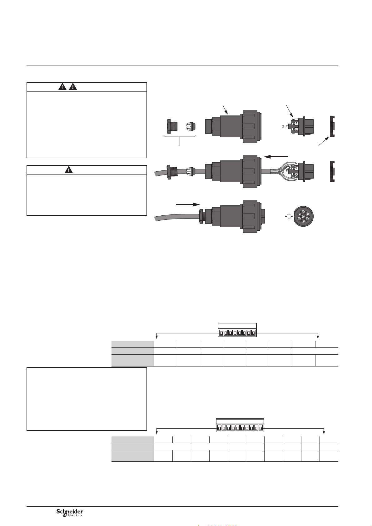
Connectors
Connectors
The W310 is equipped with a 7-point IP68 fi xed female connector (*) which can be
screwed directly onto the ends of the cables, with no welding or crimping.
The connector can be detached using a screw-off (anti-clockwise) threaded bolt.
Flex body moulding Contact insert
DE59646
Gland nut Insert retaining ring
2
1
7
6
The 7 pins, which have their numbers printed in relief on the connecting piece,
are for connecting to the signals that are to be read.
The 7 pins are connected to wires inside the box which are coloured according to
the international code and can be wired to the terminal blocks when required.
Schneider Electric Telecontrol delivers the W310 pre-wired according to various
different standard schemes (The different schemes are described in the Appendices).
3
4
5
Terminal no. 1 2 3 4 5 6 7 8
Printed ref. A1(*) A2 A3 A4
Corresponding
reading
NB: please take note of the polarity of the signals,
especially for sensors supplied by the W310
(two-wire sensors should be connected between
the supply signal and the relative input, the sensor's +
to the power, the sensor's – to the signal terminal of
the channel in question).
NB: please take note of the correspondence between
the physical signals and the software channels
confi guration. (See the channels confi guration screens
on Local confi guration of W310 (Kervisu) chapter).
Terminal no. 1 2 3 4 5 6 7 8 9 10
Printed ref. DI1 DI2 DI3 DI4 15V(*) 15V(*)
Corresponding
reading
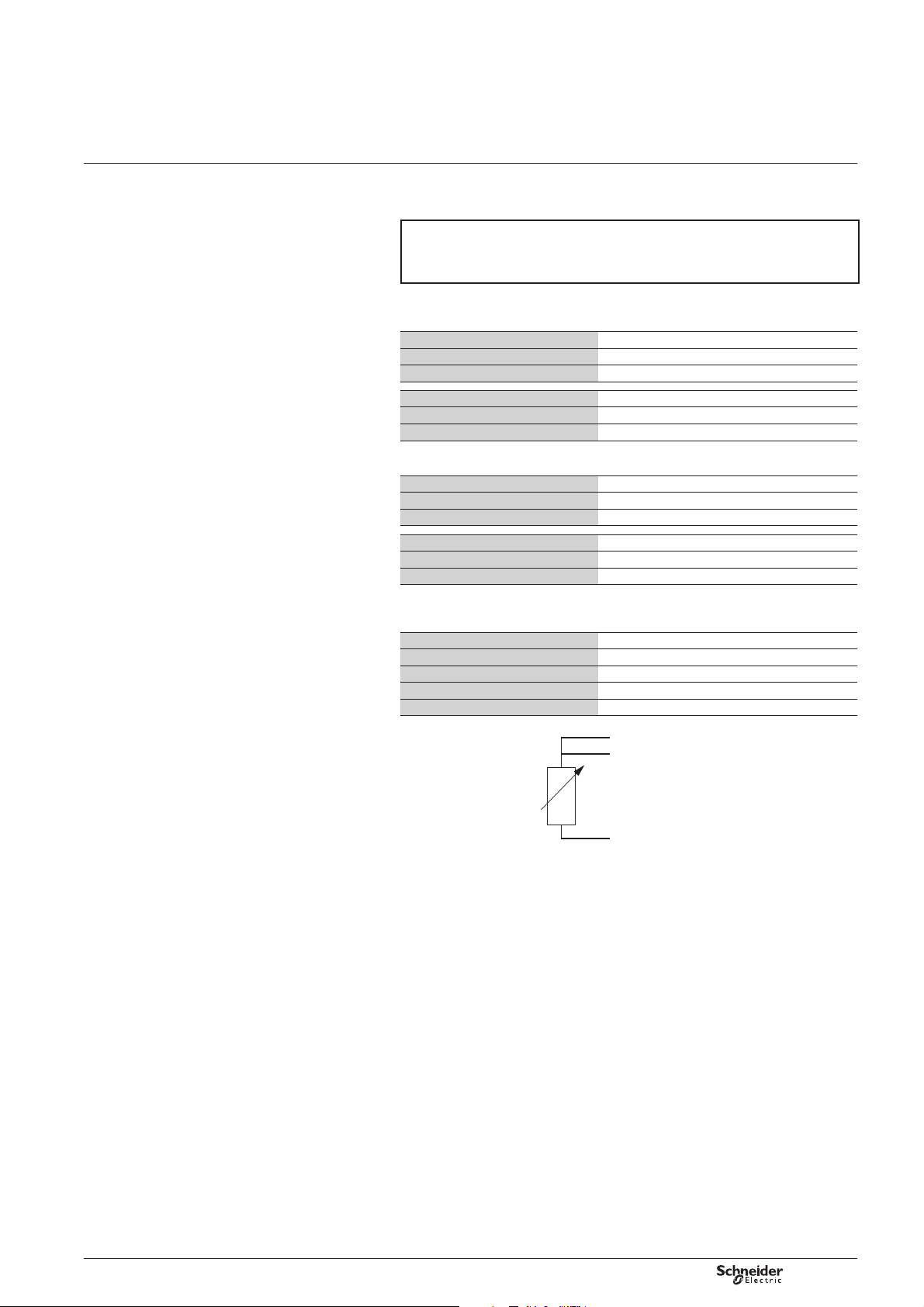
Analogue input internal terminal block
The detachable terminal block has 8 terminals. Each of the analogue channels
corresponds to two terminals (signal and reference). The 4 analogue channels all
have the same reference.
Reference screen-printed on the electronic card: ANALOG INPUT
Ana 1
signal
(*) A1: Analogue Input 1
AGND Ana 2
signal
AGND Ana 3
signal
AGND Ana 4
signal
AGND
Digital input internal terminal block
The detachable terminal block has 10 terminals. Each of the inputs corresponds to
two terminals (signal and reference). The 4 digital channels all have the same
reference. It also has 2 terminals that can supply power to a 4-20mA sensing probe.
Reference screen-printed on the electronic card: DIGITAL INPUT
EL/Cpt 1GND EL/Cpt 2GND EL/Cpt 3GND EL/Cpt 4GND Sensor
(*) For 4-20 mA and Modbus sensors.
power
Sensor
power
10
NT00196-EN-03
Page 11
W310 (Brio)
Installation
Connectors
Connections for the various types of sensor
Digital Input or Counting
NB: the digital inputs are fi ltered by an RC/Hysteresis device, but they are high
impedance in order to limit the power consumption; the reading voltage is
approximately 3.3 V and the reading current is 3 A.
The connected contact must therefore be potential-free and leakage-free.
Wire between DI (1 to 4) and GND internal block DIGITAL INPUT
4-20 mA Analogue Input
2-wire passive: sensor block Internal W310 block
+ +15V (terminal 9 or 10, Digital Input block)
– Ai (i = 1 to 4) (terminal 1, 3, 5, 7 on Analog Input block)
Active sensor block Internal W310 block
+ Ai (i = 1 to 4) (terminal 1, 3, 5, 7 on Analog Input block)
– AGND (terminal 2, 4, 6, 8 on Analog Input block)
Voltage, Resistance, Platinium sensor analogue inputs
Voltage sensor block Internal W310 block
+ Ai (i = 1 to 4) (terminal 1, 3, 5, 7 on Analog Input block)
– AGND (terminal 2, 4, 6, 8 on Analog Input block)
Resistance, Platinium sensor block Internal W310 block
Terminal 1 (*) Ai (i = 1 to 4) (terminal 1, 3, 5, 7 on Analog Input block)
Terminal 2 (*) AGND (terminal 2, 4, 6, 8 on Analog Input block)
(*): any polarity
Modbus sensor
Modbus sensor block Internal W310 block
Power + +15V (terminal 9 or 10 on Digital Input block)
Power – GND (terminal 2, 4, 6, 8 on Digital Input block)
RS485 + RS+ (RS485 block 2 terminal)
RS485 – RS- (RS485 block 2 terminal)
PT100 sensor – 3 wires:
GND
A
i + 1
R
A
i
NT00196-EN-03
11
Page 12

W310 (Brio)
Commissioning
Types of configuration
Checks before starting
For your activation to run smoothly, you are strongly advised to check that
the following conditions have been met:
Please note that the checks below are not required if the product has been factory
pre-confi gured (the fi nal quality control sheet will certify that the settings have been
checked).
b The battery installed should be brand new and not used at all (this can be quickly
verifi ed using a multimeter, which should give a reading between 3.6 V and 3.7 V).
You are strongly advised to attach a label with the date on which the battery is fi rst used.
b The analogue signals that are to be connected are compatible with the inputs used
(you should pay particular attention to the connection direction when connecting
4-20 mA sensors when these are being supplied by the W310).
b The digital signals connected are completely potential free: zero voltage should
be recorded at the start for each pair (before connection)..
b The SIM card should be correctly inserted in its holder, which should be locked
in place.
In order for the confi guration and test to be carried out smoothly, ensure that:
b The device is fi tted with a SIM card for which the account has been activated
(this can easily be checked by sending an SMS with the SIM card inserted in a
mobile phone).
b On the supervisor, a site has been created with a phone number corresponding to
the one of the SIM card inserted in the tested W310 (this is the condition which
determines that the data sent by W310 is registered). The number is usually provided
by the network operator when the card is delivered. If you are unsure of the number,
it will be displayed when an SMS sent from the SIM card is received.
NB: Kerwin versions 4.1 and higher allow autoconfi guration of a W310 site
(in that case, the site is automatically created in Kerwin Supervisor with W310
phone number as soon as a SMS coming from that W310 is received).
Types of confi guration
W310 has been designed to be set up very simply. There are two different
confi guration possibilities:
Factory pre-confi guration
In this instance, commissioning on-site consists of connecting the signals, fi xing
the item in place and running a diagnostic transmission. The same method will be
used for repeat installations where all the operating settings are pre-confi gured in
advance (see details of the procedure in paragraph “Activating a diagnostic SMS
send” of this chapter).
User confi guration
This solution is more fl exible and allows all the operating settings to be confi gured
on-site. It requires use of a PC equipped with Kervisu software (Version 1.9.4.1 or
higher). Details of the procedure and the different possibilities for confi guration are
given below.
d In both case, W310 must be activated.
W310 is delivered in the “transport” mode to prevent any energy consumption
before commissioning. In this mode (one weak fl ash every 2 seconds), neither data
capture nor SMS transmission is activated.
The operation described hereafter switches the W310 from the transport mode
to the active mode and allows local communication.
12
NT00196-EN-03
Page 13
W310 (Brio)
DE59643
Detection area
Infrared
communication
area
Green
indicator
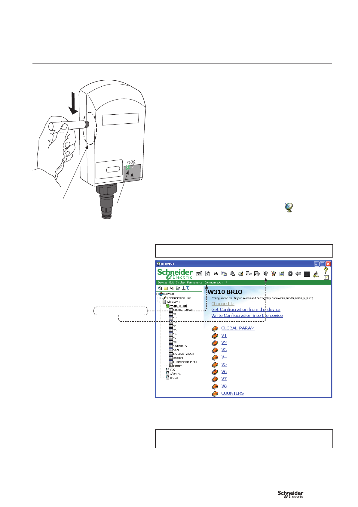
Commissioning
Wake up W310 and local activation
of the dialogue
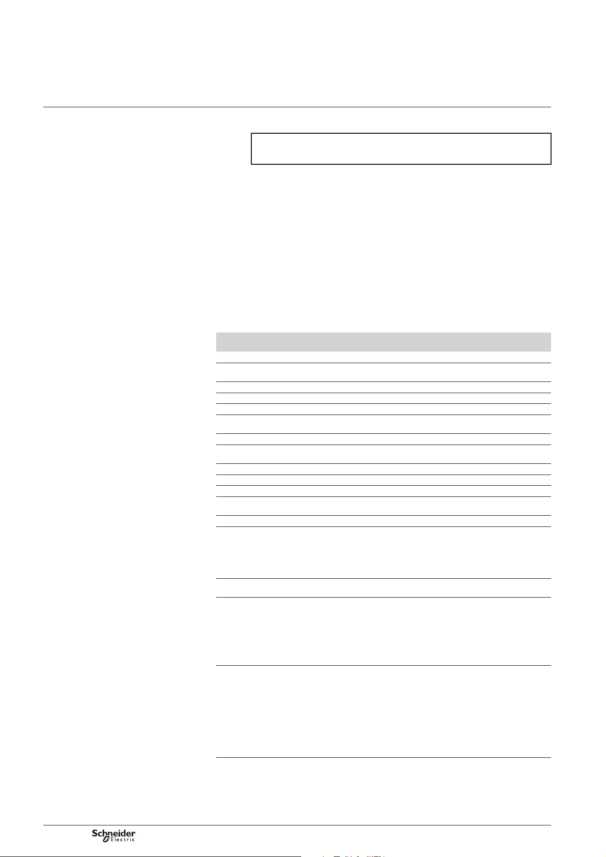
Wake up W310 and local activation of the dialogue
The W310 is always in sleep mode except during acquisition and transmission
phases, therefore it is necessary to activate it before being able to initiate a dialogue.
The port is activated by holding a magnet (located in the infrared interface supplied
by Schneider Electric Telecontrol) against the left side of the device for a few seconds
(5 s), as shown in the photo above. When the W310 is activated, the green indicator
light will go on.
When the green light is on, the W310 is ready to dialogue with Kervisu,
and you can then proceed with confi guration according to the instructions
in Chapter “Local confi guration of W310 (Kervisu)”.
Please note that once it has been activated, the W310 will be in communication
standby mode for 2 minutes. If there is no dialogue during that time, it will automatically
revert to sleep mode. It will then need to be activated again in order to start the dialogue.
When the green indicator light (on the left) is fl ashing, this shows that communication
is in progress. The light changes status at each data exchange.
The infrared port is located near the two indicator lights to the right of the “W310” mark.
It uses the IrDA protocol.
Schneider Electric Telecontrol provides a USB/IrDA cable as standard, which can be
used on any PC that has a USB port. As with all USB devices, it requires drivers,
which need to be installed as per the procedure described in appendix.
The Kervisu connection is carried out either by clicking on the
“connect” from the “communication” menu, as shown in the screen shot below.
The icon should then change colour and you will be able to choose one of the pages
suggested: “confi guration”, “channel 1” , etc. If the connection icon (dish aerial) does
not change colour, it means the infrared cable is not connected or Kervisu has not
been correctly confi gured (see chapter Appendices).
NB: from version 1.10.0.0 of Kervisu, the IrDA link must be positioned in order
to communicate with the W310 awake to allow the connection.
, or by selecting
Connecting to the W310
The following indicates that communication between Kervisu and the W310
has been successful:
b The values on the various screens are refreshed and appear in bold.
b The green light on the W310 fl ashes simultaneously with the data exchange.
Note: the link will only be established if the pre-requisites mentioned in page 9
have been met, especially setting up the infrared interface on the PC, and
registering the W310 in the Kervisu confi gurator (cf. Appendices).
NT00196-EN-03
13
Page 14
W310 (Brio)
Note: diagnostic values OP, RT, CB
and CI are valid from W310 fi rmware
version 6.20 and higher.
Commissioning
Activating a diagnostic SMS send
Activating a diagnostic SMS send
NB: since it is coded, a diagnostic SMS can only be sent to a suitable supervisor
(Kerwin type); it is no sense to send a diagnostic SMS to a cellular phone
(except for tests).
Defi nition of a diagnostic SMS
A diagnostic SMS can be sent automatically at a programmable frequency or
on demand.
Diagnostic data are intended for monitoring and preventive maintenance
of the W310 equipment.
A diagnostic SMS includes:
b The current values of the confi gured variables
b The diagnostic values (system data available on every W310).
In the SMS, diagnostic values are identifi ed with a 2 letters mnemonic.
Kerwin supervisor matches these mnemonics with comprehensive labels
(those labels identify the W310 system variables on Kerwin supervisor side).
Each label has a default value but can be changed as the user wants.
The relation between the mnemonic and the label is specifi ed in the KERWIN32.CFG
fi le (which stands in the Kerwin32 installation directory) in the [Brio diagnostic] section.
Mnemo Corresponding label
RL Radio Level GSM received signal strength (in dBm)
BL Battery Level Minimum voltage reading of the battery during the previous data
SV Software Version Numeric value for the software version (e.g.: 510 => 5.1.0)
SA Send Attempts Number of attempts at sending SMS
SS SMS Sent Number of SMS actually sent to the GSM network
MC Gaz Consumption Calculation of the total amount of energy consumed from the delivery
SE System Error Numeric value of the last system error (See system error table)
ST Session Time Total number of seconds the W310 modem has been taking
LC Last Confi guration Date of last change in the W310 confi guration
NV Number of Variables Maximum number of variables (usually 8)
SN Serial Number Serial number
AV Application Version Numeric value corresponding to the confi guration loaded in the W310
SR SMS Received W310 received SMS counter
OP OPerator ID Operator ID number
RT Registration Time This fi eld represents time in seconds encountered between the modem
CB Current Bands This fi eld represents the frequencies band or the group of two
CI Cell I
in Kerwin supervisor
dentifi cation Cell ID number. This information is transmitted in a decimal format
Description
transmission phase (in Volts)
of the W310 (x 100 A)
to send SMS
before the delivery
b MCC: fi rst 3 digits (Mobile Country Code)
b MNC: 2 last digits (Mobile Network Code)
The information sent within a diagnostic SMS concerns the operator
to which the W310 is registered when the SMS is sent. This operator
code is memorized on the W310 and is displayed on Kervisu GSM page
start (beginning of the SMS session) and the registration on a network
frequencies bands chosen by the modem to register on the network.
This fi eld is transmitted on a numerical format and matches a fi eld
of bits defi ning the different frequencies which are compatible with
the modem.
1 : 0000 0001 GSM 900 MHz
2 : 0000 0010 GSM 1800 MHz
4 : 0000 0100 GSM 1900 MHz
(unsigned 4 bytes (2 words)):
b 1st word : LAC: Location Area Code.
In each network, cells are grouped by geographical regions which are
attached to a LAC. These regions can be more or less big depending
on the density of the covered surface, on average some dozens of
kilometers.
b 2nd word: CI: Cell ID
Inside a LAC, each cell owns a unique ID (CI). Information transmitted
on a diagnostic SMS matches the cell where the W310 is registered
at the moment when the SMS is sent.
14
NT00196-EN-03
Page 15
W310 (Brio)
DE59644
Maintain
during 10 s
Detection area
Indicator
lights
Commissioning
Activating a diagnostic SMS send
When the W310 has been factory pre-confi gured
A factory pre-confi guration means that Schneider Electric Telecontrol will have
all the confi guration data relating to the site for which the W310 is to be used:
b What signals are to be connected to the W310 (which determines which channels
will be registered, along with their type)
b The frequency with which the data acquisitions are to be carried out
b The frequency with which the readings will be transmitted by SMS
b The SIM card’s PIN number
b The receiving telephone number(s) for the SMS messages.
The customer will also have provided Schneider Electric Telecontrol with the SIM card
and requested its activation in order for Schneider Electric Telecontrol to insert it
at the factory before delivery.
If all the above conditions have been met, you simply need to hold the activating
magnet in position for at least 10 seconds in order to activate the following actions:
b Acquisition via the registered channels
b Sending a diagnostic SMS
b Sending a diagnostic SMS including:
v values of the confi gured channels
v values of the diagnostic parameters.
When the green LED fl ashes (5 Hz), this shows that W310 has detected the presence
of the magnet.
One fl ash per second of the yellow LED indicates that the request for a diagnostic
SMS has been registered and is being transmitted.
If the SMS transmission is successful, the fi nal fl ash lasts for a whole second.
If however the transmission is not successful, the W310 will retry for a further
2 minutes, after which it will abandon the attempt. It will only retry again if:
b The current date is a logging date.
b The diagnostic procedure is reactivated (you must wait until W310 has returned
to sleep mode – one fl ash per second on the green LED).
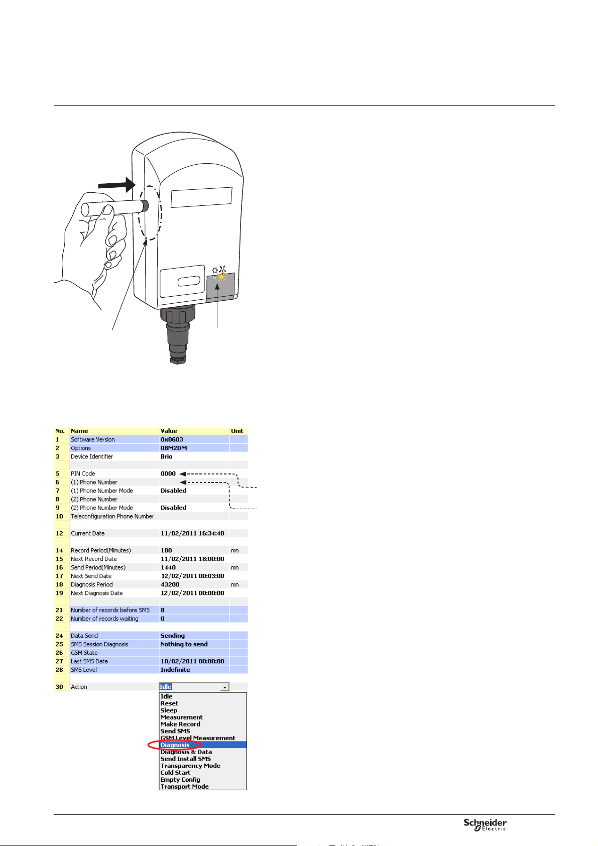
When the W310 has not been factory pre-confi gured
In this case, before being able to carry out a test SMS transmission, you will need
to make the local connection (with Kervisu) (see chapter “Wake up W310 and/or
local activation of the dialogue”), so as to confi gure the settings which until will
enable an SMS to be transmitted:
b Be sure that at least one measurement channel is confi gured (see Channels 1 to 8
screen)
b The SIM card’s PIN code
b The phone number to call for the Kerwin supervisor (if there is no mobile phone
number)
b Enter the PIN code
b Enter the Kerwin receiving number for the SMS, along with its mode
(Data or Data + Alarms)
b In the “Action” fi eld, select the command “Diagnostic”
b An SMS will be prepared and sent; you can track the send status in the “GSM action”
and “Session diagnostic” fi elds.
NT00196-EN-03
15
Page 16

W310 (Brio)
Local configuration of W310
(Kervisu)
Confi guring using Kervisu
The W310 is confi gured using Kervisu, on a PC equipped with the infrared interface
cable.
This guide gives details of:
b The installation procedure for the infrared interface, chapter Appendices.
b The procedure for registering W310, chapter Appendices.
b The procedure for activating W310’s to communicate with Kervisu, chapter
“Commissioning”.
All the actions needed for confi guration are carried out under 4 section headings,
which correspond to the four screens described below:
Confi guration screen
This is where all the general operating settings are defi ned (names, logging and
transmission frequency, telephone number, etc.).
Channels (1 to 8) screen
This is where the variables to be logged are defi ned: their names, types, slope, shift,
modes and alarm thresholds.
System screen
For the system control (traceability) and system settings.
Counters screen
Where the indexes for the digital input counters (DI1 to DI4) can be pre-loaded,
whether they are used for pulse counting or time counting.
Various commands can also be run from these screens, such as SMS send, reading
GSM reception signal strength.
Just to remind you…
Kervisu is the confi guration tool for W310 products.
All the device’s operating settings can be displayed in Kervisu. This paragraph
is intended for users who have not used it before:
Communication can only take place if Kervisu is in connected mode
(click on the corresponding icon
and local activation of the dialogue).
, see chapter Commissioning V Wake up W310
16
NT00196-EN-03
Page 17

W310 (Brio)
NB: all the modifi able fi elds need to have values
entered which are consistent with one other, even if
they are not going to be used. You are advised to use
short titles, as these are the titles which will be
transmitted in the SMS messages.
Local configuration of W310
(Kervisu)
Configuration screen
Name Modifi able Description
Software version No Version number of the W310 application software. This number should match
Options No Character string defi ning the various software options.
Device identifi er Yes 7-character serial number for identifying the W310.
PIN code Yes The W310 is capable of managing the PIN code, which is a 4-character code.
(1) Phone number Yes Telephone number (maximum of 12 digits, without spaces)
(1) Phone number mode Yes Transmission mode for 1st number, between:
(2) Phone number Yes Telephone number for a second recipient of data transmission if required.
(2) Phone number mode Yes Transmission mode for 2nd number
Teleconfi guration phone number Yes This is the master station from which the remote confi guration operations are carried out.
Current date Yes Enter in the format dd/mm/yy hh:mm:ss (*)
Record period Yes Number of minutes between each logging of the variables being measured
Next record date Yes Enter in the format dd/mm/yy hh:mm:ss (*)
the version of the confi guration fi le used (KvBRIO_6_En.CFG)
It is ESSENTIAL that the code corresponds to the code belonging to the card that is being used
b None: no transmission
b Data: transmission of data to the (Kerwin) master station
b Data + Alarms: transmission of data and alarms to the (Kerwin) master station
b Text alarms: transmission of alarms in SMS form to a mobile phone.
Note that Kerwin does not read SMS text messages.
W310 answers to Teleconfi guration SMS:
b Either to the phone number mentionned in this fi eld
b Or to the sender of the teleconfi guration SMS.
The Teleconfi guration tool, can specify in the SMS it sends to the W310 which telephone number
should receive the answer of the W310 (the one specifi ed in this fi eld (default) or another one
specifi ed in the Teleconfi guration SMS).
(Programme between 1 and 10080, equivalent to 7 days max.).
NB: when the logging interval is changed, the logging memory is cleared; when this happens,
you are therefore advised to run a send if you do not wish to lose any data.
This enables the date for the fi rst logging to be set.
After a logging, or when the logging interval is changed, W310 automatically
updates the date.
NT00196-EN-03
17
Page 18

W310 (Brio)
Local configuration of W310
(Kervisu)
Configuration screen
Name Modifi able Description
Send period Yes Number of minutes between 2 regular transmissions.
Next send date Yes This variable tells the user the date of the next SMS message(s) transmission.
Diagnostic interval Yes Number of minutes between 2 diagnostic transmissions
Date of next diagnostic Yes Date and time of next diagnostic; the date entered must correspond to a scheduled
Number of logs before
sending the SMS
Number of logs ready to send No Number of logs present in the system memory which have not yet been sent.
GSM action No Indicates the status of the GMS function, which will be either:
GSM diagnostic No Gives the result of a transmission request (automatic or manual):
SMS state No Shows the status of the SMS transmission dialer.
Date of last SMS transmission No Shows the date when the last SMS was sent.
GSM level No Shows the reception strength at the transmission of the last SMS or in real time during the test
Command Yes This refers to a menu which allows you to send various commands to the device.
No This refers to the relationship between the transmission interval and the logging interval.
This number should be a multiple of the logging interval.
W310 automatically limits the number if the value entered is too high for W310’s storage capacity.
This date is especially useful for synchronising the transmission date to a precise schedule.
It will be repeated for each transmission, except if there is an alarm or the fi le is full.
The date should coincide with a logging date.
E.g.: if a logging interval of 60 mins is specifi ed, with a transmission interval of 1440 mins (1 day)
and a transmission time of 05h00, the transmission will take place every day at 5am.
(see chapter Overview V Operating principles)
transmission date.
In other words, the number of logs sent with each transmission (when there is no alarm situation).
b Data not sent
b Send in progress
b GSM standby mode: wait during a confi gurable temporization (precede the reading of
received SMS)
b SMS search: look for the SMS stored in the SIM card or in the modem.
b SMS processing: SMS processing and deletion
b Complete session: the device has terminated the last command to be sent to the GSM
network. The result is shown under the section “GSM Diagnostic”.
b GSM signal strength: the device is reading the GSM reception signal strength.
b -------- : Diagnostic not yet determined
b Nothing to send: no recipient confi gured or no variable declared
b SIM card problem: SIM card not present or not detected
b Wrong PIN code: failure when writing the PIN code
b PIN code problem: there is less than 3 tries left for entering the PIN code, as a result SMS
sending is locked (to unlock the W310 PIN code protection and allow again SMS sending
see chapter Local confi guration of W310 V
b Wrong tel. number: no telephone number or bad format
b Send failure: the SMS sending is interrupted by the W310 after 3 minutes
b SMS sent: the last SMS requested was transmitted to the network
b Too many failures: after 4 successive sessions of SMS sending having failed, the sending
of SMS is blocked (the number of failure is set to zero every day at 12am and 12pm).
However it is possible to force the sending of SMS at any moment by using the commands
(Send SMS, Diagnostic,...).
GSM strength command. The reception quality is shown as one of the following:
Very good; Good; Medium; Weak; Very weak; Too weak
The objective measurement in decibels (dBm) is also given for the memory.,
This varies between – 51 dBm (very strong signal) and – 110 dBm (very weak signal).
The dBm is the usual unit of measurement of electromagnetic fi eld strength.
It is equivalent to 10*LOG(P) where P is the power received expressed in milliwatts.
To do this, click on the fi eld, select the command you require and wait for it to run before using
another command.
The most frequently used commands are:
Read channels; Test GSM strength; Send SMS; Sleep; Etc.
Details of these commands are given in the command table below
(*) : Depending on the date format selected (Kervisu: Devices – Options – Time and Date format,
Format type).
GSM screen)
18
d IMPORTANT
Some special characters must not be used for the titles, otherwise the SMS messages may not
be sent.
The following characters can be used: @ _ - : ‘ / =
Do not use the following characters: # 2 & \ ? % + ( ) ‘’
NT00196-EN-03
Page 19

W310 (Brio)
Local configuration of W310
(Kervisu)
Configuration screen
Table of commands
Name Description
Idle No command running
Sleep Tells the device to return to sleep mode (if there is no transmission or measurement in progress);
Measurement The W310 gets the data from the channels; each time this command is run,
Send SMS The device sends the waiting data to the master station. This command should be run when
GSM level measurement The device reads the GSM signal strength for approximately 2 minutes.
Empty confi guration All the settings return to their “Factory” confi guration.
Transport mode Places the W310 in sleep mode. It can only be activated using the magnet, as outlined
Diagnostic Initiates send of a diagnostic SMS (diagnostic data + variable current value)
Diagnostic & Data Initiates send of a diagnostic SMS and data to send
Send install SMS Send diagnostic data + install data (software version, options,…) + variable current value
Transparent mode Used during maintenance for direct dialogue with the GSM module
Reset Used during maintenance, in particular when loading a new software version
The fi eld assumes this value as soon as a command has been processed.
it will return to awake mode:
b When activated (See chapter Commissioning V Wake up W310 and local activation of the
dialogue)
b If the current date is a logging date
b When activated by a magnet.
the values for the different channels will be displayed in the value fi eld on each channel screen.
This command can be used to check the wiring and that the sensors are functioning properly.
you wish to transmit data that is ready to the master station.
If a “send SMS” command is run when there are no logs waiting to be sent, W310 will not
d
send any data, but will send a Diagnostic SMS.
This command can be used to unblock a blocked GSM transmission
(diagnostic: too many failures)
The value appears in the “GSM strength” fi eld.
It can also be seen from the GSM indicator light, which lights up in proportion to the signal
strength (the longer the light is on, the better the signal quality).
NB: it is essential that this command is run after inserting a battery if the device has been
without a battery for several minutes, especially when fi rst activating, if the battery is delivered
separately.
(see chapter Commissioning V Wake up W310).
This mode is used to reduce power consumption and to prevent any transmission attempt.
NT00196-EN-03
19
Page 20

W310 (Brio)
NB: the titles entered on this screen are restricted
to 7 characters, so as to avoid lengthy SMS
transmissions; a longer, more explanatory title
can be entered in the Kerwin master station.
Local configuration of W310
(Kervisu)
Channels (1 to 8) screen
Name Modifi able Description
Current Date No Date and time on W310’s real time clock
Action (Command) Yes See the table of commands previous page
Var. Name Yes Channel title, maximum 7 characters long.
Unit Yes Unit used for display (5 characters maximum) and during transmission of an alarm in SMS text
Var. Type Yes This refers to the type of channel, selected from the list of available types
Value Yes Value of the variable at the last reading. The value as displayed takes into account the type,
Status No Indicates any anomalies encountered during acquisition of the variable
Slope Yes Coeffi cient to be applied to the value to bring it in line with the required units.
Shift (Lag. Offset) Yes Lag to be applied to the value.
Data format Yes Indicates the format in which the values for this channel will be sent (during transmission
This title is transmitted in full to the master station; therefore you are advised to choose very
short titles.
format.
which is described in chapter following page.
NB: if this fi eld is set to “None”, it means that this channel is not in use by W310
(no readings or transmissions associated with the channel).
slope and lag.
(e.g. Modbus timeout for digital sensors).
The default slope value is 1.
The slope is used particularly for 4-20 mA sensors, as it enables the sensor’s scale to be defi ned.
For 4-20 mA types, the value is given between 0 (4 mA) and 1 (20 mA). For example, if you are
using a 600 bar pressure sensor, a slope of 600 will provide the value directly in bars.
The lag is usually nil and allows sensor errors to be corrected.
of the readings history (to the supervisor) or of alarms (to the supervisor or to a mobile phone
as an SMS text message).
The choices available are:
0.: whole number
0.0: fl oating point number with one decimal place
0.00: fl oating point number with two decimal places
0.000: fl oating point number with three decimal places.
20
NT00196-EN-03
Page 21

W310 (Brio)
Local configuration of W310
(Kervisu)
Channels (1 to 8) screen
Name Modifi able Description
Stabilization time Yes Supply time of the sensor in 1/10 s (+15V) before acquisition
Type of alarm Yes Choose from the 4 possibilities:
Hysteresis Yes Hysteresis value registered when returning to normal. The hysteresis is defi ned in the same
Upper threshold Yes Value recognised for the top threshold, whose signifi cance determines the type of alarm.
Lower threshold Yes Value recognised for the bottom threshold, whose signifi cance determines the type of alarm.
Upper critical level Yes This value is optional and is relayed to the master station to allow the alarms to be routed
Lower critical level Yes This value is optional and has the same role as the upper critical level
Send critical level Yes YES/NO fi eld to authorise sending of the critical level (*)
Upper limit class Yes Optional string of characters for identifying the alarms at the reception end
Lower limit class Yes Same as Upper limit class
Send class Yes YES/NO fi eld to authorise sending of the “class” (*)
Alarm date No Date on which the last alarm was recorded
Value in alarm No Value of the variable when the last alarm occurred (whose date of detection will be indicated
Predefi ned Type Yes Selection of a predefi ned type in the listbox to confi gure the whole parameters of the variable.
Type Name No Label of the last predefi ned type applied to the variable
Predefi ned Time Status No Status of the last predefi ned type applied:
b None: no alarm has been transmitted
b Min: W310 recognises two bottom thresholds: the upper and the lower (lowest)
b Max: W310 recognises two top thresholds: the upper (highest) and the lower
b Min-Max: W310 only recognises one top (the upper) and one bottom threshold (the lower).
units as the variable itself.
This threshold should be higher than or equal to the bottom threshold and should be defi ned
in the same units as the variable itself.
This threshold should be lower than or equal to the top threshold and should be defi ned in the
same units as the variable itself.
according to certain conditions.
as above)
(as a result, all parameters are erased)
To use this fonctionality, predefi ned types must have been uploaded earlier in factory
b Original: no parameters have been changed after the selection of the predefi ned type
b Modifi ed: at least one parameters have been changed.
(*) As these optional data items take up space in the SMS messages sent, you are advised
to disable their sending when they are not relevant.
Table of channel types
Channel type Full scale value Default format Comments
None Used to avoid sending unnecessary data when a channel is not in use
Counter 0. Sum of pulses at a digital input
Flow 0. Difference in the pulse count between two acquisitions.
Digital input 0: Open
Digital input
with wake-up
Contact closed
duration
1 V 1.0 V 0.000
+/- 10 V 10 V 0.00
10 Vpp 10 V 0.00 Peak to peak voltage calculation of an alternative signal (by detecting minimum and maximum
0-20 mA 1 0.000 Used for 0-20 mA analogue sensors. When this type is used, the terminal supplies a voltage
4-20 mA 1 0.000 Used for 4-20 mA analogue sensors. When this type is used, there is a voltage of 15 V
2000 2000 0. For a resistive sensor; value read with a current of 0.4 mA
PT100 0.0 In °C, with 2-wire wiring
3-wire PT100 0.0 In °C, with 3-wire wiring
PT1000 0.0 In °C, with 2-wire wiring
Modbus sensor 0.000 Value of a Modbus register read on a peripheral device
3V supply For maintenance only
4V supply For maintenance only
Sensor supply For maintenance only
1: Closed
0: Open
1: Closed
0.
0. The W310 is automatically woken up (to transmit an alarm or to revert to normal) if the status
0. Period in seconds during which the contact is closed
By choosing a suitable slope setting, it is possible to obtain the fl ow in minutes or in seconds.
changes.
When reverting to awake mode at a change in the on-off status, W310 carries out a reading
of all the channels (but without logging them) in order to detect any events, then sends alarm
SMS messages / returns to normal as applicable.
=> There must be an alarm associated with all channels of this type.
voltage over a 1 second period)
of 15 V and W310 waits for a certain time (confi gurable) before taking a reading.
at the terminal and W310 waits for a certain time (confi gurable) before taking a reading.
NT00196-EN-03
21
Page 22

W310 (Brio)
Local configuration of W310
(Kervisu)
Channels (1 to 8) screen
Correspondence between physical and software Channels
W310 usually enables to set up to 8 channels.
Up to 4 physical digital inputs and up to 4 physical analogue inputs can be connected.
Physical signals cannot be set on any software channels.
The relationship between physical and software channels is the following:
Physical signal
(Terminal block reference)
DI1 (Digital Input) 1, 5 Digital Input
DI2 (Digital Input) 2, 6
DI3 (Digital Input) 3, 7
DI4 (Digital Input) 4, 7
A1 (Analogue Input) 1, 5 100 mV, 1 V, ± 10 V, ± 10 Vpp
A2 (Analogue Input) 2, 6
A3 (Analogue Input) 3, 7
A4 (Analogue Input) 4, 8
RS+, RS- (RS485, JP7) Any channel Modbus sensor
Examples:
b Application with one digital input (for counting) and two 4-20 mA sensors
First possibility Second possibility
Physical signal
(Terminal block
reference)
DI1 (Digital Input) 1 Counter A1 (Analogue Input) 1 4-20 mA
A2 (Analogue Input) 2 4-20 mA A2 (Analogue Input) 2 4-20 mA
A3 (Analogue Input) 3 4-20 mA DI1 (Digital Input) 5 Counter
Channel
in Kervisu
1-8
b Application with one digital input (for counting and fl ow calculation) and
one 4-20 mA sensor
Physical signal
(Terminal block
reference)
DI1 (Digital Input) 1 Counter
A2 (Analogue Input) 2 4-20 mA
DI1 (Digital Input) 5 Flow
Channel
in Kervisu
1-8
In this specifi c case, it is not possible to use physical Analogue signal 1 (channels 1
and 5 are already confi gured in Kervisu because of digital signals wiring).
You have to wire the 4-20 sensor on A2, A3 or A4.
Possible channels
in Kervisu
With type Physical signal
(Terminal block
reference)
With type
With type
Counter
Flow
Contact close duration
0-20 mA, 4-20 mA
R 2000 , PT100, PT1000
Channel
in Kervisu
1-8
With type
22
NT00196-EN-03
Page 23

W310 (Brio)
Local configuration of W310
(Kervisu)
Channels (1 to 8) screen
Operation of alarms
W310 handles:
b 3 types of alarm: Min, Max and Min-Max
b 2 thresholds: Top and Bottom
Both thresholds can be used for each type. The top threshold must always be
higher than the bottom threshold.
For the Min-Max type, the top threshold corresponds to the upper top threshold and
the bottom threshold to the lower bottom threshold.
For the Min and Max types the top and bottom thresholds have 2 Min thresholds or
2 Max thresholds respectively. The advantage of 2 thresholds is that different
procedures can be triggered for each at the master station.
E.g.: for a level reading, the upper bottom threshold triggers a simple notifi cation at
the master station, whereas the lower bottom threshold (therefore very low) triggers
a more critical alert procedure.
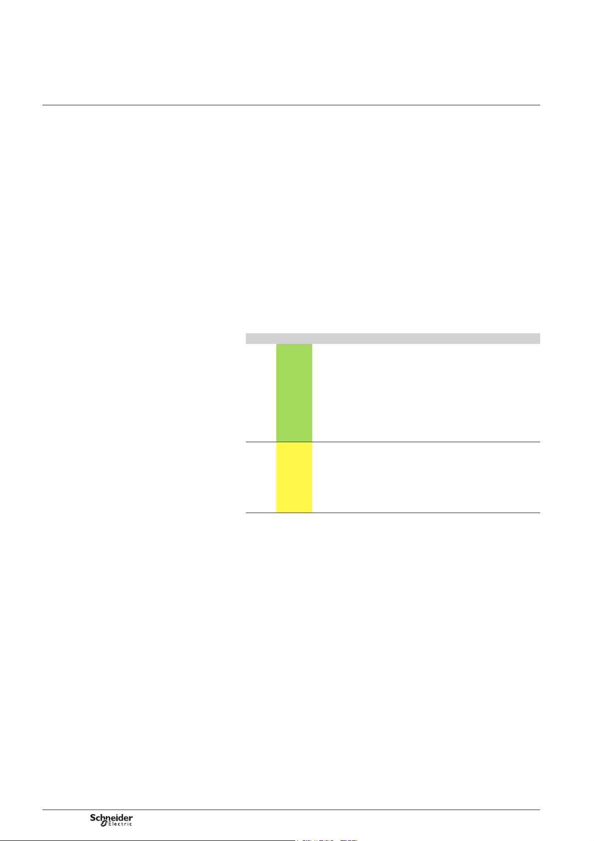
How the hysteresis operates
Alarm
DE59649EN
Top
hysteresis
Bottom
Back to
normal state
The graph above illustrates how the alarm operates in the case of a Min-Max alarm.
The variable is shown in green when it is within the normal range and in red when
it is in the alarm range. In this case a non-zero hysteresis is used, which avoids
“interference” when the value is oscillating between the two thresholds.
The hysteresis is only recognised on return to normal, i.e.the alarm is triggered
as soon as the value goes over the threshold; return to normal is when the + (lower)
hysteresis threshold or – (upper) hysteresis threshold is crossed.
NB: in order for the detection of alarms to be effective, at least one of the telephone
numbers needs to be using one of the alarm transmission modes (Data + Alarms or
Text Alarms).
The occurrence of the fault and the return to normal are routinely transmitted
whatever of the type of recipient (Supervisor or Mobile phone).
hysteresis
t
Alarms on On-Off status inputs
The channel on which you wish to register the alarm should be programmed as
a STATUS type or STATUS with wake up.
The value read is 1 for a closed (Off) contact and 0 for an open (On) contact.
This means that the alarms need to be programmed as follows:
b For an alarm on contact open (i.e. contact usually closed):
v Type of alarm: MIN
v Top threshold: 0
v Bottom threshold: 0
b For an alarm on contact closed (i.e. contact usually open):
v Type of alarm: MAX
v Top threshold: 1
v Bottom threshold: 1
Note that for digital inputs which by defi nition can only have two different statuses,
it is essential that both thresholds be programmed to the same value, otherwise
there can be no detection of the alarm or return to normal.
NT00196-EN-03
23
Page 24

W310 (Brio)
Local configuration of W310
(Kervisu)
Counters screen
System screen
Counters screen
This screen is used for controlling and pre-loading counters. Please not that the values
will change in real time when the pulses are sent.
Two types of counter can be pre-loaded:
b Pulses counters (pulses counted on digital channels 1 to 4)
b Time interval counters (equivalent to the time the contact is closed on digital
channels 1 to 4).
Pre-loading pulse counters
The counters indicate directly the number of pulses, before the slope is taken into
account. If you want to align the value indicated by a counter that sends pulses
(Energy, water, etc.), the counter’s “pulse weighting” needs to be taken into account
to convert the pulse reading.
The same “pulse weighting” will also be used to programme the slope for the variable
in question and to convert the W310 and counter readings to the same units.
For example:
For a water meter supplying pulses calibrated at 10L/pulse and displaying a value
3
in m
b 1) If you wanted the W310 to transmit the value in m3, you would need to
programme a slope of 0.01 (since one pulse is equivalent to 10 litres, or 0.01 m3).
b 2) If you wanted to align W310 with the value read on the counter, for example
3
31415 m
(100 pulses per 1 m3). You would then enter this value (3141500) on the counter
screen to obtain the desired value of 31415 m3.
, you would convert this value into pulses, giving 3141500 pulses
System screen
This screen is used for analysing W310’s internal data.
24
NT00196-EN-03
Page 25

W310 (Brio)
Local configuration of W310
(Kervisu)
System screen
Name Modifi able Description
Current date No Date and time on W310’s real-time clock
Action/Command Yes See the commands table on the pages “Confi guration screen”
Board No Name of the card (Hardware)
Serial no. (batch) No Batch number for traceability
Serial no. (index) No Card number within the batch (traceability)
Software version No Software version number
Options No Character string indicating the software version options
Last modifi cation date No Date and time of last security backup (especially when changing battery)
Saved date No Date on which one of the settings was last changed; this date is transmitted during diagnostics
Card capacity No Available memory space on the system memory stack; this value must not be zero (> 10 typically)
System error No Value of the last system error detected by W310. This fi eld usually shows the value OK.
Battery voltage No Minimum voltage reading of the battery (in millivolts) during a data transmission phase
Battery alarm threshold Yes Threshold (in mV) below which a low battery alarm will be transmitted during a SMS transmission.
Number of RESET’s No No. of times the processor has been reset. The number of RESETs should remain low
Number of SMS attempts No Number of attempts at sending an SMS; this number is increased when an attempt is being made.
Number of successful SMS attempts No Number of SMS messages actually sent to the GSM network.
Number of received SMS No Number of SMS read by the W310 (command SMS or spam)
Session total duration Yes Sum of SMS sessions duration
Number of SMS errors Yes Number of failed sessions logged since:
SMS time-out No Maximum duration of SMS sessions; the default value is set at 2 minutes.
Local Time/UTC Yes Offset between the local time and UTC (GMT) (in 1/2 hour).
Digital wake-up Time Yes Time (in seconds) for detecting a change of status in the digital inputs (taken on the terminal)
Reception SMS Time Yes Time (in seconds) to wait after a successful SMS session in order to receive SMS.
and allows a change in confi guration to be detected.
See system error table.
(i.e. time of maximum consumption).
This value will not be calculated until a SMS is sent (default value after a Reset and before
the fi rst SMS is sent = 4400 mV).
It is recalculated at each attempted SMS send.
NB: the alarm will be sent at once a day maximum
and constant; a high number is a sign that there is a malfunction
Note that there will be no attempts if the SIM card is absent, the PIN code is rejected,
or the network is not found.
If reception conditions are in order, this number should be very close to the previous one.
b Either the last successful transmission
b or 0h00 on today’s date.
When this number is greater than 4, transmission is disabled until 12h00 (midday) or 0h00
(midnight) (4 consecutive fails -1/2 day).
Parameter used to write the local time in text SMS.
System error table
Value displayed Meaning Comments
OK No error
ERR RAM Data lost in RAM Displayed following a battery change (the status can be re-initialised using the Reset command)
ERR RTC Clock anomaly detected
LOW BAT Battery voltage too low to guarantee
transmission
ERR I2C Anomaly in external EEPROM
memory access
ERR EEPROM Inconsistency detected in internal
memory
ERR COMPIL Inconsistency in the programme Invalid software version loaded
LENGTH SMS Error in compiling SMS If this error message appears, the SMS sent may be incorrect (may be incomplete).
The GSM transmission phase is the period of maximum power consumption.
If the voltage drops below a pre-defi ned threshold during this phase, the W310 will interrupt
the communication in order to avoid an overall lack of power.
In this case, the low battery error message will be displayed.
A problem in accessing this memory will translate as a loss of the data history
This error is possible if the memory is new or following a change in the W310 programme version.
(Error unlikely to occur when in operation)
NT00196-EN-03
25
Page 26

W310 (Brio)
This screen resumes part of the parameters
bound to the sending of SMS.
Local configuration of W310
(Kervisu)
GSM screen
Name Modifi able Description
Current date No Date and time on W310’s real-time clock
Action/Command Yes See the commands table on the pages “Confi guration screen”
Number of SMS attempts No See “System screen” pages
Number of successful SMS attempts No
GSM action No See “Confi guration screen” pages
GSM diagnostic No
SMS state No
Date of last SMS transmission No
GSM level No
GSM Buffer No To check Hayes commands sent to the modem
Number of remaining PIN attempts No Number of remaining PIN attempts during the last SMS session.
Force PIN code Yes Allows to force the writing of the PIN code in the modem during the next SMS session
SMS text language Yes Language used in the text SMS
Language n°1 No Language n°1 pre-loaded in the W310 for the text SMS
Language n°2 No Language n°2 pre-loaded in the W310 for the text SMS
Kerwin Token Yes Token inserted at the beginning of the SMS sent to the Kerwin
Mobile Phone Token Yes Token inserted at the beginning of the text SMS
Teleconfi guration Token Yes Token inserted at the beginning of the SMS sent in response of a teleconfi guration SMS
If the number of attempts is lower than 3, SMS are no longer sent to prevent a SIM card locking.
PIN code protection
If there was a failure when the PIN code has been entered during the previous SMS
session (diagnostic of session: “Error PIN”), the next sessions will be automatically
stopped not to enter again a bad PIN code and thus risk to lock the SIM card).
To unlock the W310 PIN code protection and allow again to send SMS, it is necessary
having corrected the PIN code in the page GLOBAL-PARAM. Then you have to
activate the fi eld “Force the PIN code”. Thus, during the next SMS attempt the
W310 will try again to enter the PIN code in the modem. As soon as the PIN code
is validated, the sending of the SMS is unlocked.
It is important to note that if we place a SIM card for the fi rst time in a W310 and
if a bad PIN code was already entered in the SIM card, the sending of SMS will
be locked (no matter the PIN code confi gured in the W310 is correct or bad).
To unlock the sending of SMS you can do what is described in the previous
paragraph or just put the SIM card in a phone to enter the correct PIN code.
26
NT00196-EN-03
Page 27

W310 (Brio)
Local configuration of W310
(Kervisu)
Modbus settings screen
Name Modifi able Description
Current date No Date and time on W310’s real time clock
Action/Command Yes See the commands table on the pages “Confi guration screen”
Starting time/Stabilisation time Yes Anticipated time (in 1/10s) between switching on the 15 V power supply and the fi rst Modbus
reading. This time will be zero if the peripheral is powered by a different source other than
the W310. This time interval has a direct impact on W310's power consumption.
Response time Yes Maximum time anticipated by the W310 to obtain a response.
After this time has elapsed, the status of the variable displayed will be “Modbus time-out”.
Parity Vx Yes Parity used for the Modbus connection
Baud rate Vx Yes Speed of the Modbus connection
Mask Vx Yes Used to isolate the digital statuses within words (from version 5.20 and higher).
The value should be kept at 0 x FFFF if it is not in use.
Only valid for types Byte, Word or Word [i].
Slave address Vx Yes Modbus address of the (slave) peripheral in which the variable in question is read
Function Yes Modbus function used to read the variable in the Modbus (3 or 4) peripheral
Address Yes Address (hexadecimal) of the variable in question in the Modbus peripheral
Type Type of variable read at the address specifi ed above.
The type can be:
byte ; word ; int16 ; dword ; int 32 ; ieee ; word [i] ; int 16 [i] ; dword [i] ; int 32 [i] ; ieee [i]
NT00196-EN-03
27
Page 28

W310 (Brio)
Local configuration of W310
(Kervisu)
Retrieval/Downloading
of the configuration
Retrieval/Downloading of the confi guration
The retrieval and the downloading of a W310 confi guration via Kervisu are available
in the version 1.10.0.0 and higher.
Download a W310 confi guration with a version of Kervisu previous to the 1.10.0.0
d
may involve a confi guration corruption.
To activate this functionality, be sure that the peripheral is declared with the connection
type W310 (Properties – Parameters - Connection – W310 (Brio))
See Appendices “Setting up the W310 peripheral with Kervisu”
When the connection to the peripheral is established, the commands of retrieval
and downloading of the confi guration are active.
The W310’s confi guration
is saved in a XML fi le on
the computer
The confi guration stored
in a XML fi le is downloaded
to the W310
28
NT00196-EN-03
Page 29

W310 (Brio)
Remote configuration of W310
(Kerweb)
The Web module (Kerweb) of Kerwin Supervisor allows you to remotely read or write
any of the W310 parameters described in the previous chapter.
The Remote confi guration Web page of a W310 is available as soon as it has been
created in Kerwin supervisor (see next chapter).
Once the W310 site is selected in the Kerwin Web interface, the Remote
confi guration web page is available from the “ Management ” menu.
All reading or writing demands are synthesized in the second part of the web page:
“Selected actions”.
These actions are performed as soon as the user clicks on “Validate pending actions”
button. Then Kerwin generates the corresponding SMS and sends them to the W310.
Notice
d
W310 retrieves the SMS from Kerwin only once it is awakened to send data SMS.
For example, if the W310 is confi gured to send its measurements once a day
at midnight, the reading/writing demands from Kerwin will be taken into account
at that time. In this case, it might have a delay of 24 hours between the Kerwin
demands and the W310 responses.
NT00196-EN-03
29
Page 30

W310 (Brio)
Configuring the Supervisor
(Kerwin)
Setting up a site in Kerwin consists of
registering the new site with its properties,
in particular its phone number, in the form
in which it will be received by Kerwin.
NB: up to version 4.0.0 inclusive of the Kerwin
Scada, there is no self-confi guration.
In this case, the data (only history fi les) will be
updated in Kerwin as of the fi rst call from W310,
once the W310 site has been manually confi gured
in Kerwin.
Data coming from W310 can be received by Kerwin
versions 3.6.2 and higher.
Self-confi guration: case of a W310 unit site
Kerwin supervisor version 4.1.0 and higher manages self-confi guration for W310
(Brio) type units (for Kerwin earlier versions until 4.0.0 included, see W310 (Brio)
sites manual confi guration in the next paragraph).
Kerwin creates automatically a new W310 site when it receives a SMS from a W310
unit for the very fi rst time (based on W310 telephone number).
The self-confi guration of a W310 site in Kerwin consists in:
b Adding automatically a new W310 site
b Creating automatically all application and system variables attached to this W310
b Creating automatically all fi les attached to the W310 (one fi le per application
variable, one fi le logging all system variables); System variables are transmitted
within diagnostic SMS.
If a W310 site with this telephone number already exists in Kerwin sites database,
no new W310 site is added.
The name of a W310 site that has been automatically created has the following format:
b Always began with characters: “<>”.
b The name confi gured in the W310 (See Confi guration screen, fi eld Device
Identifi er)
b The phone number detected (international form).
This name can then be changed at your convenience.
Manual creation of a W310 unit site
From Main Menu of Kerwin Scada, go to “Confi guration/Sites”.
General tab
Enter the following information below:
b Name: the name given to the site (for example its location, e.g. “33 Main Street”)
b RTU Type: you must choose W310 (Brio)
b Site group: optional facility for dividing the units into sectors (geographical) -
cf. general documentation on Kerwin.
Confi guring a site manually: “General” tab
Confi guring a site manually: “Detail” tab
Detail tab
Enter the following information below:
b Address: precise geographic location of the site (optional)
b Vocal GSM number: number received by Kerwin when it receives an SMS
message from the site: it usually includes the prefi x (+33 for France), followed by
the 9 last digits of the telephone number belonging to the sending SIM card (usually
its calling number). This setting is essential as it is the default setting enabling
the sender of the information to be recognised.
b Cyclical calls: tick the “periodic call” fi eld to monitor whether W310’s regular calls
are functioning smoothly, specifying the date of the next call and the interval between
calls.
Note: these confi guration operations on Kerwin supervisor are also available from
its Web interface(Kerweb).
30
NT00196-EN-03
Page 31

W310 (Brio)
Testing the installation
The tests described below require a local
connection between the W310 and a PC
equipped with Kervisu, via an IrDA link.
Checking the reading values
In order to check the readings and wiring, you are strongly advised to check the
values read for each sensor after the initial installation.
To do this:
b On one of the channel confi guration screens, activate an acquisition of
all the channels by running the “Read channels” command.
b The value will appear a few seconds later in the “value” area.
Transmission test
In the same way, you are strongly advised to carry out a test transmission:
the test transmission can be done:
b Either directly to the master station, if you have access to it
b Or to a mobile phone (you will need to enter its number in the “confi guration” screen).
v 1) Check that at least one telephone number and transmission mode are confi gured
v 2) Check that the card’s PIN number has been entered
v 3) Open the list on the right of the “Command” page and select “Diagnostic”.
As soon as the command is registered (immediately), the GSM indicator light
will fl ash on and off (see “Function indicator lights” chapter) for around 30 seconds
if the transmission is running smoothly.
The GSM indicator light will then go on for a fi nal full second. During this transmission
phase, it is possible to follow the progress of the transmission in real time by consulting
the sections:
b SMS progress: indicates in real time the status of the SMS send dialer.
b SMS Diagnostic: indicates the various situations detected by the SMS send
dialer.
b Data sending: indicates the data sending status.
If the transmission is not running smoothly, the GSM indicator light will fl ash on
and off for 2 minutes before the modem goes off.
The table below indicates the various values that these indicators can have.
Section Possible values Comments
Data sending Data not sent
Request send
Send in progress
Session ended
SMS session diagnostic -----
SIM card problem
PIN code problem
Send failed
SMS sent
No. of fails exceeded
SMS progress -----
Resting
Awaiting PIN code
Awaiting autorisation
Reading GSM signal strength
Waiting for network
SMS receive in progress
Before a send request has been made
Press to request a send
Displayed while sending
Displayed at the end of the end
session
Undetermined status
The modem cannot detect the card
PIN code error
This session was not completed
This session was completed
4 consecutive fails per half day
Intermediate stages
No GSM activity
NT00196-EN-03
31
Page 32

W310 (Brio)
Testing the installation
Testing the GSM signal strength
On-off reading: the value of the GSM signal strength is shown on the confi guration
screen after an SMS send.
Continuous measurement: if you request the action “test GSM strength”,
the W310 will read the signal level for 2 minutes; the information can be displayed
in two different ways:
b On the Confi guration screen, in the “GSM level” page
b By watching the yellow communication indicator light: the rate at which the indicator
lights up periodically is higher when the signal is stronger. When the light is on more
or less continuously, this indicates a strong signal; when it is on for very short periods
at a time, it indicates a weak signal.
This command can be used to determine the optimum location for the W310 before
it is installed, especially on sites where reception is weak.
Other checks
Before fi nishing the installation, you are strongly advised to check the following points:
b On the Confi guration screen:
v the current date and time are entered correctly
v the data acquisition date and interval are entered, as well as the number of logs
before sending.
b On the Channel screens that are in use:
v all the required titles have been entered and are different for each channel
v all the variables to be logged have been properly selected, in other words that
the type associated with them is set to a value other than “none”.
32
NT00196-EN-03
Page 33

W310 (Brio)
Frequently asked questions
The network connection is good, but the W310 does not
send anything when the “send SMS” command is run.
I would like to adjust my counter indexes to the reading
on the counter itself.
After connecting a 4-20mA sensor, the value on the reading
is still very low.
What types of pulse emitter can be connected? W310 is adapted for most pulse emitters, especially reed-switch systems, which are found in most
Check that at least one of the receiving numbers is registered in DATA mode along with its
telephone number, and that the PIN code entered is correct.
If there is no log waiting to be sent, the W310 will send a diagnostic SMS.
Simply go to the “counters” screen and enter the required value. This value is in pulses; in some
cases, you will fi rst need to convert the value read on the counter into the number of pulses.
For example:
b A water meter displays 450 320 litres
b The pulse value is 0.1 litre/pulse (indicated on the counter)
b The counter's index in pulses is 450320 L x 10 pulses/L, or 4503200 pulses
The latter value is entered into the W310
The value can be set to scale (in litres) in the appropriate channel in the W310 (slope fi eld = 0.1)
Kerwin will therefore receive the values for this counter directly in litres (i.e. Kerwin will not need
to convert the value).
Proceed with caution, as 4-20 mA sensors have a different wiring procedure:
b The sensor’s + terminal should be connected to the + terminal of the 15V power supply
(last two terminals on the 10-way terminal block).
b The sensor’s – terminal should be connected to the “signal” input of the selected channel
on the analogue input terminal block (under no circumstances should it be connected to the 0V
reference).
b Power for the 4-20mA loop is supplied by W310 during readings only, which are on a timeout
of approximately one second. The sensor must therefore provide a stable signal no later than
1 second after connecting to the power; this setting is usually provided in the sensor
manufacturer’s documentation. W310’s waiting time can be increased by adjusting the setting
“4-20mA delay” on the “System” screen (given in 1/10 second).
gas or water meters. In this instance, the polarity does not matter. Some electronic counters have
a polarised input which therefore needs to be connected correctly. (The + to the input and the –
to the shared GND).
A tip for checking the wiring: with a modern multimeter (high impedance), you should get
a reading of around 3 volts between the input and the GND, except when a pulse is passing
through, at which time the voltage falls below one volt.
How do I know whether Kerwin has received an SMS sent
by a W310?
My data has been safely received by Kerwin, but has been
inserted on future dates, which cannot be right.
My Kerwin does not seem to be able to handle SMS
messages?
When a data SMS arrives, this will be shown in Kerwin’s “Event History” section:
b If the site has already been registered, the sending site is displayed
b If the site has not yet been registered, KERWIN indicates that the information is of unknown
origin but shows the phone number which sent the information. This is the number that should
be registered on the “link” page, as indicated in chapter “Confi guring the Supervisor (Kerwin)”
NB: SMS messages received by Kerwin are all stored in the directory: KERWIN32\Mail\Inbox
There are 3 possible causes:
b W310 is not set to the correct date and time (or these were not correct at the time they were set),
in which case, you should set the correct time on the “Confi guration” screen (Kervisu).
b “Extra” logs have been included, via the “Logging” command
b The battery has been removed for a period of time and the logging interval has not been
re-programmed: in this case, you are advised to change the logging interval to a new value,
then to enter the value required. W310 will then automatically re-calculate the time intervals
for each of its channels.
b If your Kerwin version is < 4.1, check that the correct telephone number for Kerwin is entered
in Kerwin.
b It is possible that Kerwin’s GSM modem is not reading the SMS messages in the memory
where they are stored (SIM card or modem memory) V You can tell the GSM modem which
memory to read the SMS messages in using the command: AT+CPMS.
For TC35 modems, the MT value authorises reading of the SMS messages stored in both
memories (modem and SIM card).
You then need to add the string +CPMS="MT" to the initialisation string for the GSM modem
(Kercom.ini fi le, section [initstring], line corresponding to the COM port for the GSM modem).
For example if the modem is on COM1 and you had: COM1=V1E0M1
You will need to have:
The value "MT" is specifi c to TC35 modems.
d
The standard values associated with this command are:
b "ME" for reading SMS messages from the modem’s memory
b "SM" for reading MSM messages from the SIM card.
COM1=V1E0M1+CPMS="MT"
NT00196-EN-03
33
Page 34

W310 (Brio)
Frequently asked questions
My KERWIN does not seem to be processing the SMS
messages received correctly (a portion of the data
is missing or incorrect)?
I am unable to establish a local connection between my
Kervisu and the W310 (even though the USB-IrDA interface
has been correctly installed and I made a correct note
of the communication port which the PC allocated to
the interface to defi ne the link in Kervisu)?
I always read the value 0 in KERVISU for the various
variables confi gured.
For GSM modems other than SIEMENS, reading of the SMS messages can be faulty if
an initialisation string is not added, indicating the set “GSM” as the character set.
This string is standard and can be used for any GSM modem (including Siemens).
To do this, you need to go into the fi le kercom.ini, in the section [initstring] and add the string
+CSCS="GSM" to the port on which the GSM modem is confi gured.
For example, if the modem is on COM1 and you had: COM1=V1E0M1
You will need to enter: COM1=V1E0M1+CSCS="GSM"
In Kervisu, check that the address is set to 1 in W310 peripheral properties.
In Kervisu, the default address allocated when you set up a peripheral is 10.
Check that the version of Kervisu used is 1.9.4.1 or higher.
If it is a previous version, you have to edit the confi guration fi le of Kervisu:
kvbrio_6_en.cfg and replace the fi elds IFLOAT by FLOAT:
Use the command:
“Replace all”
34
NT00196-EN-03
Page 35

W310 (Brio)
Appendices
Detailed technical features
Operating conditions
Operating temperature –25°C to +60°C
Altitude Less than 2000 m
Relative humidity 90% (IEC 60068-2-3)
Protection IP56 (IP40 for UL)
Resistance to vibrations 5-150 Hz / 3.5 mm amplitude / 1 g
Resistance to shock 15 g / 11ms / 3 shocks / 3 axis
Power supply
Lithium Thionyl Chloride battery
Nominal voltage 3.6 V
Dimensions Ø 33 mm, L = 60 mm (type D)
References VITZROCELL SW-D02 (www. vitzrocell.com)
Consumption
Basic (sleep mode) < 30 A
Measurement mode (without 4-20 mA) < 30 mA
With GSM communication (SMS) Maximum 400 mA
Port RS485 (according to confi guration)
Voltage - 7 to +12 V,
Limits ± 250 mA
Max. transfer rate 115200 Bauds
Input (according to confi guration)
Logic input Dry contact
b Status (On/Off wake up transition)
b Counter (pulse counting)
b Flow
b Time counting
Analogue voltage input ± 40 V, 2 M
b 0-100 mV
b 0-1 V
b +/-10 V
b 10 Vpp (peak to peak measurement of an alternating signal)
Analogue current input Maximum 35 mA
b 0-20 mA
b 4-20 mA
Potentiometer input 2000 maximum
b 0-2000
b PT100 (2 and 3 wires)
b PT1000 (2 and 3 wires)
Insulation between channels
(GND are not separated)
Output specifi cation (according to confi guration)
Maximum output current (Power 15 V in SC)
(limited by fold back set to 0.5 s)
Maximum output voltage 16 Vdc
Output specifi cation 14 Vdc / 35 mA
Maximum output power admissible 400 mW
Insulation (GND is not separated) 250 V
(IEC 60068-2-6)
(IEC 60068-2-27)
SAFT LSH20 (www.saftbatteries.com)
Maximum 50 Hz
pulse mini 10 ms
Auto powered 3.3 V (3 A)
Input impedance > 1 M
precision ± 0.25%
Measurement during 200 ms
accuracy ± 0,05 mA
Waste voltage < 2.5 V
accuracy ± 0.5 or ± 0.2°C
Read with 0.4 mA during 200 ms
250 V
0.6 A
12 Vdc / 40 mA
NT00196-EN-03
35
Page 36

W310 (Brio)
AIR LIQUIDE (0BRIOBULK)
DE59651
RS485
12
1
AI
1
DI
Appendices
Factory predefined cable
Factory predefi ned cable confi gurations
Bulgin pin Marks & terminals W310 Type Description
1 Brown A1 AI 1 Current Channel 1 current meas. (4-20 mA)
2 Red A2 AI 3 Current Channel 2 current meas. (4-20 mA)
3 Orange AGND* AI 4 Ground 0 V analogue V1 and V2
4 Yellow RS+ RS485 1 Modbus + COM RS485 Tx
5 Green RS- RS485 2 Modbus - COM RS485 Rx
6 Blue 15V DI 9 Power +15 V +15 V sensors power supply
7 Purple or grey GND* DI 8 Ground 0 V sensors
WATER (0BRIOEAU)
DE59652
RS485
12
18
AI
110
DI
COUNTING (0BRIOCOMPTAGE)
DE59653
RS485
12
18
AI
110
DI
Bulgin pin Marks & terminals W310 Type Description
1 Brown DI1 DI 1 Logic Channel 1 On/Off with wake up
2 Red DI2 DI 3 Logic Channel 2 On/Off with wake up
3 Orange DI3 DI 5 Logic Channel 3 On/Off with wake up
4 Yellow DI4 DI 7 Logic Channel 4 counting or DI
5 Green GND* DI 8 Ground 0 V logic/analogue
6 Blue 15V DI 9 Power +15 V +15 V sensors power supply
7 Purple or grey A1 AI 1 Current Channel 5 measurement (4-20 mA)
Bulgin pin Marks & terminals W310 Type Description
1 Brown DI1 DI 1 Logic Channel 1 (counting or DI)
2 Red GND* DI 2 Ground 0 V logic Ch1
3 Orange DI2 DI 3 Logic Channel 2 (counting or DI)
4 Yellow GND* DI 4 Ground 0 V Logic Ch2
5 Green DI3 DI 5 Logic Channel 3 (counting or DI)
6 Blue GND* DI 6 Ground 0 V logic Ch3 and Ch4
7 Purple or grey DI4 DI 7 Logic Channel 4 (counting or DI)
*Not differentiated ground (the 0 V is common)
Notes:
b For On/Off status with wake-up types: the W310 will be activated in practice
(to take readings and detect / transmit any alarm events) if the change in status
in this On/Off input signal lasts for more than 2 seconds (default value of the “Digital
wake-up time-out” setting, which can be modifi ed on the System page in Kervisu).
b For 4-20 mA types: the sensor’s measurement stabilisation time once power
has been switched on is 1 second (default value for the “4-20 delay” which can be
modifi ed on the System page in Kervisu).
Confi guration on delivery
(portion that is same for all pre-set types)
Description Value Comments
PIN code 0000 PIN code!!! Make sure it is the right code for the SIM card installed before you enter the telephone
Serial no. Brio 7 characters maximum
Telephone no.1 To be set
1st number mode No transmission To be set: if the SMS messages are going to be sent to a supervisor (Kerwin), set to:
Telephone no. 2
2nd number mode No transmission
Today's date Set to local time (GMT in the UK)
Logging interval 1440 1440 mins, or 1 day
Date of next log Set automatically depending on the date/time of delivery and the logging interval.
Transmission interval 10080 10080 mins, or 1 week
Date of next send Set automatically depending on the date/time of delivery and the logging interval.
36
no. settings
“Data + alarms”. If they are going to be sent to a mobile phone, choose “Text SMS”
(in this mode, only alarms are sent (not the reading fi les).
To be modifi ed.
To be modifi ed.
NT00196-EN-03
Page 37

W310 (Brio)
Appendices
Setting up the infrared/USB interface
Stage 1
Installing the drivers on your PC
You will need to use the following fi le which has the drivers for Windows:
Driver_IrDA _USB-LINK-IR.zip
This fi le should be on the CD-ROM supplied along with the W310. If it is not, you can
download it from the Lascar website:
http://www.lascarelectronics.com/software/USB-LINK-IR.zip
The fi le contains a self-extracting executable fi le which will install the drivers
in the directory c:\lascar.
Run the executable fi le contained in the ZIP fi le, confi rm all the stages by choosing
“next”; the data will be installed by default in the directory c:\lascar\USB-LINK-IR.
Stage 2
Depending on which version of Windows you are using, follow one of the following
procedures:
Installing the virtual port in Windows XP
1 - Connect the IR-USB interface
2 - Windows will detect the new peripheral and will open a search window
for the new driver
3 - Select “search for a driver for my peripheral” (recommended), then press “NEXT”
4 - Select “search in a specifi c location”, then press “NEXT”
5 - Select “BROWSE” and search for the location C:\lascar\USB-LINK-IR\WIN
then click OK
6 - Check that the correct pathway has been recognised then click on “NEXT”
7 - Click on “FINISH”
8 - The installation wizard will start stage 2 a second time: use the same answers again.
Once the Driver has been installed, Windows will create
a new COM port, which will be the fi rst available port
before the driver was installed: for example if COM1,
COM2 and COM3 are already allocated on the PC,
the location used by the infrared port will be COM4.
To fi nd out which COM port is being used, you will need
to look in the driver manager:
b Right click on the workstation
b Go to the properties section, hardware tab
b Choose the peripheral manager section
b Select the communication ports from the list
b The USB-IrDA interface will be on the COM port
marked “CP2101 USB to UART bridge controller”;
in this example, this is COM4.
Installing the virtual port in Windows 2000
1 - Connect the IR-USB interface
2 - Windows will detect the new peripheral and will open a search window
for the new driver
3 - Select “search for a driver for my peripheral” (recommended), then press “NEXT”
4 - Select “search in a specifi c location”, then press “NEXT”
5 - Select “BROWSE” and search for the locations C:\lascar\USB-LINK-IR\WIN,
then click OK
6 - Check that the correct pathway has been recognised, then click on OK
7 - Click on “FINISH”
8 - The installation wizard will start stage 2 a second time: use the same answers again.
Checking which COM port is being used
NT00196-EN-03
37
Page 38

W310 (Brio)
On the “Device manager” screen:
b Point the port “CP2101 USB to UART…”.
b Right click then select “Properties”.
The window “CP2101 USB…properties” will be displayed:
b Choose the “Port Settings” tab
b Then click on “Advanced”
Appendices
Setting up the infrared/USB interface
If the COM port which your computer has allocated to the USB – IrDA interface is not
convenient (e.g. if it is COM3 and this is usually used by your PC’s internal modem),
the automatic allocation can be changed by performing the following operations:
In the advanced settings window, select the port number
you require
38
NT00196-EN-03
Page 39

W310 (Brio)
A link must be set up for the peripheral.
To do this, right-click on Link then click on Add a link.
Setting up the link
To confi gure the link, double-click on the link:
the following window will appear where you need
to enter the following settings:
Name of link
Appendices
Setting up the W310 peripheral with Kervisu
Setting up the link
Communication port
on the PC connected
to the W310. See the
installation procedure
for the IrDA driver
Right click on All devices
then select Add a device.
In the rest of this document, the name given
to the device will be “W310 BRIO”.
Next, click on the device you have set up.
Right-click then select Properties
then enter the following settings, starting with
the Connection fi eld:
Then click on Confi rm.
Verify the address:
must be 1
(Kervisu proposes 10 by
default)
Name of link created
previously
Once the fi elds have been correctly fi lled, click on Confi rm.
To rename the link, you simply need to right-click and select Rename.
In the rest of this document, the link is given the name “Link 1026”.
Setting up the peripheral
NT00196-EN-03
39
Page 40

W310 (Brio)
Then click on Change fi le.
Select the fi le Kvbrio_6_En.cfg which will be
on the CD-Rom supplied with the product,
then connect to the W310.
Connecting to the W310
Appendices
Setting up the W310 peripheral with Kervisu
Loading the confi guration and connecting
The various settings can then be viewed and you will be
able to select one of the information screens.
NB: if the COM port which the PC automatically allocates
to the USB-IR interface is not one of COM1 and COM4,
Kervisu will generate an error notifi cation when you
attempt to connect to the W310.
For Kervisu to be able to use a port COMx, proceed as follows:
1 - From the Windows Start
menu: click on Run
Then click on OK, the fi le kercom.ini will then be edited.
in the section [Type], add the new serial port associated with the USB-IR interface:
For our purposes, let us suppose that serial port COM5 has been allocated to
the interface:
[Type]
COM1=Local
COM2=Remote
COM3=Remote
COM4=Remote
COM5=local
2 - Then in the command line, enter the fi le name:
kercom.ini (communications confi guration fi le for Kervisu).
40
Also complete the section [Comm services]
[comm services]
ports=COM255,COM1..COM4,COM5
modbus answer to=10000
modbus repeat count=3
NT00196-EN-03
Page 41

W310 (Brio)
Appendices
Local data retrieval
Calculating the battery’s lifespan
Local data retrieval
NB: the W310 (Brio) version 4.11 and higher enable the local data retrieval
From version 1.10.0.0. this function is available in Kervisu.
To activate this functionality, be sure that the peripheral is declared with the connection
type W310 (Properties – Parameters - Connection – W310) see previous chapter.
During the connection to the peripheral,
the W310 must be woken and the IrDA positioned
in order to communicate with the W310.
If the W310 is compatible (version 4.11 or higher),
the page “History” appears when the W310
is connected.
To read a fi le of measure, it is necessary to click
the name of the wished variable.
The following window appears to allow you to choose
the period of measure which you wish to get:
Calculating the battery’s lifespan
The lifespan of the battery can be calculated by adding together the average currents
corresponding to each one of the functions, which will give the average current
consumption. The number of hours’power left in the battery can then be worked out
simply on the basis of the battery’s capacity, taking a safety margin into account.
Each consumption item is associated with an average current given in microamps (A)
which needs to be multiplied by a frequency coeffi cient relating to each item.
Consumption item Average value in A
(for 1 use per hour)
Battery self-discharge 34 A 1 34
Basic operation 25 A 1 25 A
Sending SMSs 800 A 1/24 (1SMS/day) 33 A
Reading 3 A 1 (1 reading/hr) 3
Counting 2 A /Hz 10 (10 Hz counting) 20 A
Total 111 A
Calculation Hypothetical value Breakdown of calculation Value obtained
Theoretical no. of hours Capacity LSH20: 13 000 mAh 13 000 000 Ah /111A 117 117 h
Theoretical no. of years 1 year = 8766 hrs 117 117 h /8766 13.36 years
Estimated no. of years Coeffi cient 0.6 8 years
Frequency of use
(in hours)
Actual value
NT00196-EN-03
41
Page 42

W310 (Brio)
Appendices
Tips for opening your GSM account
Codes and spare parts
Tips for opening your GSM account
Your account for W310
It is not necessary to open a voice & data account: a machine to machine account
will suffi ce, which will not include a voice function.
If there is a likely risk of vandalism, you are advised to use a different PIN code
from the default code given by the network operator (usually 0000).
If this is not likely, the energy consumed by GSM transmissions can be reduced
by suppressing the PIN code request (this reduces the time required for transmission).
With some network operators, you will need to request your SIM card to be activated
before it is fi rst used in W310. This is done simply by telephoning the network operator.
The purpose of activation is to:
b Enable you to be connected to the network
b Set up regular billing on your account.
Your account for Kerwin
The same type of account is required for the master station, and can be supplied
by a different network operator if required. If you are operating a large number of
devices giving rise to more than 10,000 MSMS messages per year, you are strongly
advised to request a terrestrial connection from your chosen network operator or
from a “NETSIZE” type operator: this will improve reception security.
It is particularly important to consider the fact that the number of SMS messages
that can be received with a SIM card is limited to several tens of thousands, therefore
you are strongly advised to request a spare SIM card in advance from you network
operator, which can be activated and substituted for the fi rst during periods of
scheduled maintenance or in case the card fails.
GSM modem for Kerwin
Schneider Electric Telecontrol recommends using modems of the type TC35
Terminal, MC35 Terminal, TC65 Terminal: other modems can be used, provided
that they use the standard GSM character set. This character set is essential
in order for the compressed SMS message reception function to operate properly.
Some modems accept the GSM character set, but only after a specifi c character
string has been entered.
Reminder: If you envisage intensive use (i.e. more than 1000 SMS/month received
by Kerwin), you are strongly advised to request a fi xed link from your chosen operator.
Codes and spare parts
Part Schneider Electric Telecontrol code Type Manufacturer
USB infrared interface 0BRIOKIRDA-USB* Lascar
Battery (size D) 0BAT3V613ALT 3.6 V 14 Ah SW-D02
3.6 V 13 Ah LSH20
IP68 female connector PX0745/S Bulgin
10-way terminal block See electronic distribution MC 1.5/10-ST-3.81 Phoenix-Contact
8-way terminal block See electronic distribution MC 1.5/8-ST-3.81 Phoenix-Contact
(*) Schneider Electric Telecontrol inserts a magnet in the Lascar interface.
Reference for the IrDA interface + magnet = 0BRIOKIRDA-USB.
Vitzrocell
Saft
42
NT00196-EN-03
Page 43

W310 (Brio)
Appendices
W310 (Brio) hardware/sofware version history
Hardware W310 (Brio) version Evolution Kerwin version
2.56
2.57
December 2004
First version of Brio software:
b Dedicated channels
(3 counters, 1 4-20 mA channel, 1 voltage channel
and 1 resistance channel)
b No alarm functions
b SMS readings not compressed.
3.0.8
3.15
May 2005
3.16
January 2007
4.xx
September 2006
5.13
January 2007
6.03
September 2007
January 2009 b New product name: W310
6.10
March 2009
6.20
April 2011
b Universal channels (up to 4 On/Off/Status/Counting
+ 4 analogue)
NB: the Bulgin connectors attached to the blue and white
boxes only have 7 available terminals
b Alarm function with 2 thresholds per channel
b Compressed SMS messages
b 2 possible receiving numbers for SMS messages
(for sending readings or readings/alarms or text alarms).
b Addition of Rate type 3.3.3
b Negative voltage readings (Cathodic protection application)
b Linearisation of PT100 / PT1000 sensors
b Wake-up on change of On/Off status
b Modbus slave management
b Diagnostic SMS
b Automatic backup of data (confi guration)
b Extension of storage memory capacity (from 4 ko to 128 ko)
b Transparent mode for direct modem access (Tests/technical
assessment).
Brio software versions > 5.00 cannot be loaded on preceding
Brio hardware (grey and white boxes)
b New types of reading: Rate, contact closure time,
unprocessed converter readings (Tests)
b Ability to download a programme with the box closed
(Tests/Production)
b Measurements converted to scale in Brio (no longer
necessary to confi gure the scales in Kerwin)
b SMS reading function (remote confi guration,
measurement request)
b Installation diagnostic SMS.
b Sending a commissioning SMS by magnet activation
b Possibility to insert an identifi er at the beginning of the SMS
b Predefi ned measurement types management
b Control the number of tries for entering the PIN code.
Note: delivered only on the W310 3G version
b Sending a sensor fault alarm and returning to normal status
b Addition and transmission of a sensor status
b Daily downloading (at 0h) of the confi guration stocked on EEPROM
to avoid RAM corruption
b Addition of the product serial number Product serial number
is transmitted on the commissioning SMS instead of the card serial
number (fi eld SN: Serial Number).
b Selection of modem frequency bands for network reasearch
b Diagnostic additional information
b SMS validity duration is extended to 7 days (instead of 1 day).
3.3.3
3.5
4.1.0
A Kerwin 3.6.2 patch
is available for receiving
SMS messages from
Brio v5.xx and higher
NT00196-EN-03
43
Page 44

W310 (Brio)
Notes
44
NT00196-EN-03
Page 45

W310 (Brio)
Notes
NT00196-EN-03
45
Page 46

W310 (Brio)
Notes
46
NT00196-EN-03
Page 47

Page 48

Schneider Electric Industries SAS
Schneider Electric Telecontrol
35, rue Joseph Monier - CS 30323
F – 92506 Rueil Malmaison Cedex (France)
Tel.: +33(0)1 41 39 34 50
Fax: +33(0)1 41 39 34 00
http://www.schneider-electric.com
E-mail : telecontrol@schneider-electric.com
As standards, specifi cations and designs change from time
to time, please ask for confi rmation of the information given
in this publication.
Publishing: Schneider Electric Industries SAS
Production: Graphème
Printing: Made in France
This document has been
printed on recycled paper
NT00196-EN-03 10-2012
© Schneider Electric Industries SAS - All rights reserved
 Loading...