

Page 1
[SmartX Controller]
SmartStruxure solution
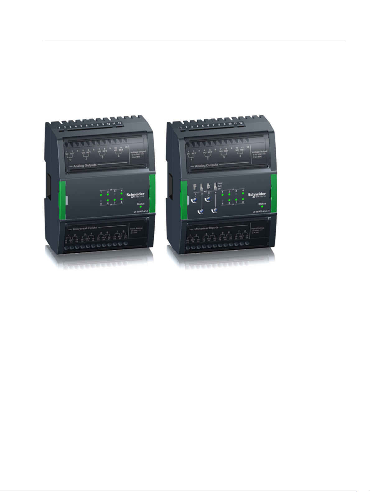
II//OO MMoodduulleess UUII--88//AAOO--VV--44 aanndd
UUII--88//AAOO--VV--44--HH
8 channel universal input and 4 channel analog voltage output
1
Introduction
The UI-8/AO-V-4 and UI-8/AO-V-4-H are universal
input, 8 channel and analog output, 4 channel I/O
modules.
The universal inputs are ideal for any mix of
temperature, pressure, flow, status points, and
similar point types in a building control system.
The universal inputs can be configured to read
several different types of inputs:
• Digital
• Counter
• Supervised
• Voltage
• Current
• Temperature
• Resistive
Schneider Electric | Building Business
Trademarks and registered trademarks are the property of their respective owners.
03-16008-02-en June 2016
As counter inputs they are commonly used in
energy metering applications. As supervised inputs
they are used for security applications where it is
critical to know whether or not a wire has been cut
or shorted. These events provide a separate
indication of alarms and trouble conditions to the
system.
The analog outputs are capable of supporting
analog voltage point types. Therefore, analog
outputs support a wide range of devices, such as
actuators.
Function
Modular and scalable system
The modules are part of a modular system that
delivers power and communications on a common
bus. Connecting modules is a one-step process:
just slide the modules together using the built-in
connectors.
© 2016 Schneider Electric. All rights reserved.
Page 2
[SmartX Controller]
SmartStruxure solution
2
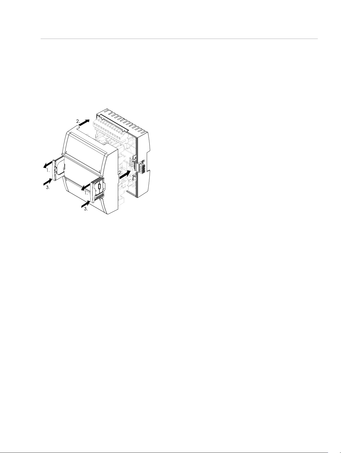
Patented two-piece design
Each module can be separated from its terminal
base to allow the site to be wired prior to the
installation of the electronics. The patented locking
mechanism serves as handles for removing the
module from its base. All critical components have
a protective cover that permits convection cooling
to occur.
Figure: Two-piece design
Hot-connect and Hot-swap
Because critical applications require 24-hour
operation, Schneider Electric designed the I/O
modules for hot-connection of terminal bases and
hot-swapping of the modules to their bases. This
design ensures continuous power and
communication during service operations.
Auto-addressing
The auto-addressing feature eliminates the need for
setting DIP switches or pressing commission
buttons. Each module automatically knows its order
in the chain and assigns itself accordingly –
significantly reducing engineering and maintenance
time.
Efficient terminal management
The I/O module terminals are clearly labeled and
protected by transparent covers. The input and
output terminals are at the top and bottom of each
module and are accessible for maintenance without
removing the module. The StruxureWare Building
Operation WorkStation software can generate
custom as-built labels for each module. Preperforated letter and A4 size label sheets are
available as an accessory.
Accommodates multiple row panel installations
The SmartStruxure devices use built-in connectors
for single row connectivity, side by side. If a panel
size requires multiple rows, extension cords are
available.
LED status indicators
The I/O module has a status indicator that denotes
the health and status of the module.
Each input channel has a dedicated two color
status LED. The LED can be configured to display
either red or green for each input state.
Hand/Off/Auto switches
The front panel of the UI-8/AO-V-4-H includes
Hand/Off/Auto (HOA) switches to provide override
control of the analog outputs.
Each output also has a potentiometer to modulate
the output signal when the switch is in the Hand
position.
The position of the HOA switch is readable through
user interfaces, such as the StruxureWare Building
Operation WorkStation software, enabling more
precise monitoring and control.
Protection
Protection components on the inputs and the
outputs protect against high-voltage short-duration
transient events.
Simple DIN-rail installation
Fasteners easily snap into a locked position for
The current inputs are protected against over
current.
panel installation. The fastener has a quick-release
feature for easy DIN-rail removal.
The analog outputs have current limits to protect
against permanent short-circuit to ground.
Specifications
Input channels ...........................................................................................................................................8
Output channels ........................................................................................................................................4
Schneider Electric | Building Business
Trademarks and registered trademarks are the property of their respective owners.
03-16008-02-en
© 2016 Schneider Electric. All rights reserved.
June 2016
Page 3

[SmartX Controller]
SmartStruxure solution
DC input supply power .......................................................................................................................1.0 W
DC input supply voltage...................................................................................................................24 VDC
Environment
Ambient temperature, operating.............................................................................0 to 50 °C (32 to 122 °F)
Ambient temperature, storage.........................................................................-20 to +70 °C (-4 to +158 °F)
Maximum humidity...............................................................................................95 % RH non-condensing
Material
Plastic rating................................................................................................................................UL94-5VB
Enclosure .......................................................................................................................................PC/ABS
Enclosure rating...................................................................................................................................IP 20
Mechanical
Dimensions including terminal base ..............................90 W x 114 H x 64 D mm (3.6 W x 4.5 H x 2.5 D in.)
3
Weight including terminal base..........................................................................................0.275 kg (0.61 lb)
Weight excluding terminal base.........................................................................................0.152 kg (0.34 lb)
Terminal base ..............................................................................................................................TB-IO-W1
Agency compliances
Emission ................................................................RCM; EN 61000-6-3; FCC Part 15, Sub-part B, Class B
Immunity ...............................................................................................................................EN 61000-6-2
Safety.................................................................................................EN 61010-1; UL 916 C-UL US Listed
Product ....................................................................................................................................EN 61326-1
Smoke control product safety...........................................................................................................UL 864
Part numbers
UI-8/AO-V-4, I/O module
8 universal inputs, 4 analog voltage outputs ....................................................................SXWUI8V4X10001
UI-8/AO-V-4-H, I/O module with HOA switches
8 universal inputs, 4 analog voltage outputs with Hand/Off/Auto override switches .........SXWUI8V4H10001
TB-IO-W1, terminal base for I/O module
(Required for each I/O module)......................................................................................SXWTBIOW110001
Accessory part numbers
DIN-RAIL-CLIP, DIN-rail end clip
package of 25 pieces ....................................................................................................SXWDINEND10001
Schneider Electric | Building Business
Trademarks and registered trademarks are the property of their respective owners.
03-16008-02-en
© 2016 Schneider Electric. All rights reserved.
June 2016
Page 4

[SmartX Controller]
SmartStruxure solution
PRINTOUT-A4-W1, printout sheets for terminal labels
A4 sheet size, 100 sheets, 18 labels per sheet...............................................................SXWTERLBL10011
PRINTOUT-LTR-W1, printout sheets for terminal labels
Letter sheet size, 100 sheets, 16 labels per sheet ..........................................................SXWTERLBL10012
S-CABLE-L, S-cable extension cord for the I/O bus, L shaped connectors
1.5 m............................................................................................................................SXWSCABLE10002
S-CABLE-L, S-cable extension cord for the I/O bus, L shaped connectors
0.75 m..........................................................................................................................SXWSCABLE10003
Universal inputs
Absolute maximum ratings .................................................................................................-0.5 to +24 VDC
A/D converter resolution....................................................................................................................12 bits
Digital
Range .........................................Dry contact switch closure or open collector/open drain, 24 VDC, 2.4 mA
Minimum pulse width .......................................................................................................................120 ms
LED polarity ...................................Software selectable, if the LED is activated when the input is high or low
LED color.................................................................................................Red or green, software selectable
Counter
Range .........................................Dry contact switch closure or open collector/open drain, 24 VDC, 2.4 mA
Minimum pulse width .........................................................................................................................20 ms
Maximum frequency ...........................................................................................................................25 Hz
LED polarity ...................................Software selectable, if the LED is activated when the input is high or low
LED color.................................................................................................Red or green, software selectable
Supervised
5 V circuit, 1 or 2 resistors
Monitored switch combinations...........................................Series only, parallel only, and series and parallel
Resistor range.........................................................................................................................1 to 10 kohm
For a 2-resistor configuration, each resistor is assumed to have the same value +/- 5 %
Voltage
Range.......................................................................................................................................0 to 10 VDC
Accuracy .........................................................................................................+/-(7 mV + 0.2 % of reading)
Resolution ........................................................................................................................................2.7 mV
Impedance...................................................................................................................................100 kohm
Reliability check .....................................................................................................................................Yes
Current
Range.........................................................................................................................................0 to 20 mA
Accuracy ....................................................................................................+/-(0.03 mA + 0.4 % of reading)
Resolution .........................................................................................................................................5.6 μA
Impedance ......................................................................................................................................47 ohm
4
Schneider Electric | Building Business
Trademarks and registered trademarks are the property of their respective owners.
03-16008-02-en
© 2016 Schneider Electric. All rights reserved.
June 2016
Page 5

[SmartX Controller]
SmartStruxure solution
Reliability check .....................................................................................................................................Yes
Resistive
10 ohm to 10 kohm accuracy.................................................................................+/-(7 + 4 x 10⁻³x R) ohm
R = Resistance in ohm
10 kohm to 60 kohm accuracy...............................................................+/-(4 x 10-3x R + 7 x 10⁻⁸x R2) ohm
R = Resistance in ohm
Reliability check .....................................................................................................................................Yes
Temperature
Range .........................................................................................................-50 to +150 °C (-58 to +302 °F)
Reliability check .....................................................................................................................................Yes
Supported thermistors
Honeywell ......................................................................................................................................20 kohm
Type I (Continuum).........................................................................................................................10 kohm
Type II (I/NET).................................................................................................................................10 kohm
Type III (Satchwell)..........................................................................................................................10 kohm
Type IV (FD)................................................................................................................................... 10 kohm
Type V (FD w/ 11k shunt)...............................................................................................Linearized 10 kohm
Satchwell D?T ...............................................................................................................Linearized 10 kohm
Johnson Controls..........................................................................................................................2.2 kohm
Xenta ............................................................................................................................................1.8 kohm
Balco ...............................................................................................................................................1 kohm
Thermistor accuracy
20 kohm, 10 kohm, 2.2 kohm, and 1.8 kohm....................-50 to -30 °C: +/-1.5 °C (-58 to -22 °F: +/-2.7 °F)
...........................................................................................-30 to 0 °C: +/-0.5 °C (-22 to +32 °F: +/-0.9 °F)
............................................................................................. 0 to 50 °C: +/-0.2 °C (32 to 122 °F: +/-0.4 °F)
....................................................................................... 50 to 100 °C: +/-0.5 °C (122 to 212 °F: +/-0.9 °F)
..................................................................................... 100 to 150 °C: +/-1.5 °C (212 to 302 °F: +/-2.7 °F)
Linearized 10 kohm ..........................................................-50 to -30 °C: +/-3.0 °C (-58 to -22 °F: +/-5.4 °F)
...........................................................................................-30 to 0 °C: +/-1.0 °C (-22 to +32 °F: +/-1.8 °F)
............................................................................................. 0 to 50 °C: +/-0.3 °C (32 to 122 °F: +/-0.5 °F)
....................................................................................... 50 to 100 °C: +/-0.5 °C (122 to 212 °F: +/-0.9 °F)
..................................................................................... 100 to 150 °C: +/-2.0 °C (212 to 302 °F: +/-3.6 °F)
1 kohm .......................................................................-50 to +150 °C: +/-1.5 °C (-58 to +302° F: +/-2.7 °F)
Analog outputs, AO
5
Voltage
Range.......................................................................................................................................0 to 10 VDC
Accuracy ....................................................................................................................................+/-100 mV
Resolution ........................................................................................................................................42 mV
Minimum load resistance ...............................................................................................................5 kohm
Schneider Electric | Building Business
Trademarks and registered trademarks are the property of their respective owners.
03-16008-02-en
© 2016 Schneider Electric. All rights reserved.
June 2016
Page 6

[SmartX Controller]
SmartStruxure solution
Load range .............................................................................................................................-1 to +2 mA
Reliability check ...................................................................................................................................Yes
6
For protection from excess current that could be
produced by field wiring, follow these instructions:
• Connect one RET terminal on each of the I/O
modules to a common chassis/power ground
rail in the control panel using a size 16 AWG,
1.3 mm, or larger wire.
Regulatory Notices
Federal Communications Commission
FCC Rules and Regulations CFR 47, Part 15, Class B
This device complies with part 15 of the FCC Rules. Operation is subject to the following
two conditions: (1) This device may not cause harmful interference. (2) This device must
accept any interference received, including interference that may cause undesired
operation.
Industry Canada
This Class B digital apparatus complies with Canadian ICES-003.
Cet appareil numérique de la classe B est conforme à la norme NMB-003 du Canada.
Regulatory Compliance Mark (RCM) - Australian Communications and Media
Authority (ACMA)
This equipment complies with the requirements of the relevant ACMA standards made
under the Radiocommunications Act 1992 and the Telecommunications Act 1997. These
standards are referenced in notices made under section 182 of the Radiocommunications
Act and 407 of the Telecommunications Act.
• Individual 24 VDC power sources to the field
must be current limited to maximum of 4
amps for UL compliant installations, and no
more than 6 amps in other areas.
• For more information on wiring, see
Hardware Reference Guide.
CE - Compliance to European Union (EU)
2014/30/EU Electromagnetic Compatibility Directive
2011/65/EU Restriction of Hazardous Substances (RoHS) Directive
This equipment complies with the rules, of the Official Journal of the European Union, for
governing the Self Declaration of the CE Marking for the European Union as specified in
the above directive(s) per the provisions of the following standards: EN 61326-1 Product
Standard, EN 61010-1 Safety Standard.
WEEE - Directive of the European Union (EU)
This equipment and its packaging carry the waste of electrical and electronic equipment
(WEEE) label, in compliance with European Union (EU) Directive 2012/19/EU, governing
the disposal and recycling of electrical and electronic equipment in the European
community.
UL 916 Listed products for the United States and Canada, Open Class Energy
Management Equipment. UL file E80146.
UL 864 Listed products for the United States. 10thEdition Smoke Control
System. UL file S5527.
Schneider Electric | Building Business
Trademarks and registered trademarks are the property of their respective owners.
03-16008-02-en
© 2016 Schneider Electric. All rights reserved.
June 2016
 Loading...