


Modicon TM5
EIO0000000889 09/2020
Modicon TM5
Safety Logic Controller SLC100/200 FS
Hardware Guide
Original instructions
09/2020
EIO0000000889.08
www.schneider-electric.com

The information provided in this documentation contains general descriptions and/or technical
characteristics of the performance of the products contained herein. This documentation is not
intended as a substitute for and is not to be used for determining suitability or reliability of these
products for specific user applications. It is the duty of any such user or integrator to perform the
appropriate and complete risk analysis, evaluation and testing of the products with respect to the
relevant specific application or use thereof. Neither Schneider Electric nor any of its affiliates or
subsidiaries shall be responsible or liable for misuse of the information contained herein. If you
have any suggestions for improvements or amendments or have found errors in this publication,
please notify us.
You agree not to reproduce, other than for your own personal, noncommercial use, all or part of
this document on any medium whatsoever without permission of Schneider Electric, given in
writing. You also agree not to establish any hypertext links to this document or its content.
Schneider Electric does not grant any right or license for the personal and noncommercial use of
the document or its content, except for a non-exclusive license to consult it on an "as is" basis, at
your own risk. All other rights are reserved.
All pertinent state, regional, and local safety regulations must be observed when installing and
using this product. For reasons of safety and to help ensure compliance with documented system
data, only the manufacturer should perform repairs to components.
When devices are used for applications with technical safety requirements, the relevant
instructions must be followed.
Failure to use Schneider Electric software or approved software with our hardware products may
result in injury, harm, or improper operating results.
Failure to observe this information can result in injury or equipment damage.
© 2020 Schneider Electric. All rights reserved.
2 EIO0000000889 09/2020

Table of Contents
Safety Information. . . . . . . . . . . . . . . . . . . . . . . . . . . . . . 5
About the Book . . . . . . . . . . . . . . . . . . . . . . . . . . . . . . . . 7
Chapter 1 Functional Safety Information. . . . . . . . . . . . . . . . . . . . . 13
IEC 61508 and Safety Integrity Level (SIL) . . . . . . . . . . . . . . . . . . . . .
Functional Safety Certification. . . . . . . . . . . . . . . . . . . . . . . . . . . . . . .
Training . . . . . . . . . . . . . . . . . . . . . . . . . . . . . . . . . . . . . . . . . . . . . . . .
Chapter 2 TM5CSLC100FS and TM5CSLC200FS . . . . . . . . . . . . . 21
General Information on Safety Logic Controllers. . . . . . . . . . . . . . . . .
Safety Logic Controller Presentation. . . . . . . . . . . . . . . . . . . . . . . . . .
Safety Logic Controller Characteristics . . . . . . . . . . . . . . . . . . . . . . . .
Safety Logic Controller Memory Key. . . . . . . . . . . . . . . . . . . . . . . . . .
Chapter 3 Operating and Connection Elements . . . . . . . . . . . . . . . 35
Safety Logic Controller Description . . . . . . . . . . . . . . . . . . . . . . . . . . .
Logic Processor LED Indicators . . . . . . . . . . . . . . . . . . . . . . . . . . . . .
Logic Processor Selection Switch and Confirmation Button . . . . . . . .
Safety Terminal Block Presentation . . . . . . . . . . . . . . . . . . . . . . . . . .
Integrated Power Supply . . . . . . . . . . . . . . . . . . . . . . . . . . . . . . . . . .
Sercos III Interface . . . . . . . . . . . . . . . . . . . . . . . . . . . . . . . . . . . . . . .
Glossary . . . . . . . . . . . . . . . . . . . . . . . . . . . . . . . . . . . . . . . . .
Index . . . . . . . . . . . . . . . . . . . . . . . . . . . . . . . . . . . . . . . . .
14
15
19
22
23
25
28
36
38
42
44
47
49
55
57
EIO0000000889 09/2020 3

4 EIO0000000889 09/2020
Safety Information
Important Information
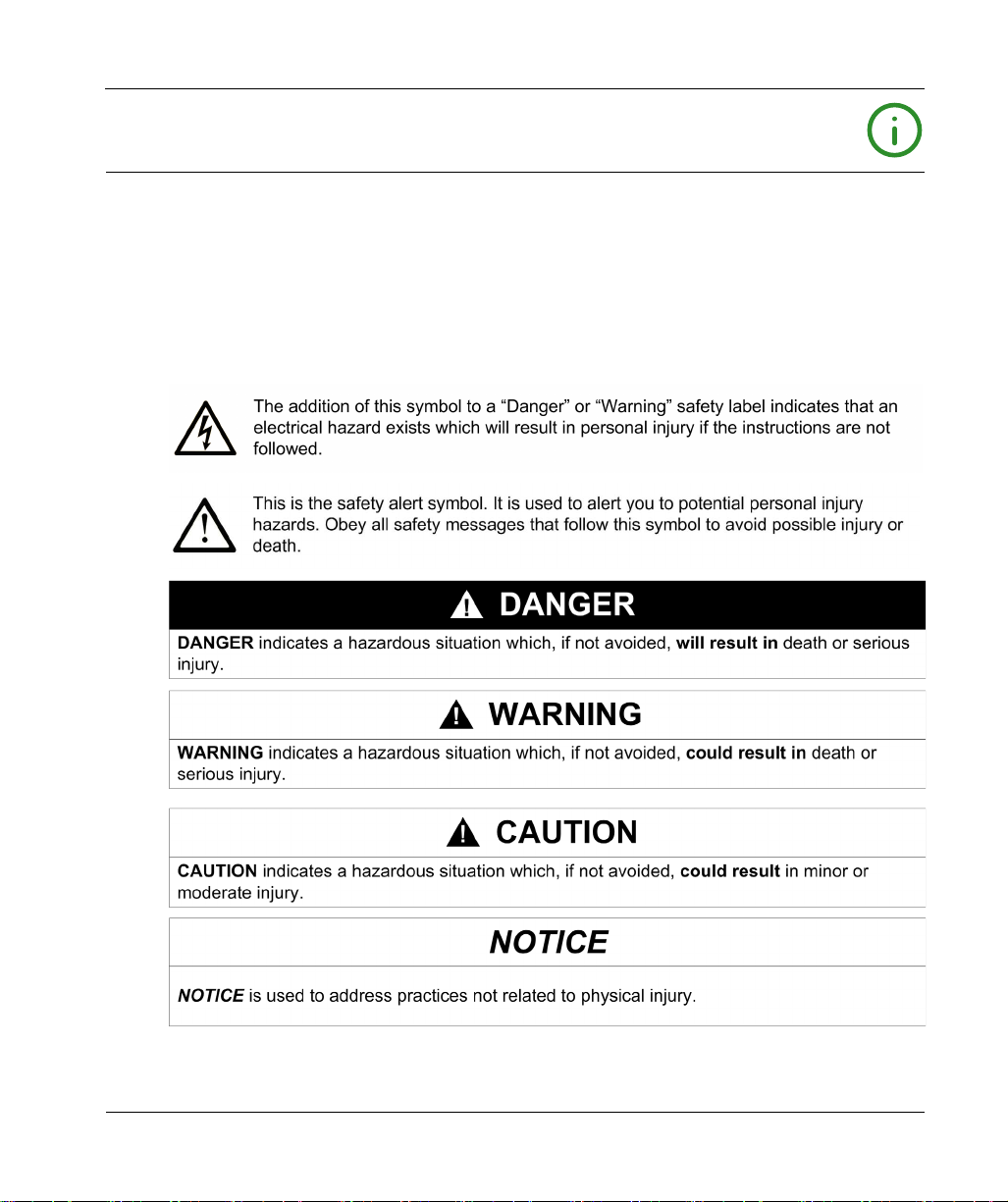
NOTICE
Read these instructions carefully, and look at the equipment to become familiar with the device
before trying to install, operate, service, or maintain it. The following special messages may appear
throughout this documentation or on the equipment to warn of potential hazards or to call attention
to information that clarifies or simplifies a procedure.
EIO0000000889 09/2020 5

PLEASE NOTE
Electrical equipment should be installed, operated, serviced, and maintained only by qualified
personnel. No responsibility is assumed by Schneider Electric for any consequences arising out of
the use of this material.
A qualified person is one who has skills and knowledge related to the construction and operation
of electrical equipment and its installation, and has received safety training to recognize and avoid
the hazards involved.
QUALIFICATION OF PERSONNEL
Only appropriately trained persons who are familiar with and understand the contents of this
manual and all other pertinent product documentation are authorized to work on and with this
product.
The qualified person must be able to detect possible hazards that may arise from parameterization,
modifying parameter values and generally from mechanical, electrical, or electronic equipment.
The qualified person must be familiar with the standards, provisions, and regulations for the
prevention of industrial accidents, which they must observe when designing and implementing the
system.
INTENDED USE
The products described or affected by this document, together with software, accessories, and
options, are programmable logic controllers (referred to herein as “logic controllers”), intended for
industrial use according to the instructions, directions, examples, and safety information contained
in the present document and other supporting documentation.
The product may only be used in compliance with all applicable safety regulations and directives,
the specified requirements, and the technical data.
Prior to using the product, you must perform a risk assessment in view of the planned application.
Based on the results, the appropriate safety-related measures must be implemented.
Since the product is used as a component in an overall machine or process, you must ensure the
safety of persons by means of the design of this overall system.
Operate the product only with the specified cables and accessories. Use only genuine accessories
and spare parts.
Any use other than the use explicitly permitted is prohibited and can result in unanticipated
hazards.
6 EIO0000000889 09/2020
About the Book
At a Glance
Document Scope
This manual describes the Safety Logic Controllers SLC100 Sercos III (TM5CSLC100FS) and
SLC200 Sercos III (TM5CSLC200FS). These controllers help you to achieve the safety
requirements codified in the IEC 61508 standard. The present document also provides part
descriptions, specifications and wiring diagrams.
Schneider Electric takes no responsibility for the solutions adopted by you or any customer
concerning the circuits, the electrical schematics, and the chosen configuration parameters of the
application. The implemented circuits and electrical diagrams and the choice of the system
configuration parameter values, including those of TM5CSLC100FS and TM5CSLC200FS, are
fully under your control and responsibility.
Validity Note
This document has been updated for the release of EcoStruxure
The technical characteristics of the devices described in the present document also appear online.
To access the information online, go to the Schneider Electric home page at
The characteristics that are described in the present document should be the same as those
characteristics that appear online. In line with our policy of constant improvement, we may revise
content over time to improve clarity and accuracy. If you see a difference between the document
and online information, use the online information as your reference.
TM
Machine Expert V1.2.5.
www.se.com
.
Related Documents
Document title Reference
Modicon TM5/TM7 I/O Safety Modules Hardware
Guide
PacDrive TM5 / TM7 Safety Flexible System, System
Planning and Installation Guide
Modicon M262 Logic/Motion Controller, Programming
Guide
EIO0000000889 09/2020 7
EIO0000000861 (ENG)
EIO0000000862 (GER)
EIO0000001064 (ENG)
EIO0000001066 (GER)
EIO0000003651 (ENG)
EIO0000003652 (FRE)
EIO0000003653 (GER)
EIO0000003654 (SPA)
EIO0000003655 (ITA)
EIO0000003656 (CHS)
EIO0000003657 (POR)
EIO0000003658 (TUR)
Document title Reference
How to Configure the Firewall for PacDrive LMC
Controllers, User Guide
EcoStruxure Machine Expert, CommonToolbox,
Library Guide
You can download these technical publications and other technical information from our website
www.schneider-electric.com/en/download
at
Product Related Information
HAZARD OF ELECTRIC SHOCK, EXPLOSION OR ARC FLASH
Disconnect all power from all equipment including connected devices prior to removing any
covers or doors, or installing or removing any accessories, hardware, cables, or wires except
under the specific conditions specified in the appropriate hardware guide for this equipment.
Always use a properly rated voltage sensing device to confirm the power is off where and when
indicated.
Replace and secure all covers, accessories, hardware, cables, and wires and confirm that a
proper ground connection exists before applying power to the unit.
Use only the specified voltage when operating this equipment and any associated products.
Failure to follow these instructions will result in death or serious injury.
EIO0000004198 (ENG)
EIO0000004199 (GER)
EIO0000004219 (ENG)
.
DANGER
DANGER
POTENTIAL FOR EXPLOSION
Only use this equipment in non-hazardous locations, or in locations that comply with Class I,
Division 2, Groups A, B, C and D.
Do not substitute components which would impair compliance to Class I, Division 2.
Do not connect or disconnect equipment unless power has been removed or the location is
known to be non-hazardous.
Do not use the USB port(s), if so equipped, unless the location is known to be non-hazardous.
Failure to follow these instructions will result in death or serious injury.
8 EIO0000000889 09/2020
WARNING
LOSS OF CONTROL
The designer of any control scheme must consider the potential failure modes of control paths
and, for certain critical control functions, provide a means to achieve a safe state during and
after a path failure. Examples of critical control functions are emergency stop and overtravel
stop, power outage and restart.
Separate or redundant control paths must be provided for critical control functions.
System control paths may include communication links. Consideration must be given to the
implications of unanticipated transmission delays or failures of the link.
Observe all accident prevention regulations and local safety guidelines.
Each implementation of this equipment must be individually and thoroughly tested for proper
1
operation before being placed into service.
Failure to follow these instructions can result in death, serious injury, or equipment damage.
1
For additional information, refer to NEMA ICS 1.1 (latest edition), "Safety Guidelines for the
Application, Installation, and Maintenance of Solid State Control" and to NEMA ICS 7.1 (latest
edition), "Safety Standards for Construction and Guide for Selection, Installation and Operation of
Adjustable-Speed Drive Systems" or their equivalent governing your particular location.
WARNING
UNINTENDED EQUIPMENT OPERATION
Only use software approved by Schneider Electric for use with this equipment.
Update your application program every time you change the physical hardware configuration.
Failure to follow these instructions can result in death, serious injury, or equipment damage.
The Safety Logic Controller system is built to the following safety integrity levels: SIL 3 according
to EN/IEC 61508, SILcl 3 according to EN/IEC 62061, in accordance with the applicable
standards. However, the definitive SIL and PL of the application depends on the number of safety
components, their parameters, and the connections that are made, as per the risk analysis.
The module must be configured in accordance with the application-specific risk analysis and all the
applicable standards.
Pay particular attention in conforming to any safety information, different electrical requirements,
and normative standards that would apply to your adaptation.
EIO0000000889 09/2020 9
UNINTENDED EQUIPMENT OPERATION
Perform an in-depth risk analysis to determine the appropriate safety integrity level for your
specific application, based on all the applicable standards.
Do not exceed SIL 3 ratings in the application of this product.
Failure to follow these instructions can result in death, serious injury, or equipment damage.
For reasons of Internet security, TCP/IP forwarding is disabled by default. Therefore, you must
manually enable TCP/IP forwarding. However, doing so may expose your network to possible
cyberattacks if you do not take additional measures to protect your enterprise. In addition, you may
be subject to laws and regulations concerning cybersecurity.
UNAUTHENTICATED ACCESS AND SUBSEQUENT NETWORK INTRUSION
Observe and respect any an all pertinent national, regional and local cybersecurity and/or
personal data laws and regulations when enabling TCP/IP forwarding on an industrial network.
Isolate your industrial network from other networks inside your company.
Protect any network against unintended access by using firewalls, VPN, or other, proven
security measures.
Failure to follow these instructions can result in death, serious injury, or equipment damage.
Terminology Derived from Standards
The technical terms, terminology, symbols and the corresponding descriptions in this manual, or
that appear in or on the products themselves, are generally derived from the terms or definitions
of international standards.
In the area of functional safety systems, drives and general automation, this may include, but is not
limited to, terms such as
safety, safety function, safe state, fault, fault reset, malfunction, failure
error, error message, dangerous
Among others, these standards include:
WARNING
WARNING
,
, etc.
Standard Description
IEC 61131-2:2007 Programmable controllers, part 2: Equipment requirements and tests.
ISO 13849-1:2015 Safety of machinery: Safety related parts of control systems.
General principles for design.
EN 61496-1:2013 Safety of machinery: Electro-sensitive protective equipment.
Part 1: General requirements and tests.
ISO 12100:2010 Safety of machinery - General principles for design - Risk assessment and risk
10 EIO0000000889 09/2020
reduction
Standard Description
EN 60204-1:2006 Safety of machinery - Electrical equipment of machines - Part 1: General
ISO 14119:2013 Safety of machinery - Interlocking devices associated with guards - Principles
ISO 13850:2015 Safety of machinery - Emergency stop - Principles for design
IEC 62061:2015 Safety of machinery - Functional safety of safety-related electrical, electronic,
IEC 61508-1:2010 Functional safety of electrical/electronic/programmable electronic safety-
IEC 61508-2:2010 Functional safety of electrical/electronic/programmable electronic safety-
IEC 61508-3:2010 Functional safety of electrical/electronic/programmable electronic safety-
IEC 61784-3:2016 Industrial communication networks - Profiles - Part 3: Functional safety
2006/42/EC Machinery Directive
2014/30/EU Electromagnetic Compatibility Directive
2014/35/EU Low Voltage Directive
requirements
for design and selection
and electronic programmable control systems
related systems: General requirements.
related systems: Requirements for electrical/electronic/programmable
electronic safety-related systems.
related systems: Software requirements.
fieldbuses - General rules and profile definitions.
In addition, terms used in the present document may tangentially be used as they are derived from
other standards such as:
Standard Description
IEC 60034 series Rotating electrical machines
IEC 61800 series Adjustable speed electrical power drive systems
IEC 61158 series Digital data communications for measurement and control – Fieldbus for use in
industrial control systems
Finally, the term
hazards, and is defined as it is for a
2006/42/EC
(
zone of operation
) and
ISO 12100:2010
may be used in conjunction with the description of specific
hazard zone
or
danger zone
in the
Machinery Directive
.
NOTE: The aforementioned standards may or may not apply to the specific products cited in the
present documentation. For more information concerning the individual standards applicable to the
products described herein, see the characteristics tables for those product references.
EIO0000000889 09/2020 11

12 EIO0000000889 09/2020
Modicon TM5
Functional Safety Informat ion
EIO0000000889 09/2020
Functional Safety Informat ion
Chapter 1
Functional Safety Information
What Is in This Chapter?
This chapter contains the following topics:
IEC 61508 and Safety Integrity Level (SIL) 14
Functional Safety Certification 15
Training 19
Topic Page
EIO0000000889 09/2020 13

Functional Safety Information
IEC 61508 and Safety Integrity Level (SIL)
Introduction
The TM5CSLC100FS and TM5CSLC200FS Safety Logic Controllers are part of a Safety-Related
System certified according to IEC 61508 by TÜV NORD.
IEC 61508 Description
The IEC 61508 is a technical standard concerning the functional safety of electrical, electronic or
programmable electronic safety-related systems.
A safety-related system is a system that is required to perform one or more specific functions to
ensure that risks are kept at or below an acceptable level. Such functions are defined as safety
functions.
A system is defined “functionally safe” when random, systematic, and common cause equipment
or machine failures do not lead to malfunctioning of the system and do not result in injury or death
of humans, spills to the environment, and loss of equipment and production.
Description of the Safety Integrity Level (SIL)
Safety-related functions are executed to help achieve and maintain the defined safe state of a
system. The IEC 61508 specifies four levels of safety performance for a safety-related function.
These are called Safety Integrity Levels (SIL), ranging from 1 (the lowest) to 4 (the highest). The
TM5CSLC100FS and TM5CSLC200FS Safety Logic Controllers are certified for use in SIL 3
applications in which the de-energized state is the defined safe state.
14
EIO0000000889 09/2020

Functional Safety Certification
Introduction
The TM5CSLC100FS and TM5CSLC200FS Safety Logic Controllers are certified
by TÜV NORD
for use in applications up to and including SIL 3 according to IEC 61508 and IEC 62061.
This certification verifies that the Safety Logic Controllers are compliant with the following
standards:
IEC 61508: Functional safety of electrical/electronic/programmable electronic safety-related
systems, Parts 1 to 4, 2010, up to SIL 3
ISO 13849-1: Safety of machinery - Safety-related parts of control systems - Part 1: General
principles for design, 2015, up to PL e (Category 4)
IEC 62061: Safety of machinery - Functional safety of safety-related electrical, electronic, and
programmable electronic control systems, 2005 (A1:2013), up to SILcl 3
NOTE: Using Safety Logic Controller equipment is a necessary but insufficient precondition for the
certification of a SIL 3 application. A SIL 3 application must also fulfill the requirements of the
IEC 61508, IEC 61511, IEC 61131-2, and other application standards.
Functional Safety Parameters
The Functional Safety parameters according to EN ISO 13849 are as follows:
Performance Level for
SDI (safety-related digital input) to SDO (safety-related digital output): up to PL e
SAI (safety-related analog input) to SAO (safety-related analog output): up to PL e
Category: up to 4
Functional Safety Information
Classification of the Schneider Electric Products
The Safety Logic Controllers are dedicated to perform safety-related functions. The Safety Logic
Controller system consist of the controller supporting the Sercos III fieldbus network. The controller
then interfaces with the Sercos III Bus Interface, TM5/TM7 Safety-Related I/O modules, and other
safety-related devices such as drives and third-party devices. However, it also supports other
modules, enabling you to add non-safety-related parts to your SIL 3 project.
Therefore, the Schneider Electric products must be distinguished into:
safety-related modules and
non-safety-related modules
In contrast to the safety-related modules, non-safety-related modules are not used to perform
safety-related functions. They are certified as non-interfering modules for use with the Safety Logic
Controller. A detected error in one of these modules does not interfere with the execution of the
safety-related functions.
EIO0000000889 09/2020 15
Functional Safety Information
Safety-Related Products of the Safety Logic Controller System
The Safety Logic Controller system is comprised of the following safety-related products:
Type Module Reference
Safety Logic Controller, SLC 100 Sercos III, 24 Vdc TM5CSLC100FS
Safety Logic Controller, SLC 200 Sercos III, 24 Vdc TM5CSLC200FS
Safety-related Module 2DI 24 Vdc Sink TM5SDI2DFS
Safety-related Module 4DI 24 Vdc Sink TM5SDI4DFS
Safety-related Module 20DI 24 Vdc Sink TM5SDI20DFS
Safety-related Module 2DO 24 Vdc, 0.5 A TM5SDO2TFS
Safety-related Module 2DO 24 Vdc, 2 A TM5SDO2TAFS
Safety-related Module 4DO 24 Vdc, 0.5 A TM5SDO4TFS
Safety-related Module 2DO TM5SDO2TRFS
Safety-related Module 4DO 24 Vdc, 2 A TM5SDO4TAFS
Safety-related Module 6DO 24 Vdc, 0.2 A TM5SDO6TBFS
Safety-related Module 2DI (2 test (pulse) outputs), 2DO 24 Vdc, 6 A TM5SDM4DTRFS
Safety-related Module 6DI, 2DO 24 Vdc TM5SDM8TBFS
Safety-related Module 2x2AI 4-20 mA 24 bits TM5SAI4AFS
Safety-related Module 2x2AI Thermocouple J/K/N/S/R/C/T TM5STI4ATCFS
Safety-related Counter Module DC1 7 kHz 24 Vdc Sink TM5SDC1FS
Safety-related Power Distribution Module PS 1DO 24 Vdc TM5SPS10FS
IP67 Block, 8 DI, 24 Vdc TM7SDI8DFS
IP67 Block, 8 DI, 4 DO, 2 A TM7SDM12DTFS
TM5 Bus Base for safety-related Electronic modules, safety coded, internal I/O
supply interconnected
Safety-related Terminal Block, 12-pin, safety coded TM5ACTB52FS
Memory Key, 8 MB
(1) A memory key is required for operation of the Safety Logic Controller, and is sold separately. For more
information concerning the role of the memory key in the Safety Logic Controller system, refer to Safety Logic
Controller Memory Key
(1)
(see page 28)
.
TM5ACBM3FS
TM5ACSLCM8FS
16
Only modules certified as safety-related modules are allowed to perform safety functions. Make
certain that neither inputs nor outputs of non-safety-related modules are used for safety-related
inputs or outputs.
EIO0000000889 09/2020

IMPROPERLY CONFIGURED SAFETY-RELATED SYSTEM
Use only safety-certified products for use in a safety-related system.
Use only Schneider Electric authorized products in a Safety Logic Controller system.
Failure to follow these instructions will result in death or serious injury.
NOTE: The Sercos III Bus Interface, required for communication with TM5 Safety-related modules,
is considered a non-interfering module and does not contribute nor detract from the safety function
of the controller. The safety layer part of the Sercos III communication is managed inside the
Safety-related modules and not in the Sercos III Bus Interface.
Available Bus Interface
The following Schneider Electric bus interface is available:
Module Type Module Reference
Sercos III Bus Interface TM5NS31
NOTE: The Sercos III Bus Interface, required for communication with the safety-related expansion
modules, is considered a non-interfering module and does not contribute nor detract from the
safety-related function of the controller. The safety layer part of the Sercos III communication is
managed inside the safety-related modules and not in the Sercos III Bus Interface.
For more information on safety-related product architectures, refer to TM5 / TM7 Safety-Related
System I/O Architecture
Installation Guide)
Functional Safety Information
DANGER
(see PacDrive TM5 / TM7 Safety Flexible System, System Planning and
.
DANGER
IMPROPER SAFETY-RELATED SYSTEM
Use only modules designated as safety-related modules to perform safety-related functions.
Make sure that neither inputs nor outputs of non-safety-related modules are used for safety-
related outputs.
Failure to follow these instructions will result in death or serious injury.
Probabilities of Failure
For SIL 3 applications, IEC 61508 defines the following probabilities of failure on demand (PFD)
and probabilities of failure per hour (PFH) depending on the mode of operation:
PFD ≥ 10
PFH ≥ 10
EIO0000000889 09/2020 17
-4
to < 10-3 for low demand mode of operation
-8
to < 10-7 for high demand mode of operation

Functional Safety Information
Defined Safe State and Life Span
For more information on the defined safe state of modules in the case of detected errors as well
as on the life span, refer to Defined Safe State and Life Span
Modules, Hardware Guide)
(see Modicon TM5/TM7, I/O Safety
.
18
EIO0000000889 09/2020

Training
Introduction
As stated in the IEC 61508, Part 1, App. B, all persons involved in a Safety Lifecycle activity must
have the appropriate training, technical knowledge, experience, and qualifications relevant apply
the products specified in the present document. Training, technical knowledge, experience, and
qualifications should be assessed in relation to each particular application.
NOTE: Make sure you possess all information and skills required to install, run, and maintain
Safety-Related Systems correctly.
Functional Safety Information
EIO0000000889 09/2020 19

Functional Safety Information
20
EIO0000000889 09/2020

Modicon TM5
SLC 100 Sercos III and SL C 200 Sercos III
EIO0000000889 09/2020
TM5CSLC100FS and TM 5CSLC200FS
Chapter 2
TM5CSLC100FS and TM5CSLC200FS
What Is in This Chapter?
This chapter contains the following topics:
General Information on Safety Logic Controllers 22
Safety Logic Controller Presentation 23
Safety Logic Controller Characteristics 25
Safety Logic Controller Memory Key 28
Topic Page
EIO0000000889 09/2020 21

SLC 100 Sercos III and SLC 200 Sercos III
General Information on Safety Logic Controllers
General Overview
Safety Logic Controllers manage the tasks within a safety-related application and provide the
following functionalities:
configuration management
parameter management
execution of the safety-related application program
NOTE: The safety-related modules must be connected through a Sercos III Bus Interface.
Configuration Management
The configuration management monitors the safety-related configuration of the application in the
Safety Logic Controller and provides the following functions:
Helps ensure a consistent, safety-related configuration.
Verifies the module types, as well as the hardware and firmware versions, with those specified
in the Safety Logic Controller application.
Verifies the configuration at startup and periodically during operation.
Parameter Management
When replacements are needed, the parameter management system helps to ensure that newly
installed modules are assigned correct parameters that apply to the application in the Safety Logic
Controller.
The parameter management provides the following functions:
Helps to ensure consistent parameters on the safety-related I/O modules.
Verifies the parameters with those specified in the Safety Logic Controller application.
Independently performs complete parameter downloads.
Memory Key
The memory key on the Safety Logic Controller supports the following features:
holds the safety-related application that is loaded at boot-up.
storage medium for the application, configuration, and parameters.
application transfer of safety-related functions to another Safety Logic Controller.
NOTE: A memory key is required for operation of the Safety Logic Controller. For more information
concerning the role of the memory key in the Safety Logic Controller system, refer to Safety Logic
Controller Memory Key
22
(see page 28)
.
EIO0000000889 09/2020

Safety Logic Controller Presentation
Features
The table below describes the features of TM5CSLC100FS and TM5CSLC200FS :
Feature TM5CSLC100FS TM5CSLC200FS
System module Safety CPU Standard Safety CPU Plus
Maximum I/O modules
via Sercos III interface
Interfaces Sercos III, controlled node, integrated 2x switch
Application memory exchangeable application memory: memory key
Dimensions (W x H x D) 87.5 x 99 x 75 mm (3.44 x 3.89 x 2.92 inches)
Ordering Information
The figure below presents TM5CSLC100FS and TM5CSLC200FS in combination with the required
accessories:
20 safety-related modules 100 safety-related modules
SLC 100 Sercos III and SLC 200 Sercos III
EIO0000000889 09/2020 23

SLC 100 Sercos III and SLC 200 Sercos III
The table below presents the references for the Safety Logic Controllers and the terminal block:
Number Reference Description Color
1 TM5CSLC100FS SLC 100 Sercos III red
TM5CSLC200FS SLC 200 Sercos III
2 TM5ACTB52FS
(see page 44)
3
(1) Included in delivery of TM5CSLC100FS/TM5CSLC200FS
TM5ACLPR10
(1)
(1)
NOTE: A memory key is required for operation of the Safety Logic Controller, and is sold
separately. For more information concerning the role of the memory key in the Safety Logic
Controller system, refer to Safety Logic Controller Memory Key
TM5 terminal block, 12-pin, safety coded red
TM5 Locking plate white
(see page 28)
.
24
EIO0000000889 09/2020

Safety Logic Controller Characteristics
Introduction
This section describes the characteristics of TM5CSLC100FS and TM5CSLC200FS:
FIRE HAZARD
Use only the correct wire sizes for the maximum current capacity of the power supplies.
Failure to follow these instructions will result in death or serious injury.
UNINTENDED EQUIPMENT OPERATION
Do not exceed any of the rated values specified in the characteristics tables.
Failure to follow these instructions can result in death, serious injury, or equipment damage.
General Characteristics
The table below provides general characteristics of TM5CSLC100FS and TM5CSLC200FS :
SLC 100 Sercos III and SLC 200 Sercos III
DANGER
WARNING
General Characteristics
Status indicators
Diagnostics Diagnostics for controller functions, Sercos III and memory key
Cooling convection
Power consumption 5.1 W
Certifications and standards
EIO0000000889 09/2020 25
Controller state
Sercos III
Memory key
are indicated by status LED.
CE
CSA, Class I., Div. 2
cULus
EN 62061
EN ISO 13849-1
IEC 61508

SLC 100 Sercos III and SLC 200 Sercos III
Operating Conditions
The table below lists the operating conditions for TM5CSLC100FS and TM5CSLC200FS:
Operating Conditions
Mounting orientation horizontal or vertical
Operating temperature horizontal installation 0...+55 °C (+32...131°F)
Relative humidity 5...95%
Installation at altitudes above sea level: Up to 2000 m (up to 6561 ft) no derating
EN 60529 Protection IP20
Storage and Transport Conditions
The table below lists the storage and transport conditions for TM5CSLC100FS and
TM5CSLC200FS:
Storage and Transport Conditions
Temperature -25...+70 °C (-13...+158 °F)
Relative humidity 5...95%
vertical installation 0...+45 °C (+32...113 °F)
> 2000 m (>6561 ft) reduction of ambient temperature
by 0.5 °C per 100 m (32.9 °F per
328 ft)
Controller Characteristics
The table below lists the controller characteristics for TM5CSLC100FS and TM5CSLC200FS:
Controller
Fastest task class cycle time 2 ms
Memory Key slot 1x
Real-time clock
Modular interface slots none
Processor Intel XSCALE 266 MHz
Fieldbus Characteristics
The table below lists the fieldbus characteristics for TM5CSLC100FS and TM5CSLC200FS:
Fieldbus
Type Sercos III
26
non-volatile memory
resolution 1 second
EIO0000000889 09/2020

Fieldbus
Design internal 2x switch
Cable length maximum 100 m (328 ft) between two stations (segment length)
Transfer rate 100 MBit/s Full Duplex
Power Supply Characteristics
The table below lists the power supply characteristics for TM5CSLC100FS and TM5CSLC200FS:
Power supply
Rated voltage + 24 V (-15% / +20%)
Reverse polarity reaction yes
Fuse integrated, cannot be exchanged
Functionality Characteristics
The table below lists the functionality characteristics for TM5CSLC100FS and TM5CSLC200FS:
Functionality TM5CSLC100FS TM5CSLC200FS
Number of supported safety-related I/O
devices
SLC 100 Sercos III and SLC 200 Sercos III
2x shielded RJ45 port
maximum 20 maximum 100
Safety-Related Characteristics
The table below lists the safety-related characteristics for TM5CSLC100FS and TM5CSLC200FS:
Characteristic Value
Category according to EN ISO 13849 CAT 4
Maximum performance level according to EN ISO 13849 PL e
Maximum safety integrity level according to IEC 62061 SIL 3
Maximum safety integrity level according to IEC 61508 SIL 3
PFH
PFD
-9
<1*10
<1*10
<2*10
-5
at a proof test interval of 10 years
-5
at a proof test interval of 20 years
PT maximum 20 years
DC >90%
SFF >90%
MTTFd >100 years
Life time
(see Modicon TM5/TM7, I/O Safety Modules,
20 years
Hardware Guide)
EIO0000000889 09/2020 27

SLC 100 Sercos III and SLC 200 Sercos III
Safety Logic Controller Memory Key
Presentation
A memory key is required for operation of the Safety Logic Controller, and is sold separately.
The table below presents the reference for the memory key:
Reference Description Color
TM5ACSLCM8FS Safety Logic Controller memory key, 8 Mb Gray and red
Functions of the Memory Key
The memory key is required to load the program, parameters and configuration into the Safety
Logic Controller when it boots up. In addition, you can use the key to store the program, the
parameters, and the system configuration and transfer the data to another Safety Logic Controller.
The memory key is equipped with a mechanical locking mechanism to help prevent removal during
operation:
Locking mechanism
Unlocked memory key: Locked memory key:
First Insertion and Confirmation of the Memory Key
Before applying power to the Safety Logic Controller for the first time, you have to insert the
memory key.
To confirm the first insertion of a memory key, proceed as follows:
Step Action Result
1 Ensure that the Safety Logic Controller is not
under power.
2 Insert the memory key in the Safety Logic
Controller and apply power to the Safety Logic
Controller.
28
-
The FW-ACKN LED illuminates.
EIO0000000889 09/2020

SLC 100 Sercos III and SLC 200 Sercos III
Step Action Result
3 Move the selection switch to SK-XCHG and
press the confirmation button.
4 Engage the mechanical locking mechanism. -
5 Open EcoStruxure Machine Expert - Safety,
connect to the Safety Logic Controller and set a
new password for the Safety Logic Controller
(refer to EcoStruxure Machine Expert - Safety
User Guide).
The ENTER LED illuminates. The memory key
insertion is confirmed.
NOTE: To allow the connection between
EcoStruxure Machine Expert - Safety and the
Safety Logic Controller via the Sercos bus,
appropriate Ethernet settings have to be
applied on the standard controller. Refer to the
M262 Programming Guide
Services
(see Modicon M262 Logic/Motion Controller,
Programming Guide)
refer to the User Guide
Firewall for PacDrive LMC Controllers
(see How to Configure the Firewall for
PacDrive LMC Controllers, User Guide)
CommonToolbox Library Guide
(see EcoStruxure Machine Expert,
CommonToolbox, Library Guide)
information on related IEC application
functions.
6 Download your valid safety-related application
on the Safety Logic Controller (refer to
EcoStruxure Machine Expert - Safety User
Guide).
7 Execute a complete validation of the Safety
Logic Controller functional safety system.
-
-
, chapter
for information on IP forwarding
settings. For PacDrive,
Ethernet
How to Configure the
provides
. The
WARNING
UNINTENDED EQUIPMENT OPERATION
Ensure that the Safety Logic Controller is stopped before attempting to insert or remove the
memory key.
Each time the memory key is used (inserted/replaced), carefully verify that the loaded safety
application is the one that was intended for the particular system.
Conduct a complete functional test of the system, composed of the Safety Logic Controller
plus all input and output hardware connected to it, after using the memory key to overwrite your
safety-related application.
Failure to follow these instructions can result in death, serious injury, or equipment damage.
EIO0000000889 09/2020 29

SLC 100 Sercos III and SLC 200 Sercos III
NOTE: You can verify your safety-related application by examining the project CRC and the date
that were saved with the application on the memory key. For more information, refer to the
EcoStruxure Machine Expert - Safety User Guide.
Removing a Memory Key
Removing a memory key results in a boot status change (the LED indicators F, I and L illuminate)
and a disabling of the safety-related functions. In addition, removing the memory key during
operation can corrupt the data on the memory key.
INTERRUPTION OF SAFETY-RELATED FUNCTION AND POSSIBLE LOSS OF MEMORY
KEY DATA
Do not remove the memory key when the Safety Logic Controller is in a RUN state.
Engage the locking mechanism while the key is inserted in the Safety Logic Controller.
Failure to follow these instructions can result in death, serious injury, or equipment damage.
To remove the memory key, proceed as follows:
Step Action
1 Ensure that the Safety Logic Controller is STOPPED or that power has been removed.
2 Disengage the mechanical locking mechanism.
3 Pull the memory key out of the Safety Logic Controller.
NOTE: The Safety Logic Controller requires a valid memory key to operate.
WARNING
Copying to a Memory Key
Copying to a memory key is a function that allows you to copy the configuration data from the
Safety Logic Controller to another memory key. The application and parameters are not copied to
the memory key.
Pre-requisite 1: The Safety Logic Controller is operational, therefore, with an existing memory key.
Pre-requisite 2: You have another memory key, already containing an application valid for the
present Safety Logic Controller.
30
EIO0000000889 09/2020

SLC 100 Sercos III and SLC 200 Sercos III
To transfer the configuration data to another memory key, proceed as follows:
Step Action Result/Comment
1 Set the selection switch to SK-COPY position
and press the confirmation button.
NOTE: Refer to Logic Processor Selection
Switch and Confirmation Button
(see page 42)
2 Dis-engage the mechanical locking
mechanism and replace the existing memory
key by the other memory key.
.
(1)
NOTE: Do not move the selection switch. It
remains on the position SK-COPY.
3
Press the confirmation button
4 Move the selection switch to SK-XCHG and
press the confirmation button.
5 Engage the mechanical locking mechanism. 6 Execute a complete validation of the Safety
Logic Controller functional safety system.
(1) If no memory key is inserted after 30 seconds, the Safety Logic Controller switches to boot status (the
LED indicators F, I and L illuminate).
(2) If the other memory key is not acknowledged after 30 seconds, the function ends, that is, in case the
function is triggered inadvertently, the copy function ends automatically after 30 seconds.
(2)
.
Result: The ENTER LED illuminates and the
SKEY LED flashes. The existing memory key
configuration data is saved to an internal,
temporary file on the Safety Logic Controller to
be later transferred to the other memory key, and
the FW-ACKN LED flashes when the action is
completed.
A maximum of 30-second delay is provided for
this step. The FW-ACKN LED flash frequency
increases after 20 seconds to signal the end of
that delay.
The internal, temporarily saved configuration file
is transferred to the memory key.
Result: The ENTER LED illuminates. The
memory key replacement is confirmed
(see page 32)
-
.
WARNING
UNINTENDED EQUIPMENT OPERATION
Ensure that the Safety Logic Controller is stopped before attempting to insert or remove the
memory key.
Each time the memory key is used (inserted/replaced), carefully verify that the loaded safety
application is the one that was intended for the particular system.
Conduct a complete functional test of the system, composed of the Safety Logic Controller
plus all input and output hardware connected to it, after using the memory key to overwrite your
safety-related application.
Failure to follow these instructions can result in death, serious injury, or equipment damage.
EIO0000000889 09/2020 31

SLC 100 Sercos III and SLC 200 Sercos III
NOTE: You can verify your safety-related application by examining the project CRC and the date
that were saved with the application on the memory key. For more information, refer to the
EcoStruxure Machine Expert - Safety User Guide.
Confirming Memory Key Insertion
The following procedure authorizes the safety-related application stored on the memory key to be
used with the Safety Logic Controller. In addition, after confirmation, the application on the memory
key is compared with that in execution memory, and if they are different, the application on the
memory key is transferred to the Safety Logic Controller.
To confirm the insertion of a memory key, proceed as follows:
Step Action Result
1 Ensure that the Safety Logic Controller is
STOPPED.
2 Insert the memory key in the Safety Logic
Controller.
NOTE: The Safety Logic Controller requires a
valid memory key to operate.
3 Move the selection switch to SK-XCHG and
press the confirmation button.
4 Engage the mechanical locking mechanism. -
5 Execute a complete validation of the Safety
Logic Controller functional safety system.
-
The FW-ACKN LED illuminates.
The ENTER LED illuminates. The memory key
replacement is confirmed
-
(see page 32)
.
32
WARNING
UNINTENDED EQUIPMENT OPERATION
Ensure that the Safety Logic Controller is stopped before attempting to insert or remove the
memory key.
Each time the memory key is used (inserted/replaced), carefully verify that the loaded safety
application is the one that was intended for the particular system.
Conduct a complete functional test of the system, composed of the Safety Logic Controller
plus all input and output hardware connected to it, after using the memory key to overwrite your
safety-related application.
Failure to follow these instructions can result in death, serious injury, or equipment damage.
NOTE: You can verify your safety-related application by examining the project CRC and the date
that were saved with the application on the memory key. For more information, refer to the
EcoStruxure Machine Expert - Safety User Guide.
EIO0000000889 09/2020

Creating a Memory Key Backup
The procedure described in Copying to a Memory Key
memory key backup by using a second memory key with an identical safety-related application.
After executing the procedures, two identical memory keys are available.
Formatting the Memory Key
The following procedure allows you to format the memory key. Only use this procedure if your
firmware update was not successful or the memory has a detected error.
A formatting of the memory key deletes the current memory key data, including your password.
LOSS OF MEMORY KEY DATA
Create a memory key backup before formatting the memory key.
Connect to the EcoStruxure Machine Expert - Safety software to assign a new password.
Failure to follow these instructions can result in equipment damage.
To format the memory key, proceed as follows:
Step Action Comment / Result
1 Ensure that the Safety Logic Controller is
stopped.
2 Move the selection switch to the unlabeled
position between SK-XCHG and FW-ACKN.
(see page 30)
NOTICE
SLC 100 Sercos III and SLC 200 Sercos III
can also be used to create a
-
3 Press the confirmation button for a minimum of
20 to 30 s to receive a confirmation.
EIO0000000889 09/2020 33
After 20 s, the ENTER LED illuminates.
NOTE:
When you have released the confirmation
button, the ENTER LED remains illuminated
for another second.
When you press the confirmation button for
less than 20 s, it has no effect.
When you press the confirmation button for
longer than 30 s, the ENTER LED flashes
for 5 s to display a detected error.
Result: The LED will indicate that there is no
valid application on the key

SLC 100 Sercos III and SLC 200 Sercos III
Step Action Comment / Result
4 Follow the procedures necessary to add a valid
application to the key.
-
34
EIO0000000889 09/2020

Modicon TM5
Operating and Connectio n Elements
EIO0000000889 09/2020
Operating and Connectio n Elements
Chapter 3
Operating and Connection Elements
Information
This chapter provides information on operating and connection elements, as well as the LED
indicators of the Safety Logic Controller.
What Is in This Chapter?
This chapter contains the following topics:
Safety Logic Controller Description 36
Logic Processor LED Indicators 38
Logic Processor Selection Switch and Confirmation Button 42
Safety Terminal Block Presentation 44
Integrated Power Supply 47
Sercos III Interface 49
Topic Page
EIO0000000889 09/2020 35

Operating and Connection Elements
Safety Logic Controller Description
Description
The LED indicators, buttons and switches are integrated to operate the Safety Logic Controller.
The following figure presents the operating and connection elements:
36
N° Description Refer to
1 Confirmation button Confirming a Function
2 Selection switch Description of the Selection Switch Functions
(see page 43)
(see page 42)
3 Logic processor Logic Processor LED indicators
4 Sercos III interface Sercos III interface
5 Integrated power supply Integrated Power Supply
6 Sercos address switches Sercos Address
7 Terminal block for Safety Logic Controller
power supply
Safety-Related Terminal Block Presentation
(see page 44)
(see page 49)
(see page 51)
(see page 38)
(see page 47)
EIO0000000889 09/2020

Operating and Connection Elements
N° Description Refer to
8 Sercos III connection with 2 x RJ45 Sercos III RJ45 Ports
9 Memory key slot / slot cover Safety Logic Controller Memory Key
(seepage52)
(see page 28)
These components enable you to perform the following operations:
module replacement
firmware update
memory key replacement, including a possible transfer of module configuration from the
previous memory key
support for the replacement of Safety Logic Controller
EIO0000000889 09/2020 37

Operating and Connection Elements
Logic Processor LED Indicators
Description of the LED Indicators for the Logic Processor
The figure and table present the LED indicators for the logic processor of the TM5CSLC100FS and
TM5CSLC200FS:
LED
indicator
R/E N/A off Boot phase -
ENTER
(1) When a module scan is being executed, the ENTER, MXCHG, and FW-ACKN LED indicators are flashing.
(2) When the controller is in error state, the states of the other L ED indicator s ( R/E, ENTER, MXCHG, and FW-ACKN)
are not updated.
LED color LED status Description Instructions / information for
the user
green on Application found and executed
flashing Application exists but is not being
processed
orange on EcoStruxure Machine Expert -
Safety software is in RUN
(Debug) state
flashing EcoStruxure Machine Expert -
fast flashing No application found on the
(1)
green on Waiting for confirmation -
1x flash every 0.8 s Confirmation of correct entry
flashes (1 Hz) for 5sOperator error detected
Safety software is in STOP
(Debug) state or HALT (Debug)
state, application stopped
memory key
38
EIO0000000889 09/2020

Operating and Connection Elements
LED
indicator
MXCHG
LED color LED status Description Instructions / information for
the user
(1)
orange off Valid module configuration -
Replacement of one module
detected
Select the position 1 on the
selection switch and press the
confirmation button ENTER.
Replacement of two modules
detected
Select the position 2 on the
selection switch and press the
confirmation button ENTER.
Replacement of three modules
detected
Select the position 3 on the
selection switch and press the
confirmation button ENTER.
Replacement of four modules
detected
Select the position 4 on the
selection switch and press the
confirmation button ENTER.
Replacement of more than four
modules detected
Select the position n on the
selection switch and press the
confirmation button ENTER.
Missing module detected -
FWACKN
orange off Valid firmware configuration -
(1)
flashing Firmware update successful Select the position FW-ACKN
on the selection switch and
press the confirmation button
ENTER.
on Memory key was exchanged Select the position SK-XCHG
on the selection switch and
press the confirmation button
ENTER.
(1) When a module scan is being executed, the ENTER, MXCHG, and FW-ACKN LED indicators are flashing.
(2) When the controller is in error state, the states of the other LED ind ica tor s (R/E, ENTER, MXCHG, and FW-ACKN)
are not updated.
EIO0000000889 09/2020 39

Operating and Connection Elements
LED
indicator
F
A
I
L
LED color LED status Description Instructions / information for
the user
red FAI LThese four LEDs indicate first the
boot status, then, when the
system is running, the general
state of the controller.
x- xx
Boot phase
Loading of the firmware
Memory key is missing
Project CRC (Cyclic
Redundancy Check) is wrong
or not defined
Safety Logic Controller cycle
time is exceeded
If the LED status persists:
Refer to the Safe logger for
additional diagnostic
information on the error.
Verify if the memory key is
plugged correctly.
Re-download the
corresponding project, and
verify the project CRC.
Verify the cycle time and
increase it if necessary.
x x x x Hardware test (max. approx. 5 s) -
x X x X Initialization and start-up of the
firmware
---X Pre-operational state
- - - - Operational state
xxxx
Controller in error state
(2)
x = illuminated
X= brightly illuminated
- = off
alternating flashing
of FI and AL
EcoStruxure Machine Expert Safety software is connected and
in RUN (Debug) state
SKEY orange off No access to the memory key -
flashing Access to the memory key
(1) When a module scan is being executed, the ENTER, MXCHG, and FW-ACKN LED indicators are flashing.
(2) When the controller is in error state, the states of the other L ED indicator s ( R/E, ENTER, MXCHG, and FW-ACKN)
are not updated.
Testing the LED Indicators for the Logic Processor
Follow this procedure to test the LED indicators:
Step Action
1 Position the selection switch to TEST.
40
EIO0000000889 09/2020

Step Action
2 Press the confirmation button.
Result: All LED indicators on the logic processor illuminates for as long as you press the
confirmation button.
Operating and Connection Elements
EIO0000000889 09/2020 41

Operating and Connection Elements
Logic Processor Selection Switch and Confirmation Button
Overview
Whenever you make a change in the configuration (module or memory key replacement, or
firmware update), you need to acknowledge the change on the Safety Logic Controller using the
selection switch and the confirmation button.
The following figure presents the selection switch and the confirmation button:
Description of the Selection Switch Functions
The following table describes the selectable functions:
Selection switch position Function Description
FW-ACKN Firmware update To acknowledge the firmware update on one or more
modules
SK-XCHG Memory key replacement
To confirm the memory key replacement
(see page 30)
SK-COPY Memory key copy
To copy of the configuration data from the memory key
(see page 30)
SCAN Scan To perform a module scan
TEST Test
1, 2, 3, 4, n Module(s) replacement To confirm the replacement of 1, 2, 3, 4 or more than 4
(1) Triggers an automatic restart.
(see page 40)
To perform a LED indicator test
module(s)
(1)
(1)
(1)
42
EIO0000000889 09/2020

Confirming a Function
To confirm a configuration change, proceed as follows:
Step Action
1 Select the desired function by means of the selection switch.
NOTE: If you do not place the selection switch properly, the LED ENTER flashes for 5 s to
display a detected error.
Example: To replace one specific module, place the selection switch on 1. If the selection switch
is not set to 1 when only one module was replaced, an error is detected and the LED ENTER
flashes for 5 s.
2 Press the confirmation button for 0.5 to 5 s to receive a confirmation.
Result: After 0.5 s, the LED ENTER is illuminated.
3 Release the confirmation button.
Result: The LED ENTER remains illuminated for additional 0.8 s.
NOTE: If you release the confirmation button before 0.5 s, it has no effect. If you press the confirmation
button longer than 5 s, the LED ENTER flashes for 5 s to display a detected error.
Operating and Connection Elements
EIO0000000889 09/2020 43

Operating and Connection Elements
Safety Terminal Block Presentation
TM5ACTB52FS Features
The safety-related modules and the Safety Logic Controllers are wired by means of the
TM5ACTB52FS Safety terminal block:
Features
Type of terminal block 12-pin, safety coded terminal block
Features
Ordering Information
The following figure presents the TM5ACTB52FS Safety terminal block:
tool-free wiring with push-in technology
simple wire release using lever
allows labeling of each terminal
allows plain text labeling
test access for standard probes
potential for customer coding
44
The following table presents the reference for the Safety terminal block:
Reference Description Color
TM5ACTB52FS 24 Vdc / 230 Vac, 12-pin terminal block for
safety-related modules and Safety Logic
Controllers, safety coded
red
EIO0000000889 09/2020

INCOMPATIBLE COMPONENTS CAUSE ELECTRIC SHOCK OR ARC FLASH
Do not associate components of a slice that have different colors.
Verify that correct terminal blocks (minimally, matching colors and correct number of
terminals) are installed on the appropriate electronic modules.
Failure to follow these instructions will result in death or serious injury.
Characteristics
This section describes the characteristics of the TM5ACTB52FS Safety terminal block, you can
also refer to TM5 Environmental Characteristics
Hardware Guide)
FIRE HAZARD
Use only the correct wire sizes for the maximum current capacity of the I/O channels and
power supplies.
For relay output (2 A) wiring, use conductors of at least 0.5 mm
rating of at least 80 °C (176 °F).
For common conductors of relay output wiring (4 A), or relay output wiring greater than 2 A,
use conductors of at least 1.0 mm
(176 °F).
Failure to follow these instructions will result in death or serious injury.
Operating and Connection Elements
DANGER
(see Modicon TM5/TM7, I/O Safety Modules,
.
DANGER
2
(AWG 20) with a temperature
2
(AWG 16) with a temperature rating of at least 80 °C
WARNING
UNINTENDED EQUIPMENT OPERATION
Do not connect wires to unused terminals and/or terminals indicated as “No Connection (N.C.)”.
Failure to follow these instructions can result in death, serious injury, or equipment damage.
WARNING
UNINTENDED EQUIPMENT OPERATION
Do not exceed any of the rated values specified in the characteristics tables.
Failure to follow these instructions can result in death, serious injury, or equipment damage.
EIO0000000889 09/2020 45

Operating and Connection Elements
The following table lists the characteristics of the TM5ACTB52FS:
Characteristics
Type of terminal block Push-in terminal block
Distance between
contacts
Contact resistance ≤ 5 mΩ
Maximum current carrying capacity of the
connector
Connection cross
section
Cable type Copper wires only
LOOSE WIRING CAUSES ELECTRIC SHOCK
Do not insert more than one wire per connector of the spring terminal blocks unless using a
double wire cable end (ferrule).
Failure to follow these instructions will result in death or serious injury.
left - right 4.2 mm / 0.16 in
above - below 10.96 mm / 0.43 in
10 A / contact
NOTE: The electrical characteristics of the individual
modules must be respected.
solid wire
multi-wire
with wire cable ends
-
0.08 mm
0.25 mm
0.25 mm2 ... 1.5 mm2 / AWG 24 ... 16
Up to 2x 0.75 mm
wire cable ends
2
... 2.5 mm2 / AWG 28 ... 14
2
... 2.5 mm2/ AWG 24 ... 14
DANGER
2
(AWG 2 x 24 ... 2 x 18) with double
46
EIO0000000889 09/2020

Integrated Power Supply
Presentation
A power supply is integrated in the Safety Logic Controller TM5CSLC100FS and TM5CSLC200FS.
LED indicators
The following figure presents the status LED indicators for integrated power supply:
The following table describes the LED status for the integrated power supply:
LED indicator LED color LED status State description
DCOK green on Power applied to the controller
Operating and Connection Elements
off No power applied to the controller
Wiring Diagram
DANGER
FIRE HAZARD
Use only the correct wire sizes for the maximum current capacity of the power supplies.
Failure to follow these instructions will result in death or serious injury.
DANGER
HAZARD OF ELECTRIC SHOCK, EXPLOSION, OVERHEATING AND FIRE
Do not connect the modules directly to line voltage.
Use only isolating PELV systems according to IEC 61140 to supply power to the modules.
Connect the 0 Vdc of the external power supplies to FE (Functional Earth/ground).
Failure to follow these instructions will result in death or serious injury.
EIO0000000889 09/2020 47

Operating and Connection Elements
The following figure presents the wiring diagram of the power supply for the Safety Logic
Controller:
1 Internal electronics
2 PS1: External isolated power supply 24 Vdc (-15% / +20%)
3 External fuse, Type T slow-blow, 1 A, 250 V
48
EIO0000000889 09/2020

Sercos III Interface
LED Indicators for the Sercos III Interface
The following figure presents the LED indicators for the Sercos III interface of the TM5CSLC100FS
and TM5CSLC200FS:
The following LED indicators are provided:
State
S3
S3 P1
S3 P2
Operating and Connection Elements
State LED Indicator
The State LED is a green (status) / red (error) dual LED indicator:
The following table describes the State LED indicator:
LED color LED status State description
- off No supply voltage applied or device is inoperable.
green on No detected error, bus interface is initialized and ready for operation.
green flashing (12.5 Hz) Initialization phase (booting of the I/O modules or setting up the I/O
green flashing (4 Hz) Recoverable error detected, such as missing I/O module (this LED
green flashing (0.66 Hz) New or modified configuration data (I/O modules or bus interface) have
red flashing (8 Hz) Unrecoverable error detected (for example, lack of resources, error
functional groups).
indicator is reset when the error state is corrected).
been received but not yet stored in the flash memory.
detected in the firmware data flow).
NOTE: After applying power to the bus interface, several red flashing signals are displayed. These
signals are not error indications, but indication of the initialization process.
EIO0000000889 09/2020 49

Operating and Connection Elements
NOTE: If the firmware update is unsuccessful (corrupted file, interruption of the update, etc.), the
bus interface restarts with the previous version of the firmware.
S3 (Sercos III) LED Indicator
The following table describes the S3 LED indicator:
LED color LED status State description Instructions
- off Power is removed or there is no
green on Active Sercos III connection without
green flashing (4 Hz,
125 ms)
red on Sercos III diagnostic class error has
red/green flashing (4 Hz,
125 ms)
(1) IdentifyDevice is a parameter in EcoStruxure Machine Expert.
communication due to a connection
interruption.
a detected error in the
Communication Phase 4 (CP4).
The device is in Loopback mode.
Loopback describes the situation in
which the Sercos III telegrams have
to be sent back on the same port on
which they were received.
Possible causes:
line topology
Sercos III ring break
been detected on port 1 and/or
Sercos III communication is no
longer possible on the ports (for
example due to an encoder error).
Detected communication error.
Possible causes:
improper functioning of the
telegram
detected CRC (Cyclic
Redundancy Check) error
Apply power or verify physical
connections
n.a.
Close the ring.
Reset condition
clear the detected device
errors
acknowledge the detected
error in the menu
switch from CP2 to CP3
alternatively.
NOTE: Diagnostic
messages pending in the
system are not
acknowledged by this.
Reset condition
The configuration indicates
the detected error
acknowledge the detected
error.
switch from CP2 to CP3
alternatively.
NOTE: Diagnostic
messages pending in the
system are not
acknowledged by this.
50
EIO0000000889 09/2020

LED color LED status State description Instructions
orange on The device is in a communication
orange flashing (4 Hz,
125 ms)
(1) IdentifyDevice is a parameter in EcoStruxure Machine Expert.
S3 P1/S3 P2 LED Indicators
The following table describes the S3 P1 (Port 1) and S3 P2 (Port 2) LED indicators:
LED color LED status State description
- off no cable connected
green flashing active Sercos III communication
green on link, but no telegrams / communication (for example controller is
Sercos Address
The Sercos address is set by two switches. Positioning the switches at 0 triggers the autoaddressing feature.
NOTE: Only Sercos addresses between 1 and 255 are allowed.
The following figure presents the Sercos address switches:
Operating and Connection Elements
n.a.
phase CP0 up to and including CP3.
Sercos III telegrams are received.
Device identification Triggered by using the
parameter IdentifyDevice
or the DriveAssistant tool.
booting)
(1)
NOTE: The Sercos address is in hexadecimal notation. Set the address (1...255 dec) manually by
the two Sercos address switches.
EIO0000000889 09/2020 51

Operating and Connection Elements
The following table describes the Sercos address, set with the 2 hexadecimal switches:
Sercos address Description
0 dec (0 hex) Auto-addressing (not a valid address)
1-255 dec (1-FF hex) Manual addressing
(1) IdentificationMode is a parameter in EcoStruxure Machine Expert.
Example:
In order to set the Sercos address 190 (dec) / BE (hex), set the two hexadecimal switches as
follows:
Switch x1 = E
Switch x16 = B
For PacDrive LMC controllers, the setting 0 is recognized when the
value SerialNumberController or TopologyAddress or
ApplicationType is selected for the parameter
(1)
IdentificationMode
For Modicon TM262M• controllers, the setting 0 is recognized, when
.
the value Topology mode is selected for the parameter
IdentificationMode
For PacDrive LMC controllers, this setting is recognized when the
(1)
.
value SercosAddress is selected for the parameter
IdentificationMode
For Modicon TM262M• controllers, this setting is recognized when
(1)
.
the value Sercos mode is selected for the parameter
IdentificationMode
(1)
.
Sercos III Ports
The following figure presents the RJ45 connectors of the Safety Logic Controller:
1 Sercos III PORT A (P1)
2 Sercos III PORT B (P2)
52
EIO0000000889 09/2020

Operating and Connection Elements
The following table lists the pin assignments for the RJ45 connectors:
Pin Assignment
1 RXD (Receive Data)
2RXD\
3 TXD (Transmit Data)
4 Termination
5 Termination
6TXD\
7 Termination
8 Termination
For more information about the Sercos III ports, refer to Fieldbus Characteristics
(see page 26)
.
EIO0000000889 09/2020 53

Operating and Connection Elements
54
EIO0000000889 09/2020

bus base
DC
Modicon TM5
Glossary
EIO0000000889 09/2020
Glossary
B
A bus base is a mounting device that is designed to seat an electronic module on a DIN rail and
connect it to the TM5 bus for Safe Logic Controllers. Each bus base extends the TM5 data and the
power buses and the 24 Vdc I/O power segment. The electronic modules are added to the TM5
system through their insertion on the base bus. The bus base also supplies the articulation point
for the terminal blocks.
D
diagnostic coverage
Fractional decrease in the probability of dangerous hardware failures resulting from the operation
of the automatic diagnostic tests
(definition IEC 61508)
The fraction of the possible dangerous failures λ
diagnostics and failures which remain undetected.
λ
D=λDD+λDU
The diagnostic coverage (DC) defines the fraction of the dangerous failures which are detected.
• DC
λ
DD=λD
• (1-DC)
λ
DU=λD
The definition may also be represented in terms of the following equation, where DC is the
diagnostic coverage, λ
is the probability of detected dangerous failures and λD total is the
DD
probability of total dangerous failures:
is divided into failures which are detected by
D
M
MTTFd
mean time to failure - dangerous
EIO0000000889 09/2020 55

Glossary
PFD
PFH
P
probability of failure on demand
(definition IEC 61508)
For a single channel system the average probability of a failure on demand is calculated as follows:
For a dual channel system the average probability of a failure on demand is calculated as follows:
For a dual channel system, also the Common Cause effect (CC) must be considered. The common
cause effect ranges from 1% to 10% of PFD
probability of dangerous failure per hour
(definition IEC 61508)
and PFD
CH1
(=1/RRF).
CH2
PT
SFF
56
proof test interval
S
safe failure fraction
EIO0000000889 09/2020

Modicon TM5
Index
EIO0000000889 09/2020
Index
C
certification
TM5ACBM3FS,
characteristics
TM5ACBM3FS,
TM5CSLC100FS,
TM5CSLC200FS,
confirmation button
TM5CSLC100FS,
TM5CSLC200FS,
connection elements
TM5CSLC200FS,
connection elements
TM5CSLC100FS,
44
44
25
25
42
42
36
36
I
IEC 61508
defined safe state,
Emergency Shutdown (ESD),
ESD (Emergency Shutdown),
Safety Integrity Level (SIL),
SIL (Safety Integrity Level),
IEC61508
functional safety,
integrated power supply
TM5CSLC100FS,
TM5CSLC200FS,
intended use,
6
14
14
47
47
14
14
14
14
M
memory key
TM5ACSLCM2FS,
TM5ACSLCM8FS,
memory key
TM5ACSLCM2FS,
TM5ACSLCM8FS,
23
23
28
28
O
operating conditions
TM5ACBM3FS,
operating elements
TM5CSLC200FS,
operating elements
TM5CSLC100FS,
ordering information
TM5CSLC100FS,
TM5CSLC200FS,
44
36
36
23
23
P
PFD (probability of failure on demand,
PFH (probability of failure per hour),
power consumption
TM5ACBM3FS,
probability of failure on demand (PFD),
probability of failure per hour (PFH),
44
17
17
17
17
L
LED
TM5CSLC100FS,
LED indicators
TM5CSLC100FS,
TM5CSLC200FS, 23,
EIO0000000889 09/2020 57
38
23
38
qualification of personnel,
S
selection switch
TM5CSLC200FS,
selection switch
TM5CSLC100FS,
42
42
6
Q

Index
Sercos III interface
TM5CSLC200FS,
Sercos III interface switch
TM5CSLC100FS,
storage conditions
TM5ACBM3FS,
49
49
44
T
TM5ACTB52FS,
safety terminal block,
transport conditions
TM5ACBM3FS,
23
44
44
58
EIO0000000889 09/2020
 Loading...