

ModiconTM5
EIO0000003173 09/2020
Modicon TM5
PCI Modules
Hardware Guide
09/2020
EIO0000003173.00
www.schneider-electric.com

The information provided in this documentation contains general descriptions and/or technical
characteristics of the performance of the products contained herein. This documentation is not
intended as a substitute for and is not to be used for determining suitability or reliability of these
products for specific user applications. It is the duty of any such user or integrator to perform the
appropriate and complete risk analysis, evaluation and testing of the products with respect to the
relevant specific application or use thereof. Neither Schneider Electric nor any of its affiliates or
subsidiaries shall be responsible or liable for misuse of the information contained herein. If you
have any suggestions for improvements or amendments or have found errors in this publication,
please notify us.
You agree not to reproduce, other than for your own personal, noncommercial use, all or part of
this document on any medium whatsoever without permission of Schneider Electric, given in
writing. You also agree not to establish any hypertext links to this document or its content.
Schneider Electric does not grant any right or license for the personal and noncommercial use of
the document or its content, except for a non-exclusive license to consult it on an "as is" basis, at
your own risk. All other rights are reserved.
All pertinent state, regional, and local safety regulations must be observed when installing and
using this product. For reasons of safety and to help ensure compliance with documented system
data, only the manufacturer should perform repairs to components.
When devices are used for applications with technical safety requirements, the relevant
instructions must be followed.
Failure to use Schneider Electric software or approved software with our hardware products may
result in injury, harm, or improper operating results.
Failure to observe this information can result in injury or equipment damage.
© 2020 Schneider Electric. All rights reserved.
2 EIO0000003173 09/2020

Table of Contents
Safety Information. . . . . . . . . . . . . . . . . . . . . . . . . . . . . . 5
About the Book . . . . . . . . . . . . . . . . . . . . . . . . . . . . . . . . 7
Chapter 1 TM5 System General Rules for Implementing . . . . . . . . 13
Installation and Maintenance Requirements . . . . . . . . . . . . . . . . . . . .
Wiring Rules and Recommendations . . . . . . . . . . . . . . . . . . . . . . . . .
Environmental Characteristics. . . . . . . . . . . . . . . . . . . . . . . . . . . . . . .
PCI Modules Installation . . . . . . . . . . . . . . . . . . . . . . . . . . . . . . . . . . .
Chapter 2 TM5 System PCI General Overview. . . . . . . . . . . . . . . . 25
General Description. . . . . . . . . . . . . . . . . . . . . . . . . . . . . . . . . . . . . . .
Chapter 3 TM5PCRS2 PCI Communication Electronic Module . . . 27
TM5PCRS2 Presentation . . . . . . . . . . . . . . . . . . . . . . . . . . . . . . . . . .
TM5PCRS2 Characteristics. . . . . . . . . . . . . . . . . . . . . . . . . . . . . . . . .
TM5PCRS2 Wiring Diagram . . . . . . . . . . . . . . . . . . . . . . . . . . . . . . . .
Chapter 4 TM5PCRS4 PCI Communication Electronic Module . . . 33
TM5PCRS4 Presentation . . . . . . . . . . . . . . . . . . . . . . . . . . . . . . . . . .
TM5PCRS4 Characteristics. . . . . . . . . . . . . . . . . . . . . . . . . . . . . . . . .
TM5PCRS4 Wiring Diagram . . . . . . . . . . . . . . . . . . . . . . . . . . . . . . . .
Chapter 5 TM5PCDPS PCI Communication Electronic Module . . . 39
TM5PCDPS Presentation . . . . . . . . . . . . . . . . . . . . . . . . . . . . . . . . . .
TM5PCDPS Characteristics . . . . . . . . . . . . . . . . . . . . . . . . . . . . . . . .
TM5PCDPS Wiring Diagram . . . . . . . . . . . . . . . . . . . . . . . . . . . . . . . .
Glossary . . . . . . . . . . . . . . . . . . . . . . . . . . . . . . . . . . . . . . . . .
Index . . . . . . . . . . . . . . . . . . . . . . . . . . . . . . . . . . . . . . . . .
14
17
18
20
25
28
30
31
34
36
37
40
42
43
45
49
EIO0000003173 09/2020 3

4 EIO0000003173 09/2020
Safety Information
Important Information
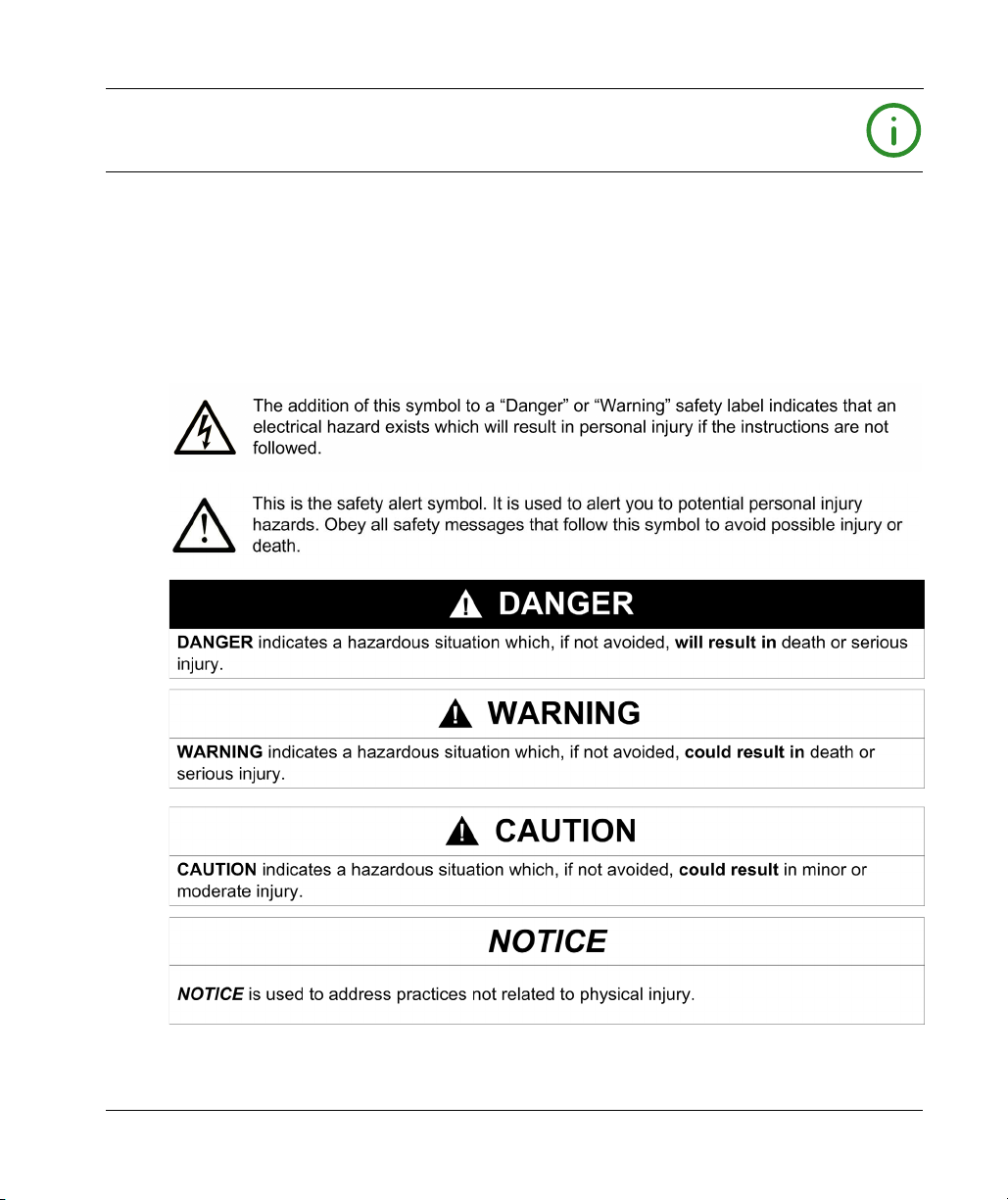
NOTICE
Read these instructions carefully, and look at the equipment to become familiar with the device
before trying to install, operate, service, or maintain it. The following special messages may appear
throughout this documentation or on the equipment to warn of potential hazards or to call attention
to information that clarifies or simplifies a procedure.
EIO0000003173 09/2020 5

PLEASE NOTE
Electrical equipment should be installed, operated, serviced, and maintained only by qualified
personnel. No responsibility is assumed by Schneider Electric for any consequences arising out of
the use of this material.
A qualified person is one who has skills and knowledge related to the construction and operation
of electrical equipment and its installation, and has received safety training to recognize and avoid
the hazards involved.
6 EIO0000003173 09/2020
About the Book
At a Glance
Document Scope
This manual describes the hardware implementation of the Modicon TM5 PCI modules. It provides
parts descriptions, specifications, wiring diagrams, installation and setup for
Modicon TM5 PCI modules.
Validity Note
This document has been updated for the release of EcoStruxureTM Machine Expert V1.2.5.
The technical characteristics of the devices described in the present document also appear online.
To access the information online, go to the Schneider Electric home page
https://www.se.com/ww/en/download/
The characteristics that are described in the present document should be the same as those
characteristics that appear online. In line with our policy of constant improvement, we may revise
content over time to improve clarity and accuracy. If you see a difference between the document
and online information, use the online information as your reference.
Related Documents
Title of Documentation Reference Number
Modicon TM5 Expansion Modules Configuration Programming
Guide
Modicon Flexible TM5 / TM7 System - System Planning and
Installation Guide
Modicon TM5 PCI Modules Instruction Sheet
.
EIO0000003179 (Eng)
EIO0000003180 (Fre)
EIO0000003181 (Ger)
EIO0000003182 (Spa)
EIO0000003183 (Ita)
EIO0000003184 (Chs)
EIO0000003161 (Eng)
EIO0000003162 (Fre)
EIO0000003163 (Ger)
EIO0000003164 (Spa)
EIO0000003165 (Ita)
EIO0000003166 (Chs)
BBV56042
You can download these technical publications and other technical information from our website
at https://www.se.com/ww/en/download/ .
EIO0000003173 09/2020 7
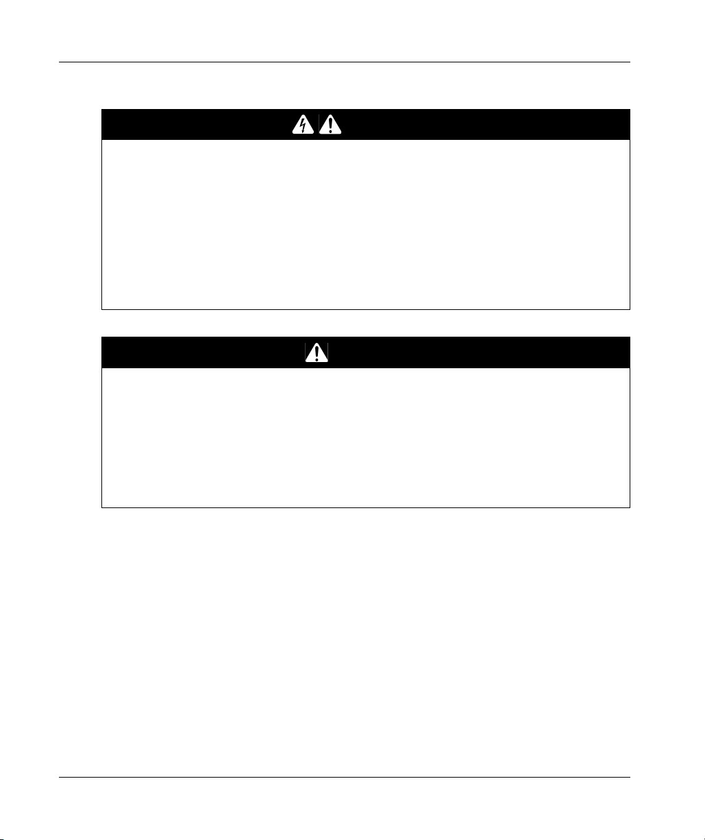
Product Related Information
HAZARD OF ELECTRIC SHOCK, EXPLOSION OR ARC FLASH
Disconnect all power from all equipment including connected devices prior to removing any
covers or doors, or installing or removing any accessories, hardware, cables, or wires except
under the specific conditions specified in the appropriate hardware guide for this equipment.
Always use a properly rated voltage sensing device to confirm the power is off where and when
indicated.
Replace and secure all covers, accessories, hardware, cables, and wires and confirm that a
proper ground connection exists before applying power to the unit.
Use only the specified voltage when operating this equipment and any associated products.
Failure to follow these instructions will result in death or serious injury.
POTENTIAL FOR EXPLOSION
Only use this equipment in non-hazardous locations, or in locations that comply with Class I,
Division 2, Groups A, B, C and D.
Do not substitute components which would impair compliance to Class I, Division 2.
Do not connect or disconnect equipment unless power has been removed or the location is
known to be non-hazardous.
Do not use the USB port(s), if so equipped, unless the location is known to be non-hazardous.
Failure to follow these instructions will result in death or serious injury.
DANGER
DANGER
8 EIO0000003173 09/2020
WARNING
LOSS OF CONTROL
The designer of any control scheme must consider the potential failure modes of control paths
and, for certain critical control functions, provide a means to achieve a safe state during and
after a path failure. Examples of critical control functions are emergency stop and overtravel
stop, power outage and restart.
Separate or redundant control paths must be provided for critical control functions.
System control paths may include communication links. Consideration must be given to the
implications of unanticipated transmission delays or failures of the link.
Observe all accident prevention regulations and local safety guidelines.
Each implementation of this equipment must be individually and thoroughly tested for proper
1
operation before being placed into service.
Failure to follow these instructions can result in death, serious injury, or equipment damage.
1
For additional information, refer to NEMA ICS 1.1 (latest edition), "Safety Guidelines for the
Application, Installation, and Maintenance of Solid State Control" and to NEMA ICS 7.1 (latest
edition), "Safety Standards for Construction and Guide for Selection, Installation and Operation of
Adjustable-Speed Drive Systems" or their equivalent governing your particular location.
WARNING
UNINTENDED EQUIPMENT OPERATION
Only use software approved by Schneider Electric for use with this equipment.
Update your application program every time you change the physical hardware configuration.
Failure to follow these instructions can result in death, serious injury, or equipment damage.
EIO0000003173 09/2020 9

Terminology Derived from Standards
The technical terms, terminology, symbols and the corresponding descriptions in this manual, or
that appear in or on the products themselves, are generally derived from the terms or definitions
of international standards.
In the area of functional safety systems, drives and general automation, this may include, but is not
limited to, terms such as
safety, safety function, safe state, fault, fault reset, malfunction, failure
error, error message, dangerous
Among others, these standards include:
Standard Description
IEC 61131-2:2007 Programmable controllers, part 2: Equipment requirements and tests.
ISO 13849-1:2015 Safety of machinery: Safety related parts of control systems.
EN 61496-1:2013 Safety of machinery: Electro-sensitive protective equipment.
ISO 12100:2010 Safety of machinery - General principles for design - Risk assessment and risk
EN 60204-1:2006 Safety of machinery - Electrical equipment of machines - Part 1: General
ISO 14119:2013 Safety of machinery - Interlocking devices associated with guards - Principles
ISO 13850:2015 Safety of machinery - Emergency stop - Principles for design
IEC 62061:2015 Safety of machinery - Functional safety of safety-related electrical, electronic,
IEC 61508-1:2010 Functional safety of electrical/electronic/programmable electronic safety-
IEC 61508-2:2010 Functional safety of electrical/electronic/programmable electronic safety-
IEC 61508-3:2010 Functional safety of electrical/electronic/programmable electronic safety-
IEC 61784-3:2016 Industrial communication networks - Profiles - Part 3: Functional safety
2006/42/EC Machinery Directive
2014/30/EU Electromagnetic Compatibility Directive
2014/35/EU Low Voltage Directive
General principles for design.
Part 1: General requirements and tests.
reduction
requirements
for design and selection
and electronic programmable control systems
related systems: General requirements.
related systems: Requirements for electrical/electronic/programmable
electronic safety-related systems.
related systems: Software requirements.
fieldbuses - General rules and profile definitions.
,
, etc.
10 EIO0000003173 09/2020
In addition, terms used in the present document may tangentially be used as they are derived from
other standards such as:
Standard Description
IEC 60034 series Rotating electrical machines
IEC 61800 series Adjustable speed electrical power drive systems
IEC 61158 series Digital data communications for measurement and control – Fieldbus for use in
industrial control systems
Finally, the term
hazards, and is defined as it is for a
2006/42/EC
(
zone of operation
) and
ISO 12100:2010
may be used in conjunction with the description of specific
hazard zone
or
danger zone
in the
Machinery Directive
.
NOTE: The aforementioned standards may or may not apply to the specific products cited in the
present documentation. For more information concerning the individual standards applicable to the
products described herein, see the characteristics tables for those product references.
EIO0000003173 09/2020 11

12 EIO0000003173 09/2020
ModiconTM5
TM5 System General Rules for Implementing
EIO0000003173 09/2020
TM5 System General Rules for Implementing
Chapter 1
TM5 System General Rules for Implementing
What Is in This Chapter?
This chapter contains the following topics:
Installation and Maintenance Requirements 14
Wiring Rules and Recommendations 17
Environmental Characteristics 18
PCI Modules Installation 20
Topic Page
EIO0000003173 09/2020 13
TM5 System General Rules for Implementing
Installation and Maintenance Requirements
Before Starting
Read and understand this chapter before beginning the installation of your TM5 System.
The use and application of the information contained herein require expertise in the design and
programming of automated control systems. Only you, the user, machine builder or integrator, can
be aware of all the conditions and factors present during installation and setup, operation, and
maintenance of the machine or process, and can therefore determine the automation and
associated equipment and the related safeties and interlocks which can be effectively and properly
used. When selecting automation and control equipment, and any other related equipment or
software, for a particular application, you must also consider any applicable local, regional or
national standards and/or regulations.
Pay particular attention in conforming to any safety information, different electrical requirements,
and normative standards that would apply to your machine or process in the use of this equipment.
NOTICE
ELECTROSTATIC DISCHARGE
Store all components in their protective packaging until immediately before assembly.
Never touch exposed conductive parts such as contacts or terminals.
Failure to follow these instructions can result in equipment damage.
Disconnecting Power
All options and modules should be assembled and installed before installing the control system on
a mounting rail, onto a mounting plate or in a panel. Remove the control system from its mounting
rail, mounting plate or panel before disassembling the equipment.
HAZARD OF ELECTRIC SHOCK, EXPLOSION OR ARC FLASH
Disconnect all power from all equipment including connected devices prior to removing any
covers or doors, or installing or removing any accessories, hardware, cables, or wires except
under the specific conditions specified in the appropriate hardware guide for this equipment.
Always use a properly rated voltage sensing device to confirm the power is off where and when
indicated.
Replace and secure all covers, accessories, hardware, cables, and wires and confirm that a
proper ground connection exists before applying power to the unit.
Use only the specified voltage when operating this equipment and any associated products.
Failure to follow these instructions will result in death or serious injury.
14
DANGER
EIO0000003173 09/2020
Programming Considerations
UNINTENDED EQUIPMENT OPERATION
Only use software approved by Schneider Electric for use with this equipment.
Update your application program every time you change the physical hardware configuration.
Failure to follow these instructions can result in death, serious injury, or equipment damage.
Operating Environment
UNINTENDED EQUIPMENT OPERATION
Install and operate this equipment according to the conditions described in the Environmental
Characteristics.
Failure to follow these instructions can result in death, serious injury, or equipment damage.
NOTE: Individual I/O modules may differ in terms of operating temperature de-ratings or other
important environmental characteristics. For the specific information, refer to the hardware guide
for your particular module.
TM5 System General Rules for Implementing
WARNING
WARNING
EIO0000003173 09/2020 15

TM5 System General Rules for Implementing
Installation Considerations
UNINTENDED EQUIPMENT OPERATION
Use appropriate safety interlocks where personnel and/or equipment hazards exist.
Install and operate this equipment in an enclosure appropriately rated for its intended
environment and secured by a keyed or tooled locking mechanism.
Use the sensor and actuator power supplies only for supplying power to the sensors or
actuators connected to the module.
Power line and output circuits must be wired and fused in compliance with local and national
regulatory requirements for the rated current and voltage of the particular equipment.
Do not use this equipment in safety-critical machine functions unless the equipment is
otherwise designated as functional safety equipment and conforming to applicable regulations
and standards.
Do not disassemble, repair, or modify this equipment.
Do not connect any wiring to reserved, unused connections, or to connections designated as
No Connection (N.C.).
Failure to follow these instructions can result in death, serious injury, or equipment damage.
NOTE: JDYX2 or JDYX8 fuse types are UL-recognized and CSA approved.
WARNING
16
EIO0000003173 09/2020
Wiring Rules and Recommendations
Introduction
There are several rules that must be followed when wiring PCI module.
Wiring Rules
HAZARD OF ELECTRIC SHOCK, EXPLOSION OR ARC FLASH
Disconnect all power from all equipment including connected devices prior to removing any
covers or doors, or installing or removing any accessories, hardware, cables, or wires except
under the specific conditions specified in the appropriate hardware guide for this equipment.
Always use a properly rated voltage sensing device to confirm the power is off where and when
indicated.
Replace and secure all covers, accessories, hardware, cables, and wires and confirm that a
proper ground connection exists before applying power to the unit.
Use only the specified voltage when operating this equipment and any associated products.
Failure to follow these instructions will result in death or serious injury.
The following rules must be applied when wiring the PCI module:
Use twisted-pair, shielded cables for networks and field bus.
Refer to the section Grounding the TM5 System
System Planning and Installation Guide)
TM5 System General Rules for Implementing
DANGER
(see Modicon TM5 / TM7 Flexible System,
to ground the shielded cables.
EIO0000003173 09/2020 17

TM5 System General Rules for Implementing
Environmental Characteristics
Enclosure Requirements
TM5 components are designed as Zone B, Class A industrial equipment according to IEC/CISPR
Publication 11. If they are used in environments other than those described in the standard, or in
environments that do not meet the specifications in this manual, your ability to meet
electromagnetic compatibility requirements in the presence of conducted and/or radiated
interference may be reduced.
The TM5 components meet European Community (CE) requirements for open equipment as
defined by EN61131-2. You must install them in an enclosure designed for the specific
environmental conditions and to minimize the possibility of unintended contact with hazardous
voltages. Your enclosure should be constructed of metal to improve the electromagnetic immunity
of your TM5 System. Your enclosure should have a keyed locking mechanism to minimize
unauthorized access.
Environmental Characteristics
This equipment meets UL, CSA, GOST-R and c-Tick certifications and CE requirements as
indicated in the table below. This equipment is intended for use in a Pollution Degree 2 industrial
environment.
The table below provides the general environmental characteristics:
Characteristic Specification
This product is compliant with Europe RoHS recommendations and China RoHS regulations.
Standard IEC61131-2 ed. 3 2007
Agencies UL 508
CSA 22.2 No. 142-M1987
CSA 22.2 No. 213-M1987
Ambient operating
temperature
Storage temperature -25...70°C (-13...158 °F)
Relative humidity 5...95% (non-condensing)
Degree of pollution IEC60664 2
Degree of
protection
Corrosion immunity No
Operating altitude 0...2000 m (0...6.560 ft.)
Storage altitude 0...3000 m (0...9.842 ft.)
Horizontal installation
Vertical installation 0...50 °C (32...122 °F)
IEC61131-2 IP20
0...55 °C (32...131 °F)
1
18
EIO0000003173 09/2020
Characteristic Specification
Vibration
Mounted on a DIN rail 3.5 mm (0.138 in.) fixed amplitude from
resistance
Mechanical shock resistance
Connection type Removable spring terminal block
Connector insertion/removal cycles 50
Note:
1 Some devices have extended temperature operating ranges subject to derating and
possibly other restrictions. See the specific characteristics for your electronic module.
Electromagnetic Susceptibility
The table below provides the TM5 System electromagnetic susceptibility specifications:
Characteristic Specification Range
Electrostatic
discharge
Electromagnetic
fields
Fast transients burst IEC/EN 61000-4-4 Power lines: 2 kV
Surge immunity
24 Vdc circuit
Surge immunity
230 Vac circuit
Induced
electromagnetic field
Conducted emission EN 55011 (IEC/CISPR11) 150...500 kHz, quasi peak 79 dBµV
Radiated emission EN 55011 (IEC/CISPR11) 30...230 MHz, 10 m@40 dBµV/m
TM5 System General Rules for Implementing
5...8.4 Hz
2
9.8 m/s
(1 gn) fixed acceleration from
8.4...150 Hz
2
147 m/s
(15 gn) for a duration of 11 ms
IEC/EN 61000-4-2 8 kV (air discharge)
4 kV (contact discharge)
IEC/EN 61000-4-3 10 V/m (80 MHz...2 GHz)
1 V/m (2...2.7 GHz)
I/O: 1 kV
Shielded cable: 1 kV
Repetition rate: 5 and 100 KHz
IEC/EN 61000-4-5 1 kV in common mode
0.5 kV in differential mode
2 kV in common mode
1 kV in differential mode
IEC/EN 61000-4-6 10 V
(0.15...80 MHz)
eff
500 kHz...30 MHz, quasi peak
73 dBµV
230 MHz...1 GHz, 10 m@47 dBµV/m
EIO0000003173 09/2020 19

TM5 System General Rules for Implementing
PCI Modules Installation
Installation Considerations
For mounting positions and minimum clearances, the PCI modules are mounted according to the
rules defined for the controllers. Refer to the site requirements for the installation of the system
(see Modicon TM5 / TM7 Flexible System, System Planning and Installation Guide)
NOTE: The PCI module is designed to operate within the same temperature range as the
controllers, including the controller de-rating for extended temperature operation, and temperature
restrictions associated with the mounting positions.
ELECTROSTATIC DISCHARGE
Verify that empty PCI slots have their covers in place before applying power to the controller.
Do not touch an exposed PCI connector.
Failure to follow these instructions can result in equipment damage.
ELECTROSTATIC DISCHARGE
Store electronic components in their protective packaging until immediately before assembly.
Only touch modules on the housing.
Take the necessary protective measures against electrostatic discharges.
Failure to follow these instructions can result in equipment damage.
.
NOTICE
NOTICE
20
EIO0000003173 09/2020

Installation
The following table describes the different steps to install PCI modules on the controller.
Step Action
1 Disconnect all power from all equipment prior to removing any covers or
2 Remove the PCI module from the packaging.
3 Remove the cover of the slot on the controller.
TM5 System General Rules for Implementing
installing a PCI module.
NOTE: Keep the cover to reuse it for the deinstallation.
4 Place the PCI module on the slot of the controller.
EIO0000003173 09/2020 21

TM5 System General Rules for Implementing
Step Action
5 Push the PCI module into the controller until it clicks.
De-installation
The following table describes the different steps to de-install PCI modules from the controller.
Step Action
1 Disconnect all power from all equipment, including connected devices, prior to
2 Press the locking clip on the PCI module.
removing a PCI module.
22
EIO0000003173 09/2020

Step Action
3 Pull the PCI module out from its mounting slot.
4 Put the cover on the slot of the controller.
TM5 System General Rules for Implementing
EIO0000003173 09/2020 23

TM5 System General Rules for Implementing
24
EIO0000003173 09/2020

ModiconTM5
TM5 System PCI General Overview
EIO0000003173 09/2020
TM5 System PCI General Overview
Chapter 2
TM5 System PCI General Overview
General Description
Introduction
The communication electronic modules are designed to be connected to the Modicon M258 Logic
Controller and Modicon LMC058 Motion Controller ranges.
Communication Electronic Module Features
The following table shows the communication electronic module features:
Reference Description
TM5PCRS2
(see page 28)
TM5PCRS4
(see page 34)
TM5PCDPS
(see page 39)
TM5 interface electronic module, 1 RS232, electrically isolated
TM5 interface electronic module, 1 RS485, electrically isolated
TM5 interface electronic module, Profibus DP slave
NOTE:
For information on compatibility rules between PCI communication electronic modules and
controllers, refer to:
Modicon M258 Logic Controller Hardware Guide
Hardware Guide)
Modicon LMC058 Motion Controller Hardware Guide
Hardware Guide)
EIO0000003173 09/2020 25
,
.
(see Modicon M258, Logic Controller,
(see Modicon LMC058, Motion Controller,

TM5 System PCI General Overview
PCI slots
The figure below shows a controller with the PCI slots:
NOTE: For more information on the compatibility of the PCI electronic modules with the specific
Controller references and other considerations, please see the specific Hardware Guide for your
Controller.
ELECTROSTATIC DISCHARGE
Verify that empty PCI slots have their covers in place before applying power to the controller.
Do not touch an exposed PCI connector.
Failure to follow these instructions can result in equipment damage.
NOTICE
26
For more details about addition of one more module, refer to Inserting the electronic Modules
(see Modicon TM5 / TM7 Flexible System, System Planning and Installation Guide)
.
EIO0000003173 09/2020

ModiconTM5
TM5PCRS2 PCI Communication Electronic Module
EIO0000003173 09/2020
TM5PCRS2 PCI Communication Electronic Module
Chapter 3
TM5PCRS2 PCI Communication Electronic Module
What Is in This Chapter?
This chapter contains the following topics:
TM5PCRS2 Presentation 28
TM5PCRS2 Characteristics 30
TM5PCRS2 Wiring Diagram 31
Topic Page
EIO0000003173 09/2020 27

TM5PCRS2 PCI Communication Electronic Module
PCRS2
Status
RxD
TxD
TM5PCRS2 Presentation
Main Characteristics
The table below describes the main characteristics of the serial line TM5PCRS2 communication
electronic module:
Main Characteristics
Interface type RS232
Connector type D-Sub 9, male
Transfer rate 115.2 kbit/s max.
Ordering Information
The figure below presents the TM5PCRS2:
28
EIO0000003173 09/2020

Status LEDs
STATUS
RxD
TxD
PCRS2
The figure below shows the TM5PCRS2 status LEDs:
The table below shows the description of the TM5PCRS2 status LEDs:
LED Color Status Description
Status Green On Module configured and operational.
RxD Yellow On The module is receiving data via the RS232
TxD Yellow On The module is transmitting data via the RS232
TM5PCRS2 PCI Communication Electronic Module
Red On The module is waiting for configuration.
interface.
interface.
EIO0000003173 09/2020 29

TM5PCRS2 PCI Communication Electronic Module
TM5PCRS2 Characteristics
Introduction
These are the general characteristics for the TM5PCRS2 communication electronic module. See
also the Environmental Characteristics
UNINTENDED EQUIPMENT OPERATION
Do not exceed any of the rated values specified in the environmental and electrical characteristics
tables.
Failure to follow these instructions can result in death, serious injury, or equipment damage.
General Characteristics
The table below describes the general characteristics of the TM5PCRS2 communication electronic
module:
General characteristics
Power dissipation 0.33 W max.
Weight 50 g (1.8 oz)
(see page 18)
.
WARNING
Characteristics
The table below describes the characteristics of the TM5PCRS2 communication electronic
module:
Characteristics
Isolation Between serial line
Data formats Please refer to
Handshake lines RTS, CTS
1
The two power circuits reference the same futional ground (FE) through specific components
designed to reduce effects of electromagnetic interference. These components are rated at 30 or
60 Vdc.
30
and internal
electronics
See note
Configuration, Programming Guide
1
Modicon TM5, PCI Modules
.
EIO0000003173 09/2020

TM5PCRS2 Wiring Diagram
RS232 Interface
The following diagram shows the male RS232 interface for TM5PCRS2:
TM5PCRS2 PCI Communication Electronic Module
6
9
1
5
The following table describes the different pins of the male RS232:
Pin RS232 Description
1 Reserved -
2 RxD Receives data
3 TxD Transmits data
4 Reserved -
50V -
6 Reserved -
7 RTS Ready To Send
8 CTS Clear To Send
9 Reserved -
EIO0000003173 09/2020 31

TM5PCRS2 PCI Communication Electronic Module
32
EIO0000003173 09/2020

ModiconTM5
TM5PCRS4 PCI Communication Electronic Module
EIO0000003173 09/2020
TM5PCRS4 PCI Communication Electronic Module
Chapter 4
TM5PCRS4 PCI Communication Electronic Module
What Is in This Chapter?
This chapter contains the following topics:
TM5PCRS4 Presentation 34
TM5PCRS4 Characteristics 36
TM5PCRS4 Wiring Diagram 37
Topic Page
EIO0000003173 09/2020 33

TM5PCRS4 PCI Communication Electronic Module
TM5PCRS4 Presentation
Main Characteristics
The table below describes the main characteristics of the serial line TM5PCRS4 communication
electronic module:
Main Characteristics
Interface type RS485
Connector type D-Sub 9, female
Transfer rate 115.2 kbit/s max.
Ordering Information
The figure below presents the TM5PCRS4:
Status
RxD
TxD
PCRS4
34
EIO0000003173 09/2020

Status LEDs
STATUS
RxD
TxD
PCRS4
This figure shows the TM5PCRS4 status LEDs :
The table below shows the description of the TM5PCRS4 status LEDs:
LEDs Color Status Description
Status Green On Module configured and operational.
RxD Yellow On The module is receiving data via the RS485
TxD Yellow On The module is transmitting data via the RS485
TM5PCRS4 PCI Communication Electronic Module
Red On The module is waiting for configuration.
interface.
interface.
EIO0000003173 09/2020 35

TM5PCRS4 PCI Communication Electronic Module
TM5PCRS4 Characteristics
Introduction
These are the general characteristics for the TM5PCRS4 communication electronic module. See
also Environmental Characteristics.
UNINTENDED EQUIPMENT OPERATION
Do not exceed any of the rated values specified in the environmental and electrical characteristics
tables.
Failure to follow these instructions can result in death, serious injury, or equipment damage.
General Characteristics
The table below describes the general characteristics of the TM5PCRS4 communication electronic
module:
General characteristics
Power dissipation 0.40 W max.
Weight 50 g (1.8 oz)
(see page 18)
WARNING
Characteristics
The table below describes the characteristics of the TM5PCRS4 communication electronic
module:
Characteristics
Isolation Between serial line
1
The two power circuits reference the same functional ground (FE) through specific components
designed to reduce effects of electromagnetic interference. These components are rated at 30 or
60 Vdc.
36
and internal
See note
electronics
Between channels Not isolated
1
EIO0000003173 09/2020

TM5PCRS4 Wiring Diagram
RS485 Interface
The following diagram shows the female RS485 interface for TM5PCRS4:
The following table describes the different pins of the female RS485:
Pin RS485 Description
1 Reserved -
2 Reserved -
3 D1 (A+) Transmit/receive data Low
4 Reserved -
5 0 V TTL supply
6 +5 V / 50 mA TTL supply
7 Reserved -
8 D0 (B-) Transmit/receive data High
9 Reserved -
TM5PCRS4 PCI Communication Electronic Module
EIO0000003173 09/2020 37

TM5PCRS4 PCI Communication Electronic Module
38
EIO0000003173 09/2020
ModiconTM5
TM5PCDPS PCI Communication Electronic Module
EIO0000003173 09/2020
TM5PCDPS PCI Communication Electronic Module
Chapter 5
TM5PCDPS PCI Communication Electronic Module
What Is in This Chapter?
This chapter contains the following topics:
TM5PCDPS Presentation 40
TM5PCDPS Characteristics 42
TM5PCDPS Wiring Diagram 43
Topic Page
EIO0000003173 09/2020 39

TM5PCDPS PCI Communication Electronic Module
TM5PCDPS Presentation
Main Characteristics
The table describes the main characteristics of the Profibus DP TM5PCDPS communication
electronic module:
Main Characteristics
Fieldbus Profibus DP slave
Interface type RS485
Connector type D-Sub 9, female
Transfer rate 12 Mbit/s max.
Ordering Information
The figure presents the TM5PCDPS:
40
EIO0000003173 09/2020
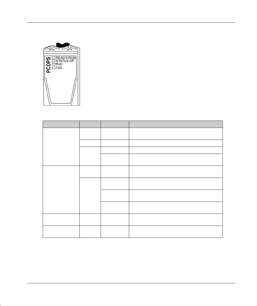
Status LEDs
This figure shows the TM5PCDPS status LEDs:
The table shows the description of the TM5PCDPS status LEDs:
LEDs Color Status Description
READY/RUN Green /
STATUS DP Green On The module is in RUN mode, performing cyclic
RxD Yellow On The module is receiving data via the RS485
TxD Yellow On The module is transmitting data via the RS485
TM5PCDPS PCI Communication Electronic Module
red
Green On Communication is performed on the PCI bus.
Red Flashing A boot error has been detected.
Red On The configuration between the slave and master is
Off The module supply is not connected.
On Communication on the PCI bus has not yet been
started.
communication.
different.
Cyclic
Flashing
Acyclic
Flashing
The module is in STOP mode, no communication is
performed, a connection error has been detected.
The module is not configured.
interface.
interface.
EIO0000003173 09/2020 41

TM5PCDPS PCI Communication Electronic Module
TM5PCDPS Characteristics
Introduction
These are the general characteristics for the TM5PCDPS communication electronic module. See
also Environmental Characteristics
UNINTENDED EQUIPMENT OPERATION
Do not exceed any of the rated values specified in the environmental and electrical characteristics
tables.
Failure to follow these instructions can result in death, serious injury, or equipment damage.
General Characteristics
The table describes the general characteristics of the TM5PCDPS communication electronic
module:
General Characteristics
Power dissipation 1.8 W
Weight 50 g (1.8 oz)
(see page 18)
.
WARNING
Characteristics
The table describes the characteristics of the TM5PCDPS communication electronic module:
Characteristics
Isolation Between Profibus DP and internal
1
The two power circuits reference the same functional ground (FE) through specific components
designed to reduce effects of electromagnetic interference. These components are rated at 30 or
60 Vdc.
42
electronics
See note
Between channels Not isolated
1
EIO0000003173 09/2020

TM5PCDPS Wiring Diagram
RS485 Interface
The diagram shows the female RS485 Profibus DP interface for TM5PCDPS:
The table describes the different pins of the female D-Sub 9 RS485 interface:
Pin Profibus DP Description
1 Reserved –
2 Reserved –
3 RxD/TxD-P Transmit/receive data High
4 CNTR-P Transmit enable High
5 Reserved –
6 Reserved –
7 Reserved –
8 RxD/TxD-N Transmit/receive data Low
9 CNTR-N Transmit enable Low
TM5PCDPS PCI Communication Electronic Module
EIO0000003173 09/2020 43

TM5PCDPS PCI Communication Electronic Module
44
EIO0000003173 09/2020

ModiconTM5
Glossary
EIO0000003173 09/2020
Glossary
!
%
According to the IEC standard, % is a prefix that identifies internal memory addresses in the logic
controller to store the value of program variables, constants, I/O, and so on.
C
configuration
The arrangement and interconnection of hardware components within a system and the hardware
and software parameters that determine the operating characteristics of the system.
control network
A network containing logic controllers, SCADA systems, PCs, HMI, switches, ...
Two kinds of topologies are supported:
flat: all modules and devices in this network belong to same subnet.
2 levels: the network is split into an operation network and an inter-controller network.
These two networks can be physically independent, but are generally linked by a routing device.
CSA
(
Canadian standards association
) The Canadian standard for industrial electronic equipment in
hazardous environments.
CTS
clear to send
(
) A data transmission signal and acknowledges the RDS signal from the transmitting
station.
D
derating
A reduction in an operating specification. For devices in general, it is usually a specified reduction
in nominal power to facilitate operation at increased ambient conditions like higher temperatures
or higher altitudes.
DIN
(
Deutsches Institut für Normung
standards.
EIO0000003173 09/2020 45
) A German institution that sets engineering and dimensional

Glossary
E
electronic module
In a programmable controller system, most electronic modules directly interface to the sensors,
actuators, and external devices of the machine/process. This electronic module is the component
that mounts in a bus base and provides electrical connections between the controller and the field
devices. Electronic modules are offered in a variety of signal levels and capacities. (Some
electronic modules are not I/O interfaces, including power distribution modules and
transmitter/receiver modules.)
EN
EN identifies one of many European standards maintained by CEN (
Standardization
(
European Telecommunications Standards Institute
equipment
A part of a machine including sub-assemblies such as conveyors, turntables, and so on.
I
I/O
(
input/output
IEC
international electrotechnical commission
(
standards organization that prepares and publishes international standards for electrical,
electronic, and related technologies.
IP 20
ingress protection
(
shown by the letter IP and 2 digits. The first digit indicates 2 factors: helping protect persons and
for equipment. The second digit indicates helping protect against water. IP 20 devices help protect
against electric contact of objects larger than 12.5 mm, but not against water.
European Committee for
), CENELEC (
)
) The protection classification according to IEC 60529 offered by an enclosure,
European Committee for Electrotechnical Standardization
).
) A non-profit and non-governmental international
), or ETSI
LED
ms
46
L
(
light emitting diode
M
millisecond
(
)
) An indicator that illuminates under a low-level electrical charge.
EIO0000003173 09/2020

N
network
A system of interconnected devices that share a common data path and protocol for
communications.
P
PCI
(
peripheral component interconnect
Profibus DP
(
Profibus decentralized peripheral
shielded 2-wire line or an optical network based on a fiber-optic cable. DP transmission allows for
high-speed, cyclic exchange of data between the controller CPU and the distributed I/O devices.
R
RS-232
A standard type of serial communication bus, based on 3 wires (also known as EIA RS-232C or
V.24).
RS-485
A standard type of serial communication bus, based on 2 wires (also known as EIA RS-485).
Glossary
) An industry-standard bus for attaching peripherals.
) An open bus system uses an electrical network based on a
RTS
run
RxD
request to send
(
destination node.
A command that causes the controller to scan the application program, read the physical inputs,
and write to the physical outputs according to solution of the logic of the program.
The line that receives data from one source to another.
) A data transmission signal and CTS signal that acknowledges the RTS from the
S
STOP
A command that causes the controller to stop running an application program.
EIO0000003173 09/2020 47

Glossary
T
terminal block
(
terminal block
connections between the controller and the field devices.
TxD
The line that sends data from one source to another.
U
UL
(
underwriters laboratories
) The component that mounts in an electronic module and provides electrical
) A US organization for product testing and safety certification.
48
EIO0000003173 09/2020

ModiconTM5
Index
EIO0000003173 09/2020
Index
C
cables
TM5PCDPS,
TM5PCRS2,
TM5PCRS4,
Characteristics
TM5PCDPS,
TM5PCRS2,
TM5PCRS4,
40
28
34
42
30
36
E
Environmental Characteristics,
enclosure,
Environmental Specifications
Electromagnetic Susceptibility,
18
18
G
General Characteristics
TM5PCDPS,
TM5PCRS2,
TM5PCRS4,
42
30
36
I
installation and Maintenance
installation and Maintenance require-
14
ments,
P
PCI electronic modules
compatibility,
description,
features,
26
25
25
19
S
Status LEDs
TM5PCDPS,
TM5PCRS2,
TM5PCRS4,
T
TM5 PCI
TM5PCDPS,
TM5PCRS2,
TM5PCRS4,
TM5PCDPS,
characteristics,
presentation,
RS485/RS422,
Wiring Diagram,
TM5PCRS2,
characteristics,
presentation,
RS232 interface,
wiring diagram,
TM5PCRS4,
characteristics,
presentation,
RS485,
Wiring Diagram,
27
33
37
W
Wiring Diagram
TM5PCDPS,
wiring diagram
TM5PCRS2,
Wiring Diagram
TM5PCRS4,
Wiring rules,
17
41
29
35
39
27
33
39
42
40
43
43
30
28
31
31
36
34
37
43
31
37
EIO0000003173 09/2020 49

Index
50
EIO0000003173 09/2020
 Loading...