

Page 1
Smart-UPS
On-Line Step -Down
Transformer SRT5KRMTF
Safety Messages
Read the instruct ions carefully to become familiar with the equipment before attempting to install, operate, service or
maintain the transformer. The following special mess ages may appear throughout this manual or on the equipment to
warn of potential hazards or to call attention to information that clarif ies or simplifies a proc edure.
The addition of this sym bol to a Danger or Warning safety label indicat es that an electrical hazard exists
which will result in personal injury if the instructions are not followed.
The addition of this sym bol to a Warning or Caution product safety lab el indicates that a hazard exists that
can result in injury an d pr oduct damage if the instructions are not followed.
Info rmat ion
CAUTION
CAUTION indicates a potentially hazardous situation which, if not avoided, can result in minor or moderate injury.
™
NOTICE
NOTICE used to address practices not related to physical injury. The saf ety alert symbol is not used wit h thi s signal word.
Safety Information
• Adhere to all national and local electrical codes.
•All wiring must be perform ed b y a qua lified electrician.
•
C
hanges and modifications to this unit not expressly approved by APC could void the warranty.
•This trans former is intended for indoor use only.
•Do not operate this transformer in direct sunlight, in contact with fluids, or where th ere is exce ssive dust or humidity.
•Be sure the air vents on the transformer are not b lo cked. Allow adequate space for proper ventilation.
•For a transformer with a factory installed power cord, connect the transfor mer p ow er cable directly to an output
receptacle of the UPS. Do not use surge protectors or extension cords.
•
T
he equipment is heavy. Always practice safe lifting techniques adequate for the weight of the equipment.
•
Always install the transformer directly above the UPS in the rack-mount configurations. The UPS must be installed
below the transformer.
•Always install peripheral equipment above the UPS in rack-mount configurations.
• Additional safety information can be found in the Safety Guide supplied with this unit.
Page 2
Electrical safety
su04
• 230 V mod els o nly: I n order to maintain complian ce w i th t he E MC dire cti v e f or pr oduc ts s ol d in E ur ope , out p ut cord s
attached to the transformer must not exceed 10 m eters in leng th.
•The protective earth conductor for the transformer carries the le akage current from the load devices (computer
equipment) . A n i ns ulat e d gr ou nd c onduc t or i s to be installed as part of the branch circuit that suppl ies the transformer.
The conductor mus t have the sa me size and insulat ion materia l as the gr ounde d and unground ed bra n ch cir c uit sup pl y
conductors. The conductor will typically be gre en and with or without a yellow stripe.
•The UPS input ground conductor must be properly bonded to protective earth at the service panel.
•If the UPS input power is supplied by a separately derived system, the ground conductor must be properly bonded at
the supply transformer or motor generator set.
General information
• The model and serial numbers are located on a small, rear panel label. For some models, an additional label is located
on the chassis under the front bezel.
•Recycle the package materials or save them for reuse.
FCC Class A radio frequency warning
This equipment has been tested and found to comply with the limits for a Class A digital device, pursuant to part 15 of
the FCC Rules. These limits are intended to provide reasonable protection against harmful interference when the
equipment is operated in a commercial environment. Th is equipment gener ates, uses, and can radi ate radio frequency
energy and, if not in stalle d and used in acco rdance with the instruc tion manual , may cause harmful interfer ence to ra dio
communication s. Operation of this equipment in a residenti al area is likely to cause harmful interference in which case
the user will b e required to correct the inte r f erence at his own expense.
Product Information
The Smart-UPS™ SRT transformer is intended for use as an isolation transformer. This t r ansf ormer can also function as
a step dow n tr an sforme r.
The transformer can be installed in a standard 19-inch rack with the s upplied rail kit.
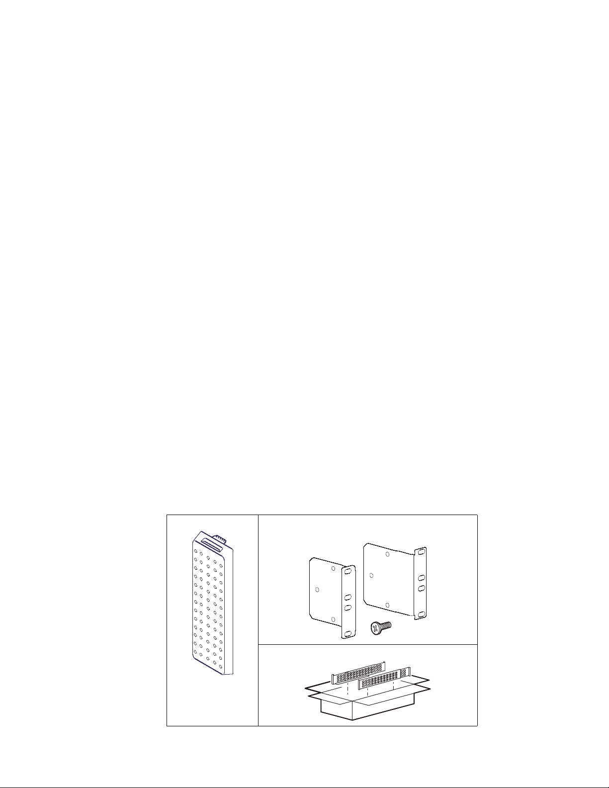
Package Contents
Inspect the contents upon receipt. Notify the carrier and dealer if the unit is damaged.
Front bezel • 1 pair rack-mount brackets
• 6 flat head screws to secure rack-mount brackets
Rail kit
34a
Smart-UPS On-Line Step-Down Transformer SRT5KRMTF2
Page 3
Specifications
For additional speci f ications refer to the APC by Schneider Electri c web site, www.apc.com.
Environmental
Temperature
Operating
Storage
Operating
Maximum Elevation
Storage
Humidity
Protection Class
0% to 95% relative humidity, non-condensing
IP 20 rating
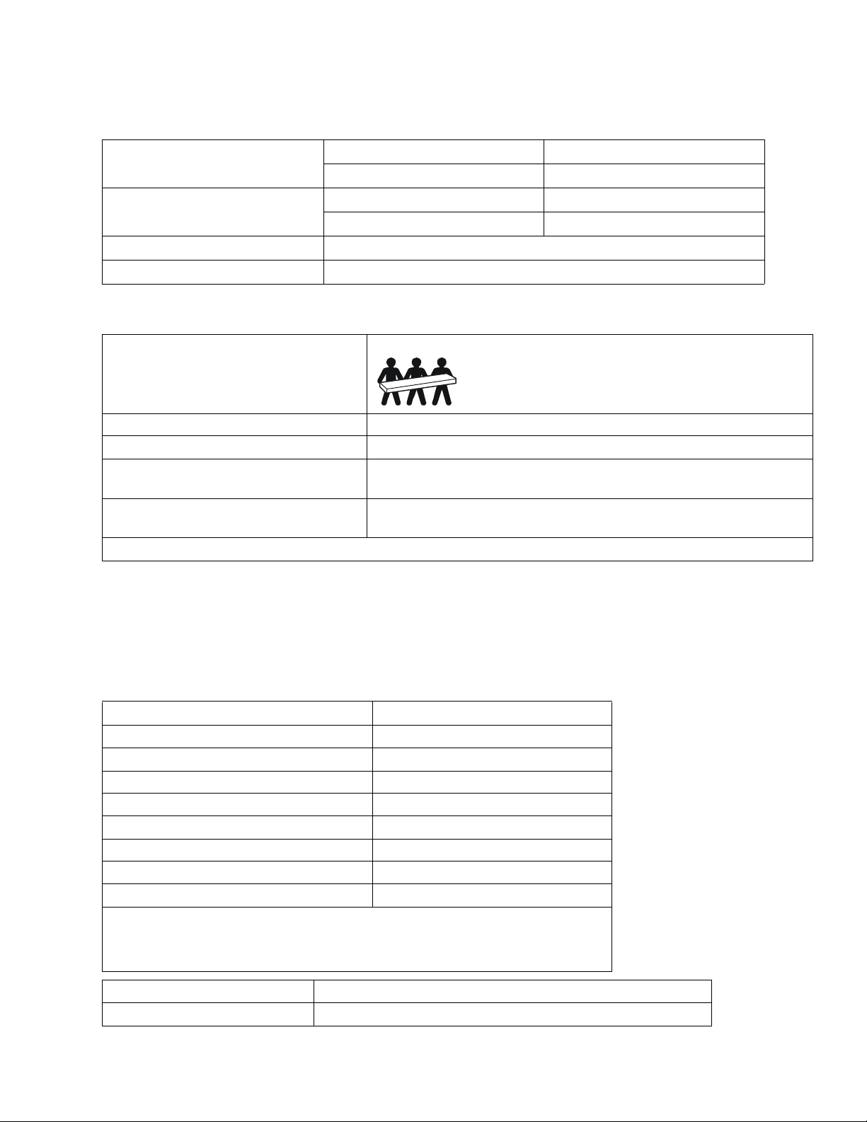
Physical
Lifting guidelines 32 - 55 kg (70 - 120lb)
Unit weight, without packaging 54.6 kg (120 lb)
Unit weight, with packaging 63.6 kg (140 lb)
Unit dimensions without packaging
Height x Width x Depth
Unit dimensions with packaging
Height x Width x Depth
The model and serial numbe rs a r e on a small label located on the rear panel.
130 mm x 432 mm x 719.4 m m
5 in x 17 in x 28.3 in
330 mm x 610 mm x 960 mm
13 in x 24 in x 37. 8 in
0º to 40º C (32º to 104º F)
-15º to 45º C (5º to 113º F)
0 - 3,000 m (0 - 10,000 ft)
0 - 15,000 m (50,000 ft)
Electrical
Operation above th e input voltage range may cause equipment damage.
Operation below the input voltage range may ca use overload or automatic shutdown. When c onnecting directly to a
branch circuit, check that the line voltage is within specifications. When connecting to the UPS, check that the line
voltage into the UPS is within specifications before transferring to bypass mode.
Installation With Line Cord
Nominal Input Voltag e (Vac)
Nominal Output Voltage (Vac)
Input V oltage Range (Vac)
Input Current Rating
Line Frequency (Hz)
Efficiency
Maximum Input Power
Maximum Output Pow e r (VA)
*For continuous ope ratio n bel ow V i n = 205 Vac, the output lo ad mus t be redu ced to l imit
the maximum input curre nt to the amount specified above. Continuous operation above
the maximum specified input current may cause the unit to overheat and shut down.
Contact APC by Schneider Electric for additional information.
Input Power Distribution
Output Power Distribution
3 ft cord with L6-30P
(2) 15 A
208 Vac
120 Vac
185 - 230 Vac *
24 A
50/60 Hz
90-95%
5000 VA
4500 VA
circuits with (4) 5-20R and (2) 15 A circuits with (2) 5-20R
Smart-UPS On-Line Step-Down Transformer SRT5KRMTF 3
Page 4

Rack Installation
s
u
o
1
0
0
suo1009a
Install rails
For details on support rail installation, refer to the instructions in the rail kit.
Install transfor mer
CAUTION
DAMAGE TO EQUIPMENT OR PERSONNEL
The equ
•
•Always use the recommended number of screws to secure brackets to the UPS and transformer.
•Always install the t ransformer above the UPS in the rack.
•Always install the optional bypass panel above the transformer in the rack.
Failure to follow these ins tructions can resul t in equipm ent damage and minor or moderate i njury
ipment is heavy. Always practice safe lift ing techniques adeq uate for the weight of the equipment.
a
8
a
0
1
0
1
o
u
s
Smart-UPS On-Line Step-Down Transformer SRT5KRMTF4
Page 5

Connecting Equipment and Power to the Transformer
Rear panel
suo1013a
Output 15 A Max.
Output 15 A Max.
Overload protector
Input Overload protector
Overload protector
Overload protector
Output 15 A Max.
Output 15 A Max.
Overload protector
Input power cord
Start-Up
CAUTION
DAMAGE TO EQUIPMENT OR PERSONNEL
•Disconnect the mains input circuit breaker before installing or servic ing the UPS or transformer or connected equipment.
•
Di
sconnect int ernal and external batt eries before installing or servicing the UPS or connected equipm ent.
The UPS
•
UPS
•
•Disconnect equipment from the UPS and transformer before servicing any equipment.
•
Do not
•
O
nly one of the cooli ng fans ope rat e when the t ransfo rmer temper at ure is less than 100°F. The redundant f an operat es ab
10
0°F or when the main fan fails.
Failure to follow these instructions can result in equi pm ent damage and minor or moderate injur y
contains i nternal and external batteries that may present a shock hazard even when disconnected from the mains.
and transfor me r pl uggable outlets may be energized by remote or automatic control at any time.
use the UPS as a safety disconnect.
ove
1. Check that all power is turned OFF.
2. Connect all load equipm ent to the transformer receptacles.
Note: Each recept acle group is protected by a circuit brea ker. A colored label identi fies each circui t and the
corresponding breaker.
3. Switch the transformer input circuit breaker ON.
4. Turn on output circuit breakers as needed.
5. Turn on all conn ec ted equipment.
Smart-UPS On-Line Step-Down Transformer SRT5KRMTF 5
Page 6

Service
If the unit requires service, do not return it to the dealer. Follow these steps:
1. Review the Troubleshooting section of the manual to eliminate common problems.
2. If the problem persists, contact APC Customer Support through the APC web site, www.apc.com.
a. Note the model number and serial number and the date of purchase . The model and serial
numbers are located on the rear panel of the unit and are a vailable through the LCD display
lect models.
se
b. Call APC Support and a technician will atte mpt to solve the problem over the phone. If this is
not possible, the technician will issue a Returned Materi al Authorization Number (RMA#).
c. If the unit is under warranty, the repairs are free.
on
d. Service procedu res a nd returns may vary internationally. Refer to the APC web site for countr
cific instructions.
spe
3. Pack the unit properly to avoid damage in transit . Never use foam beads for packaging. Damage sustained in
transit is not cove red under warranty.
a. Note: When shipping within the United States, or to the United States always
DISCONNECT ONE UPS BATTERY before shipping in compliance with U.S.
Department of Transportation (DOT) and IATA regulations. The internal batteries may
remain in the UPS.
b. Ba tteries may remain connected in the XB P during shipment. Not all units utilize XLBPs.
4. Write the RMA# provided by Customer Support on the outside of the package.
5. Return the unit by insured, prepaid carrier to the address provided by Customer Support.
y
Smart-UPS On-Line Step-Down Transformer SRT5KRMTF6
Page 7

Limited Factory Warranty
Schneider Electri c IT Corporation (SEIT), warrants its products to be free from defects in materials and workmanship
for a period of two (2) years from the date of purchase. The SEIT obligation under this warranty is limited to repairing
or replacing, at its own sole option, any such defective products. Repair or replacement of a defect ive product or part
thereof does not exte nd the original warra nty period.
This warranty applies only to the original purchaser who must have properl y registered the product within 10 days of
purchase. Products ma y be re gistered onlin e at warran ty.apc.com.
SEIT shall not be liab le under the warranty if its testing and examination disclose tha t the alleged defect in the product
does not exist or was caused by end user or any third person misuse, negligence, improper instal lation, testing,
operation or use of the product contrary to SEIT recommendations of specifications. Further, SEIT shall not be liable
for defects resulti ng from: 1 ) unau thorize d attemp ts to re pair or m odify the produc t, 2) inc orrect or inade quate ele ctric al
voltage or connection, 3) inappropriate on site operation conditions, 4) Acts of God, 5) exposure to the elements, or 6)
theft. In no event shall SEIT have any liability under this warranty for any product where the serial number has been
altered, defaced, or removed.
EXCEPT AS SET FORTH ABOVE, THERE ARE NO WARRANTIES, EXPRESS OR IMPLIED, BY
OPERATION OF LAW OR OTHERWISE, APPLICABLE TO PRODUCTS SOLD, SERVICED OR
FURNISHED UNDER THIS AGREEMENT OR IN CONNECTION HEREWITH.
SEIT DISCLAIMS ALL IMPLIED WARRANTIES OF MERCHANTAB ILIT Y, SATISFACTION AND
FITNESS FOR A PARTICULAR PURPOSE.
SEIT EXPRESS WARRANTIES WILL NOT BE ENLARGED, DIMINISHED, OR AFFECTED BY AND NO
OBLIGATION OR LI ABILITY WILL ARISE OUT OF, SEIT RENDERING OF TECHNICAL OR OTHER
ADVICE OR SERVICE IN CONNECTION WITH THE PRODUCTS.
THE FOREGOING WARRANTIES AND REMEDIES ARE EXCLUSIVE AND IN LIEU OF ALL OTHER
WARRANTIES AND REMEDIES. THE WARRANTIE S SET FORTH ABOVE CONSTITUTE SEIT’S SOLE
LIABILITY AND PURCHASER EXCLUSIVE REMEDY FOR ANY BREACH OF SUCH WARRANTIES.
SEIT WARRANTIES EXTEND ONLY TO ORIGINAL PURCHASER AND ARE NOT EXTENDED TO ANY
THIRD PARTIES.
IN NO EVENT SHALL SEIT, ITS OFFICERS, DIRECTORS, AFFILIATES OR EMPLOYEES BE LIABLE
FOR ANY FORM OF INDIRECT, SPECIAL, CONSEQUENTIAL OR PUNITIVE DAMAGES, ARISING
OUT OF THE USE, SERVICE OR INSTAL LATION OF THE PRODUCT S, WH ETHER SUCH DAMAGES
ARISE IN CONTRACT OR TORT, IRRESPECTIVE OF FAULT, NEGLIGENCE OR STRICT LIABILITY
OR WHETHER SEIT HAS BEEN ADVISED IN ADVANCE OF THE POSSIBILITY OF SUCH DAMAGES.
SPECIFICALLY, SEIT IS NOT LIABLE FOR AN Y COSTS, SUCH AS LOST PROFITS OR REVENUE,
WHETHER DIRECT OR INDIRECT, LOSS OF EQUIPMENT, LOSS OF USE OF EQUIPMENT, LOSS OF
SOFTWARE, LOSS OF DATA, COSTS OF SUBSTITUANTS, CLAIMS BY THIRD PART IES, OR
OTHERWISE.
NOTHING IN THIS LIMITED WARRANTY SHALL SEEK TO EXCLUDE OR LIMIT SEIT LIABILITY
FOR DEATH OR PERSONAL INJURY RESULTING FROM ITS NEGLIGENCE OR ITS FRAUDULENT
MISREPRESENTATION OF TO THE EXTENT THAT IT CANNOT BE EXCLUDED OR LIMITED BY
APPLICABLE LAW.
To obtain service under wa rranty you must obtain a Returned Material Authorization (RMA) number from customer
support. Customers with warranty clai ms issues may access the SEIT worldwide cust omer support network through the
APC web site: www.apc.com. Selec t your cou ntry f rom the count ry sel ecti on drop down menu. Open the Support ta b at
the top of the web page to obtain inform ation for customer support in your region. Products must be returned with
transportation c harge s prepa id and must be accomp anied by a brie f desc ription of the pro blem encou ntered and proof of
date and pl ac e o f pu r chase.
Smart-UPS On-Line Step-Down Transformer SRT5KRMTF 7
Page 8

© 2015 APC by Schneider Electric. APC, the APC logo, Sm art-UPS and PowerChute are owned by
Schnei der Elec tric Indus tr ies S.A.S. or their affiliated co m p an ies. All ot her trade m ar k s are prope rty of
their respective owners.
EN 990-5473A
3/2015
 Loading...