

Page 1
Selection Guide
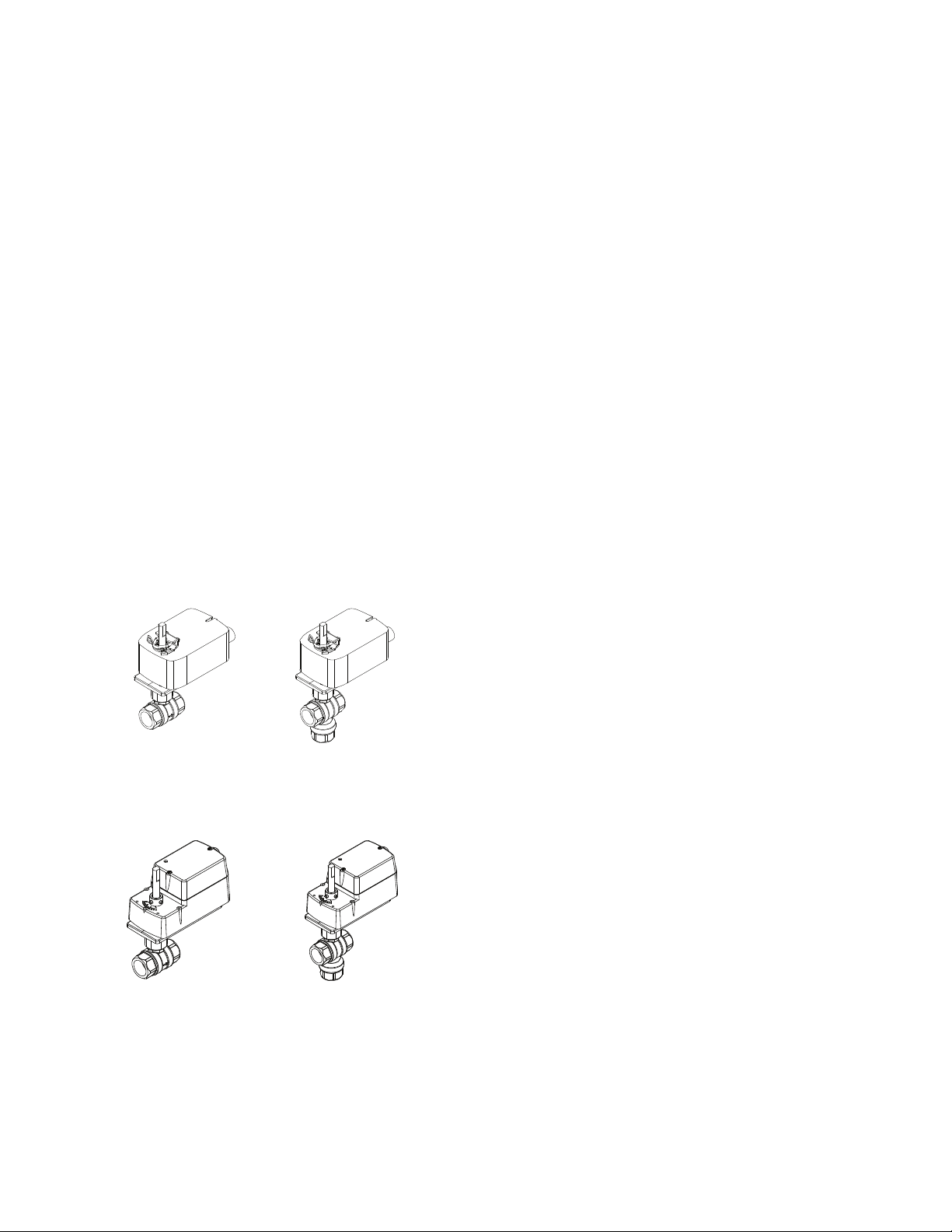
Ball Valve Assemblies with SmartX
Actuators
Selection Guide
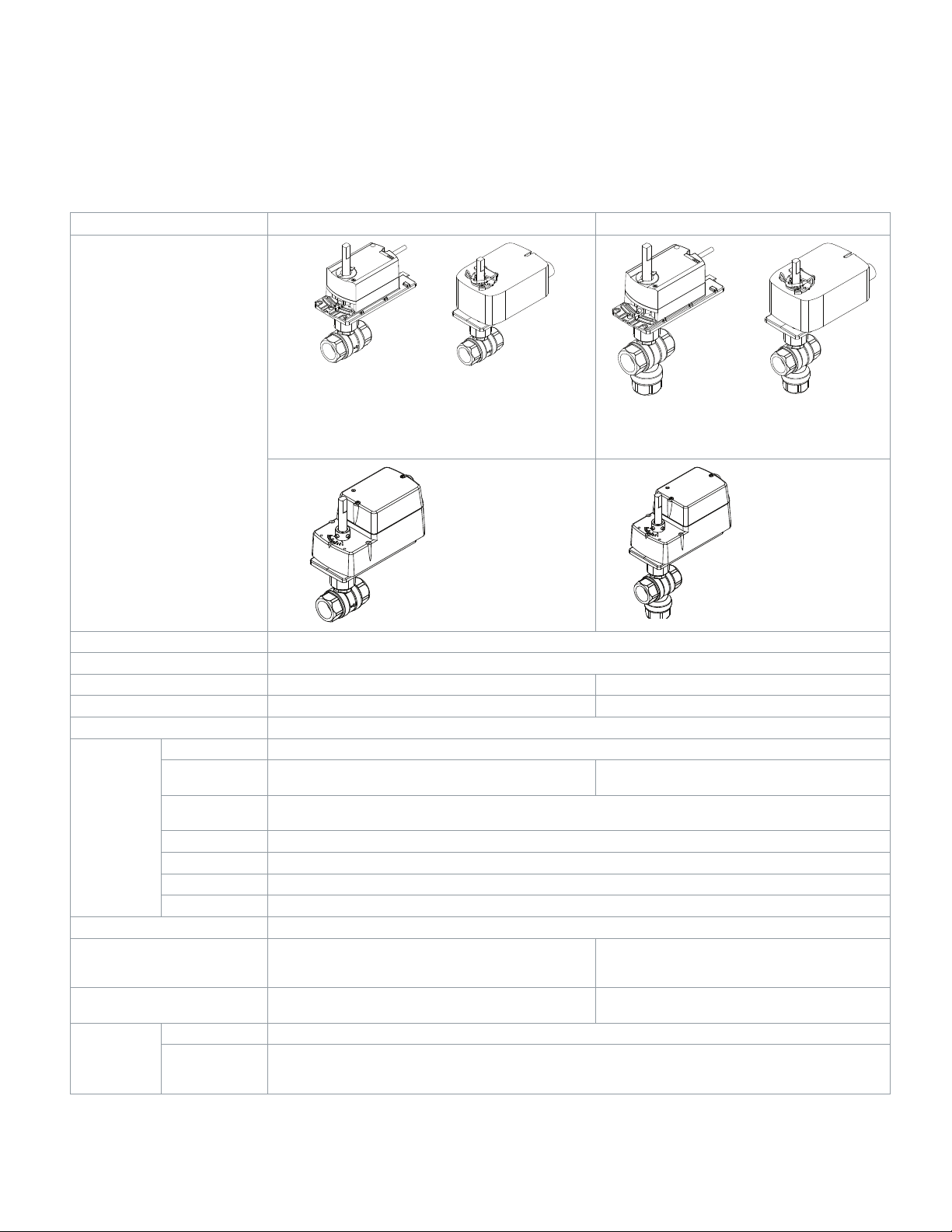
The Schneider Electric VA, VF, and VS-2xx3-xxx-9-xx series
Ball Valve Assemblies are complete actuator/valve assemblies that accept two-position, floating, or proportional control
signals from a DDC system or a thermostat, for control of hot
or chilled water, or solutions of up to 50% glycol. They consist
of direct-coupled, SmartX, spring return or non-spring return
actuators mounted on 2-way (1/2” to 3”) and 3-way (1/2” to 2”)
ball valve bodies. Typical applications include reheat on VAV
boxes, fan coil units, hot and chilled water coils in air handling
units, and unit ventilators.
Ball Valve Assemblies with SmartX
Actuators
Vx-2xx3-5xx-9-xx series ball valve assemblies are available
with either spring return or non-spring return SmartX
tors.
Vx-22x3-5xx-9-xx
2-Way Assembly with
Spring Return Actuator
Vx-2313-5xx-9-xx
3-Way Assembly with
Spring Return Actuator
Vx-2xx3-8xx-9-xx Spring return valve assemblies equipped
with Mx4D-x0x3 SmartX Actuators, respectively.
®
Actua-
Contents
Ball Valve Assemblies with SmartX Actuators. ...................................1
Ball Valve Body/Linkage Assemblies.
Features and Benefits
Ball Valve Assembly Selection Procedure
Applicable Literature.
Part Numbering System.
Ball Valve Assemblies Using SmartX 5xx Actuators
Ball Valve Assemblies Using SmartX 8xx Actuators
Port Codes.
2-Way Ball Valve Assemblies with SmartX Actuators
3-Way Ball Valve Assemblies with SmartX Actuators
Ball Valve Specifications.
Valve/Actuator Combinations..............................................................9
2-Way Ball Valve Assemblies Using SmartX Actuators
3-Way Mixing Assemblies Using SmartX Actuators
2-Way Ball Valve Assemblies Using SmartX Actuators
3-Way Mixing Assemblies Using SmartX Actuators
Actuator Specs and Valve Assembly Mounting Dimensions.
Assemblies with MF/MS41-6043/83 NSR SmartX Actuators
Assemblies with Mx40-704x SR SmartX Actuators
Installation Considerations.
Mounting Angle of Valve Assembly
Piping
Water System Maintenance
Sizing and Selection
Two-position Control
Flow Characterization: Proportional/Floating Control
3-Way Mixing Valves
Cavitation Limitations on Valve Pressure Drop
Using Pipe Reducers with 2-Way Ball Valve Assemblies
Using Pipe Reducers with 3-Way Ball Valve Assemblies
.........................................................................................6
...........................................................................................23
....................................................................2
.........................................................................3
....................................................................4
....................................................................8
..............................................................23
....................................................................24
....................................................................24
....................................................................25
................................................2
.....................................3
......................4
......................5
....................6
....................7
.................9
...................10
...............11
....................12
...........13
.......13
.....................16
............................................23
.........................................................24
..................25
............................26
............27
............30
Vx-22x3-8xx-9-xx
2-Way Assembly with
Mx4D Series Actuator
Vx-2313-8xx-9-xx
3-Way Assembly with
Mx4D Series Actuator
© 2019 Schneider Ele ctric . All rig hts res erve d. All tr ademarks are o wned by S chneid er Elect ric Ind ustri es SAS or its af filiat ed companies. Januar y, 2019 tc
Docume nt Numbe r: F-270 86-14
Page 2

Selection Guide
Ball Valve Body/Linkage Assemblies
Ball valve body/linkage assemblies allow field mounting of SmartX actuators.
Features and Benefits
Feature Benefit
Close-offs of 40 to 130 psi. Accommodates most close-off requirements.
Available in full range of line sizes, 1/2 in. to 3 in. for 2-way valves
and 1/2 in. to 2 in. for 3-way valves.
Cvs from 0.33 to 266. Permits optimal valve sizing, minimizing the need for pipe reducers.
Flow characterizing insert, made of glass-filled Noryl™. Provides equal percentage flow characteristic so that the heat output of
Available in both spring return and non-spring return models. Allows power loss mode requirement to be met for any given application.
Utilizes SmartX Actuators with two-position, floating, and proportional control.
All models equipped with pigtail leads. Eases installation. Reduced electrician costs.
Low-friction seals and o-rings. Allows the use of lower-torque actuators, reducing cost.
Valve body made of forged brass ASTM B283-06. Rated for static pressure of 360 psi at fluid temperatures of 20 to 250 °F
ANSI Class IV (0.01% of Cv) shutoff with 2-way valves. Allows accurate control, saves energy.
Choices of spring return direction. Provides Normally Closed or Normally Open spring return.
Thermally isolated mounting plate. Protects the actuator from excess cold or heat from chilled or hot water
Ball Valve Body/Linkage Assemblies are available separately. They
include anti-rotation clips for SmartX Actuators.
Satisfies a wide range of applications.
the coil is linear with respect to valve position.
Models to fit a wide range of applications.
(-7 to 121 °C).
passing through the valve. Discourages condensation.
Increases flexibility and minimizes inventory.
Januar y, 2019 tc © 2019 Schneider Ele ctric . All rig hts res erve d. All tr ademarks are o wned by S chneid er Elect ric Ind ustri es SAS or its af filiat ed companies.
Document Number: F-27086-14
Page 3

Page 4
Selection Guide
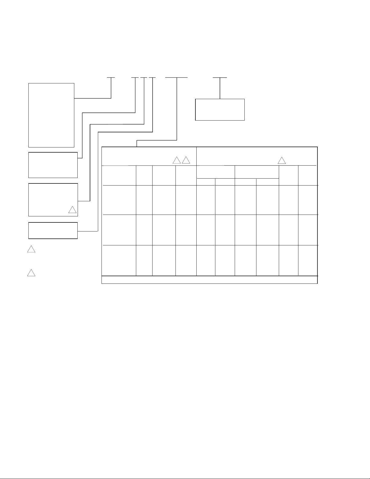
V x - 2 x x 3 - 5 x x - 9 - x x
Part Numbering System
Ball Valve Assemblies Using SmartX 5xx Actuators
Control
Signal Type
A = Two Position
F = Floating
S = Proportional
B = Valve Body &
Linkage
(less actuator)
a
Port Code
Refer to separate
Port Code table
Configuration
2 = 2 Way
3 = 3 Way Mixing
Material
1 = Nickel/Chromium
Plated Brass
5 = Stainless Steel
Connection
3 = Threaded NPT
1 Normal position for 3 way
spring return ball valve
assemblies refers to A to AB
ports.
3 Stainless steel ball is
available only on 2 way
versions.
3
2
Actuator Code Valves Used On
1
3
1-1/2" 1-1/2"
Normal 1/2 to 1" 1-1/4" to 3" to 2"
Model Code Position Voltage 2-way 3-way 2-way 3-Way 2-Way 3-way
Two-Position
MA40 7040 522 SR Close 120 Vac X X X X X X
MA40 7040 532 SR Open 120 Vac X X X X X X
MA40 7043 526 SR Close 24 Vac X X X X X X
MA40 7043 536 SR Open 24 Vac X X X X X X
Floating
MF41 6043 505 NSR 24 Vac X X X X
MF41 6083 506 NSR 24 Vac X X
MF40 7043 526 SR Close 24 Vac X X X X X X
MF40 7043 536 SR Open 24 Va c X X X X X X
Proportional
MS41 6043 505 NSR 24 Vac X X X X
MS41 6083 506 NSR 24 Vac X X
MS40 7043 526 SR Close 24 Va c X X X X X X
MS40 7043 536 SR Open 24 Vac X X X X X X
Valve Body/Linkage Assembly
SR = Spring Return
NSR = Non Spring Return
a
Includes valve body, linkage, and anti rotation clips for spring return and non spring return SmartX
actuators, listed above. Ordered separately.
Note: Not all model configurations are available as factory assemblies. You can purchase the the actuator
and a VB 22x3 500 9 xx valve body and linkage separately for field assembly.
a
VB-22x3-500-9-xx, VB-2313-500-9-xx
Januar y, 2019 tc © 2019 Schneider Ele ctric . All rig hts res erve d. All tr ademarks are o wned by S chneid er Elect ric Ind ustri es SAS or its af filiat ed companies.
Document Number: F-27086-14
Page 5

Ball Valve Assemblies Using SmartX 8xx Actuators
V x - 2 x x 3 - 8 x x - 9 - x x
Control
Signal Type
A = Two Position
F = Floating
S = Proportional
B = Valve Body &
Linkage
(less actuator)
c
Configuration
2 = 2 Way
3 = 3 Way Mixing
Material
1 = Nickel/Chromium
Plated Brass
5 = Stainless Steel
3
Connection
3 = Threaded NPT
1 Normal position for 3 way spring
return ball valve assemblies refers to
A to AB ports.
3 Stainless steel ball is available only
on 2 way versions.
Actuator Code Valves Used On
1-1/4” 1-1/4”
Normal 1/2” to 1” to 3” to 2”
a
Code Position Voltage Type 2-way 3-way 2-way 3-way
Model
Two-Position
MA4D 7030 000 815 SR Open 120 Va c X X
MA4D 8030 000 817 SR Closed 120 Vac X X
MA4D 7033 100 821 SR Open 24 Vac X X
MA4D 8033 100 831 SR Closed 24 Vac X X
Floating
MF4D 7033 100 821 SR Open 24 Vac X X
MF4D 8033 100 831 SR Closed 24 Va c X X
MF4D 6083 100 N/Ab NSR 24 Vac X X X X
Proportional
MS4D 7033 100 821 SR Open 24 Vac 2 10 Vdc X X
MS4D 7033 120 N/Ab SR Open 24 Va c 0 3 Vdc X X
MS4D 7033 130 N/Ab SR Open 24 Vac 6 9 Vdc X X
MS4D 7033 150 N/Ab SR Open 24 Vac 0 10 Vdc X X
MS4D 7033 160 N/Ab SR Open 24 Vac 4 20 mA X X
MS4D 8033 100 831 SR Closed 24 Vac 2 10 Vdc X X
MS4D 8033 120 N/Ab SR Closed 24 Vac 0 3 Vdc X X
MS4D 8033 130 N/Ab SR Closed 24 Vac 6 9 Vdc X X
MS4D 8033 150 N/Ab SR Closed 24 Vac 0 10 Vdc X X
MS4D 8033 160 N/Ab SR Closed 24 Vac 4 20 mA X X
Valve Body/Linkage Assemblyc VB-22x3-500-9-xx, VB-2313-500-9-xx
SR = Spring Return NSR = Non Spring Return
a “ 000” models have appliance cables. “ 1X0” models have plenum cables.
b Factory assemblies not available. Purchase actuator and valve body separately and field
assemble.
c Includes valve body, linkage, and anti rotation clips for spring return and non spring return
SmartX actuators, listed above. Ordered separately.
Selection Guide
Port Code
Refer to separate
Port Code table
1
3
© 2019 Schneider Ele ctric . All rig hts res erve d. All tr ademarks are o wned by S chneid er Elect ric Ind ustri es SAS or its af filiat ed companies. Januar y, 2019 tc
Docume nt Numbe r: F-270 86-14
Page 6
Selection Guide
Cv =
gpm
∆P
Cv
1.156
kvs
kvs =
m3/h
∆P
Port Codes
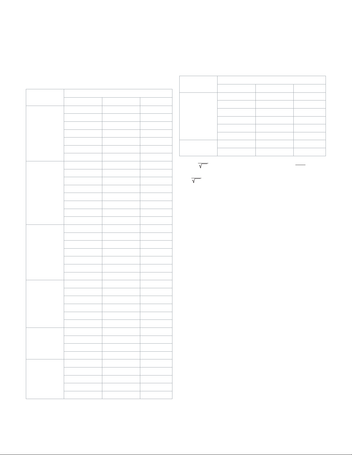
2-Way Ball Valve Assemblies with SmartX Actuators
Table-1. 2-Way Ball Valve Assemblies - Sizes, Port Codes, and
Cvs.
Size
in.
1/2
¾
1
1¼
1½
2
Port Code Cv
01 0.38 0.33
02 0.68 0.59
03 1.3 1.1
04 2.6 2.2
05 4.7 4.1
06 8.0 6.9
07 11.7
11 0.31 0.27
12 0.63 0.54
13 1.2 1.0
14 2.5 2.2
15 4.3 3.7
16 10.1 8.7
17 14.7
18 28.6
21 4.4 3.8
22 9.0 7.8
23 15.3 13.2
24 26.1 22.6
25 28.4
26 43.9
27 54.2
41 4.4 3.8
42 8.3 7.2
43 14.9 12.9
44 36.5 31.6
45 41.1
46 102.3
51 22.8 19.7
52 41.3 35.7
53 73.9
54 171.7
61 41.7 36.1
63 71.1 61.5
65 108
66 210 181.7
67 266
2-Way
a
b
b
b
b
b
b
b
b
b
b
Kvs
10.1
12.7
24.7
24.6
38.0
46.9
35.6
b
b
88.5
63.9
148.5
93.4
230.1
a
Size
in.
Port Code Cv
2-Way
a
71 45 38.9
72 55 47.6
2½
73 72.3 62.5
74 101 87.4
75 162 140.1
76 202
3
a -
b - Denotes a full port valve, without the characterized insert.
(where DP is measured in psi)
(where DP is measured in bar; 1 bar = 100 kPa)
82 63 54.5
85 145
b
b
=
Kvs
174.7
125.4
a
Januar y, 2019 tc © 2019 Schneider Ele ctric . All rig hts res erve d. All tr ademarks are o wned by S chneid er Elect ric Ind ustri es SAS or its af filiat ed companies.
Document Number: F-27086-14
Page 7
Cv =
gpm
∆
Cv
1.156
kvs
kvs =
m3/h
∆P
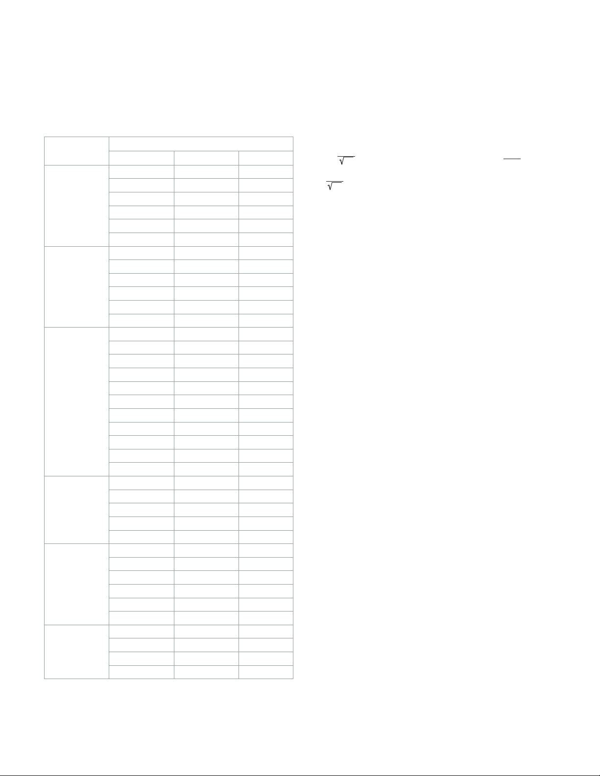
3-Way Ball Valve Assemblies with SmartX Actuators
Table-2. 3-Way Ball Valve Assemblies - Sizes, Port Codes, and Cvs
Selection Guide
Size
in.
1/2
¾
1
1¼
1½
2
3-Way
Port Code A Port Cv
01 0.33 0.28
02 0.59 0.51
03 1 0.86
04 2.4 2.1
05 4.3 3.7
06 8.0
11 0.40 0.35
12 0.66 0.57
13 1.3 1.1
14 2.4 2.1
15 3.8 3.3
16 11
21 0.40 0.35
22 0.65 0.56
23 1.3 1.1
24 2.3 2.0
25 3.5 3.0
26 4.5 3.9
27 8.6 7.4
28 10 8.6
29 14.9 12.9
30 22.3
31 30.8
41 4.1 3.5
43 8.7 7.5
44 12.7 11.0
45 19.4
46 34.1
51 4 3.5
52 8.3 7.2
53 13.4 11.6
54 23.5 20.3
55 32
56 61.1
61 23.9 20.7
62 38.2 33.0
63 56.7
64 108.5
a b
c
c
c
c
c
c
c
c
c
c
Kvs
6.9
9.5
19.3
26.6
16.8
29.5
27.7
52.8
49.0
93.8
a
a -
b - B port Cv is 80% of A por t Cv.
c - Denotes a full port valve, without the characterized insert.
(where DP is measured in psi)
P
(where DP is measured in bar; 1 bar = 100 kPa)
=
© 2019 Schneider Ele ctric . All rig hts res erve d. All tr ademarks are o wned by S chneid er Elect ric Ind ustri es SAS or its af filiat ed companies. Januar y, 2019 tc
Docume nt Numbe r: F-270 86-14
Page 8
Selection Guide
Ball Valve Specifications
Table-3. Specifications for Ball Valve Assemblies
Valve Assembly Series 2-Way 3-Way Mixing
Ball Valve Assemblies using
SmartX Actuators
Non-Spring Return
Vx-22x3-505-9-P
Vx-22x3-506-9-P
Spring Return
Vx-22x3-5xx-9-P
Non-Spring Return
Vx-2313-505-9-P
Vx-2313-506-9-P
Spring Return
Vx-22x3-81x-9-P
Vx-22x3-82x-9-P
Vx-22x3-83x-9-P
Applications Chilled or Hot Water, up to 50% Glycol Solution
Type of End Fitting NPT Screwed
Size 1/2 in. through 3 in. 1/2 in. through 2 in.
Valve Assembly Series Vx-22x3-xxx-9-P Vx-2313-xxx-9-P
Flow Type Equal Percentage
Body Forged Brass (ASTM B283-06)
Ball 1 = Nickel/Chromium-Plated Brass
Characterizing
Material
Maximum Static Pressure 360 psig (25 bar) at 250 °F (121 °C)
Maximum Operating Differential
Pressure
Seat Leakage ANSI Class IV (0.01% of Cv) ANSI Class IV (0.01% of Cv),
Fluid (water)
Temperature
Insert
Stem Stainless Steel
Ball Seals Reinforced Teflon® Seals with EPDM O-Rings
Stem Seals EPDM O-Rings
Mounting Plate Glass-filled Polymer
Same as close-off pressures shown in Table-4 or
Table-6. Refer to “Cavitation Limitations on Valve
Minimum 20 °F (-7 °C)
Maximum 250 °F (121 °C)
5 = Stainless Steel
Glass-filled Noryl
Same as close-off pressures shown in Table-5 or
Table-7. Refer to “Cavitation Limitations on Valve
Pressure Drop” on page 26.
Nickel/Chromium-Plated Brass
Pressure Drop” on page 26.
piped coil-side outlet to A only
Spring Return
Vx-2313-5xx-9-P
Spring Return
Vx-2313-81x-9-P
Vx-2313-82x-9-P
Vx-2313-83x-9-P
Januar y, 2019 tc © 2019 Schneider Ele ctric . All rig hts res erve d. All tr ademarks are o wned by S chneid er Elect ric Ind ustri es SAS or its af filiat ed companies.
Document Number: F-27086-14
Page 9
Page 10
Page 11

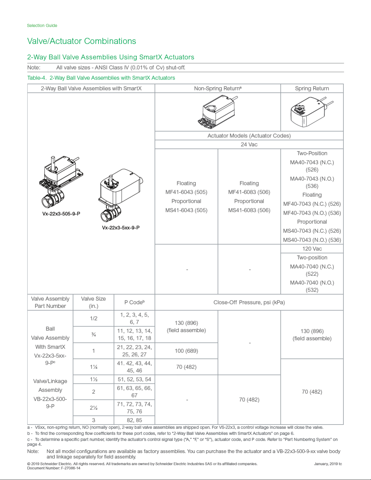
2-Way Ball Valve Assemblies Using SmartX Actuators
Note: All valve sizes - ANSI Class IV (0.01% of Cv) shut-off.
Table-6. 2-Way Ball Valve Assemblies with SmartX Actuators
2-Way Ball Valve Assemblies with SmartX Spring Return
Actuator Models (Actuator Codes)
24 Vac
Two-Position
MA4D-7033-100 (N.O.) (821)
MA4D-8033-100 (N.C.) (831)
Floating
MF4D-7033-100 (N.O.) (821)
Spring Return
Vx-22x3-81x-9-P
Vx-22x3-82x-9-P
Vx-22x3-83x-9-P
Valve Assembly
Part Number
Ball
Valve Assembly
with SmartX
Vx-22x3-5xx-9-P
Valve Size
c
(in.)
P Code
b
1/2 1, 2, 3, 4, 5, 6, 7 130 (896)
¾
11, 12, 13, 14, 15, 16, 17,
18
1 21, 22, 23, 24, 25, 26, 27 100 (689)
1¼ 41. 42, 43, 44, 45, 46
1½ 51, 52, 53, 54
Valve/Linkage
Assembly
VB-22x3-500-9-P
b - To find the corresponding flow coefficients for these port codes, refer to “2-Way Ball Valve Assembly Dimensions” on page 21.
c - To determine a specific part number, identify the actuator’s control signal type (“A,” “F,” or “S”), actuator code, and P code. Refer to “Part Numbering System” on
page 4.
Note: Not all model configurations are available as factory assemblies. You can purchase the the actuator and a VB-22x3-500-9-xx valve body
and linkage separately for field assembly.
2 61, 63, 65, 66, 67
2½ 71, 72, 73, 74, 75, 76
3 82, 85
MF4D-8033-100 (N.C.) (831)
Proportional
MS4D-7033-100 (N.O.) (821) to (829)
MS4D-8033-100 (N.C.) (831) to (839)
120 Vac
Two-position
MA4D-7030-100 (N.O.) (815)
MA4D-8030 (N.C.) (817)
230 Vac
Two-Position
MA4D-7031-100 (N.O.) (816)
MA4D-8031-100 (N.C.) (818)
Close-Off Pressure, psi (kPa)
130 (896)
-
Selection Guide
© 2019 Schneider Ele ctric . All rig hts res erve d. All tr ademarks are o wned by S chneid er Elect ric Ind ustri es SAS or its af filiat ed companies. Januar y, 2019 tc
Docume nt Numbe r: F-270 86-14
Page 12

Selection Guide
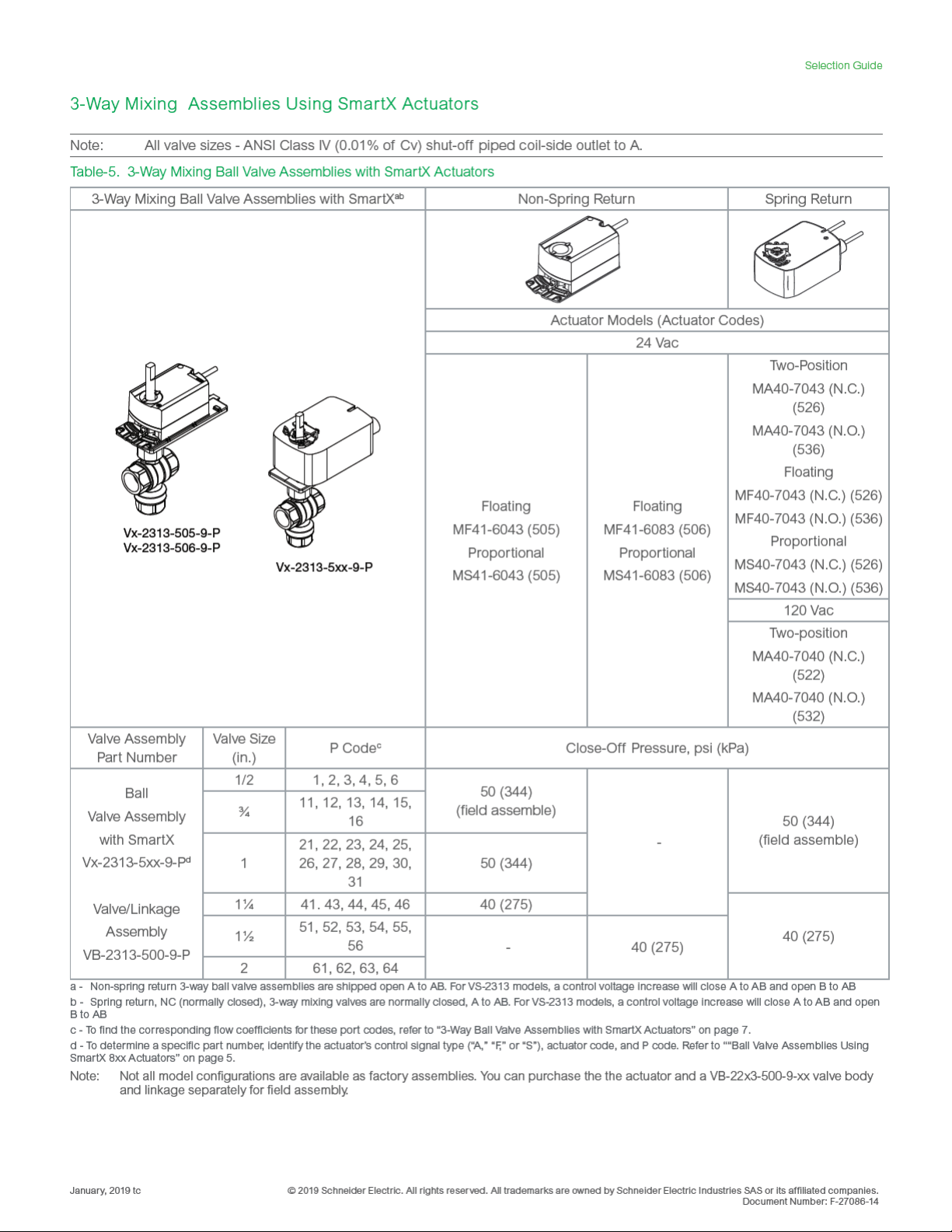
3-Way Mixing Assemblies Using SmartX Actuators
Note: All valve sizes - ANSI Class IV (0.01% of Cv shut-off piped coil-side outlet to A.
Table-7. 3-Way Mixing Ball Valve Assemblies with SmartX Actuators
Valve Assembly
Part Number
Ball
Valve Assembly
with SmartX
Vx-2313-8xx-9-P
Valve/Linkage
Assembly
VB-2313-500-9-P
3-Way Mixing Ball Valve Assemblies
with SmartX
Valve Size
(in.)
b
Spring Return
Vx-2313-81x-9-P
Vx-2313-82x-9-P
Vx-2313-83x-9-P
P Code
1/2 1, 2, 3, 4, 5, 6
¾ 11, 12, 13, 14, 15, 16
d
1
21, 22, 23, 24, 25, 26, 27, 28, 29,
30, 31
1¼ 41. 43, 44, 45, 46
1½ 51, 52, 53, 54, 55, 56
2 61, 62, 63, 64
Spring Return
Actuator Models (Actuator Codes)
24 Vac
Two-Position
MA4D-7033-100 (N.O.) (821)
MA4D-8033-100 (N.C.) (831)
Floating
MF4D-7033-100 (N.O.) (821)
MF4D-8033-100 (N.C.)(831)
Proportional
Two-Position
MA4D-7030-100 (N.O.)
(815)
MA4D-8030-100 (N.C.)
(817)
MS4D-7033-100 (N.O.)(821)
MS4D-8033-100 (N.C.)(831)
c
Close-Off Pressure, psi (kPa)
50 (344)
-
b - Spring retur n, NC (normally closed), 3-way mixing valves are normally A to AB closed. For VS-2313, a control voltage increase will open A to AB and close B to AB
c - To find the corresponding flow coefficients for these port codes, refer to “3-Way Ball Valve Assemblies with SmartX Actuators” on page 7.
d - To determine a specific part number, identify the actuator’s control signal type (“A,” “F,” or “S”), actuator code, and P code. Refer to ““Ball Valve Assemblies Using
SmartX 8xx Actuators” on page 5.
Note: Not all model configurations are available as factory assemblies. You can purchase the the actuator and a VB-22x3-500-9-xx valve body
Januar y, 2019 tc © 2019 Schneider Ele ctric . All rig hts res erve d. All tr ademarks are o wned by S chneid er Elect ric Ind ustri es SAS or its af filiat ed companies.
Document Number: F-27086-14
and linkage separately for field assembly.
Page 13

Actuator Specs and Valve Assembly Mounting Dimensions
Assemblies with MF/MS41-6043/83 NSR SmartX Actuators
Table-8. Actuator Specifications
Inputs
MF41-6043 and MF41-6083: Floating three-position control, 24 Vac.
MS41-6043 and MS41-6083: Proportional, 0 to 10 Vdc; input resistance 100K ohms.
Control Signal
Power Requirements
Connections 3 ft. (0.9 m) long, 18 AWG plenum-rated leads.
Motor Type Synchronous
Outputs
Electrical
Control signal adjustment available with MS41-6043-520 and MS41-6043-522:
Start point (offset) - Between 0 and 5 Vdc (factory setting = 0 Vdc)
Span - 2 to 30 Vdc
All 24 Vac circuits are Class 2.
Part Number
MF41-6043 and MF41-6083
MS41-6043 and MS41-6083
Feedback potentiometer available for MF41-6043/6083-510: 0 to 1000 ohms < 10 mA
Position feedback voltage for MS41-6043/6083: 0 to 10 Vdc, 1 mA
Auxiliary Switches: Dual auxiliary switches available with MF41-6043/6083-502, MS41-6043/6083-502, and
MS41-6083-522 when these actuators are ordered as separate units. Auxiliary switches are not offered with
factory ball valve assemblies.
AC Rating: 24 Vac, 4 A resistive, 2 A inductive Switch hysteresis: 3° rotation
DC Rating: 12 to 30 Vdc, DC 2 A
Timing:
Part Num-
ber
MF41-6043
MS41-6043
MF41-6083
MS41-6083
90° Timing in Sec.
At 60 Hz At 50 Hz
90 108
125 150
Voltage Running VA Holding VA Watts
24 Vac +20/-
15%
Power Input @ 50/60 Hz
2.3 - 2.0
3.3 1.2 3.0
Switch Range:
Switch A - 0 to 90° range in 5° intervals
Recommended range usage - 0 to 45°
Factory setting - 5°
Switch B - 0 to 90° range in 5° intervals
Recommended range usage - 45 to 90°
Factory setting - 85°
Selection Guide
Output torque rating: 44 lb-in. (5 N-m) for Mx41-6043; 88 lb-in. (10 N-m) for Mx41-6083
Stroke: Normal angle of rotation is 90°, limited to a maximum of 95°. Field adjustable to limit travel on either
Mechanical
Environment
Temperature Limits
Humidity 5 to 95% RH, non-condensing.
Locations NEMA Type 2 (IEC IP54).
Agency Listings (Actuator)
UL UL-873, Underwriters Laboratories.
cUL Canadian Standards C22.2 No. 24-93.
European Community EMC Directive (89/336/EEC). Emissions (EN50081-1). Immunity (EN50081-2).
© 2019 Schneider Ele ctric . All rig hts res erve d. All tr ademarks are o wned by S chneid er Elect ric Ind ustri es SAS or its af filiat ed companies. Januar y, 2019 tc
Docume nt Numbe r: F-270 86-14
end of stroke.
Position indicator: Adjustable pointer is provided for position indication.
Output shaft setscrew: Tightening torque 55 to 60 lb-in. (6.3 to 6.8 N-m).
Shipping and storage: -40 to 158 °F (-40 to 70 °C) ambient.
Operating: -25 to 130 °F (-32 to 55 °C) ambient.
NOTE: Check the valve operating temperature limit. The minimum valve temperature limit is 20 °F (6.7 °C)
Page 14

Selection Guide
3 (76)
B
2-Way Ball Valve Assembly Dimensions
Table-9. 2-Way Ball Valve Assembly Dimensions
Valve Assembly
Part Number
Valve Size
in.
1/2
¾
P Code
a
1, 2, 3, 4, 5, 7 2-3/8 (60) 7 (178) 8¼ (210) 3-1/8 (79)
6 2-5/8 (67) 7 (178) 8½ (216) 3-3/8 (86)
11, 12, 13,
14, 15, 17
Valve Dimensions in inches (mm) Refer to Figure 1
A B C D
2-7/16 (62) 7 (178) 8¼ (210) 3¼ (83)
16, 18 2¾ (70) 7 (178) 8½ (216) 3-3/8 (86)
21, 23 3-1/16 (78) 7 (178) 8-7/8 (225) 3-5/8 (92)
2-Way
1
VF-22x3-505-9-P
VF-22x3-506-9-P
VS-22x3-505-9-P
VS-22x3-506-9-P
1¼
1½
2
2½
3 82, 85 5-11/16 (144) 8-1/8 (206)
a - To find the corresponding flow coefficients for these port codes, refer to “2-Way Ball Valve Assemblies with SmartX Actuators” on page 6.
22, 25 2¾ (70) 7 (178) 8½ (216) 3-3/8 (86)
24, 26 4½ (114) 7-3/8 (187) 9-3/8 (238) 3-7/8 (98)
27 3 (76) 7 (178) 8-7/8 (225) 3-5/8 (92)
41, 42, 43, 45 3 (76) 7 (178) 8-7/8 (225) 3-5/8 (92)
44, 46 3-5/8 (92) 7-1/8 (181) 9-3/8 (238) 3-¾ (95)
51, 53 3-7/16 (87) 7-1/8 (181) 9-3/8 (238) 3-¾ (95)
52, 54 4-1/16 (103) 7¼ (184) 9-7/8 (251) 4-1/16 (103)
61, 65 3-15/16 (100) 7¼ (184) 9-7/8 (251) 4 (102)
63, 66, 67 4-15/16 (125) 7-¾ (197) 10½ (267) 4-7/16 (113)
71, 72, 76,
73, 74, 75
5-3/8 (137) 8 (203) 10-¾ (273) 4½ (114)
10-11/16
(271)
4¼ (108)
C
A
Figure 1. Mx41-6043 or Mx41-6083 with 2-Way Ball Valve.
Januar y, 2019 tc © 2019 Schneider Ele ctric . All rig hts res erve d. All tr ademarks are o wned by S chneid er Elect ric Ind ustri es SAS or its af filiat ed companies.
Document Number: F-27086-14
D
Page 15

3 (76)
3-Way Mixing Ball Valve Assembly Dimensions
Table-10. 3-Way Ball Valve Assembly Dimensions
Selection Guide
Valve Assembly
Part Number
Valve Size
in.
P Code
a
Valve Dimensions in inches (mm) Refer to Figure 2
A B C D E
1/2 1, 2, 3, 4, 5, 6 2-5/8 (67) 7 (178) 9-¾ (248) 3-5/16 (84) 2 (51)
3-Way
VF-2313-505-9-P
VF-2313-506-9-P
VS-2313-505-9-P
VS-2313-506-9-P
¾
1
1¼
1½
11, 12, 13,
14, 15, 16
21, 22, 23,
24, 25, 28
27, 30 4¼ (108) 7-3/8 (187) 11-5/8 (295) 3-5/8 (92) 3-1/16 (78)
26, 29, 31 4¼ (108) 7½ (191) 11½ (292) 3½ (89) 3-1/8 (79)
45 3 (76) 7 (178) 10-5/8 (270) 3-5/8 (92) 2-3/8 (60)
41, 43, 44, 46 3-5/8 (92) 7-1/8 (181) 10-7/8 (276) 3½ (89) 2¾ (70)
51, 52, 53, 55 3-5/8 (92) 7-1/8 (181) 10-7/8 (276) 3-5/8 (92) 2¾ (70)
54 4 (102) 7¼ (184) 11-¾ (298) 4 (102) 3¼ (83)
2¾ (70) 7 (178) 9-¾ (248) 3¼ (83) 2 (51)
2¾ (70) 7 (178) 9-13/16 (249) 3¼ (83) 2-1/8 (54)
56 4 (102) 7-¾ (197) 11-¾ (298) 4 (102) 3¼ (83)
61, 63 3-15/16 (100) 7¼ (184) 11-¾ (298) 3-7/8 (98) 3-1/16 (78)
2
a - To find the corresponding flow coefficients for these port codes, refer to “3-Way Ball Valve Assemblies with SmartX Actuators” on page 7.
62, 64 4-7/8 (124) 7-¾ (197)
12-11/16
(322)
4½ (114) 3-7/8 (98)
C
D
E
A
B
Figure 2. Mx41-6043 or Mx41-6083 with 3-Way Ball Valve.
© 2019 Schneider Ele ctric . All rig hts res erve d. All tr ademarks are o wned by S chneid er Elect ric Ind ustri es SAS or its af filiat ed companies. Januar y, 2019 tc
Docume nt Numbe r: F-270 86-14
Page 16

Selection Guide
Assemblies with Mx40-704x SR SmartX Actuators
Table-11. Actuator Specifications
Inputs
MA40-704x: ON/OFF SPST control contacts or Triacs (500 mA rated).
Control Signal
Power Requirements
Connections
Motor Type
Outputs
Electrical
Mechanical
Environment
Temperature Limits
Humidity 5 to 95% RH, non-condensing.
Locations NEMA 2, UL Type 2 (IEC IP54)
Agency Listings (Actuator)
UL UL 873, Underwriters Laboratories (File #9429 Category Temperature-Indicating and Regulating Equipment).
cUL Canadian Standards C22.2 No. 24-93.
European Community EMC Directive (89/336/EEC). Low Voltage Directive (72/23/EEC).
Australia
* Not available as an assembly.
MS40-7043: Proportional, 2 to 10Vdc or 4 to 20 mAdc with 500 ohm resistor.
MS40-7043 MP/MP5: Proportional 6 to 9 Vdc.
MF40-7043: Floating point control, 24 Vac.
All 24 Vac circuits are Class 2
Part Number
MA40-7043
MS40-7043 5.6 4.2 5.6 4.2 2.4 2.4
MF40-7043 5.9 4.4 5.9 4.4 2.9 2.9
MS40-7043-MP
MS40-7043-MP5*
MA40-7040*
MA40-704x and MA40-704x-501: 3 ft. (0.9 m) long, appliance cable, 1/2 in. conduit connector. For M20 Metric
conduit, use AM-756 adaptor.
MF40-7043 and MF40-7043-501, MS40-7043 and MS40-7043-501: 3 ft. (0.9 m) long, plenum rated cable, 1/2 in.
conduit connector. For M20 Metric conduit, use AM-756 adaptor..
MA40-704x: Brush DC.
MF40-7043, MS40-7043: Brushless DC.
Auxiliary Switches: Available when actuators are ordered as separate units. Auxiliary switches are not offered
with factory ball valve assemblies.
Mx40-7043-501 and MS40-7043-MP5:
One auxiliary switch available. SPDT 6 A resistive @ 24
Vac, adjustable 0 to 95° (0 to 1 scale). Switch meets
VDE requirements for 6 (1.5) A, 24 Vac.
Position Feedback Voltage: For 2 to 10 Vdc proportional actuators, the feedback signal is the same voltage
range as the input signal. The feedback signal can supply up to 0.5 mA to operate up to four additional slave
actuators.
Control Mode: Switch provided for selection of direct acting or reverse acting control mode on proportional
models.
Timing: MA-704x - Approx. 50 sec.; MF- and MS-7043 - Approx. 130 sec.
Auxiliary Power Supply: MS40-7043-MP and MS40-7043-MP5 - +20 Vdc @ 25 mA (max.).
Stroke: Angle of rotation is limited to a maximum of 95°, with mechanical stop.
Output torque rating: Mx40-704x - 44 lb-in (5 N-m).
Position indicator: Visual scale numbered from 0 to 90°, provided for position indication.
Shipping and storage: -40 to 160 °F (-40 to 71 °C) ambient.
Operating: -22 to 140 °F (-30 to 60 °C) ambient.
NOTE: Check the valve operating temperature limit. The minimum valve temperature limit is 20 °F (6.7 °C)
This product meets requirements to bear the RCM mark according to the terms specified by the Communications Authority under the Radiocommunications Act 1992.
Voltage 50/60 HzVoltage
Vdc
24 Vac ± 20% 22 to 30
120 Vac ±
10%
- 6.4 3.8 4.3 3.4 1.6 1.2
50 Hz 60 Hz 50 Hz 60 Hz
VA W VA W W W
4.4 2.9 4.4 2.9 0.8 0.8
6.9 5.0 6.6 5.0 3.2 3.2
Running Holding
MA40-7040-501:
One auxiliary switch available. SPDT 6 A resistive @
250 Vac, adjustable 0 to 95° (0 to 1 scale). Switch
meets VDE requirements for 6 (1.5) A, 250 Vac.
Januar y, 2019 tc © 2019 Schneider Ele ctric . All rig hts res erve d. All tr ademarks are o wned by S chneid er Elect ric Ind ustri es SAS or its af filiat ed companies.
Document Number: F-27086-14
Page 17

4 (102)
2-Way Ball Valve Assembly Dimensions
Table-12. 2-Way Ball Valve Assembly Dimensions
Selection Guide
Valve Assembly Part
Number
Valve Size
in.
1/2
¾
P Code
a
1, 2, 3, 4, 5, 7 2-3/8 (60) 7-3/8 (187) 8¼ (210) 3-1/8 (79)
6 2-5/8 (67) 7-3/8 (187) 8½ (216) 3-3/8 (86)
11, 12, 13,
14, 15, 17
Valve Dimensions in inches (mm) Refer to Figure 5
A B C D
2-7/16 (62) 7-3/8 (187) 8¼ (210) 3¼ (83)
16, 18 2¾ (70) 7-3/8 (187) 8½ (216) 3-3/8 (86)
2-Way
VA-22x3-522-9-P
VA-22x3-526-9-P
1
VA-22x3-532-9-P
VA-22x3-536-9-P
VF-22x3-526-9-P
VF-22x3-536-9-P
VS-22x3-526-9-P
VS-22x3-536-9-P
1¼
1½
2
2½
3 82, 85 5-11/16 (144) 8-¾ (222)
a - To find the corresponding flow coefficients for these port codes, refer to “2-Way Ball Valve Assemblies with SmartX Actuators” on page 6.
21, 23 3-1/16 (78) 7-3/8 (187) 8-7/8 (225) 3-5/8 (92)
22, 25 2¾ (70) 7-3/8 (187) 8½ (216) 3-3/8 (86)
24, 26 4½ (114) 8 (203) 9-3/8 (238) 3-7/8 (98)
27 3 (76) 7-3/8 (187) 8-7/8 (225) 3-5/8 (92)
41, 42, 43, 45 3 (76) 7-3/8 (187) 8-7/8 (225) 3-5/8 (92)
44, 46 3-5/8 (92) 7-¾ (197) 9-3/8 (238) 3-¾ (95)
51, 53 3-7/16 (87) 7-¾ (197) 9-3/8 (238) 3-¾ (95)
52, 54 4-1/16 (103) 7-7/8 (200) 9-7/8 (251) 4-1/16 (103)
61, 65 3-15/16 (100) 7-7/8 (200) 9-7/8 (251) 4 (102)
63, 66, 67 4-15/16 (125) 8-3/8 (123) 10½ (267) 4-7/16 (113)
71, 72, 76,
73, 74, 75
5-3/8 (137) 8-5/8 (219) 10-¾ (273) 4½ (114)
10-11/16
(271)
4¼ (108)
C
D
A
B
Figure 3. Mx40-704x with 2-Way Ball Valve.
© 2019 Schneider Ele ctric . All rig hts res erve d. All tr ademarks are o wned by S chneid er Elect ric Ind ustri es SAS or its af filiat ed companies. Januar y, 2019 tc
Docume nt Numbe r: F-270 86-14
Page 18

Selection Guide
4 (102)
3-Way Mixing Ball Valve Assembly Dimensions
Table-13. 3-Way Ball Valve Assembly Dimensions
Valve Assembly Part
Number
Valve Size
in.
P Code
a
Valve Dimensions in inches (mm) Refer to Figure 6
A B C D E
1/2 1, 2, 3, 4, 5, 6 2-5/8 (67) 7-3/8 (187) 9-¾ (248) 3-5/16 (84) 2 (51)
3-Way
VA-2313-526-9-P
VA-2313-536-9-P
VF-2313-526-9-P
VF-2313-536-9-P
VS-2313-526-9-P
VS-2313-536-9-P
¾
1
1¼
1½
11, 12, 13,
14, 15, 16
21, 22, 23,
24, 25, 28
27, 30 4¼ (108) 8 (203) 11-5/8 (295) 3-5/8 (92) 3-1/16 (78)
26, 29, 31 4¼ (108) 8-1/8 (206) 11½ (292) 3½ (89) 3-1/8 (79)
45 3 (76) 7-3/8 (187) 10-5/8 (270) 3-5/8 (92) 2-3/8 (60)
41, 43, 44, 46 3-5/8 (92) 7-¾ (197) 10-7/8 (276) 3½ (89) 2¾ (70)
51, 52, 53, 55 3-5/8 (92) 7-¾ (197) 10-7/8 (276) 3-5/8 (92) 2¾ (70)
54 4 (102) 7-7/8 (200) 11-¾ (298) 4 (102) 3¼ (83)
2¾ (70) 7-3/8 (187) 9-¾ (248) 3¼ (83) 2 (51)
2¾ (70) 7-3/8 (187) 9-13/16 (249) 3¼ (83) 2-1/8 (54)
56 4 (102) 8-3/8 (213) 11-¾ (298) 4 (102) 3¼ (83)
61, 63 3-15/16 (100) 7-7/8 (200) 11-¾ (298) 3-7/8 (98) 3-1/16 (78)
2
a - To find the corresponding flow coefficients for these port codes, refer to “3-Way Ball Valve Assemblies with SmartX Actuators” on page 7.
62, 64 4-7/8 (124) 8-3/8 (213)
12-11/16
(322)
4½ (114) 3-7/8 (98)
C
D
A
B
Figure 4. Mx40-704x with 3-Way Ball Valve.
E
Januar y, 2019 tc © 2019 Schneider Ele ctric . All rig hts res erve d. All tr ademarks are o wned by S chneid er Elect ric Ind ustri es SAS or its af filiat ed companies.
Document Number: F-27086-14
Page 19

Table-14. Actuator Specifications
Inputs
Part Number
for Mx4D-703x-
xxx
Mx4D-803x-
Control
Signal
Voltage
xxx
Control Signal
and
Power Requirements
Connections
MA4D-
x033-100
MF4D-
x033-100
MS4D-
x033-100
MS4D-
x033-120
MS4D-
x033-130
MS4D-
x033-150
MS4D-
x033-160
a. 4 to 20 mAdc with field-installed 500 W resistor.
Mx4D-703x-1x0 and Mx4D-803x-1x0: 10 ft. (3.05 m) long, plenum cable, 1/2 in. (13 mm) conduit
2-position
Floating 6.8 4.2 0.15 1.9
2 to 10 Vdc
Proportional
0 to 3 Vdc
Proportional
6 to 9 Vdc
a
24 Vac
±20%
or
20 to 30
Vdc
Proportional
0 to 10 Vdc
Proportional
4 to 20 mAdc
Proportional
connector. For M20 Metric conduit, use AM-756 adaptor.
Motor Type Brush DC
Outputs
Timing:
Part Number Approximate Timing in Sec. @ 70 °F (21 °C)
Powered Spring Return
MA4D-7033-100 56 26 -
Electrical
MF4D-7033-100
MS4D-7033-100
MA4D-8033-100 56 - 26
MF4D-8033-100
MS4D-8033-1x0
a. Timing was measured with no load applied to actuator.
b. CCW or CW as viewed from cover side of actuator.
85 21 -
85 - 21
Position Feedback Voltage: For 0 to 3 Vdc, 0 to 9 Vdc, 2 to 10Vdc, and 0 to 10 Vdc proportional
actuators, the feedback signal is the same voltage range as the input signal. The 4 to 20 mA pro-
portional actuators and floating actuators have a 2 to 10 Vdc feedback signal. The feedback signal
can supply up to 0.5 mA to operate up to four additional slave actuators.
Stroke: 93° nominal.
Manual override: Allows positioning of valve shaft, using a manual crank..
Mechanical
Output torque rating: 30 lb-in (3.4 N-m).
RA/DA Jumper (Proportional Models): Permits selection of reverse acting or direct acting control.
Position indicator: Visual indicator.
Actuator Power Input
Running Holding
50/60 Hz
VA W W
DC Amps
50/60 Hz
5.1 3.6 0.14 1.3
6.1 3.4 0.12 1.4
a
CCW
b
CW
b
Selection Guide
© 2019 Schneider Ele ctric . All rig hts res erve d. All tr ademarks are o wned by S chneid er Elect ric Ind ustri es SAS or its af filiat ed companies. Januar y, 2019 tc
Docume nt Numbe r: F-270 86-14
Page 20

Selection Guide
Continued
Inputs
Environment
Shipping and storage: -40 to 160 °F (-40 to 71 °C) ambient.
Temperature Limits
NOTE: Check the valve operating temperature limit. The minimum valve temperature limit is 20 °F
Humidity 15 to 95% RH, non-condensing.
Locations
NEMA 1. NEMA 2, UL Type 2 (IEC IP54) with customer-supplied watertight conduit connectors.
Agency Listings (Actuator)
UL
UL 873, Underwriters Laboratories (File #9429 Category Temperature-Indicating and Regulating
cUL Canadian Standards C22.2 No. 24-93.
European Community
Australia
EMC Directive (89/336/EEC). Low Voltage Directive (72/23/EEC). This product fits into Installation
This product meets requirements to bear the RCM mark according to the terms specified by the
Communications Authority under the Radiocommunications Act 1992.
Operating: -22 to 140 °F (-30 to 60 °C) ambient.
(6.7 °C)
Enclosure is air plenum rated.
Equipment). Plenum rated..
Category (Overvoltage Category) II per EN 61010-1.
Januar y, 2019 tc © 2019 Schneider Ele ctric . All rig hts res erve d. All tr ademarks are o wned by S chneid er Elect ric Ind ustri es SAS or its af filiat ed companies.
Document Number: F-27086-14
Page 21

3 1/2 (89)
2-Way Ball Valve Assembly Dimensions
Table-15. 2-Way Ball Valve Assembly Dimensions
Selection Guide
Valve Assembly Part
Number
2-Way
VA-22x3-815-9-P
VA-22x3-817-9-P
VA-22x3-821-9-P
VA-22x3-831-9-P
Valve Size
in.
1/2
¾
P Code
a
1, 2, 3, 4, 5, 7 2-3/8 (60) 8¼ (210) 8¼ (210) 3-1/8 (79)
6 2-5/8 (67) 8¼ (210) 8½ (216) 3-3/8 (86)
11, 12, 13,
14, 15, 17
16, 18 2¾ (70) 8¼ (210) 8½ (216) 3-3/8 (86)
Valve Dimensions in inches (mm) Refer to Figure 7
A B C D
2-7/16 (62) 8¼ (210) 8¼ (210) 3¼ (83)
21, 23 3-1/16 (78) 8¼ (210) 8-7/8 (225) 3-5/8 (92)
VF-22x3-821-9-P
VF-22x3-831-9-P
VS-22x3-821-9-P
1
22, 25 2¾ (70) 8¼ (210) 8½ (216) 3-3/8 (86)
24, 26 4½ (114) 8-7/8 (225) 9-3/8 (238) 3-7/8 (98)
27 3 (76) 8¼ (210) 8-7/8 (225) 3-5/8 (92)
VS-22x3-831-9-P
a - To find the corresponding flow coefficients for these port codes, refer to “2-Way Ball Valve Assemblies with SmartX Actuators” on page 6.
C
D
A
B
Figure 5. MA4D-7033, MF4D-7033, MS4D-7033, MA4D-8033, MF4D-8033, or MS4D-8033 with 2-Way Ball Valve.
© 2019 Schneider Ele ctric . All rig hts res erve d. All tr ademarks are o wned by S chneid er Elect ric Ind ustri es SAS or its af filiat ed companies. Januar y, 2019 tc
Docume nt Numbe r: F-270 86-14
Page 22

Selection Guide
3-1/2 (89)
3-Way Mixing Ball Valve Assembly Dimensions
Table-16. 3-Way Ball Valve Assembly Dimensions
Valve Assembly Part
Number
3-Way
VA-2313-815-9-P
VA-2313-817-9-P
VA-2313-821-9-P
VA-2313-831-9-P
Valve Size
in.
P Code
a
1/2 1, 2, 3, 4, 5, 6 2-5/8 (67) 8½ (216) 9-¾ (248) 3-5/16 (84) 2 (51)
¾
11, 12, 13,
14, 15, 16
21, 22, 23,
24, 25, 28
2¾ (70) 8½ (216) 9-¾ (248) 3¼ (83) 2 (51)
2¾ (70) 8½ (216) 9-13/16 (249) 3¼ (83) 2-1/8 (54)
Valve Dimensions in inches (mm) Refer to Figure 8
A B C D E
27, 30 4¼ (108) 8-7/8 (225) 11-5/8 (295) 3-5/8 (92) 3-1/16 (78)
VF-2313-821-9-P
1
VF-2313-831-9-P
26, 29, 31 4¼ (108) 9 (229) 11½ (292) 3½ (89) 3-1/8 (79)
VS-2313-821-9-P
VS-2313-831-9-P
a - To find the corresponding flow coefficients for these port codes, refer to “3-Way Ball Valve Assemblies with SmartX Actuators” on page 7.
C
D
E
A
Figure 6. MA4D-7033, MF4D-7033, MS4D-7033, MA4D-8033, MF4D-8033, or MS4D-8033 with 3-Way Ball Valve.
B
Januar y, 2019 tc © 2019 Schneider Ele ctric . All rig hts res erve d. All tr ademarks are o wned by S chneid er Elect ric Ind ustri es SAS or its af filiat ed companies.
Document Number: F-27086-14
Page 23

Page 24

Selection Guide
Cv =
gpm
∆P
kvs =
m3/h
∆P
Cv
1.156
kvs
Insulation of Ball Valve Assembly
The ball valve should be completely insulated to minimize the effect of heat transfer and condensation at the actuator.
Caution: The actuator itself must not be insulated. Doing so can result in excess heat or condensation within the actuator.
Temperature Limits for Ball Valve Assembly
When installing the ball valve assembly, observe the minimum and maximum temperature limits. Refer to the valve and actuator
specifications..
Water System Maintenance
All heating and cooling systems are susceptible to valve and system problems caused by improper water treatment and system
storage procedures. Durability of valve stems and packings is dependent on maintaining non-damaging water conditions. Inadequate water treatment or filtration, not in accordance with chemical supplier or ASHRAE handbook recommendations, can result
in corrosion, scale, and abrasive particle formation. Scale and particulates can cause scratches in the stem and packing, and
can adversely affect packing life and other parts of the hydronic system. Consult EN-205, Water System Guidelines Engineering
Information, F-26080, for futher details.
Sizing and Selection
Flow Coefficient (Cv)
When sizing a valve, you must select a flow coefficient (Cv), which is defined as the flow rate in gallons per minute (GPM) of 60 °F
water that will pass through the fully open valve with a 1 psi pressure drop (DP). It is calculated according to this formula:
where DP is measured in psi.
Since the flow rate through the heat exchanger is usually specified, the only variable normally available in sizing a valve is the
pressure drop. The following information in this section can be used to determine what pressure drop to use in calculating a valve
Cv. Once you have calculated the Cv, consult Table-1 and Table-2 to select the valve body having the nearest available Cv.
NOTE: Metric equivalent
The metric measure of flow coefficient is kvs, which is calculated according to the formula:
(where DP is measured in bar; 1 bar = 100 kPa).
If the Cv is already known, it may be converted directly to its kvs equivalent:
=
Two-position Control
Two-position control valves are normally selected “line size” to keep pressure drop at a minimum. If it is desirable to reduce the
valve below line size, then 10% of “available pressure” (that is, the pump pressure differential available between supply and
return mains, with design flow at the valve location) is normally used to select the valve.
Januar y, 2019 tc © 2019 Schneider Ele ctric . All rig hts res erve d. All tr ademarks are o wned by S chneid er Elect ric Ind ustri es SAS or its af filiat ed companies.
Document Number: F-27086-14
Page 25

Page 26

Page 27

Page 28

Selection Guide
Estimated Effective Cv con’t
Valve
Size
in.
1
1¼
1½
2
P
Code
C
v
Pipe Size - inches (NPT)
1/2 ¾ 1 1¼ 1½ 2 2½ 3 4 5
Estimated Effective Cv (Kvs)
21 4.4
4.4 (3.8) 4.4 (3.8) 4.4 (3.8) 4.4 (3.8)
22 9.0 9.0 (7.8) 8.9 (7.4) 8.8 (7.6) 8.7 (7.5)
23 15.3
24 26.1
25 28.4
26 43.9
27 54.2
41 4.4
15.3
(13.2)
26.1
(22.5)
a
28.4
(24.6)
a
43.9
(38.0)
a
54.2
(46.8)
14.9
(12.9)
24.4
(21.1)
26.2
(22.7)
36.8
(31.8)
42.3
(36.6)
14.4
(12.5)
22.4
(19.4)
23.8
(20.6)
31.0
(26.8)
34.1
(29.5)
13.8
(11.9)
20.3
(17.5)
21.4
(18.5)
26.1
(22.6)
27.9
(24.1)
4.4 (3.8) 4.4 (3.8) 4.4 (3.8) 4.4 (3.8)
42 8.3 8.3 (7.2) 8.3 (7.2) 8.2 (7.1) 8.2 (7.1)
43 14.9
44 36.5
45 41.1
46 102.3
51 22.8
52 41.3
53 73.9
54 171.7
61 41.7
63 71.1
65 108.0
66 210.0
67 266.0
14.9
(12.9)
36.5
(31.6)
a
- -
a
41.1
(35.5)
102.3
(88.1)
-
a
a
-
a
a
14.8
(12.8)
35.0
(30.3)
39.0
(33.7)
79.1
(68.4)
22.8
(19.7)
41.3
(35.7)
73.9
(63.9)
171.7
(148.5)
-
14.5
(12.5)
31.5
(27.2)
34.3
(29.7)
53.3
(46.1)
22.4
(19.4)
39.3
(33.9)
63.7
(55.1)
101.2
(87.5)
41.7
(36.1)
71.1
(61.4)
108.0
(93.4)
210.0
(181.7)
266.0
(229.7)
14.3
(12.3)
29.6
(25.6)
31.9
(27.5)
45.5
(39.3)
22.0
(19.0)
37.2
(32.1)
55.9
(48.4)
76.6
(66.3)
41.2
(35.6)
68.8
(59.5)
100.3
(86.8)
165.9
(143.5)
189.7
(164.1)
-
-
21.8
(18.9)
36.0
(31.1)
52.0
(45.0)
67.2
(58.0)
40.6
(35.1)
65.9
(57.0)
92.0
(79.6)
134.6
(116.4)
146.4
(126.6)
-
-
39.7
(34.3)
62.4
(53.9)
83.0
(71.8)
110.5
(95.6)
116.7
(100.8)
a - Denotes a full port valve, without the characterized insert.
Januar y, 2019 tc © 2019 Schneider Ele ctric . All rig hts res erve d. All tr ademarks are o wned by S chneid er Elect ric Ind ustri es SAS or its af filiat ed companies.
Document Number: F-27086-14
Page 29

Selection Guide
Valve
Size
in.
P
Code
C
v
1/2 ¾ 1 1¼ 1½ 2 2½ 3 4 5
71 45.0
72 55.0
73 72.3
2½
74 101.0
75 162.0
76 202.0
a
82 63.0
3
85 145.0
a - Denotes a full port valve, without the characterized insert.
a
Estimated Effective Cv (Kvs)
Pipe Size - inches (NPT)
-
45.0
(38.9)
55.0
(47.5)
72.3
(62.5)
101.0
(87.4)
162.0
(140.0)
202.0
(174.4)
-
43.6
(37.7)
52.5
(45.3)
66.6
(57.6)
87.5
(75.7)
119.0
(102.9)
132.4
(114.5)
63.0
(54.4)
145.0
(125.2)
42.5
(36.8)
50.6
(43.7)
63.0
(54.5)
79.7
(68.9)
101.3
(87.6)
109.3
(94.5)
56.7
(49.0)
96.8
(83.7)
42.0
(36.3)
49.7
(42.9)
61.2
(52.9)
76.2
(65.9)
94.3
(81.6)
100.6
(87.0)
55.5
(47.9)
90.6
(78.4)
Januar y, 2019 tc © 2019 Schneider Ele ctric . All rig hts res erve d. All tr ademarks are o wned by S chneid er Elect ric Ind ustri es SAS or its af filiat ed companies.
Document Number: F-27086-14
Page 30

Page 31

Selection Guide
Valve
Size
in.
1¼
1½
2
P
Code
Cv
Pipe Size - inches (NPT)
1/2 ¾ 1 1¼ 1½ 2 2½
Estimated Effective Cv (kvs)
41 4.1
4.1 (3.5) 4.0 (3.5) 4.0 (3.5) 4.0 (3.5)
43 8.7 8.7 (7.5) 8.6 (7.4) 8.6 (7.4) 8.5 (7.4)
44 12.7
45 19.4 a
46 34.1 a
51 4.0
12.7
(11.0)
19.4
(16.8)
34.1
(29.4)
12.6
(10.9)
19.2
(16.6)
32.9
(28.4)
12.4
(10.7)
18.5
(16.0)
29.9
(25.9)
12.3
(10.6)
18.1
(15.7)
28.3
(24.4)
4.0 (3.5) 4.0 (3.5) 4.0 (3.5)
52 8.3 8.3 (7.2) 8.2 (7.1) 8.2 (7.1)
53 13.4
54 23.5
55 32.0
56 61.1
61 23.9
62 38.2
63 56.7
64 108.5
13.4
(11.6)
-
23.5
(20.3)
a
32.0
(27.7)
a
-
61.1
(52.8)
-
a
a
13.3
(11.5)
23.1
(19.9)
31.0
(26.8)
54.9
(47.5)
23.9
(20.7)
38.2
(33.0)
56.7
(49.0)
108.5
(93.9)
13.2
(11.4)
22.7
(19.6)
30.0
(25.9)
49.7
(43.0)
23.5
(20.3)
37.8
(32.7)
55.5
(47.9)
100.7
(87.1)
a - Denotes a full port valve, without the characterized insert.
© 2019 Schneider Ele ctric . All rig hts res erve d. All tr ademarks are o wned by S chneid er Elect ric Ind ustri es SAS or its af filiat ed companies. Januar y, 2019 tc
Docume nt Numbe r: F-270 86-14
Page 32

Selection Guide
Januar y, 2019 tc © 2019 Schneider Ele ctric . All rig hts res erve d. All tr ademarks are o wned by S chneid er Elect ric Ind ustri es SAS or its af filiat ed companies.
Document Number: F-27086-14
 Loading...