

Page 1

i2/b3 865/866/885-V Controller
Retrofit Guide
P1
(LO)
P2
(HI)
(LOW)
AIR FLOW
INPUT
(HIGH)
IN11
2
IN2
3
RET
UNIVERSAL
INPUTS
4
IN3
5
IN4
6
RET
7
SPWR
SMART
8
RET
SENSOR
9
IN5
USE COPPER CONDUCTORS ONLY
24VAC
10
INPUT:
24VAC , 0.42A, 10 VA, 50/60HZ
11
8xx-V
CAUTION
MORE THAN ONE DISCONNECT SWITCH
MAY BE REQUIRED TO DE-ENERGIZE THIS
EQUIPMENT BEFORE SERVICING.
This equipment complies with part 15 of the FCC rules.
Operation is subject to the following two conditions.
(1) This device may not cause harmful interference.
(2) This device must accept any interference received,
including interference that may cause undesired
operation.
CLASS 2 POWER ONLY
RS-485
ANALOG
OUTPUTS
0-10 VDC
DIGITAL
OUTPUTS
24VAC ,
PORT
0.5A
COM
COM
SHIELD
TRIAC REF
OUT5
OUT4
OUT3
21
20
19
A07
18
RET
17
AO6
16
15
14
13
12
Page 2

© 2018, Schneider Electric
All Rights Reserved
No part of this publication may be reproduced, read or stored in a retrieval system, or
transmitted, in any form or by any means, electronic, mechanical, photocopying, recording,
or otherwise, without prior written permission of Schneider Electric.
This document is produced in the United States of America.
Product Names are trademarks of Schneider Electric. All other trademarks are the property of their respective owners.
Title: i2/b3 865/866/885-V Controller Retrofit Guide
Revision: D
Date: December, 2010
Schneider Electric part number: 30-3001-988
i2/b3 865/866/885-V Controller
Infinet Controller Firmware Version 3.3
BACnet Controller Firmware Version 4.5
The information in this document is furnished for informational purposes only, is subject
to change without notice, and should not be construed as a commitment by Schneider Electric. Schneider Electric assumes no liability for any errors or inaccuracies that may appear
in this document.
On October 1st, 2009, TAC became the Buildings Business of its parent company Schneider
Electric. This document reflects the visual identity of Schenider Electric. However, there
remain references to TAC as a corporate brand throughout the Andover Continuum software. In those instances, the documentation text still refers to TAC - only to portray the
user interface accurately. As the software is updated, these documentation references will
be changed to reflect appropriate brand and software changes. All brand names, trademarks, and registered marks are the property of their respective owners.
Schneider Electric
Page 3

i2/b3 865/866/885-V Controller
Retrofit Guide
30-3001-988
Revision D.1
July, 2018
Page 4

Page 5

Contents
Regulatory Notices................................................................ 7
Radio Interference - Federal Communications Commission .... 7
Industry Canada ......................................................................... 7
CE - Compliance to European Union (EU) ................................ 8
Australian Communications Authority (ACA) .......................... 8
WEEE - Directive of the European Union (EU) ........................ 8
About this Manual ................................................................. 9
What’s in this Manual .................................................................... 9
Related Documentation .................................................................. 10
Symbols Used .................................................................................. 10
Chapter 1 Mechanical Installation ........................................................ 11
Mechanical Installation .................................................................. 12
Removing the Old Controller ........................................................ 12
Installing the New “-V” Controller ............................................... 13
Chapter 2 Connections .......................................................................... 17
Power Connections .......................................................................... 18
Universal Input Connections .......................................................... 19
Smart Sensor Connections ............................................................. 21
Digital Output Connections ............................................................ 22
How to Wire Digital Outputs .......................................................... 23
Rewiring Digital Outputs for an Old i2/b3 8xx-VAV Controller 26
Rewiring Digital Outputs for a TCX Controller .......................... 27
Analog Output Connections ............................................................ 29
Airflow Connections ........................................................................ 30
i2/b2 865/866/885-VAV Controller Retrofit Guide 5
Page 6

Contents
6 Schneider Electric
Page 7

Regulatory Notices
Note: The following regulatory notices are for the new i2/b3 865, 866
and 885-V Controllers, not for the older controllers they are
replacing.
Radio Interference - Federal Communications Commission
FCC Rules and Regulations CFR 47, Part 15, Class A
This device complies with part 15 of the FCC Rules. Operation is
subject to the following two conditions: (1) This device may not cause
harmful interference, and (2) this device must accept any interference
received, including interference that may cause undesired operation.
Caution: The user that changes or makes modifications not expressly
approved by Schneider Electric for compliance could void the user's
authority to operate the equipment.
Industry Canada
ICES-003
This is a Class A digital device that meets all requirements of the
Canadian Interference Causing Equipment Regulations.
i2/b2 865/866/885-V Controller Retrofit Guide 7
Page 8

Regulatory Notices
CE - Compliance to European Union (EU)
89/336/EEC - EMC Directive
This equipment complies with the rules of the Official Journal
of the European Communities specified in the EMC directive
89/336/EEC governing the Self Declaration of the CE Marking
for the European Union..
Australian Communications Authority (ACA)
AS/NZS 3548
This equipment carries the C-Tick label and complies with
EMC and radio communications regulations of the
Australian Communications Authority (ACA), governing
the Australian and New Zealand communities.
WEEE - Directive of the European Union (EU)
2002/96/EC
This equipment and its packaging carry the waste electrical
and electronic equipment (WEEE) label, in compliance with
European Union (EU) Directive 2002/96/EC, governing the
disposal and recycling of electrical and electronic equipment in
the European community.
8 Schneider Electric
CAUTION
All pertinent state, regional, and local safety regulations must be
observed when installing and using this product.
For reasons of safety and to assure compliance with documented product information,
repairs to components should be performed only by the manufacturer or an authorized
dealer.
Failure to observe this precaution can result in injury or equipment
damage.
Page 9

What’s in this Manual
The new Andover Continuum i2/b3 865/866/885-V controllers can
replace the previous generation i2/b3 865/866/885 VAV controllers, as
well as the older generation of TCX 865/866 VAV controllers.
This manual highlights the mounting and connecting differences
between the new and older controllers and what you should consider
when replacing a unit. It consists of the following chapters:
About this Manual
z Chapter 1: Mechanical Installation
z Chapter 2: Connections
Note: This manual is not a replacement for the installation
instructions supplied with each controller, or the information
and descriptions supplied in the i2 and b3 Controller Technical
Reference manuals.
i2/b3 865/866/885-V Controller Retrofit Guide 9
Page 10

About this Manual
Related Documentation
For additional or related information, refer to these documents.
Document Document
For new replacement controllers:
i2/b3 865/866/885-V Installation Instructions 30-3001-985
i2 Controller Technical Reference 30-3001-861
b3 and b4920 Controller Technical Reference 30-3001-862
For older controllers being replaced:
i2/b3 865/866 VAV Controller Installation Sheet 30-3001-810
i2/b3 885 VAV Controller Installation Sheet 30-3001-848
TCX 865/866 VAV Installation Guide 30-3001-497
Symbols Used
Number
10 Schneider Electric
The Notes, Warnings and Cautions that may be used in this manual
are listed below.
Note: Contains additional information of interest to the user.
CAUTION or WARNING
Type of hazard
How to avoid hazard.
Failure to observe this precaution can result in injury or equipment
damage.
DANGER
ELECTRIC SHOCK HAZARD
How to avoid hazard.
Failure to observe these instructions will result in death or serious
injury.
Page 11

Chapter 1
Mechanical Installation
This chapter explains how to mechanically replace an older i2/b3
865/866/885 VAV or TCX 865/866 VAV controller with the new i2/b3
865, 866 or 885-V controller.
The new controllers have been redesigned with a new actuator
component. Other small changes have been made, but the controllers
are essentially the same, allowing the new “-V” models to replace older
models with only minor changes to mounting the unit, securing the
shaft of the VAV unit, and making the correct input, output, power,
airflow, and communication connections.
This chapter discusses the physical removal of the older unit and the
mounting of the replacement controllers. Chapter 2 discusses the
connections you must make to complete the installation.
i2/b3 865/866/885-V Controller Retrofit Guide 11
Page 12

Chapter 1: Mechanical Installation
I
U
:
C
SS
O
W
O
LYLL
2
4
V
AC , 0.
VV
4
2
A,
0
V
A, 5
VV
0
/
6
0
HZ
USECO
PP
ERC
O
ND
U
C
T
O
RS
O
N
L
Y
M
O
R
E
T
H
A
N
O
D
I
S
O
N
N
E
S
H
M
A
Y
B
E
R
EQ
U
IR
E
D
T
O
DE
-
E
N
E
R
G
IZ
E
T
HI
S
E
Q
U
M
E
N
T
B
E
F
O
R
E
E
R
V
I
N
G
.
C
U
O
N
T
his
equipment
com
p
lie
s
i
h
p
a
t
1
5o
f
he
FC
C
r
le
s
.
Oper
a
ti
i
s
qp
qp
u
bject
t
t
h
f
ll
o
wing
p
t
w
di
t
i
s
.
(1)
p
p
T
p
p
his d
e
ic
e
m
a
y
n
t
u
se
ha
r
mful
g
g
i
r
f
e
r
e
n
ce
.
(2)
T
hi
d
e
ic
e
t
a
c
cept
a
n
y
i
r
f
erence
re
c
i
v
d
,
i
l
di
g
i
r
f
eren
c
e
t
h
a
t
m
a
yc
a
de
s
i
e
d
operation
g
.
2
4
VA
C
RETRETRE
T
I
N
5
I
N
4
I
N
3
I
N
2
I
N
1
1
2
1
2
0
191
8
O
U
T
4
O
U
T
5
TRIA
C
RE
F
A
O
6
RE
T
A
7
S
L
D
1
2
O
U
T
3
2
3
4
5
6
7
8
9
101
1
(
H
)
(
W
)
AI
R
FLO
W
IN
P
U
T
UN
I
VER
SA
L
IN
P
UT
S
R
S
48
5
P
O
R
T
A
N
A
L
O
G
O
U
T
P
UT
S
0
-
1
0
V
DC
D
I
G
I
TA
L
O
U
T
P
UT
S
2
4
V
A
C
,
0
.
5
A
SM
AR
T
SE
N
SO
R
C
M
CO
M
8
6
6
-
V
P1
(
)
P2
(
)
Mechanical Installation
Removing an old i2/b3 865/866/885 model or TCX 865/866 model VAV
controller and replacing it with the new “-V” model consists of two
procedures.
z Removing the old controller
z Installing the new “-V” controller
Remove Replace
(LO)
(HI)
LO
P1
P2
HI
10
11
8
34567
9
2
(HIGH)
(LOW)
HIG
LO
CAUTION
24VAC
RET
RET
RET
IN5
IN4
IN3
IN2
IN11
AIR FLOW
INPUT
UNIVERSAL
INPUTS
INPUT
24VAC , 0.42A, 10VA, 50/60HZ
SMART
SENSOR
USECOPPERCONDUCTORS ONLY
NP
Thisequipmentcomplies with part 15 of the FCC rules.
Operation is subjecttothe following two conditions.
(1)This devicemaynot cause harmful interference.
(2)This devicemust acceptany interference received,
including interference that may cause undesired
operation.
MORETHANONE DISCONNECTSWITCH
MAYBEREQUIRED TODE-ENERGIZETHIS
EQUIPMENTBEFORESERVICING.
T
:
A
nc
CLASS 2 POWER ONLY
s
IP
u
LA
on
n
v
v
TI
s
nte
2 P
mus
1
NE
o
o
ca
ER
e
w
o
t
S
C
N
nte
r
CI
useun
CT
nte
ocon
t
866-V
WITC
e
r
on
u
e
0-10VDC
24VAC ,
OUTPUTS
OUTPUTS
ANALOG
DIGITAL
RS-485
PORT
0.5A
-
TRIACREF
COM
COM
SHIELD
O
HIE
OUT4
OUT3
OUT5
AO6
RET
A07
0
20
161514
12
191817
13
21
i2/b3 865/866/885 or
TCX 865/866 VAV Controller
Removing the Old Controller
To remove the older unit, perform the following steps:
Step 1: Remove the mounting screw located by the input and output
terminals.
Step 2: Disconnect the airflow input and output tubing.
Step 3: Disconnect all the inputs and outputs, including the Infinet or
BACnet, power, digital output, analog output, smart sensor
and universal input connections
Step 4: Unscrew the nuts on the U-bolt clamp to loosen the grip on the
VAV shaft and remove the entire unit.
12 Schneider Electric
i2/b3 865/866/885-V Controller
Page 13
Installing the New “-V” Controller
To install the new “-V” model controller, perform the following steps:
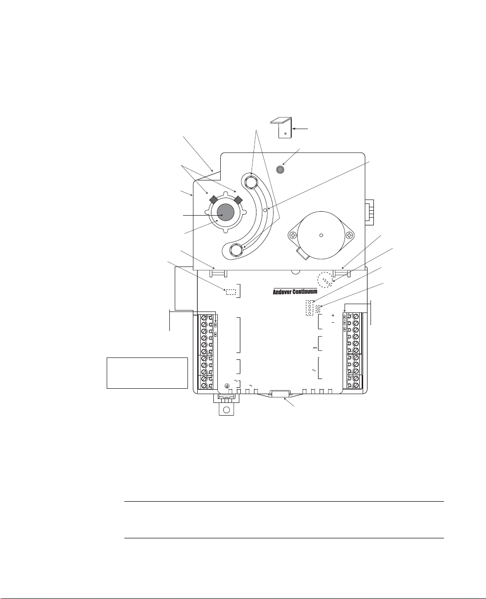
Chapter 1: Mechanical Installation
Alternative Damper Shaft
Mounting Screw Position
Damper Shaft
Hex Mounting Screws
Alternative Damper Shaft
Mounting Screw Position
Damper Shaft
Damper Shaft Collar
Cover Release
4-Position Dipswitch
Velocity Sensor
Inputs
(Barbed fittings)
Two CPU LEDs
Green = b3 controller
Yellow = i2 controller
Note: Input, Output, and
Smart Sensor connections will
vary per controller model.
Mounting Bracket
(LO)
(HI)
Adjustable Stops
Mounting Clip
Actuator Clutch Release
Damper Position Indicator
Alternate
Mounting Bracket
Cover Release
Battery Location
(Remove cover)
Service Port Location
P1
P2
(LOW)
AIR FLOW
INPUT
(HIGH)
IN11
2
IN2
3
RET
UNIVERSAL
INPUTS
4
IN3
5
IN4
6
RET
7
SPWR
SMART
8
RET
SENSOR
9
IN5
USE COPPER CONDUCTORS ONLY
24VAC
10
INPUT
24VAC , 0.42A, 10VA, 50/ 60HZ
11
866-V
CAUTION
MORE THAN ONE DISCONNECT SWITCH
MAY BE REQUIRED TO DE-ENERGIZE THIS
EQUIPMENT BEFORE SERVICING.
This equipment complies with part 15 of the FCC rules.
Operation is subject to the following two conditions.
(1) This device may not cause harmful interference.
(2) This device must accept any interference received,
including interference that may cause undesired
operation.
: CLASS 2 POWER ONLY
ANALOG
OUTPUTS
0-10VDC
DIGITAL
OUTPUTS
24VAC ,
RS-485
PORT
COM
21
COM
20
SHIELD
19
A07
18
RET
17
AO6
16
TRIAC REF
15
OUT5
14
OUT4
13
0.5A
OUT3
12
(Remove cover)
Jumper for Actuator
Direction
TD LED = Yellow
RD LED = Green
Wireless LED = Red
Cover Release
Step 1: Check the mounting location for the Andover Continuum i2 or
b3 865/866/885-V controller. The unit is typically mounted
with the controller extending down or to the right from the
damper shaft. However, the controller can be operated in any
position within the vertical plane.
Note: Installing the controller to the right (with the barbed fittings
pointing down) will help to prevent condensate from migrating
into the on-board velocity sensor.
i2/b3 865/866/885-V Controller Retrofit Guide 13
Page 14

Chapter 1: Mechanical Installation
With a downward extension, the available area around the
damper shaft must measure 6” (160 mm) down from the lower
edge of the shaft, 4.5” (120 mm) to the right, 1.5” (40 mm) to
the left and 1.75” (45 mm) above the shaft. Ensure the location
allows enough clearance for servicing.
The actuator is designed to mount over a
1
/2” (12.7 mm)
diameter shaft with a minimum of 2.5” (63.5 mm) of exposed
1
shaft. If the damper shaft diameter is less than
/2” (12.7 mm)
an adapter is required. An adapter (p/n AM-135) is available
3
from Schneider Electric to allow mounting on
/8” (9.5 mm)
damper shaft. The 865/866/885-V controller will not work with
larger damper shaft diameters.
Step 2: If the exposed damper shaft is less than 2” (51 mm) but at
least 1” (25.4 mm) long, move the two damper shaft mounting
screws to the alternate lower damper shaft positions (see
Figure 1).
Step 3: Select the mounting bracket location that will provide the
most stability for the operation of the actuator. Position the
mounting clip in the desired mounting bracket. Do not insert
the clip more than half-way into the bracket. This will allow
the clip and the back of the actuator to properly align with the
VAV box (see Figure 1).
Step 4: Rotate the VAV damper shaft by hand to the fully closed
position. Note whether the damper is rotated clockwise (CW)
or counter-clockwise (CCW) to close.
Step 5: Slip the controller over the damper shaft. Position the actuator
and, using a self tapping sheet metal screw, secure the
mounting clip to the VAV box.
14 Schneider Electric
Step 6: Press the actuator toward the box until the actuator comes
into contact with the VAV box, or the mounting clip snaps into
the bracket, or the back of the actuator comes into contact with
the VAV box.
tep 7: Press and hold the green actuator clutch release (see Figure 1)
S
and rotate the actuator collar to a nearly closed position, the 5°
index mark, if the damper shaft was rotated counter-clockwise
to close (Step 5). Rotate the actuator collar to the 85° index
Page 15

Chapter 1: Mechanical Installation
mark if the damper shaft was rotated clockwise to close
(Step 5).
Step 8: Tighten the two damper shaft hex mounting screws, using a
1
/8-inch Allen wrench. The minimum torque required to secure
the controller to the damper shaft depends on the shaft
material. The maximum torque for the socket screws is 30
inch-pounds (3.4 Nm).
Note: The damper should rotate freely when the clutch is released. If it
does not, the actuator may not be properly aligned with the
damper shaft – it may be necessary to repeat Steps 4 through 9
using a new orientation.
Step 9: If the damper does not provide a mechanical stop in the open
direction, or it is not desirable to use the damper’s open stop,
set the adjustable stops on the i2/b3 865/866/885-V controller
to the desired position. Use a
1
/4-inch hex driver to adjust the
screw stop on the controller.
Note: For the 866-V model only, the damper position feedback
reporting option can be enabled by changing the Andover
Continuum attribute, LCDState, from DISABLED to
ENABLED. The attribute, OverrideValue, indicates the
damper position as a fractional value from 0 (at the closed stop)
to 1 (at the open stop).
Note: The new 8xx-V controllers all use the same actuator jumper
settings to control the direction of the actuator motor. These
Tri-State settings are as follows:
Jumper Connected:
+ (On) = Clockwise (CW)
- (-On) = Counter Clockwise (CCW)
Off
Jumper Disconnected:
+ (On) = Counter Clockwise (CCW)
- (-On) = Clockwise (CW)
Off
i2/b3 865/866/885-V Controller Retrofit Guide 15
Page 16

Chapter 1: Mechanical Installation
Refer to the i2/b3 865/866/885-V Controller Installation Instructions
for additional information regarding the installation of your new “-V”
controller.
CAUTION
Connections
To complete the installation, you will need to make the correct power, input,
output and airflow connections. Although the location of the connections are
different between older and newer models, the only significant difference
is in the wiring required for the digital triac outputs. Continue to
Chapter 2 for more information and refer to the installation instructions
supplied with your controller.
Failure to observe this precaution can result in injury or equipment
damage.
16 Schneider Electric
Page 17

Chapter 2
Connections
This chapter describes the differences between the older generation
i2/b3 865/866/885 and TCX 865/866 VAV controllers and the newer
i2/b3 865/866/885-V controller’s connections.
Topics include:
z Power connections
z Universal Input connections
z Smart Sensor connections
z Digital Output connections
z Analog Output connections
z Airflow connections
Note: In addition to the information provided in these topics, please
refer to the i2/b3 865/866/885-V Controller Installation
Instructions when installing your new controller.
i2/b3 865/866/885-V Controller Retrofit Guide 17
Page 18

Chapter 2: Connections
I
:
CLASS
P
O
L
Y
V
AC , 0.
1
0
V
A, 5
0/6
0
S
Y
E
D
T
equipment
comeswith
art
ati
s
t
o
wing
t
w
p
p
e
vice
ayo
useha
gg
eece
)
T
e
vic
e
usta
c
ceptay
f
erenceceived
c
etata
c
a
d
operation
g
5
3
2
0
9
8
6
5
T
4
5
TRIA
RE
6
A0
E
3
2
3
5
6
890
W
O
T
5
T
0
0
T
,
0.5
A
O
1
)
2
)
Power Connections
Although the power connections for the older and newer controllers are
located in different places, they are clearly labelled and are all 24 VAC
connections.
The New i2/b3 8xx-V
Previous Generation
i2/b3 865/866 VAV
Power
P
P1
LO
(LO)
LO
(LOW)
P
P2
HIG
(HIGH)
HI
(HI)
IN11
2
IN2
2
3
RET
4
IN3
5
IN4
6
RET
7
8
RET
9
IN5
VA
24VAC
10
11
FL
AIRFLOW
INPUT
A
TIO
CAUTION
RTA
N
C
MORETHAN ONEDISCONNECT SWITCH
MAYBE REQUIREDTO DE-ENERGIZETHIS
EQUIPMENTBEFORE SERVICING.
UIPNTBOS
s
Thisequipment complies with part 15of the FCC rules.
on is
ot
efoll
Operation issubject to the following two conditions.
t ca
(1)Thisdevice may not cause harmful interference.
2
m
nter
(2)Thisdevice must accept any interference received,
includingnterferen
includinginterference that may cause undesired
operation.
UNIVERSAL
N
VER
A
INPUTS
SMART
SENSOR
E
USE COERCUTR
USE COPPERCONDUCTORS ONLY
NPUT
2
WER ON
INPUT
:
CLASS 2 POWER ONLY
A,
24VAC , 0.42A, 10VA, 50/60 HZ
866-V
ECTSWIT
VICIN
C
COM
21
oftheCes.
o conditions
nter
RS-485
-48
CO
COM
20
y
se undesre
PORT
HI
SHIELD
19
A07
18
ANALOG
RET
17
OUTPUTS
0-10VDC
O
AO6
16
TRIACREF
15
DIGITAL
O
OUT5
14
OUTPUTS
24VAC ,
OUT4
13
3
0.5A
OUT3
2
12
i2/b3 885 VAV
885
1
24VAC
0.42A,10VA
L
2
Power
Power
50/60HZ
USECOPPER
CONDUCTORSONLY
+
3
INFINET
-
4
PORT
5
SHIELD
6
3
OUT
DIGITAL
OUTPUTS
7
4
OUT
,0.5A
24VAC
8
GND
9
IN1
UNIVERSAL
10
RET
INPUTS
11
IN2
MODEL
S/N
DATE
INSTALLATION
For detailed instructions reviewdocument 30-3001-849 date
SERVICE
PORT
GND
+
-
MOTOR DIRECTION
Previous Generation
TCX 865/866 VAV
Power
18 Schneider Electric
Page 19

Chapter 2: Connections
New 8xx-V
Term inal
Locations
The power and ground connections for the i2/b3 8xx-V controllers are
located on the following terminals, which are labelled on each
controller.
Controller Power Terminal Ground Terminal
i2/b3 865/866-V 10 11
i2/b3 885-V 4 5
Universal Input Connections
The differences in the number of universal inputs and returns between
the older generation and the new “-V” controllers are listed in the table
below.
Controller Universal Inputs Returns
i2/b3 865/866-V 4 2
i2/b3 885-V 2 1
i2/b3 865/866 VAV 4 3
i2/b3 885 VAV 2 1
TCX 865 2 2 Returns and 1 Shield
TCX 866 3 2 Returns and 1 Shield
The i2/b3 865/866-V has a 4-position dipswitch with one switch per input and four
universal inputs. This switch enables and disables input pullup resistors.
Note:
You need to be aware of the differences between the old controller you
are replacing and the new one. For example, if you are replacing a TCX
865 with a new i2/b3 865-V controller, you have two additional input
connections available. If you are replacing an old i2/b3 865 VAV with
the new i2/b3 865-V, you only have two returns, instead of three, to
complete the circuits for the four universal inputs.
i2/b3 865/866/885-V Controller Retrofit Guide 19
Page 20
Chapter 2: Connections
New 8xx-V
Terminal
Locations
The universal input connections for the i2/b3 8xx-V controllers are
located on the following terminals:
Controller Universal Input
Terminal
i2/b3 865/866-V 1, 2, 4, 5 3, 6
i2/b3 885-V 3 1, 2
Return Terminals
Refer to the label on the controllers to identify the terminals.
20 Schneider Electric
Page 21

Smart Sensor Connections
The Andover Continuum Smart Sensor provides a display and a
multi-button programmable keypad that enables operators and
occupants to change setpoints, balance VAV boxes, monitor occupancy
status, and turn equipment on and off.
The controllers that have Smart Sensor inputs are listed in the table
below.
Chapter 2: Connections
New 8xx-V
Term inal
Locations
Controller Smart Sensor
Input
i2/b3 865/866-V 1 1 Return and 1 SPWR
i2/b3 885-V None
i2/b3 865/866 VAV 1 1 Return and 1 SPWR
i2/b3 885 VAV None
TCX 865 None
TCX 866 1 1 Return and 1 SPWR
Return and SPWR*
Connections
*Note: SPWR stands for Smart Power and refers to an Andover
Continuum Smart Sensor connection.
The Smart Sensor connections for the i2/b3 8xx-V controllers are
located on the following terminals:
Controller Smart Sensor
Input Terminal
i2/b3 865/866-V 9 8 - Return
i2/b3 885-V Not Available Not Available
Return and SPWR
Terminals
7 - SPWR
Refer to the label on the controllers to identify the terminals.
i2/b3 865/866/885-V Controller Retrofit Guide 21
Page 22

Chapter 2: Connections
Digital Output Connections
The differences in the number of digital outputs and returns between
the older generation and new “-V” controllers are listed in the table
below.
Controller Digital Outputs Triac Ref
i2/b3 865/866-V 3 1 Triac Ref
i2/b3 885-V 2 1 Triac Ref
i2/b3 865/866 VAV 3 Internally referenced to
i2/b3 885 VAV 2 Internally referenced to
TCX 865/866 3 (Isolated Floating
Outputs)
GND
GND
3 Isolated Returns
(NO - Normally Open)
New 8xx-V
Terminal
Locations
Note: The previous generation i2/b3 865/866/885 VAV controllers were
internally referenced to ground. The external GND terminals in
the Digital Output area are grounds for optional 24 VAC power
sources.
The digital output connections for the i2/b3 8xx-V controllers are
located on the following terminals:
Controller Digital Output
Terminals
i2/b3 865/865-V 12, 13, 14 15
i2/b3 885-V 6, 7 9
Triac Reference
Terminal
Refer to the label on the controllers to identify the terminals.
22 Schneider Electric
Page 23

How to Wire Digital Outputs
T
T
C
T
3
T
S
2VA
The one significant difference between the new and old controllers is
how the digital output connections need to be wired.
Chapter 2: Connections
New 8xx-V
Digital Outputs
AC Line
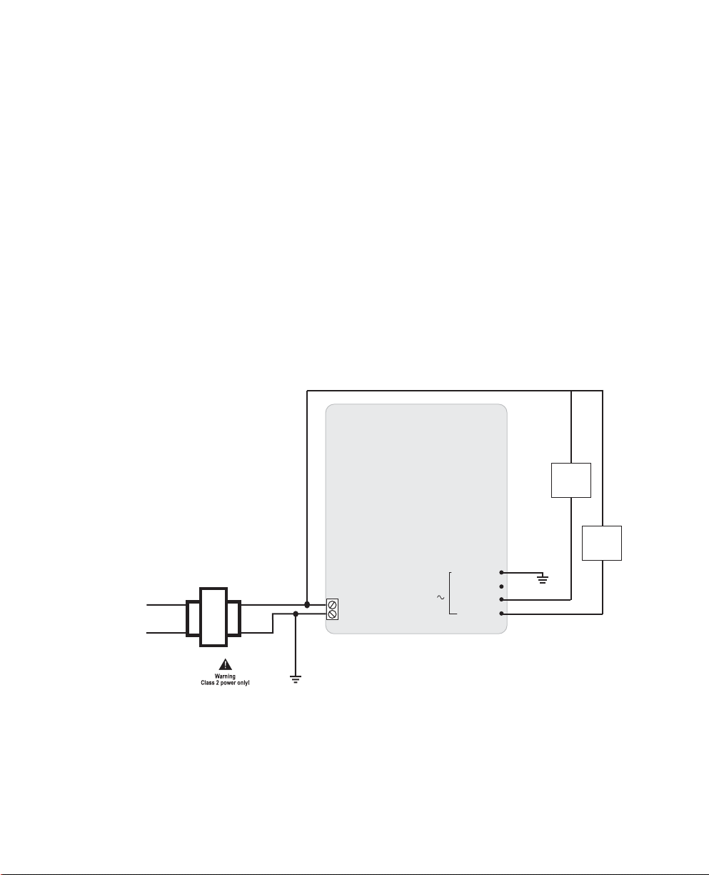
The new i2/b3 865/866-V controllers use three Form A triac output
terminals with a single triac reference. This configuration gives you the
flexibility to wire the single triac reference as either a hot or ground
connection. On these new controllers, all three outputs must be wired
the same, as either hot or ground switch applications.
To make a hot switch connection, connect one of the output terminals
(OUTX, where X = 3, 4, or 5) to a load, and connect the Triac Reference
to the incoming 24 VAC power.
Switching Option - Triac “Form A” Hot Connection
i2/b3 865/866-V Controller
24 VAC Step-Down
Power
Transformer
X1
X2
24 VAC
GND
DIGITAL
IGTAL
PUT
OUTPUTS
24VAC ,
0.5A
RIA
TRIAC REF
O
OUT5
OUT4
OUT3
15
5
14
T
13
12
Note: i2/b3 885-V Controller only has two digital outputs
i2/b3 865/866/885-V Controller Retrofit Guide 23
Page 24

Chapter 2: Connections
T
T
C
3
G
2VA
AC Line
Power
To make a ground switch connection, connect one of the output
terminals (OUTX, where X = 3, 4, or 5) to a load in series with the 24
VAC incoming power, and connect the Triac Reference to ground.
Switching Option - Triac “Form A” Ground Connection
i2/b3 865/866-V Controller
24 VAC Step-Down
Transformer
X1
X2
24 VAC
GND
Note: i2/b3 885-V Controller only has two digital outputs
DIGITAL
DI
TPUTS
OUTPUTS
24VAC ,
0
0.5A
RIA
TRIAC REF
OUT5
OUT4
OUT3
15
15
14
13
13
12
The new i2/b3 885-V controller, which only has two output terminal
connections, works the same, allowing for either two hot or ground
switch applications.
Old i2/b3
8xx-VAV Digital
Outputs
The previous generation of i2/b3 865/866-VAV controllers also used
three triac output terminals, but were internally referenced to ground
and cannot be wired as hot. All outputs are ground switch applications.
The old i2/b2 885-VAV controller used two output terminals that were
also internally referenced to ground and cannot be wired as hot.
Note: On the old i2/b3 865/866/885-VAV controllers, the external GND
terminals in the Digital Output area are grounds for optional 24
VAC power sources.
24 Schneider Electric
Page 25
Chapter 2: Connections
TCX 865/866
Digital Outputs
Form K Triac
Connections
Two product generations ago, the TCX 865/866 controllers also used
three triac output terminals, but allowed you to pair each output with
one of three isolated returns. This combination allowed you to create
either a hot or ground switch application for each individual output
load. The TCX controller could accommodate a combination of both hot
and grounded connections simultaneously.
All of the controllers, past and present, offer the ability to wire two of
the Form A outputs to create one Form K Tri-State output.
To create a Form K triac connection on the new i2/b3 865/866-V
controllers, make the individual connections from terminals 12 and 13
(OUT3 and OUT4), or use terminals 13 and 14 (OUT4 and OUT5), with
a common ground reference to terminal 15 (TRIAC REF).
Switching Option - Triac “Form K” Ground Connection
i2/b3 865/866-V Controller
OUT4
Load
AC Line
Power
OUT3
24 VAC Step-Down
Transformer
TRIAC REF
DIGITAL
X1
X2
24 VAC
GND
Note: i2/b3 885-V Controller only has two digital outputs
OUTPUTS
24VAC ,
0.5A
OUT5
OUT4
OUT3
15
14
13
12
Load
To maintain Form K triac connections on the new i2/b3 885-V
controller, make the individual connections from terminals 6 and 7
(OUT3 and OUT4) with a common ground reference to terminal 9
(TRIAC REF). Terminal 8 is not used on the 885-V controller.
i2/b3 865/866/885-V Controller Retrofit Guide 25
Page 26

Chapter 2: Connections
Rewiring Digital Outputs for an Old i2/b3 8xx-VAV Controller
Note: Since each generation of controller used a different internal
design for triac outputs and references, you need to pay close
attention to how the old controller you are replacing was wired.
If you are replacing a previous generation of i2/b3 8xx-VAV controller,
all the digital outputs for that generation of controller were referenced
to ground.
i2/b3 865/866 VAV Controller
i2/b3 885 VAV Controller
885
1
24VAC
0.42A,10VA
L
2
50/60HZ
USECOPPER
CONDUCTORSONLY
24VAC
MODEL
S/N
DATE
INSTALLATION
For detailed instructions reviewdocument 30-3001-849 date
SERVICE
+
3
PORT
INFINET
-
GND
4
+
PORT
-
5
SHIELD
6
3
OUT
DIGITAL
OUTPUTS
7
4
OUT
,0.5A
8
GND
9
IN1
UNIVERSAL
10
RET
INPUTS
11
IN2
MOTOR DIRECTION
Therefore, the simplest installation would be to make the following
ground switching connections when replacing the unit.
From the old i2/b3 865/866-VAV controller To the new i2/b3 865/866-V controller
OUT 3 (terminal 7) OUT3 (terminal 12)
OUT 4 (terminal 8) OUT4 (terminal 13)
OUT 5 (terminal 9) OUT5 (terminal 14)
GND (terminal 10 and 11) - Should not be
associated with Triac connections
From the old i2/b3 885-VAV controller To the new i2/b3 885-V controller
OUT 3 (terminal 6) OUT3 (terminal 6)
OUT 4 (terminal 7) OUT4 (terminal 7)
GND (terminal 8) - Should not be associated with
Triac connections
TRIAC REF (terminal 15)
TRIAC REF (terminal 9)
26 Schneider Electric
Page 27

Since the new i2/b3 8xx-V controllers are capable of both hot or ground
switching applications, you do have the option of rewiring all your
digital output connections to accomodate a hot switching application,
but this may cause problems with your existing circuits and loads.
For more information, refer to the hot switching diagram earlier in this
section, as well as the i2/b3 865/866/885-V Controller Installation
Instructions that came with the new controller.
Rewiring Digital Outputs for a TCX Controller
Chapter 2: Connections
Note: Since each generation of controller used a different internal
If you are replacing a previous generation TCX 865/866 controller, the
digital outputs and returns for that generation of controller were
individually isolated and permitted both hot and ground switching
application connections.
design for triac outputs and references, you need to pay close
attention to how the old controller you are replacing was wired.
TCX 865/866 VAV
Therefore, before replacing the unit and reconnecting the outputs, you
must understand how each output was wired. Since the replacement
i2/b3 8xx-V controller requires either all hot or all ground switch
connections, you may need to revise how some loads are wired to
complete the replacement installation.
i2/b3 865/866/885-V Controller Retrofit Guide 27
Page 28
Chapter 2: Connections
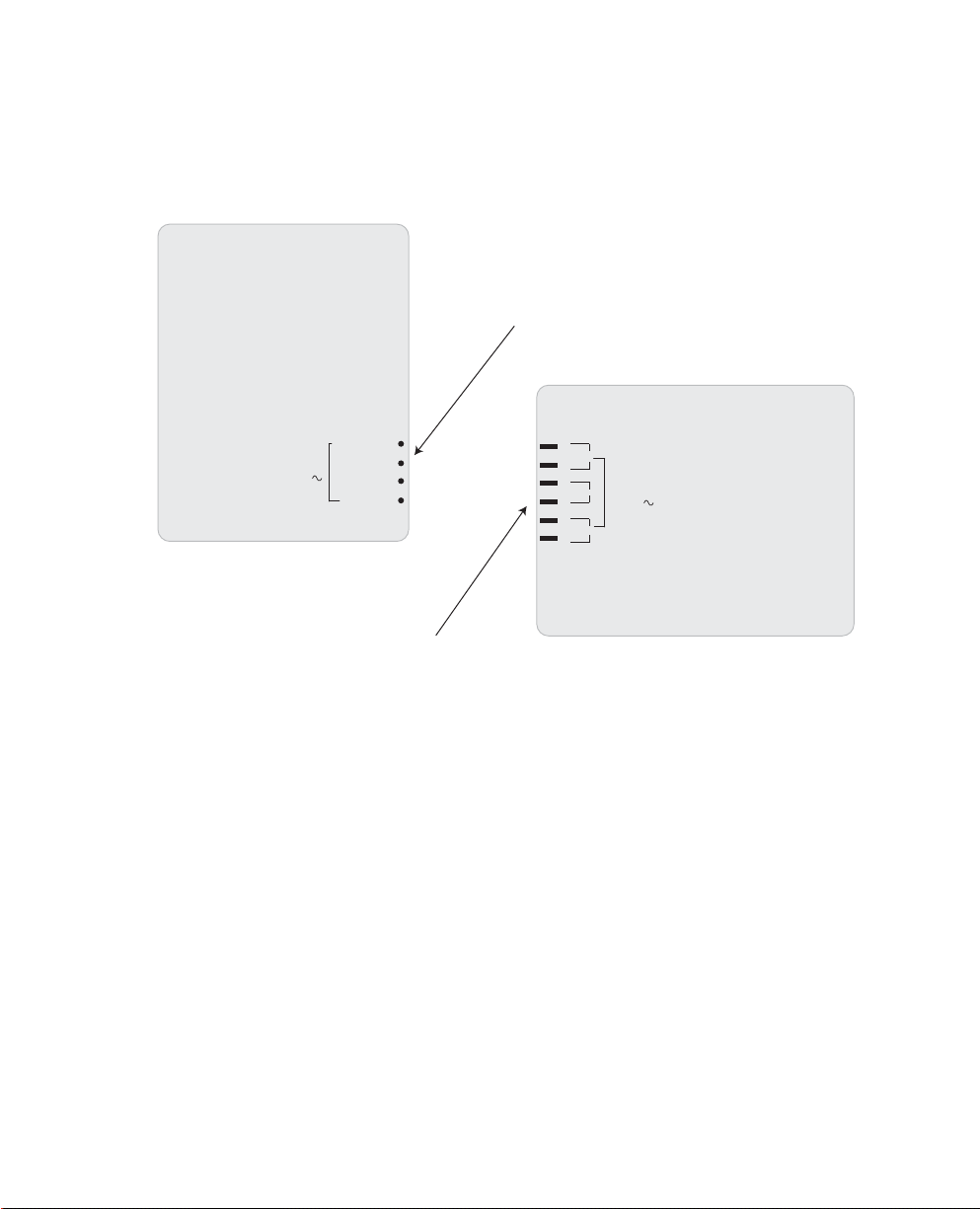
i2/b3 865/866-V Controller
The following illustration points out the differences in digital output
terminals for each controller.
Replacement
Three output terminals and one triac reference terminal
TCX 865/866 VAV Controller
TRIAC REF
DIGITAL
OUTPUTS
24VAC ,
0.5A
OUT5
OUT4
OUT3
15
14
13
12
OUT3
OUT4
OUT5
DIGITAL
OUTPUTS
24VA C ,
0.5 A
28 Schneider Electric
Three isolated output terminals and three isolated returns
for each connection
For more information refer to the hot and ground switching diagrams
earlier in this section, as well as the i2/b3 865/866/885-V Controller
Installation Instructions that came with the new controller.
Page 29

Analog Output Connections
The differences in the number of analog outputs and returns between
the older generation and the new “-V” controllers are listed in the table
below.
Controller Analog Outputs Returns
i2/b3 865-V None
i2/b3 866-V 2 1 Return
i2/b3 885-V None
i2/b3 865 VAV None
i2/b3 866 VAV 2 1 Return
i2/b3 885 VAV None
TCX 865 None
TCX 866 2 2 Return and 1 Shield
Chapter 2: Connections
New 8xx-V
Term inal
Locations
The analog output connections for the i2/b3 8xx-V controllers are
located on the following terminals:
Controller Analog Output
Terminals
i2/b3 865-V Not Available Not Available
i2/b3 866-V 16 and 18 17
i2/b3 885-V Not Available Not Available
Return Terminal
Refer to the label on the controllers to identify the terminals.
i2/b3 865/866/885-V Controller Retrofit Guide 29
Page 30

Chapter 2: Connections
Airflow Connections
The airflow sensors on both the old generation and the new “-V”
controllers have very similar connections, which include HI and LO
ports to match the HI and LO connections of the velocity sensor.
Airflow
Inputs
30 Schneider Electric
Note: Previous controllers required a micron filter component attached
to the HI hose connection. This is no longer required for the
i2/b3 8xx-V controllers.
Page 31

Page 32

i2/b3 865/866/885-V Controller Retrofit Guide
Document Number 30-3001-988
Revision D.1
 Loading...