

Page 1

Application
The AV-29x linkages are used to field assemble
Schneider Electric gear train hazardous location
actuators to VB-7xxx series or select VB-9xxx series
valve bodies.
Features
• Die cast aluminum mounting bracket.
• Valve position indication provided as standard.
AV-291, AV-293, AV-295, and
AV-296
Valve Linkage for
Hazardous Location Gear Train Actuators
General Instructions
Applicable Literature
• EN-56-2 Apparatus for Use in Hazardous Locations,
F-
18451
• MAx-305 & MAx-318 Series MAx-405 through
MAx-
419 Series, Two-Position Actuators Genera
Instruc
tions, F-06491
• MC-351, 421, 431, MC-4311 Three-Wire, Two
Position
• MP-3xx and MP-4xx Series Reversible and
Proportional Electric
• Valve Products Catalog, F-27384
• EN-205 Water System Guidelines, F-26080
Actuators General Instructions, F-08366
Actuators, F-15479
l
Printed in U.S.A. 4/10 © Copyright 2010 Schneider Electric All Rights Reserved. F-27441-2
Page 2
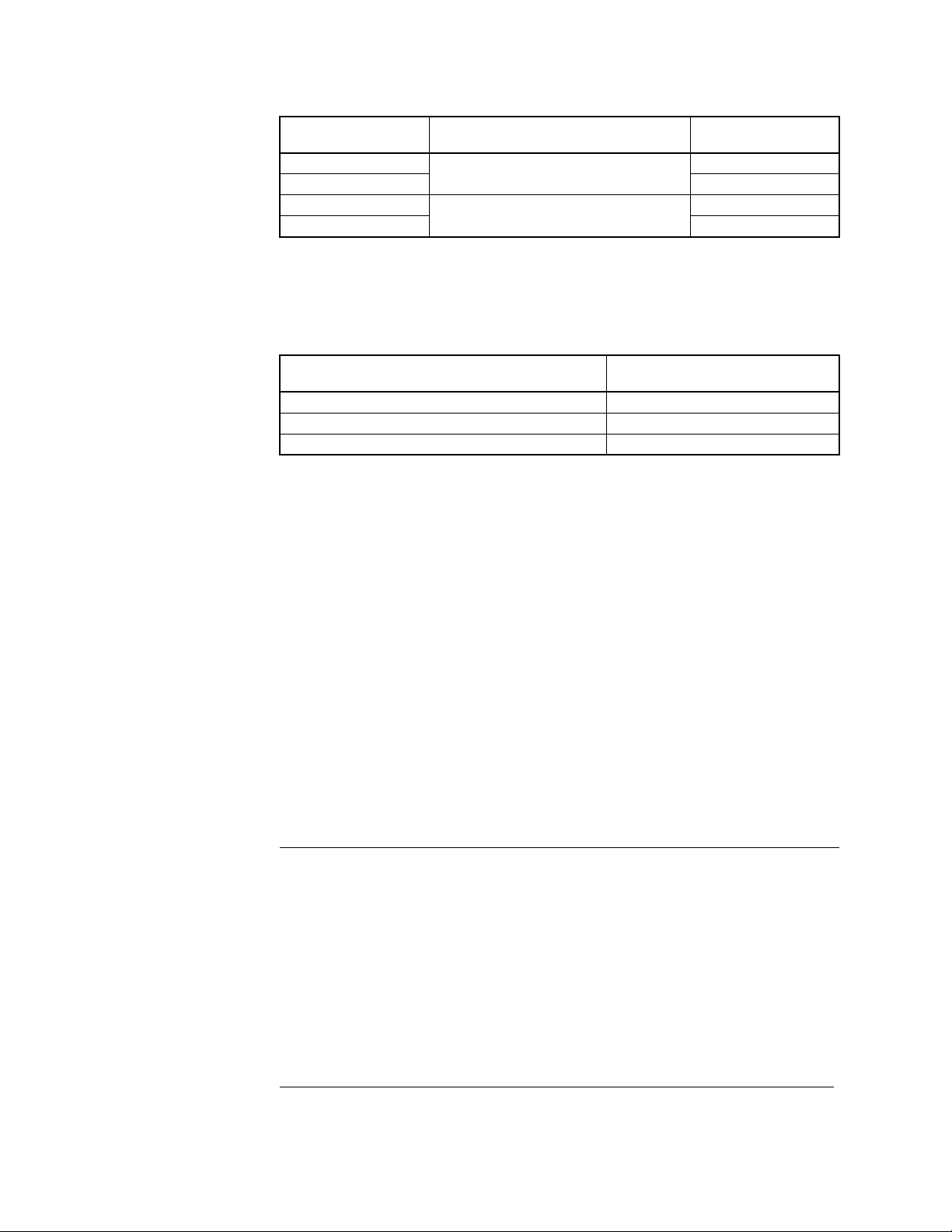
SPECIFICATIONS
Table-1 Model Chart.
Required Components
Valve Linkage
Model Number
AV-291
AV-293 300
AV-295
AV-296 300
VB-9313 2
Description
Complete Linkages
VB-7xxx 1/2” to 2”
VB-9xxx 2-1/2” to 3” bronze
-1/2” to 4” cast iron flanged
Stem Force
(lb.)
150
150
Temperature Restrictions
Verify that the fluid temperature of the media in the valve versus the ambient temperature at
the actuator does not exceed the ratings shown in Table-2.
Table-2 Restrictions on Maximum Ambient Te m pe r ature for Actuators.
Maximum Temperature of Media in the Valve
(Check Rating of Valve) °F (°C)
260 (126) 136 (57)
281 (138) 125 (52)
300 to 366 (149 to 185) 100 (37)
Maximum Ambient for Actuator
°F (°C)
Close-off Pressure Rating
Close-off pressure ratings are listed in Table-3. Check the appropriate table to verify that the
selected valve, valve linkage,
application.
The actuator with hazardous location housing, valve, and valve linkage should be purchased
separately. See Table-3 for selections.
and actuator provide adequate close-off pressure for your
INSTALLATION
Inspection Inspect the package for damage. If damaged, notify the appropriate carrier immediately.
If undamaged, open the package and inspect the device for obvious damage. Return
damaged products.
Requirements • Tools (not provided):
– Appropriate wrenches for stem extensions, lock nuts, packing nuts, and brackets
– Appropriate screwdriver for actuator mounting screws
– TOOL-37, 1-5/8" open-ended wrench with a ma
• Training: Installer must be a qualified, experienced technician
Caution:
• Install the unit in accordance with the National Electric Code Article 500 and all
applicable local codes.
• Avoid locations where excessive moisture, corrosive fumes, or vibration is present.
• Install all two-way valves so that they close against the flow. An arrow on the valve body
or a tag indicates the proper flow direction.
• Always install three-way mixing valves with two inlets and one outlet.
• Always install three-way diverting valves with one inlet and two outlets.
• The actuators can be mounted in any position above the centerline of the valve body.
For steam applications where the ambient temperature approaches the limit of the
actuator, the valve stem should be mounted 45° from vertical. When selecting a
location, allow sufficient room for accessories and for service of the product.
ximum thickness of 3/16"
2 © Copyright 2010 Schneider Electric All Rights Reserved. F-27441-2
Page 3
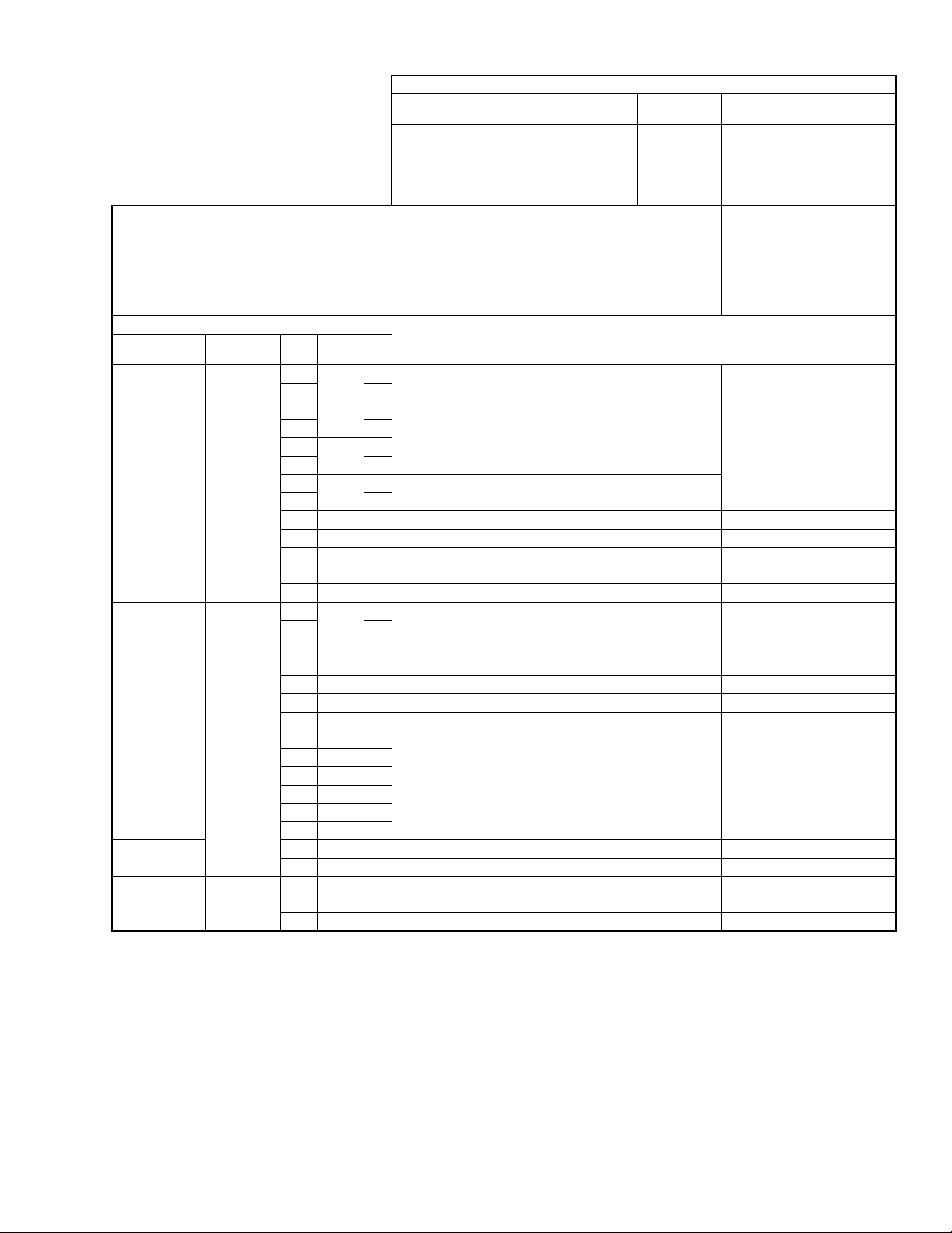
Table-3 Linkage Selection and Valve Close-Off Pressure Ratings for VB-7x xx and VB-9x1x Valve Bodies.
TYPICAL ACTUATOR PART NUMBERS
Spring Return No Normal
MA8-318, MA8-318-500
MA8-418, MA8-418-500
MP6-361, MP6-367
MP6-371, MP6-377, MP6-379,
MP6-465 MP7-4651
MP6-470, MP6-475, MP7-4751
Minimum Torque/Travel Required
Linkage for 1/2" to 2” VB-7xxx Series Valves AV-291 AV-293
Linkage for 2-1/2" to 3" VB-9xxx Series Bronze Body
Linkage for 2-1/2" to 4" VB-9313 Cast Iron Body
VALVE BODY INFORMATION CLOSE-OFF PRESSURE PSI (kPa)
Valve Body
t Number
Par
VB-7213-0-4-P
VB-7214-0-4-P
VB-7215-0-4-P
VB-7253-0-4-P
VB-7273-0-4-P
VB-9213-0-4-P
VB-9215-0-4-P
VB-7313-0-4-P
VB-7314-0-4-P
VB-7315-0-4-P
VB-7323-0-4-P
VB-9313-0-4-P
VB-9315-0-4-P
VB-9313-0-5-P
a
See Table-4 to set stem and cam position.
Description P
2-Way
3-Way
3-Way
125 lb
F
langed
Code
1
2 1.3
3 2.2
4 4.4
5
6 7.5
7
8 14
9 1-1/4" 20 90 (621) 200 (1379)
10 1-1/2" 28 65 (448) 140 (965)
11 2" 40 35 (241) 80 (552)
12 2-1/2" 65 20 (137) 50 (345)
13 3" 85 12 (83) 34 (234)
2
6 3/4" 7.5 220 (1517)
8 1" 14 150 (1034) 250 (1724)
9 1-1/4" 20 100 (689)
10 1-1/2" 28 60 (414) 140 (965)
11 2" 41 33 (228) 80 (552)
10 1-1/2” 28
11 2” 40
12 2-1/2" 67 20 (137) 50 (345)
13 3" 91 12 (83) 34 (234)
12 2-1/2" 74 20 (137) 50 (345)
.
13 3" 101 12 (83) 34 (234)
14 4" 170
4 1/2” 4.4
6 3/4” 7.5
8 1” 15
9 1-1/4” 20
lves
Va
Va
lves
Size Cv
0.4
1/2"
5.5
3/4"
10
1"
2.2
1/2"
50 lb.-in., 180° Rotation,
Plunger
150 lb.
AV-295 AV-296
–
250 (1724)
150 (1034)
250 (1724)
250 (1724) 250 (1724)
6 (41) 17 (117)
Posi
tion
MP6-421 MC6-351
a
No Normal Position
MC6-421
MC6-431
MP6-381
MP6-485
MC7-4311
175/220 lb.-in., 180° Rotation,
300 lb. Plunger
250 (1724)
250 (1724) 4 4.4
200 (1379)
F-27441-2 © Copyright 2010 Schneider Electric All Rights Reserved. 3
Page 4

ASSEMBLY PROCEDURE
Indicator Screw
BYRF-105
Front Cover
ADDA-880-1
Nylon Bushing
AYRD-405
Mxx-xxx Hazardous Location Actuator
Mounting Screws (3)
BYRF-2286
Mounting Bracket
NYBA-61
Valve Body
Plunger Assembly
Connecting Pin
ADFA-20-1
Stem Extension
NYBA-37
Stem Locknut
YBA-519-1
Packing Nut
Mounting Nut
Cover Screws (2)
BYRF-695
Indicator
ADDA-9-2
Plunger Cam
NYBA-77
1
1
1
1 Not included in AV kits.
2 ADDA-104-002 (150 lb.)
FYBA-53-9 (300 lb.)
2
1
AV-291 and AV -293 Note: Position the bracket on the valve in such a way as to make it convenient to wire the
actuator.
Valve Linkage for 1/2" to 2" VB-7xxx
1. Mount the bracket on the valve body by screwing the mounting nut into the mounting
bracket. Tighten the hex mounting nut, using a 1-5/8" open-ended wrench with a
maximum thickness of 3/16" (TOOL-37). See
Valve Linkage Common Procedure on page 6.
Figure-1. Proceed to step 2 in AV29x
Figure-1 Valve Linkages for 1/2" to 2" VB-7xxx.
4 © Copyright 2010 Schneider Electric All Rights Reserved. F-27441-2
Page 5

A V-295 and AV-296 on Valve Bodies
Valve Linkage for Current 2-1/2” to 4” VB-9x1x
1. Mount the bracket onto the valve body by removing the bracket nut, placing the bracket
on the valve body, and replacing and tightening the valve bracket nut. See Figure-2.
Proceed to step 2 in AV29x Valve Linkage Common Procedure on page 6.
Indicator
ADDA-9-2
Indicator Screw
BYRF-105
Cover Screws (2)
BYRF-695
Front Cover
ADDA-880-1
Nylon Bushing
Plunger Assembly
Plunger Cam
AYRC-44-2
Connecting Pin
ADFA-20-1
Mxx-xxx Hazardous Location Actuator
1
AYRD-405
2
Mounting Bracket
NYBA-68
Stem Extension
NYBA-37
Mounting Screws (3)
BYRF-2286
Threaded VB-9xxx Valve Body
2-1/2" and 3"
Figure-2 Valve Linkages for Current 2-1/2" to 4" VB-9313 Cast Iron Flanged,
Stem Locknut
DYRF-11
Packing Nut
Bracket Nut
1
and VB-9xxx
1
1
2-1/2” to 4”
Flanged VB-9313 V
alve Body
1
2-1/2” and 3” Threaded Bronze Valve Bodies.
1 Not included in AV kits.
2 ADDA-104-002 (150 lb.)
FYBA-53-9 (300 lb.)
F-27441-2 © Copyright 2010 Schneider Electric All Rights Reserved. 5
Page 6

AV29x Valve Linkage
Full CW Position
Full CCW Position
Short Tooth on
Actuator Shaft
at 9:00
Short Tooth on
Actuator Shaft
at 3:00
Common Procedure
The following steps are common to all AV-29x valve linkages. Perform step 1 on page 4 or
5 before proceeding to step 2.
2. Thread the stem lock nut and stem extension down fully onto the valve stem.
3. Place the actuator onto the mounting bracket. Fasten the actuator to the mounting
bracket with the three mounting screws, BYRF-2286. Do not tighten the screws.
4. Place the nylon bushing onto the actuator shaft.
5. Position the actuator to the 3:00 (CW) or 9:00
up or down as required. Use Figure-3 and Table-4.
Table-4 Actuator Shaft and Cam Position.
Actuator
Shaft
Position
Valve Position Cam/Valve Position Valve Position Cam/Valve Position
(CCW) position so that the cam is pointing
Figure-3 Actuator Shaft Position (Front View).
CW
Short tooth on
shaft
actuator
at 9:00
CCW
Short tooth on
shaft
actuator
at 3:00
VB-7213 (closed)
VB-7313 (B closed)
VB-7323 (B to A open)
VB-921x (closed)
VB-931x (B closed)
VB-7213 (open)
VB-7313 (A closed)
VB-7323 (B to AB open)
VB-921x (open)
VB-931x (A closed)
6. Consult Table-5 for the proper cam. Place the cam in the plunger and slip the plunger
VB-7213 (open)
VB-7313 (A closed)
VB-7323 (B to AB open)
VB-921x (open)
VB-931x (A closed)
Cam Down
Cam Up
VB-7213 (closed)
VB-7313 (B closed)
VB-7323 (B to A open)
VB-921x (closed)
VB-931x (B closed)
cam onto the actuator shaft with the cam po
Cam Up
Cam Down
inting to the required position.
6 © Copyright 2010 Schneider Electric All Rights Reserved. F-27441-2
Page 7

Table-5 Cam Selection.
Use Cam
Marked
77 AV-291 and AV-293 1/2" to 2" VB-7xxx 1/2"
44-2 AV-295 and AV-296 2-1/2" to 4" VB-9xxx 1"
Included in Linkage Kits For These Valve Bodies
With
minal
No
Stroke
7. Push the valve stem completely down.
8. Screw the stem extension until the hol
es in the stem extension and plunger line up.
9. Turn the stem extension upward, counterclockwise, into the plunger 2 full turns.
10. Raise the actuator up until the connecting pin can be inserted through the holes in the
plunger and stem extension.
1 1 . Tighten the actuator mounting screws.
12. Tighten the stem lock nut agai
nst the stem extension.
13. Place the front cover over the plunger assembly and fasten it to the actuator with two
cover screws, BYRF-695.
14. Install the position indicator to the end of the actuator shaft. See Table-4 for the correct
position.
F-27441-2 © Copyright 2010 Schneider Electric All Rights Reserved. 7
Page 8

CHECKOUT
Check to assure correct plunger spring compression. The length of the stem extension
should be adjusted so that the valve disc seats before the actuator reaches the end of the
stroke. The balance of the actuator stroke is taken up in the plunger spring compression,
which should be approximately 1/16 inch (1.6 mm). This applies pressure on the disc in the
closed position(s) and compensates for disc and seat wear. Refer to Figure-5 for VB-7213
(stem down closed). For three way applica
tions (VB-73x3 or VB-9313) refer to Figure-4
andFigure-5.
VB-7213 Example 1. Drive the actuator so the valve stem is fully down.
2. Observe the plunger spring compression as in Figure-5.
VB-7313 Example 1. Drive the actuator so the valve stem is fully up.
2. Observe the plunger spring compression as in Figure-4.
3. Drive the actuator so the valve stem is fully down.
4. Observe the plunger spring compression as in Figure-5.
Plunger Spring
Housing
Spring Compression
Approximately 1/16” (1.6 mm)
Spring Compression
Connecting Pin
Stem Extension
Stem Locknut
Plunger Spring
Housing
Connecting Pin
Stem Extension
Valve Seat Contact
Valve Stem
Figure-4 Valve Compression Stem Up.
Spring Compression
Approximately 1/16” (1.6 mm)
Valve Seat Contact
Valve Seat Compression
Stem Locknut
Valve Stem
Figure-5 Valve Compression Stem Down.
8 © Copyright 2010 Schneider Electric All Rights Reserved. F-27441-2
Page 9

MAINTENANCE
Allow 12” (300) minimum service clearance above the housing top.
O
P
E
N
C
L
O
S
E
D
8-1/4 (209)
4-1/8 (105)
4-1/2
(114)
7
(178)
9
(228)
Coupling Line
for Actuator
1/4
(6)
1-1/4 – 16 Threads
(AV-291 and
A
V-293 only)
Dimensions shown
are in inches (mm).
4-1/4 (108)
Coupling Line
for Valve Body
5-7/16
(139)
7-7/8 (200)
DIMENSIONAL DATA
Regular maintenance of the total system is recommended to assure sustained optimum
performance.
Figure-6 Front Dimensions.
F-27441-2 © Copyright 2010 Schneider Electric All Rights Reserved. 9
Page 10

On October 1st, 2009, TAC became the Buildings business of its parent company Schneider Electric. This document reflects the visual i denti ty of Schn eider Elec tric,
ho wever there rem ains r eferences to TAC as a corpor a te br and in the body copy. As each document is updated, the body copy will be c han ged to reflect appropriate
4-1/2
(114)
2-15/16
(51)
2-1/8
(54)
3/4 (19) Pipe Tap
On Each Side
9
(229)
10-13/16
(275)
1/8
(3)
1-1/4 (32)
5/8 (16)
Dimensions shown
are in inches (mm).
Figure-7 Side Dimensions.
corporate brand changes.
Copyright 2010, Schneider Electric
All brand names, trademarks and registered
trademarks are the property of their respective
owners. Information contained within this
document is subject to change without notice.
F-27441-2
 Loading...