

Page 1
The essential guide
of Automation
& Control
2011
Page 2

The go to guide
for the most efficient selection
Make the most of your energy
Page 3

Contents
Detection
p Photo-electric, inductive and ultrasonic sensors
p Limit switches
p Sensors for pressure control
p Rotary encoders and radio frequency identification
Operator dialog
p Control and signalling units
p Human/Machine Interfaces
Automation
p Relays
p Programmable controllers
p Automation platforms
p Configuration software
Motion and Drives
p Soft starters and variable speed drives
p Servo drives, Servo motors and Motion controllers
p Stepper drives and motors, integrated drives
p Linear motion axe and Multi-axis systems
1
2
3
4
Motor control
p Motor control components
p Components for power control applications
Power supplies
p Power supplies
p Transformers
p Connection
Interfaces and I/O
p Distributed Inputs/Outputs
p Interfaces
p Accessories and Cabling
Networks connectivity and Web servers
p
ConneXium cabling system
p
AS-Interface cabling system
p
Servers and Gateways
Machine safety
p Safety solutions provide maximum protection in all the safety
functions of your automation system
5
6
7
8
9
Explosive atmospheres
p Detection
p Operator dialog
p Machine safety
p Automation
10
Page 4
Innovative and simple products for all Auto
m
Interfaces & I/O
Connectors
Cable-ends, terminal blocs
Interfaces
Plug-in relays, analog
converters, discrete
interfaces
Pre-wired interfaces,
IP20/IP67 distributed I/O
AS-Interface
IP20/IP67 interfaces,
cables, repeaters,
accessories,adressing and
adjustment terminals
Machine safety
Safety monitors and
controllers on AS-Interface
Software
Software to design and
install AS-Interface system,
safety monitors and
controllers on AS-Interface
programming software
Mounting systems
Enclosures
Wall mounted enclosures
Floor standing enclosures,
suite type cubicles
Industrial boxes
Equipment and accessories
Thermal control equipment
Power splitter blocks
Mounting accessories
Power supplies
Power supplies
Switch mode power
supplies
Filtered rectified power
supplies, transformers
AS-Interface
Power supplies
Automation
Relays
Plug-in relays, electronic
timers, control relays,
counts
Smart relays
PLCs, PC based control,
distributed I/O
Programmable controllers
PLC platforms
PC based control
Distributed I/O, I/O
controllers
AS-Interface
Master modules for
Modicon PLCs
Machine safety
Safety PLCs, controllers
and modules
Software
PLCs and safety controllers
programming software
Systems &
Architectures
Connecting Ethernet
devices
Web-enabling PLCs
on Ethernet
Application protocols
and field buses
Page 5
ation and Control functions
Motion & Drives
Soft starters, drives
and linear axes
Soft starters
Variable speed drives
Motion controllers
Servo drives and motors
Stepper drives and motors
Integrated drives
Single axes and multi-axis
systems
Software
Setup and Programming
software
Motor control
Motor starters
Contactors
Circuit breakers, fuse carriers
Thermal relays
Combinations,
motor controllers
Mounting solutions
Motor starter mounting kit
AS-Interface
Motor controllers,
enclosures, variable speed
drives
Machine safety
Switch disconnectors,
thermal-magnetic motor
circuit breakers, enclosed
starters
Software
Motor control programming
software
Software tools
Global software
Generation of application
systems
Application control
Collaborative development
Dedicated software
See Software in other
functions
Operator dialog
Control & signalling units
Control and signalling units,
Cam switches,
Beacons and indicator banks
Human machine interfaces
Operator interface terminals,
industrial PCs, Web servers,
HMI and SCADA PC-based
software
Control stations, mounting
solutions
Control and pendant stations,
front panels mounting kits
AS-Interface
Control stations, keypads,
beacons
Machine safety
Emergency stops, control
stations, enabling switches,
foot switches
Software
Operator terminal software
Detection
Sensors
Limit switches
Proximity sensors
Photo-electric and ultrasonic
sensors
Pressure switches
Rotary encoders
RFID
Inductive identification
Machine safety
Switches, light curtains,
mats
Software
Safety mats configuration
software
Page 6

With monitoring, counting and control
expertise built into its limit switches,
sensors, rotary encoders and RFID
solutions, Schneider Electric has a
wide range of products to meet all
your detection needs, making it easy
for you to choose, procure, install and
maintain your products.
OsiSense
OsiSense is the range name for all
Schneider Electric’s detection products.
Page 7

Detection
This document is a selection of
the top selling products.
Limit switches .....................................................................................................................................1/2 to 1/11
Detection by contact of rigid objects
Object speed ≤ 1.5 m/s, OsiSense XC
1
2
Sensors for pressure control ................................................................................................... 1/12 to 1/17
Detection by contact with fluid
Electronic or electromechanical pressure and vacuum switches,
pressure sensors, OsiSense XM
Inductive proximity sensors ...................................................................................................... 1/18 to 1/28
Detection without contact of metal objects
Sensor / object distance ≤ 60 mm, OsiSense XS
Capacitive proximity sensors .............................................................................................................. 1/29
Detection of insulating materials or conductive materials
Specific products for particular applications, OsiSense XT
Photo-electric sensors .................................................................................................................. 1/30 to 1/41
Detection without contact of any object
Detection from a few millimetres to several tens of metres, OsiSense XU
Ultrasonic sensors ........................................................................................................................ 1/42 and 1/43
Detection without contact of any object of any material
Detection from a few millimetres up to 8 metres, OsiSense XX
3
4
5
6
7
Rotary encoders ............................................................................................................................... 1/44 and 1/45
Opto-electronic detection
Incremental or absolute - single turn and multiturn, OsiSense XCC
Radio frequency identification ............................................................................................. 1/46 and 1/47
13.56 MHz RFID detection
Complete range of RFID tags and compact stations, OsiSense XG
Sensors for explosive atmospheres
See chapter 10 “Explosive Atmospheres”
8
9
10
1/1
Page 8
13
14
22
21
BK
WH
BK
BU
BN
GN-YE
BK
WH
BK
BU
BN
GN-YE
13
14
22
21
1314
22
21
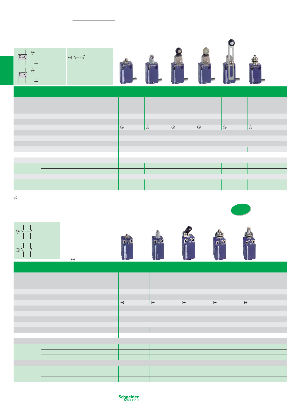
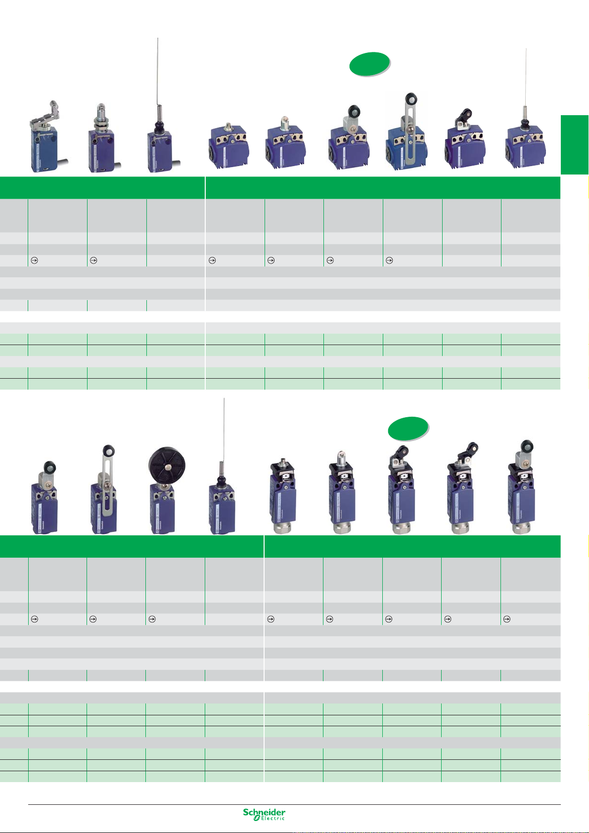
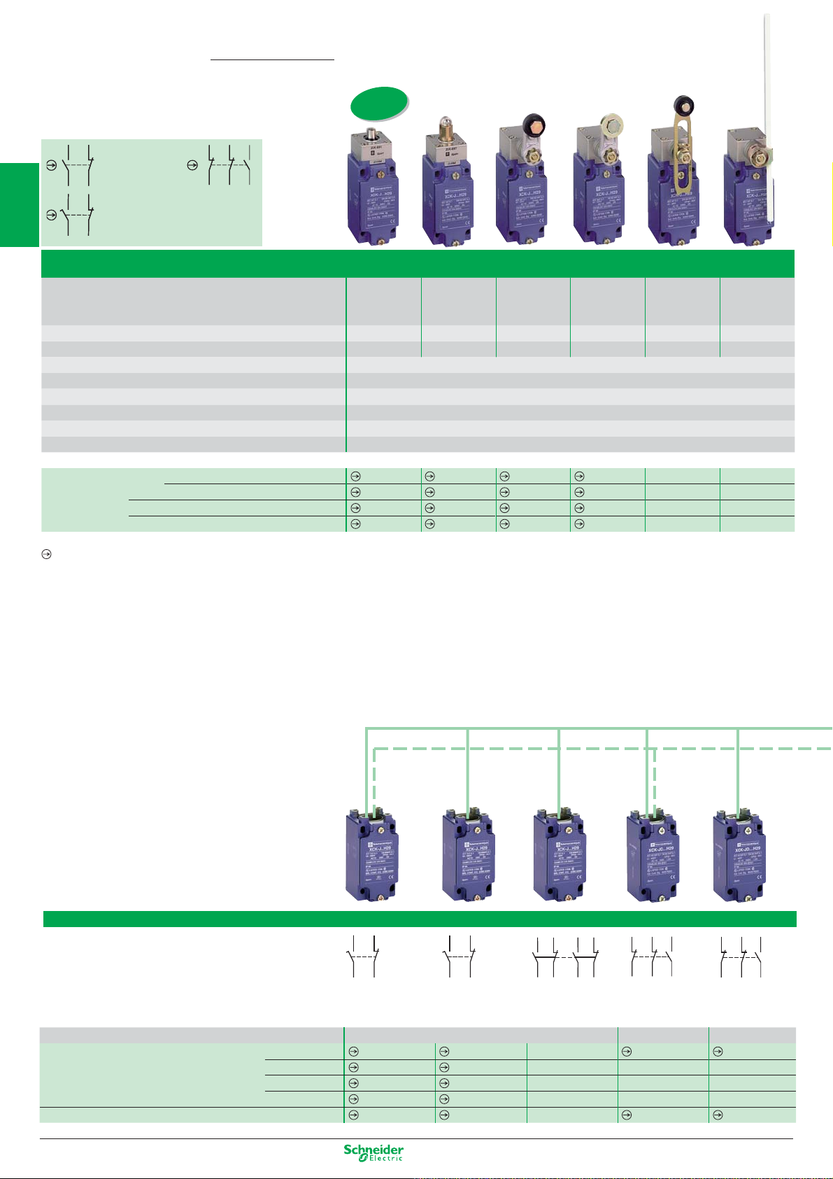
OsiSense XC
Limit switches
Compact and miniature, complete switches
(variable composition, see pages 34-35)
1
XCMD
2-pole contact
NC+NO
snap action
2-pole contact
NC+NO
slow break
XCKT
2-pole contact
NC+NO
snap action
Miniature XCMD metal, pre-cabled; fi xing by the body or by the head
Type of operator Metal
2
Mechanical durability (millions of operating cycles) 10 10 10 10 10 10
Actuation speed (in m/s) 0.5 0.5 1.5 1.5 1.5 0.5
Switches conforming to standard IEC 947-5-1 section 3
Product certifi cation CE - UL - CSA - CCC
3
Degree of protection conforming to IEC 60529 IP 66 and IP 67
Rated operational characteristics AC-15; B300 (Ue = 240 V, Ie = 1.5 A) / DC-13; R300 (Ue = 250 V, Ie = 0.1 A)
Fixing centres (mm) 20 M12 x 1
Body dimensions (mm) W x D x H 30 x 16 x 50
Connection Cable Pre-cabled, adjustable direction, length = 1 m (other lengths available on request)
Complete switch 2-pole NC+NO snap action XCMD2110L1 XCMD2102L1 XCMD2115L1 XCMD2116L1 XCMD2145L1 XCMD21F0L1
4
Complete switch NC+NO snap action (M12-5 pins) XCMD2110C12 XCMD2102C12 XCMD2115C12 XCMD2116C12 XCMD2145C12 XCMD21F0C12
(1) Although their design is identical to the pre-cabled switches, the switches incorporating an M12 4-pin connector cannot be marked with the symbol because they are single-pole C/O.
Positive opening operation.
2-pole NC+NO break before make, slow break XCMD2510L1 XCMD2502L1 XCMD2515L1 XCMD2516L1 XCMD2545L1 XCMD25F0L1
Connector M12
1C/O snap action (M12-4 pins) (1) XCMD2110M12 XCMD2102M12 XCMD2115M12 XCMD2116M12 XCMD2145M12 XCMD21F0M12
end plunger
Steel roller
plunger
Thermoplastic
roller lever
Steel
roller lever
Variable length
thermoplastic
roller lever
M12 head
metal
end plunger
5
ISO entry
to EN 50262)
(
XCKP/XCKD
2-pole contact
NC+NO
snap action
6
2-pole contact
NC+NO
slow break
Positive opening operation.
Compact XCKD metal and XCKP plastic conforming to standard EN 50047
7
Type of operator Metal
Mechanical durability (millions of operating cycles) 15 10 15 10 10
Actuation speed (in m/s) 0.5 0.5 1 0.5 0.5
8
Switches conforming to standard IEC 947-5-1 section 3
Product certifi cation CE - CSA - CCC - GOST
Degree of protection conforming to IEC 60529 IP 66 and IP 67
Rated operational characteristics AC-15; A300 (Ue = 240 V, Ie = 3 A) / DC-13; Q300 (Ue = 250 V, Ie = 0.27 A)
Cable entry 1 tapped entry for ISO M16 x 1.5 cable gland (3) or M12 connector
Fixing centres (mm) 20 20 20 M18 x 1 M18 x 1
9
Body dimensions (mm) W x D x H 31 x 30 x 65
Metal switches
Complete switch 2-pole NC+NO snap action XCKD2110P16 XCKD2102P16 XCKD2121P16 XCKD21H0P16 XCKD21H2P16
2-pole NC+NO break before make, slow break XCKD2510P16 XCKD2502P16 XCKD2521P16 XCKD25H0P16 XCKD25H2P16
2-pole NC+NO snap action (M12-5 pins) XCKD2110M12 XCKD2102M12 XCKD2121M12 XCKD21H0M12 XCKD21H2M12
10
Plastic, double insulated switches
Complete switch 2-pole NC+NO snap action XCKP2110P16 XCKP2102P16 XCKP2121P16 XCKP21H0P16 XCKP21H2P16
(3) For Pg 11 cable entries, replace P16 by G11. Example: XCKD2110P16 becomes XCKD2110G11.
For other cable entries, see customised assembly on page 1/34.
1/2
2-pole NC+NO break before make, slow break XCKP2510P16 XCKP2502P16 XCKP2521P16 XCKP25H0P16 XCKP25H2P16
2-pole NC+NO snap action (M12-4 pins) XCKP2110M12 XCKP2102M12 XCKP2121M12 XCKP21H0M12 XCKP21H2M12
end plunger
Steel
roller plunger
Thermoplastic
roller lever plunger,
horizontal actuation
in 1 direction
Other versions: please consult our Customer Care Centre.
M18 head
metal
end plunger
M18 head
steel
roller plunger
Page 9
Compact XCKT plastic, 2 cable entries
ISO entry
to EN 50262)
(
1
Retractable
steel roller lever
plunger
10 105 151010155 5
0,5 0.1 1 0.5 0.5 1.5 1 1 1
20 M12 x 1 20 20 or 40
XCMD2124L1 XCMD21F2L1 XCMD2106L1 XCKT2110P16 XCKT2102P16 XCKT2118P16 XCKT2145P16 XCKT2121P16 XCKT2106P16
XCMD2524L1 XCMD25F2L1 XCMD2506L1 – –––––
XCMD2124C12 XCMD21F2C12 XCMD2106C12 – –––––
XCMD2124M12 XCMD21F2M12 XCMD2106M12 – –––––
M12 head
steel
roller plunger
“Cat’s whisker” Metal
–
end plunger
CE - CSA - CCC - GOST
IP 66 and IP 67
AC-15; A300 (Ue = 240 V, Ie = 3 A) / DC-13; Q300 (Ue = 250 V, Ie = 0.27 A)
58 x 30 x 51
2 tapped entries for ISO M16 x 1.5 cable gland (2)
(2) For Pg 11 cable entries, replace P16 by G11. Example: XCKT2110P16 becomes XCKT2110G11.
Steel
roller plunger
Thermoplastic
roller lever
Thermoplastic
roller lever
plunger, horizontal actuation
ISO entry
to EN 50262)
(
“Cat’s whisker” “Cat’s whisker”
––
2
3
4
5
6
Application - XCPR and XCDR with manual reset
Thermoplastic
roller lever
10 10 10 5 1 1 1 1 1
1.5 1.5 1.5 1 0.5 0.5 1 1 1.5
20 20 20 20 20 20 20 20 20
XCKD2118P16 XCKD2145P16 XCKD2139P16 XCKD2106P16 XCDR2110P20 XCDR2102P20 XCDR2121P20 XCDR2127P20 XCDR2118P20
XCKD2518P16 XCKD2545P16 XCKD2539P16 XCKD2506P16 XCDR2510P20 XCDR2502P20 XCDR2521P20 XCDR2527P20 XCDR2518P20
XCKD2118M12 XCKD2145M12 XCKD2139M12 XCKD2106M12 – – – – –
XCKP2118P16 XCKP2145P16 XCKP2139P16 XCKP2106P16 XCPR2110P20 XCPR2102P20 XCPR2121P20 XCPR2127P20 XCPR2118P20
XCKP2518P16 XCKP2545P16 XCKP2539P16 XCKP2506P16 XCPR2510P20 XCPR2502P20 XCPR2521P20 XCPR2527P20 XCPR2518P20
XCKP2118M12 XCKP2145M12 XCKP2139M12 XCKP2106M12 – – – – –
(4) For Pg 13.5 cable entries, replace P20 by G13. Example: XCDR2110P20 becomes XCDR2110G13.
For other cable entries, see customised assembly on page 1/34.
Variable length
Thermoplastic
roller lever
Thermoplastic
roller lever
Ø 50 mm
“Cat’s whisker” Metal
end plunger
–
CE - CSA - CCC - GOST
IP 66 and IP 67
AC-15; A300 (Ue = 240 V, Ie = 3 A) / DC-13; Q300 (Ue = 250 V, Ie = 0.27 A)
1 tapped entry for ISO M20 x 1.5 cable gland (4)
31 x 30 x 95
Steel
roller plunger
Thermoplastic
roller lever plunger,
horizontal actuation
in 1 direction
Other versions: please consult our Customer Care Centre.
Thermoplastic
roller lever plunger,
vertical actuation
in 1 direction
Thermoplastic
roller lever
7
8
9
10
1/3
Page 10

BK
WH
BK
BU
BN
GN-YE
RD
WH
RD
BU
BN
GN-YE
BK
WH
BK
BK
WH
BK
BU
BN
GN-YE
RD
WH
RD
BU
BN
GN-YE
BK
WH
BK
BK
WH
BK
BU
BN
GN-YE
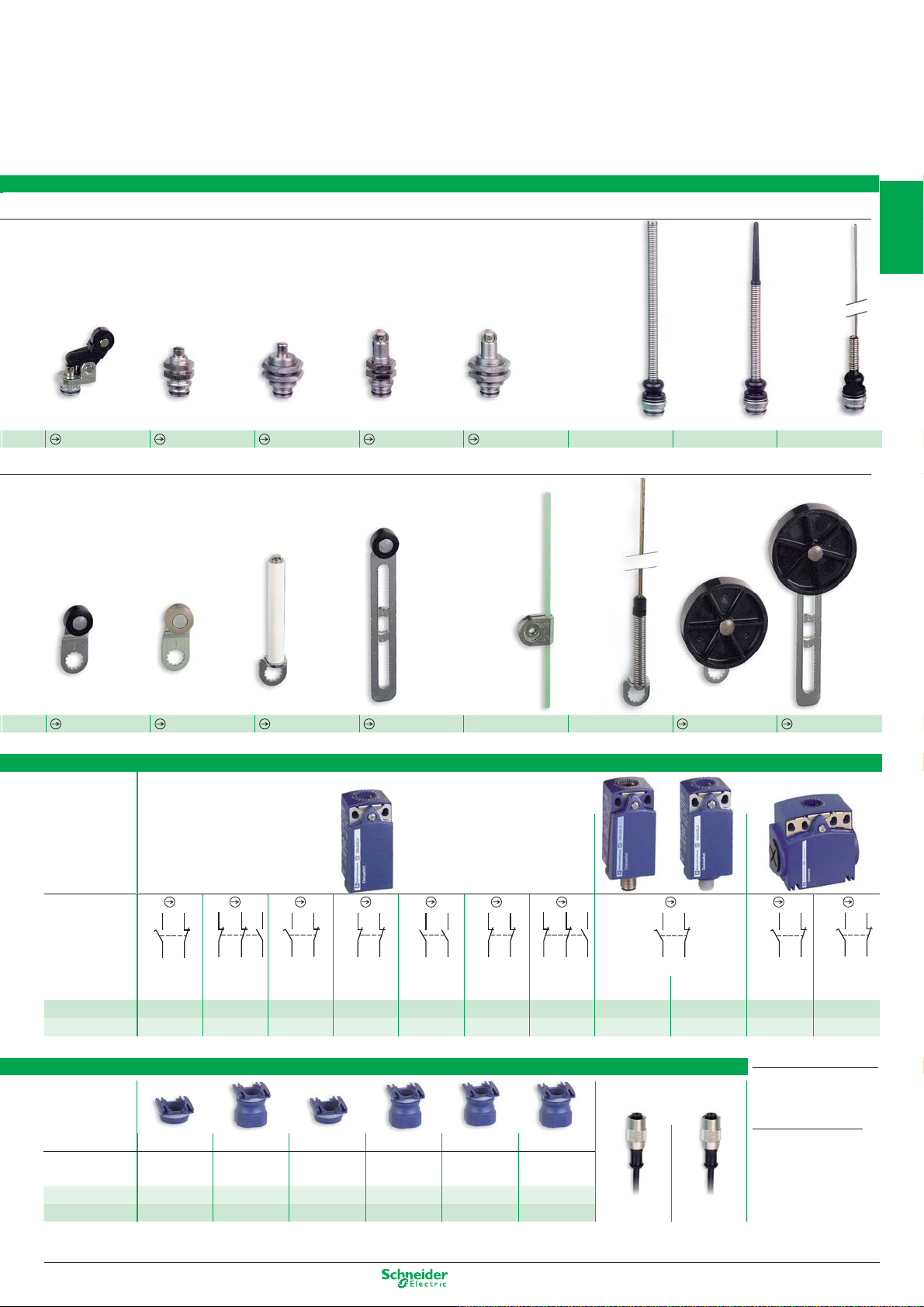
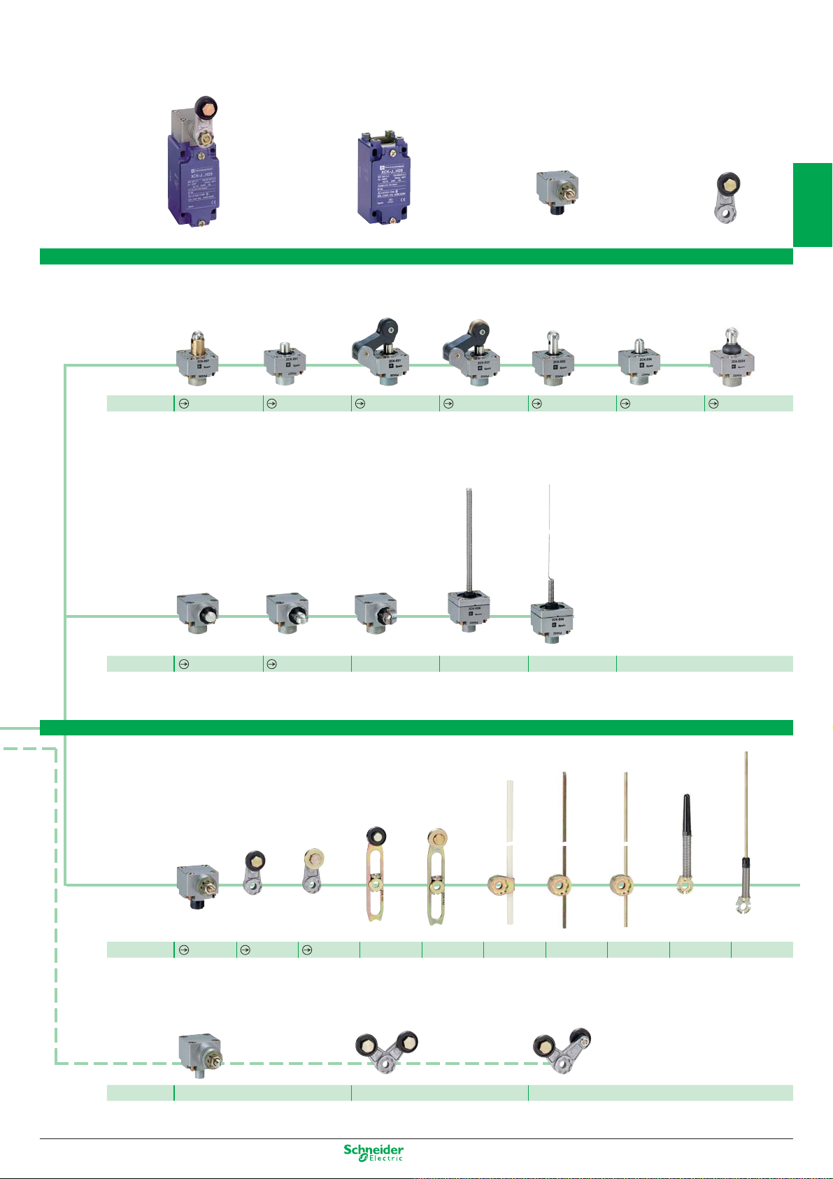
OsiSense XC
Heads - common to miniature and compact bodies
Metal plunger and multi-directional heads
1
2
Description
Limit switches
Customised assembly of miniature and compact
Metal
end plunger
Metal end plunger
with protective
elastomer boot
Steel
roller plunger
Retractable steel
roller lever plunger
Thermoplastic
roller lever plunger,
horizontal actuation
3
4
5
6
Bodies
7
8
Connection of miniature bodies
9
Reference
ZCE10
ZCE11
ZCE02
Metal rotary heads and levers
Description
Reference
Rotary head
without lever,
spring return, for
actuation from
LH or RH side
ZCE01
Thermoplastic
roller lever,
track:
24/31 mm (ZCMD)
29/36 mm (ZCD/P/T)
ZCY15 (2)
(1) Recommended for use with bodies: ZCD... / ZCP... / ZCT...
Steel
roller lever,
track:
24/31 mm (ZCMD)
29/36 mm (ZCD/P/T)
ZCY16 (2)
Miniature
Type of contact
2-pole
NO+NC
Snap action
Reference of metal body ZCMD21 ZCMD39 ZCMD25 ZCMD37 –
Cable L = 1 m ––––
L = 2 m ––––
L = 5 m ––––
(3) For contact 2-pole NC+NO slow break, replace 21 by 25. Example: ZCMD21L1 becomes ZCMD25L1
Specifi c pre-cabled
connection components
3-pole
2NC+1NO
Snap action
2-pole
NC+NO
Slow break
3-pole
2NC+1NO
Slow break
2-pole
NO+NC
Snap action
ZCMD21L1 (3)
ZCMD21L2 (3)
ZCMD21L5 (3)
ZCE24 (2)
Thermoplastic
roller lever,
track:
16/39 mm (ZCMD)
21/44 mm (ZCD/P/T)
ZCY25 (2)
Recommended for use with bodies: ZCMD...
(2)
2-pole
NC+NO
Snap action
Connector 5 pin
ZCMD21C12 ZCMD21M12
––
––
––
Option: pre-wired M12
connector, L = 2 m
ZCE21
Steel
roller lever,
track:
16/39 mm (ZCMD)
21/44 mm (ZCD/P/T)
ZCY25 (2)
1-pole
1C/O
Snap action
Connector 4 pin
BU
BN
RD-WH RD
BK-WH BK
4-pole
2NC+2NO
Snap action
–
ZCMD41L1
ZCMD41L2
ZCMD41L5
5-pin 4-pin
VT
GN-YE
VT-WH
10
for
ZCMD21
for
ZCMD39
for
ZCMD25
for
ZCMD37
L = 1 m ZCMC21L1 ZCMC39L1 ZCMC25L1 ZCMC37L1
L = 2 m ZCMC21L2 ZCMC39L2 ZCMC25L2 ZCMC37L2
L = 5 m ZCMC21L5 ZCMC39L5 ZCMC25L5 ZCMC37L5
XZCP1164L2 XZCP1141L2
Positive opening operation.
1/4
Other versions: please consult our Customer Care Centre.
Page 11
13
14
22
21
32 31
22
21
1314
13
14
22
21
13
14
22
21
13
14
22
21
13
14
22
21
32 31
22
21
1314
switches
Thermoplastic
roller lever plunger,
vertical actuation
ZCE27
Thermoplastic
roller lever,
track:
20/36 mm (ZCMD)
24/40 mm (ZCD/P/T)
M12 head
metal
end plunger
ZCEF0(2)
Steel
roller lever,
track:
20/36 mm (ZCMD)
24/40 mm (ZCD/P/T)
M18 head
metal
end plunger
ZCEH0(1)
Ceramic
roller lever
M12 head
steel
roller plunger
ZCEF2(2)
Variable length
thermoplastic
roller lever
M18 head
steel
roller plunger
ZCEH2(1)
Round,
glass fi bre
rod lever
Ø 3 mm
L = 125 mm
Spring rod Spring rod with
ZCE08 ZCE07 ZCE06
Metal
spring-rod
lever
plastic end
Thermoplastic
roller lever
Ø 50 mm
“Cat’s whisker”
Adjustable thermoplastic roller lever
Ø 50 mm
1
2
3
4
5
ZCY18(1)
ZCY19(1)
Compact
Type of contact
2-pole NC+NO
Snap action
Ref. metal body
Ref. plastic body
ZCD21 ZCD39 ZCD25 ZCD27 ZCD28 ZCD29 ZCD37 ZCD21M12 – – –
ZCP21 ZCP39 ZCP25 ZCP27 ZCP28 ZCP29 ZCP37 – ZCP21M12
Connection of compact bodies
Interchangeable
outlet for cable
gland
Description
Metal
Plastic
For ISO M16 For ISO M20 For Pg 11 For Pg 13.5 For 1/2" NPT
cable gland cable gland cable gland cable gland cable gland cable gland
ZCDEP16 ZCDEP20 ZCDEG11 ZCDEG13 ZCDEN12 ZCDEF12
ZCPEP16 ZCPEP20 ZCPEG11 ZCPEG13 ZCPEN12 ZCPEF12
3-pole
2NC+1NO
Snap action
ZCY22
2-pole NC+NO
Slow break
ZCY45
11
22 21
12
2-pole NC+NC
Slow break
1314
2-pole
NO+NO
Slow break
ZCY55 ZCY91
11
2324
22 21
12
3-pole
NC+NC
2-pole
Snap action
NC+1NO
2
Slow break
For PF 1/2 (G12)
ZCY39
2-pole NC+NO - Snap action
Connector
5-pin
Option: pre-wired M12 connector,
L = 2 m
5-pin 4-pin
XZCP1164L2 XZCP1141L2
Connector
4-pin
ZCY49
2-pole
NC+NO
Snap action
ZCT21P16
(1)
ZCT Pg 11 cable gland versions:
replace the suffi x P16 by G11
Example:
ZCT21P16 becomes ZCT21G11
ZCT 1/2" NPT versions:
replace the suffi x P16 by
N12 (adaptor).
Example:
ZCT21P16 becomes ZCT21N12
1 Cable entry 1/2" NPT
1 Cable entry Pg11
2-pole
Slow break
(1)
ZCT25P16
NC+NO
(1)
.
6
7
8
9
10
Other versions: please consult our Customer Care Centre.
1/5
Page 12
22 21
13
14
22 21
13
14
32 31
22
21
1314
32 31
22
21
1314
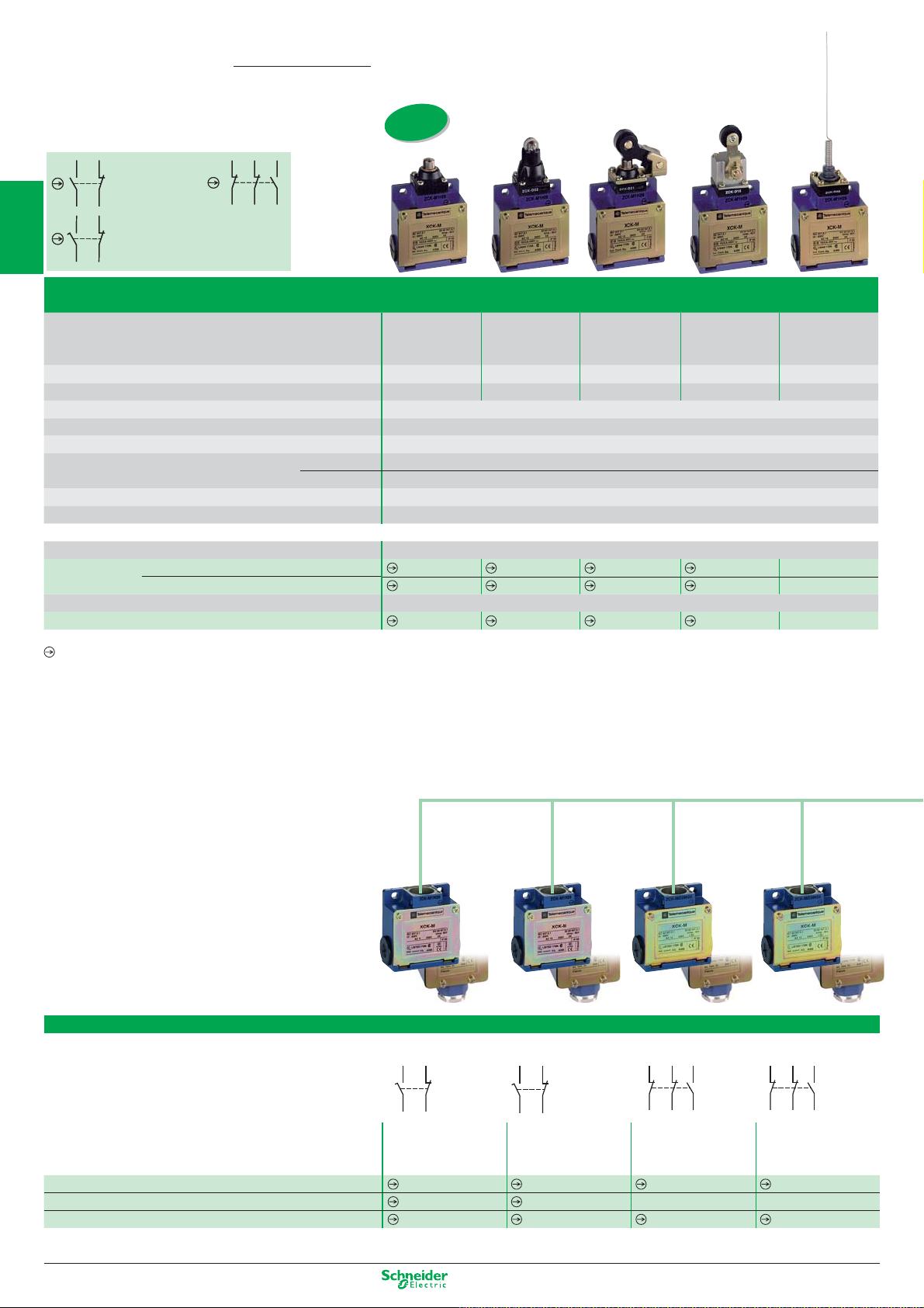
OsiSense XC
XCKM
2-pole contact
21
21
13
13
NC+NO
snap action
22
22
14
14
1314
1314
21
1
21
2-pole contact
NC+NO
slow break
22
22
Type XCKM metal, 3 cable entries, XCKL metal, 1 cable entry
313221
313221
22
22
3-pole contact
2NC+1NO
snap action
13
13
14
14
Limit switches
Classic - XCKM, XCKL, complete switches
ISO entry
to EN 50262)
(
Type of operator Metal
2
Mechanical durability (millions of operating cycles) 20 20 20 15 10
Actuation speed (in m/s) 0.5 0.5 1.5 1.5 0.5
Product certifi cation CE - UL - CSA - CCC - GOST - C-TICK - BV
Degree of protection conforming to IEC 60529 IP 665
3
Rated operational characteristics AC-15; A300 (Ue = 240 V, Ie = 3 A) / DC-13; Q300 (Ue = 250 V, Ie = 0.27 A)
Cable entry (1) XCKM 3 tapped entries for ISO M20 x 1.5 cable gland (2 entries fi tted with blanking plugs)
XCKL 1 cable entry with cable gland
Fixing centres (mm) 41
Body dimensions (mm) W x D x H
4
Complete switch XCKM
2-pole NC+NO snap action
2-pole NC+NO, break before make, slow break
Complete switch XCKL
2-pole NC+NO snap action
(1) For Pg 13.5 cable entries delete the reference suffi x H29. Example: XCKM110H29 becomes XCKM110.
5
Positive opening operation.
XCKM / XCKL 64 x 30 x 64 / 52 x 30 x 72
end plunger
XCKM110H29 XCKM102H29 XCKM121H29 XCKM115H29
XCKM510H29 XCKM502H29 XCKM521H29 XCKM515H29
XCKL110
Steel
roller plunger
XCKL102
Roller lever plunger,
horizontal actuation
in 1 direction
XCKL121
Thermoplastic
roller lever
XCKL115
Classic - XCKM, XCKL,
6
Customised assembly - Body/contact sub-assemblies
“Cat’s whisker”
XCKM106H29
–
XCKL106
7
8
Type XCKM metal, 3 cable entries
Type of contact
9
10
Reference of body with contact block
XCKL reference of body with contact block (2)
Reference of contact block only
(2) For cable entry 1/2" NPT, add H7. Example: XCKL1 becomes XCKL1H7
1/6
2-pole
NC+NO
snap action
ZCKM1H29
ZCKL1
XE2SP2151
2-pole
NC+NO
slow break
ZCKM5H29
ZCKL5
XE2NP2151
3-pole
2NC+1NO
snap action
ZCKMD39H29
––
XE3SP2141
Other versions: please consult our Customer Care Centre.
3-pole
2NC+1NO
slow break
ZCKMD37H29
XE3NP2141
Page 13
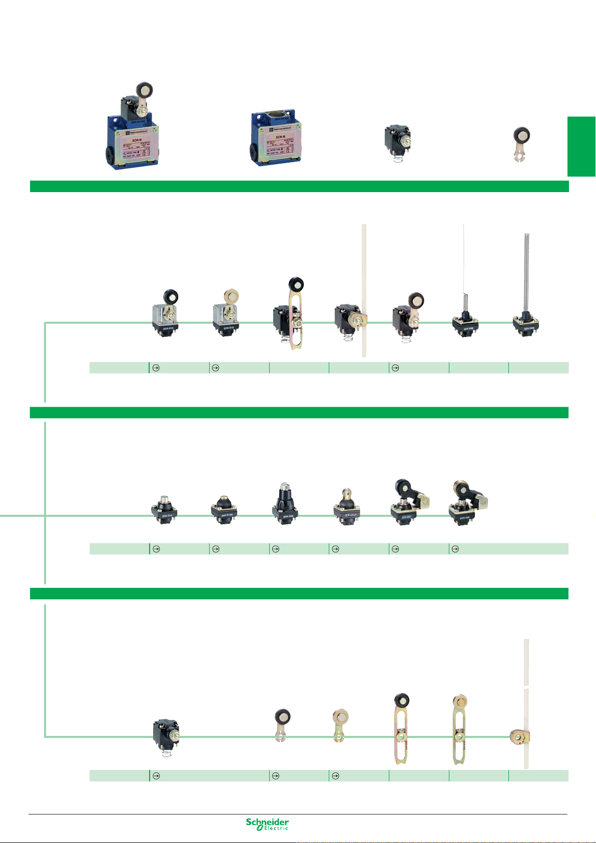
Operating heads,
complete or for customer assembly
1
Complete switch
Rotary or multi-directional heads
Reference
Plunger heads
metal head with
thermoplastic
roller lever
ZCKD15
with metal
end plunger
=
metal head with
steel roller lever
with metal end
plunger and
protective boot
Body/contact assembly
ZCKD16
+
with variable length
thermoplastic
roller lever (2)
ZCKD41 ZCKD59
with steel
roller plunger
with Ø 6 mm
thermoplastic rod
L = 200 mm (3)
with steel roller
plunger and
protective boot
Head
with thermoplastic
roller lever (3)
for actuation from
left AND right
or
left OR right
+
with “Cat’s
whisker”
Lever
with spring rod
2
3
4
ZCKD31
with thermoplastic
roller lever plunger,
horizontal actuation
in 1 direction
ZCKD06 ZCKD08
with steel
roller lever plunger,
horizontal actuation
in 1 direction
5
Reference
ZCKD10
ZCKD109
ZCKD02
Rotary heads and separate levers
spring return,
for actuation from
left AND right
or
left OR right
Reference
(2) Adjustable throughout 360° in 5° steps, or in 90° steps by reversing the notched washer.
(3) Adjustable throughout 360° in 5° steps, or in 45° steps by reversing the lever mounting.
ZCKD05
lever with
thermoplastic
roller (2)
ZCKY31
ZCKD029
lever with
steel roller (2)
ZCKY33
ZCKD21
variable length
lever with
thermoplastic
roller
(2)
ZCKY41 ZCKY43 ZCKY59
ZCKD23
variable length
lever with
steel roller (2)
rod, Ø 6 mm
thermoplastic
L = 200 mm (3)
6
7
8
9
10
Other versions: please consult our Customer Care Centre.
1/7
Page 14
OsiSense XC
XCKJ
2-pole contact
21
21
13
13
NC+NO
snap action
14
14
22
22
1314
1314
21
1
21
2-pole contact
NC+NO
22
22
slow break
Type XCKJ metal, fixed body, conforming to standard EN 50041
313221
313221
22
22
3-pole contact
2NC+1NO
snap action
13
13
14
14
Limit switches
Industrial - XCKJ, complete switches
ISO entry
to EN 50262)
(
Type of operator Metal
2
Mechanical durability (millions of operating cycles) 30 25 30 30 30 30
Actuation speed (in m/s)
Product certification CE - UL - CSA - CCC - GOST - C-TICK - BV
Degree of protection conforming to IEC 60529 IP 667
Rated operational characteristics AC-15; A300 (Ue = 240 V, Ie = 3 A) / DC-13; Q300 (Ue = 250 V, Ie = 0.27 A)
3
Cable entry (1) 1 tapped entry for ISO M20 x 1.5 cable gland
Fixing centres (mm) 30 x 60
Body dimensions (mm) W x D x H 40 x 44 x 77
Complete switch
4
(1) For Pg 13.5 cable entry delete the reference suffix H29. Example: XCKJ161
Positive opening operation.
M20
2-pole NC+NO snap action
2-pole NC+NO break before make, slow break
1/2" NPT
2-pole NC+NO snap action
M12 5P
2-pole NC+NO snap action
end plunger
0.5 1 1.5 1,5 1.5 1.5
XCKJ161H29 XCKJ167H29 XCKJ10511H29
XCKJ561H29 XCKJ567H29 XCKJ50511H29
XCKJ161H7 XCKJ167H7
XCKJ161D XCKJ167D XCKJ10511D
H29 becomes XCKJ161.
Steel
roller plunger
Thermoplastic
roller lever
XCKJ10511H7
Steel
roller lever
XCKJ10513H29
XCKJ50513H29
XCKJ10513H7
XCKJ10513D
5
Industrial - XCKJ,
6
Customised assembly - Body/contact sub-assemblies
Variable length
thermoplastic
roller lever
XCKJ10541H29 XCKJ10559H29
XCKJ50541H29 XCKJ50559H29
XCKJ10541H7 XCKJ10559H7
XCKJ10541D XCKJ10559D
Polyamide Ø 6
mm rod lever
L = 200 mm
7
8
9
10
Type XCKJ metal, 1 cable entry
Type of contact
Cable entry (1) 1 tapped entry for ISO M20 x 1.5 cable gland
Reference of body with contact block
Reference of contact block only
1/8
M20
Pg13
1/2" NPT
M12 (5 pin)
13
22 21
14
2-pole
NC+NO
snap action
ZCKJ1H29
ZCKJ1
ZCKJ1H7
ZCKJ1D
XE2SP2151
13
22 21
14
2-pole
NC+NO
slow break
ZCKJ5H29
ZCKJ5
ZCKJ5H7
ZCKJ5D
XE2NP2151
1314
11
21
23
13
22
24
14
12
2 C/O
snap action
Simultaneous
ZCKJ2H29
ZCKJ2 – –
ZCKJ2H7 – –
–––
–
Other versions: please consult our Customer Care Centre.
21
22
32 31
3-pole
2NC+1NO
snap action
ZCKJD39H29
XE3SP2141
21
32 31
22
3-pole
2NC+1NO
slow break
ZCKJD37H29
XE3NP2141
1314
Page 15
Operating heads,
complete or for customer assembly
Complete switch = Body/contact assembly + Head + Lever
Plunger or multi-directional heads
with reinforced
steel roller
end plunger
with metal
end plunger
with thermoplastic
roller lever plunger,
1 direct. of actuation
with steel
roller lever plunger,
1 direct. of actuation
with steel roller
end plunger
with steel
ball bearing
end plunger
End steel roller
plunger with
protective boot
1
2
Référence
Reference
ZCKE67
with metal
side plunger
ZCKE63
Separate rotary heads and levers
spring return
for actuation
from
left AND right
or
left OR right
ZCKE61
Side steel roller
plunger,
horizontal
ZCKE64
lever with
thermoplastic
roller (2)
lever with
steel roller (2)
ZCKE21
Side steel roller
plunger,
vertical
ZCKE65 ZCKE08 ZCKE06
variable length
lever with
thermoplastic
roller (2)
ZCKE23
with spring rod with “Cat’s whisker”
variable length
lever with
steel roller (2)
rod, Ø 6 mm
thermoplastic
L = 200 mm (2)
ZCKE62
square rod lever,
steel, U 3 mm
L = 125 mm (2)
ZCKE66
round rod lever,
steel, Ø 3 mm
L = 125 mm (2)
spring lever
with
thermoplastic
end (3)
ZCKE629
spring-metal
rod lever
(3)
3
4
5
6
7
Reference
Reference ZCKE09 ZCKY71 ZCKY61
(2) Adjustable throughout 360° in 5° steps, or in 45° steps by reversing the lever mounting.
(3) Adjustable throughout 360° in 5° steps, or in 90° steps by reversing the notched washer.
ZCKE05 ZCKY11 ZCKY13
stay put
for actuation from
left AND right
ZCKY41 ZCKY43 ZCKY59 ZCKY51 ZCKY53 ZCKY81 ZCKY91
forked arm lever
with thermoplastic
rollers, 1 track (2)
8
9
forked arm lever
with thermoplastic
rollers, 2 track (2)
10
Other versions: please consult our Customer Care Centre.
1/9
Page 16
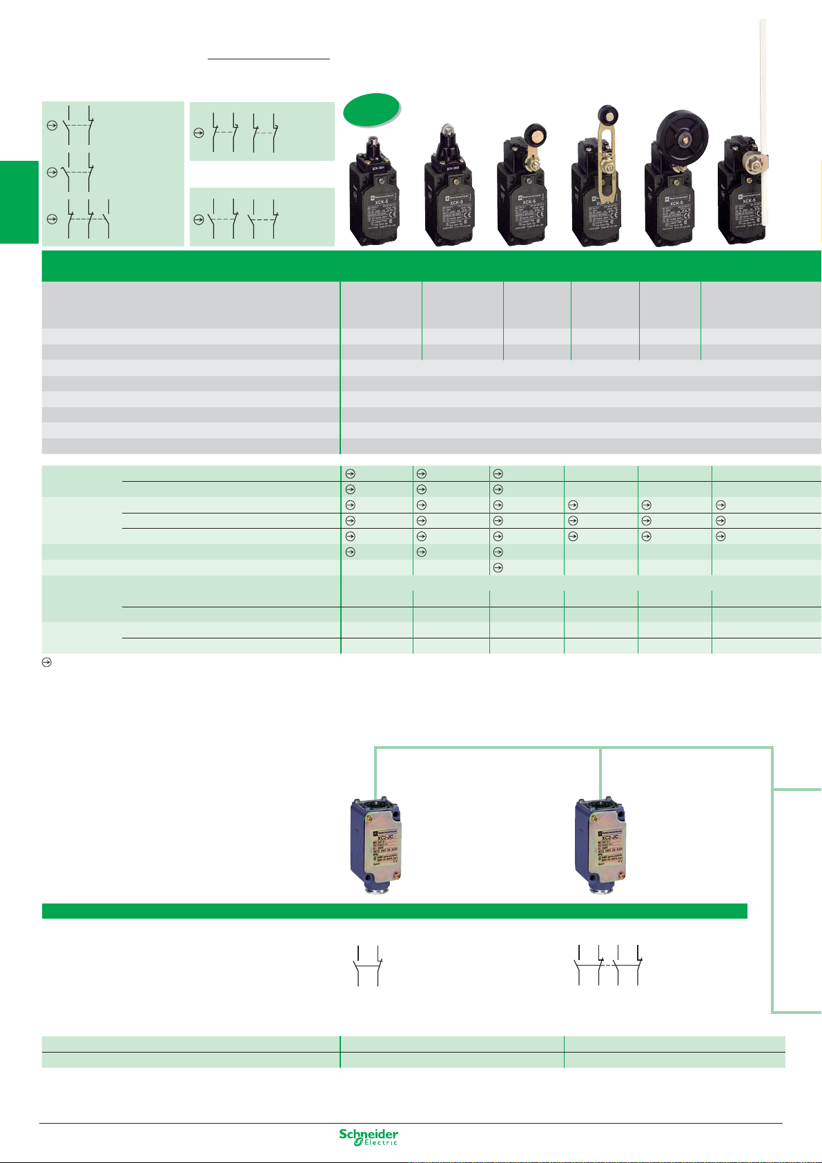
OsiSense XC
XCKS
2-pole contact
21
1
13
14
1314
313221
Type XCKS plastic, double insulated, conforming to standard EN 50041
22
21
22
22
NC+NO
snap action
2-pole contact
NC+NO
slow break
3-pole
13
2NC+1NO
snap action
14
XCKMR
11
12
XCR
13
14
Limit switches
Classic - XCKS, complete switches
21
22
21
22
2 x 2-pole
21
1112
contacts
NC+NC
staggered,
22
slow break
2 x 2-pole
21
1314
contacts,
snap action
22
ISO entry
to EN 50262)
(
2
3
4
5
6
Type of operator Metal
end plunger
Mechanical durability (millions of operating cycles)
Actuation speed (in m/s)
Product certification CE - UL - CSA - CCC - GOST - C-TICK
Degree of protection conforming to IEC 60529 IP 653
Rated operational characteristics AC-15; A300 (Ue = 240 V, Ie = 3 A) / DC-13; Q300 (Ue = 250 V, Ie = 0.27 A)
Cable entry (1) 1 tapped entry for ISO M20 x 1.5 cable gland
Fixing centres (mm) 30 x 60
Body dimensions (mm) W x D x H 40 x 36 x 72.5
Complete switch 2-pole NC+NO snap action
2-pole NC+NO break before make, slow break
Body 2-pole NC+NO snap action
2-pole NC+NO break before make, slow break
3-pole 2NC+1NO snap action
Associated head (including operator)
Operating lever for rotary head
Complete switch
Complete switch 2 C/O staggered snap action contacts –– – – – –
Positive opening operation.
Snap-action 2-pole 2X (1 NC + 1 NO) contact
Both contacts act in each direction of actuation –– – – – –
1 contact operates in each direction –
2 (NC + NO) staggered, slow break contacts
(1)
25 15 20 20 20 20
0.5 0.5 1.5 1.5 1 1
XCKS101H29 XCKS102H29 XCKS131H29
XCKS501H29 XCKS502H29 XCKS531H29
ZCKS1H29 ZCKS1H29 ZCKS1H29 ZCKS1H29 ZCKS1H29 ZCKS1H29
ZCKS5H29 ZCKS5H29 ZCKS5H29 ZCKS5H29 ZCKS5H29 ZCKS5H29
ZCKSD39H29 ZCKSD39H29 ZCKSD39H29 ZCKSD39H29 ZCKSD39H29 ZCKSD39H29
ZCKD01
––
–– – – – –
For Pg 13.5 cable entry delete the reference suffix H29. Example: XCKJ161H29 becomes XCKJ161.
Steel
roller plunger
ZCKD02
–––––
Thermoplastic
roller lever
ZCKD31
ZCKY31
Variable length
thermoplastic
roller lever
XCKS141H29 XCKS139H29 XCKS159H29
XCKS541H29 XCKS539H29 XCKS559H29
ZCKD41 ZCKD39 ZCKD59
ZCKY41 ZCKY39 ZCKY59
Rubber
roller lever
Ø 50 mm
Polyamide
rod lever
L = 200 mm
Ø 6 mm
7
8
9
10
For severe applications - XC2J,
Customised assembly - Body/contact sub-assemblies
Type XC2J metal, fixed body, 1 cable entry incorporating cable gland
Type of contact
13
12 11
14
Single-pole
Reference of body with contact block
Reference of contact block only
1 C/O contact
snap action
ZC2JC1
XCKZ01
23
13
22 21
12 11
24
14
Double-pole
2 C/O simultaneous contacts
snap
action
ZC2JC2
XESP1021
1/10
Other versions: please consult our Customer Care Centre.
Page 17
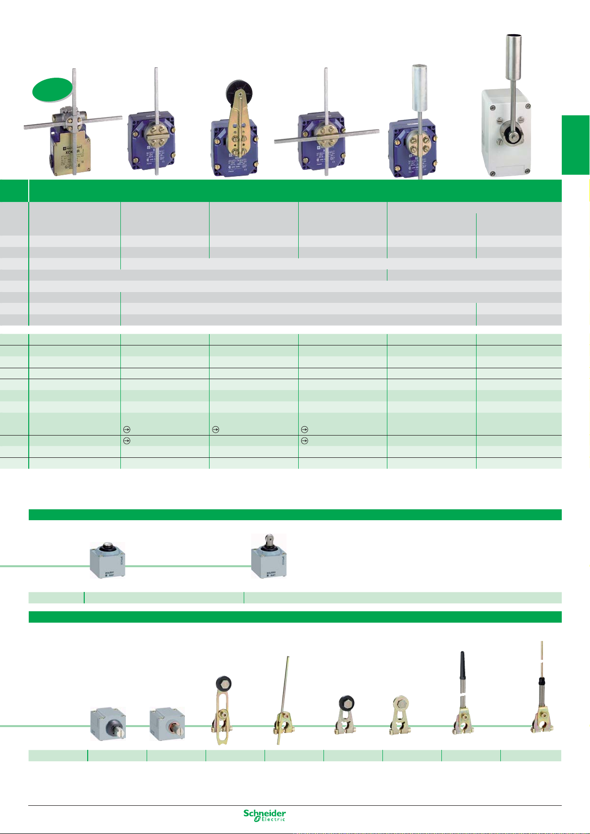
Severe duty for hoisting and materials handling applications
XCKMR and XCR, complete switches
ISO entry
to EN 50262)
(
Types XCKMR and XCR “Application - hoisting, materials handling, conveying”
1
Square rod levers Square rod lever Large roller rod lever Square rod levers Conveyor belt shift monitoring switches
6 mm, “crossed” 6 mm Ø 50 mm 6 mm, “crossed” or “T”
2 10 10 10 0.3 0.3
1.5 1.5 1.5 1.5 1.5 1.5
CE - UL - CSA - GOST CE - CSA - CCC - GOST
IP 545 IP 665
AC-15; A300 (Ue = 240 V, Ie = 3 A) / DC-13; Q300 (Ue = 250 V, Ie = 0.27 A)
3 x ISO M20 x 1.5 entries 1 tapped entry for n° 13 cable gland (for ISO M20 x 1.5, adaptor DE9RA1620 must be ordered separately)
61.5 85 x 75 105 x 70
118 x 59 x 77 85 x 75 x 95 85 x 87 x 146
– –––––
– –––––
– –––––
– –––––
– –––––
– –––––
– –––––
–
–
– XCRT115 XCRT315 (4)
XCKMR54D1H29 (2) –––––
(2) Steel rods, L = 200 mm (3) Steel “T” rods, L = 200 mm, W = 300 mm. (4) Polyester enclosure
XCRA11(2)
XCRB11(2)
XCRA15
–
XCRE18(2)
XCRF17(3)
Galvanised steel
operating lever
––
––
Stainless steel
operating lever
2
3
4
5
6
Operating heads, complete or for customer assembly
Plunger heads
with metal end plunger with steel roller end plunger
Reference ZC2JE61 ZC2JE62
Rotary heads and separate levers
spring return
for actuation from
left
AND right
Reference ZC2JE01 ZC2JE05 ZC2JY31 ZC2JY51 ZC2JY11 ZC2JY13 ZC2JY81 ZC2JY91
ry head(1) Adjustable throughout 360°. s and separate levers
spring return
for actuation from
left
OR right
variable length lever
with thermoplastic
roller (1)
rigid rod
3 mm, steel
L = 125 mm (1)
lever with
thermoplastic roller
(1)
lever with
steel roller (1)
spring lever
(1)
7
8
spring-rod lever
9
10
Other versions: please consult our Customer Care Centre.
1/11
Page 18
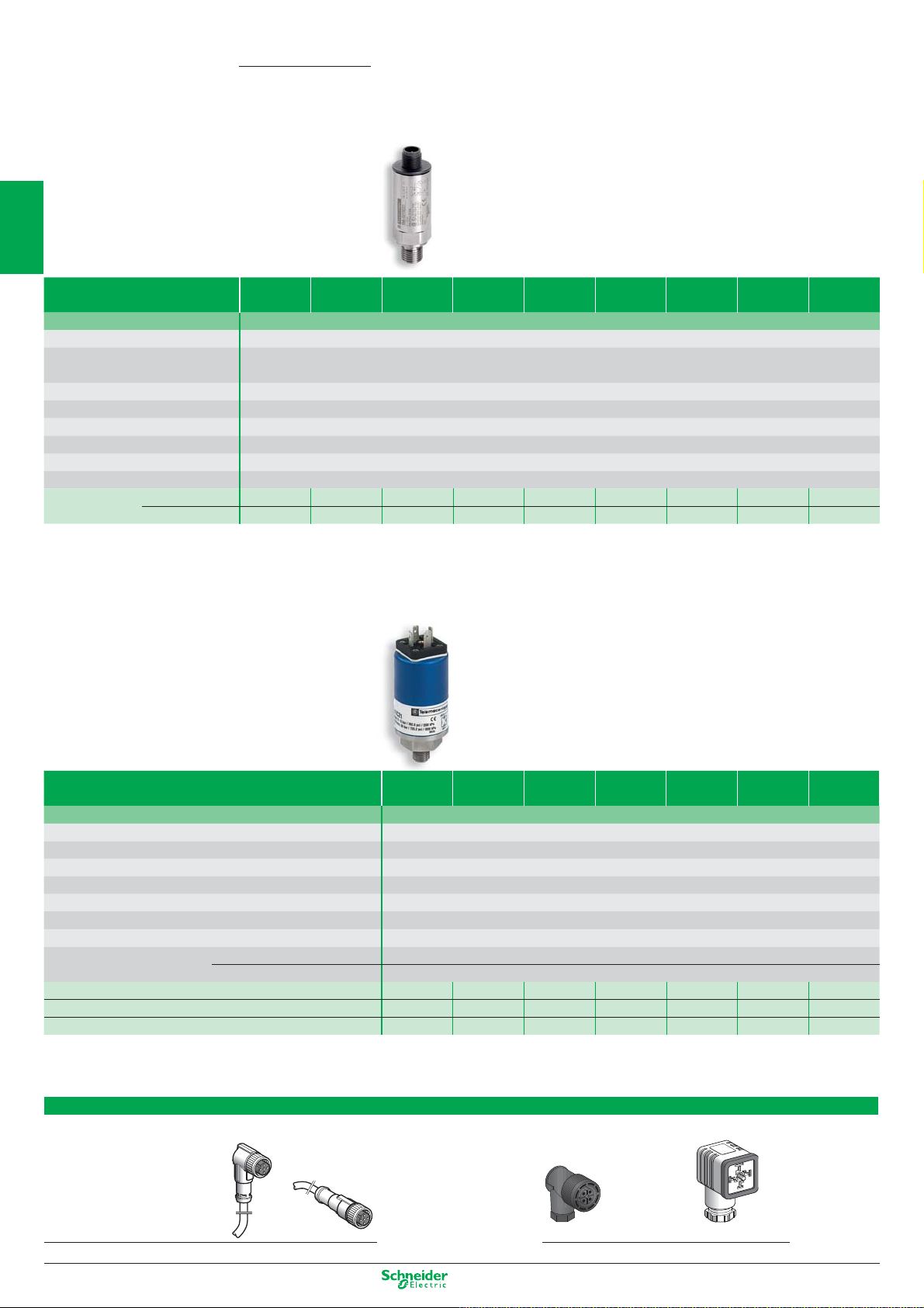
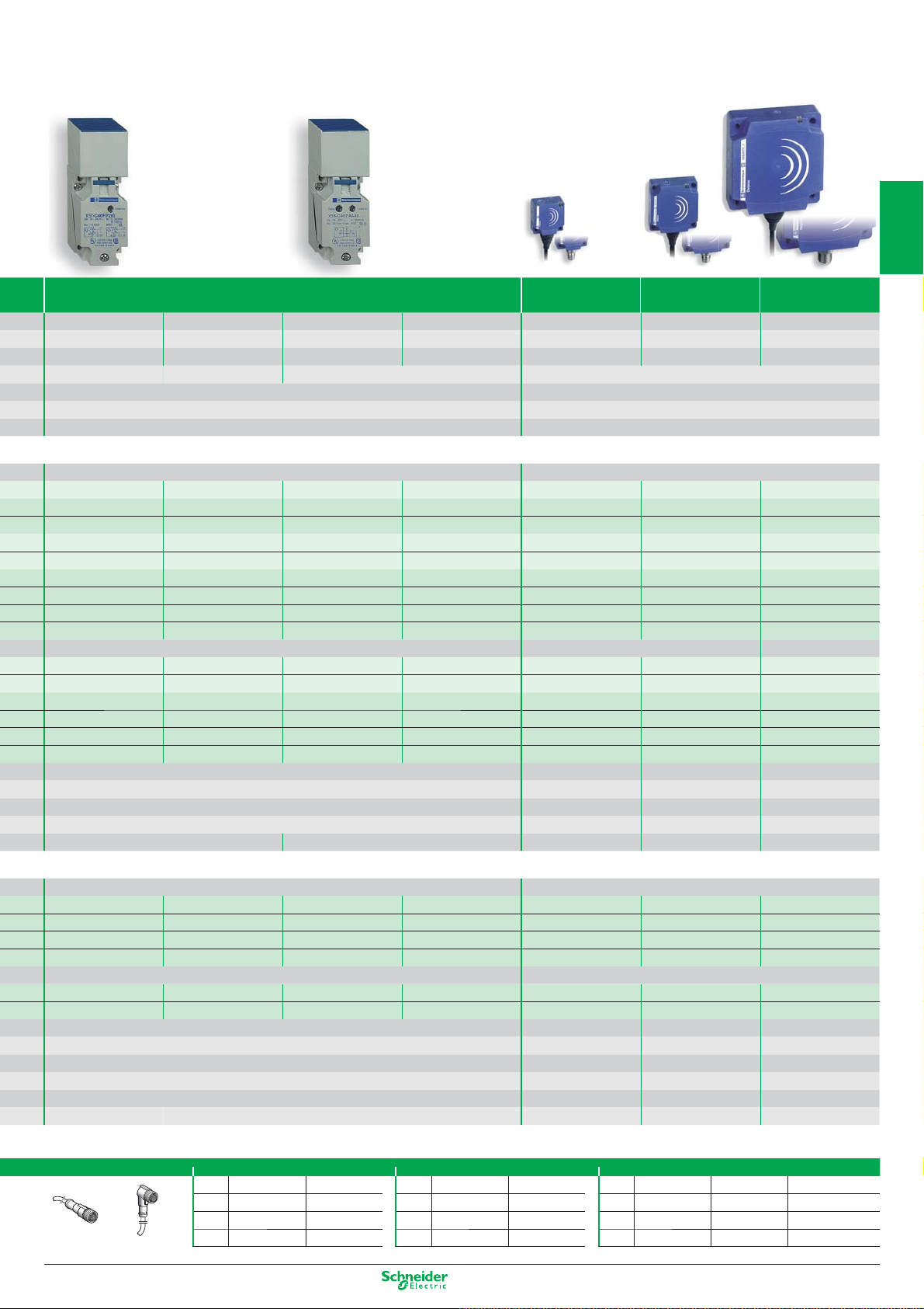
OsiSense XM
1
Sensors for pressure control
Electronic sensors XMLG
Electrical connection by M12 connector
Pressure range
(bar) (1)
Fluids controlled Hydraulic oils, air, fresh water, sea water, corrosive fluids from -15…+125°C
2
Ambient air temperature - 15…+ 85°C
Degree of protection
(conforming to IEC 60529)
Product certification CE - UL - CSA - GOST
Voltage limits 12…24 V DC, 8…33 V DC for 4…20 mA, 11.4…33V DC for 0…10 V
Dimensions (mm) Ø x L Ø 22.8 x 70 (not including connector)
3
Fluid connection (2) G 1/4" A (male)
Electrical connection (3) M12 connector
Type of output (4) 4…20 mA, 2-wire technique, 0…10V, 3-wire technique
Analogue output 4…20 mA
0…10 V
Available in bulk packs for selling in lots, please consult us.
4
The XMLG range also includes pressure switches, please consult us.
-1…0 0…1 0…6 0…10 0…16 0…25 0…100 0…250 0…400
IP 66 and IP 67
XMLGM01D21
XMLGM01D71
XMLG001D21 XMLG006D21 XMLG010D21 XMLG016D21 XMLG025D21 XMLG100D21 XMLG250D21 XMLG400D21
XMLG001D71 XMLG006D71 XMLG010D71 XMLG016D71 XMLG025D71 XMLG100D71 XMLG250D71 XMLG400D71
Electronic sensors XMLE
Electrical connection by DIN 43650 connector
5
6
Setting range
(bar) (1)
Fluids controlled Hydraulic oils, air, fresh water, sea water, corrosive fluids from -15…+80°C
Ambient air temperature - 15…+ 80°C
Degree of protection (conforming to IEC 60529) IP 65
7
Product certification CE - UL - CSA - GOST
Voltage limits 24 V DC, 11…33 V DC
Dimensions (mm) Ø x L Ø 40 x 90 (not including connector)
Fluid connection (2) G 1/4" A (male)
Electrical connection (3) DIN 43650 connector
Type of output (4)
8
Analogue output 4…20 mA
NPN output
PNP output
(1) Other sizes, please consult us. (3) Other types of connection, please consult us.
(2) Other fluid connections, please consult us. (4) Other types of output; 0…5 V, 0…10 V, etc., please consult us.
Transmitter 4…20 mA, 2-wire technique
Pressure switch PNP or NPN, normally closed (NC)
-1…0 0…1 0…10 0…25 0…100 0…250 0…600
XMLEM01U1C21 XMLE001U1C21 XMLE010U1C21 XMLE025U1C21 XMLE100U1C21 XMLE250U1C21 XMLE600U1C21
XMLEM01U1C31 XMLE001U1C31 XMLE010U1C31 XMLE025U1C31 XMLE100U1C31 XMLE250U1C31 XMLE600U1C31
XMLEM01U1C41 XMLE001U1C41 XMLE010U1C14 XMLE025U1C41 XMLE100U1C41 XMLE250U1C41 XMLE600U1C41
9
Suitable female plug-in connectors
Pre-wired connectors, L = 5 m (without LED) Other connectors
10
elbowed straight Screw terminal DIN 43650A
M12 XZCP1241L5 XZCP1141L5 XZCC12FCM40B XZCC43FCP40B
1/12
Other versions: please consult our Customer Care Centre.
Page 19
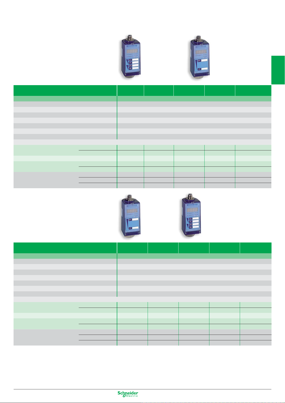
Electronic sensors XMLF
1
Setting range
(bar)
Fluids controlled Hydraulic oils, air, fresh water, sea water, corrosive fluids from -15…+80°C
Ambient air temperature - 25…+ 80°C
Degree of protection (conforming to IEC 60529) IP 67
Product certification CE - UL - CSA - VIT-SEPRO - GOST
Voltage limits (V) 24 V DC (17…33 V DC)
Dimensions (mm) H x W x D 113 x 46 x 58
Fluid connection G 1/4" (female) (1)
Electrical connection M12 connector (2)
Configurable with digital display, connection by M12 connector (3)
Universal sensors, 4...20 mA
solid-state output, 200 mA (4) 0...10 V
Dual stage pressure switches, solid-state output, 200 mA
Analogue sensors 4...20 mA
Possible differential (bar) Min. at low setting
(pressure switches) Min. at high setting
of lower limit (PB):
of upper limit (PH):
vacuum switches
pressure switches
0...10 V
Max. at high setting
-0.08…-1 0.08...1 0.2…2.5 0.8…10
XMLFM01D2025 XMLF001D2025 XMLF002D2025 XMLF010D2025 XMLF040D2025
XMLFM01D2125 XMLF001D2125 XMLF002D2125 XMLF010D2125 XMLF040D2125
XMLFM01D2035 XMLF001D2035 XMLF002D2035 XMLF010D2035 XMLF040D2035
XMLFM01D2015 XMLF001D2015 XMLF002D2015 XMLF010D2015 XMLF040D2015
XMLFM01D2115 XMLF001D2115 XMLF002D2115 XMLF010D2115 XMLF040D2115
0.03 0.03 0.08 0.3 1.2
0.03 0.03 0.08 0.3 1.2
0.95 0.95 2.38 9.5 38
3.2...40
2
3
4
5
Setting range
(bar)
Fluids controlled Hydraulic oils, air, fresh water, sea water, corrosive fluids from -15…+80°C
Ambient air temperature - 25…+ 80°C
Degree of protection (conforming to IEC 60529) IP 67
Product certification CE - UL - CSA - VIT-SEPRO - GOST
Voltage limits (V) 24 V DC (17…33 V DC)
Dimensions (mm) H x W x D 113 x 46 x 58
Fluid connection G 1/4" (female) (1)
Electrical connection M12 connector (2)
Configurable with digital display, connection by M12 connector (3)
Universal sensors, 4...20 mA
solid-state output, 200 mA (4) 0...10 V
Dual stage pressure switches, solid-state output, 200 mA
Analogue sensors 4...20 mA
Possible differential (bar) Min. at low setting
(pressure switches) Min. at high setting
(1) Available with other fluid connections: 1/4" NPT female and SAE 7/16-20 UNF.
(2) For M12 connection accessories, see previous page.
(3) AC 120 V version with 2.5 A relay output and SAE 7/8-16 UN connector also available.
(4) Programmable NPN or PNP and NO or NC.
of upper limit (PH): pressure switches
0...10 V
Max. at high setting
8…100 12.8...160 20...250 32...400
XMLF100D2025 XMLF160D2025 XMLF250D2025 XMLF400D2025 XMLF600D2025
XMLF100D2125 XMLF160D2125 XMLF250D2125 XMLF400D2125 XMLF600D2125
XMLF100D2035 XMLF160D2035 XMLF250D2035 XMLF400D2035 XMLF600D2035
XMLF100D2015 XMLF160D2015 XMLF250D2015 XMLF400D2015 XMLF600D2015
XMLF100D2115 XMLF160D2115 XMLF250D2115 XMLF400D2115 XMLF600D2115
3 4.8 7.5 12 18
3 4.8 7.5 12 18
95 152 237.5 380 570
48...600
6
7
8
9
10
Other versions: please consult our Customer Care Centre.
1/13
Page 20
OsiSense XM
1 C/O
11
13
1
single-pole
contact,
snap action
12
14
ISO entry
to EN 50262)
(
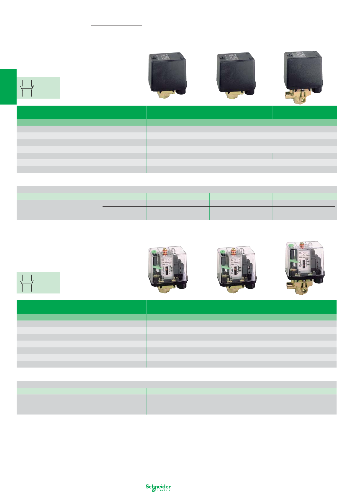
Sensors for pressure control
Electromechanical pressure and vacuum switches
XMLA and B
Size (bar) -1 5 1 2.5
Environmental characteristics Ambient air temperature (°C): - 25…+ 70 Degree of protection (conforming to IEC 60529): IP 66
2
Rated operational characteristics AC-15; B300 (Ue = 240 V, Ie = 1.5 A - Ue = 120 V, Ie = 3 A) / DC-13; R300 (Ue = 250 V, Ie = 0.1 A)
Product certification CE - UL - CSA - CCC - BV - LROS - RINA - GL - DNV - VIT-SEPRO - GOST
Fluid connection G 1/4" (female) (other connections possible, please consult us)
Electrical connection Screw terminals (1), tapped entry for ISO M20 x 1.5 cable gland -
3
Fluids controlled
Hydraulic oils, fresh water,
sea water, air up to 70°C
Hydraulic oils,
air up to 160°C
For n° 13 (DIN Pg 13.5) cable gland
Type XMLA - fixed differential, single threshold detection
Setting range (bar) of upper limit (PH): pressure switches -0.28…-1 (4) – 0.03…1 0.15…2.5
Dimensions (mm) H x W x D 113 x 35 x 75 113 x 35 x 75 162 x 110 x 110 158 x 55 x 77.5
With setting scale 1 C/O single-pole, snap action contact
Natural differential (bar) at low setting 0.24 (2)
4
subtract from PH to give PB at high setting 0.24 (2)
XMLAM01V2S12 – XMLA001R2S12 XMLA002A2S12
– 0.02 0.13
– 0.04 0.13
Hydraulic oils
sea water, air up to 70°C
, fresh water,
Type XMLB - adjustable differential, regulation between 2 thresholds
Setting range (bar) of upper limit (PH): pressure switches -0.14...-1 (4) -0.5...5 0.05...1 0.3...2.5
With setting scale 1 C/O single-pole, snap action contact XMLBM02V2S12 XMLBM05A2S12 XMLB001R2S12 XMLB002A2S12
Possible differential (bar) Min. at low setting 0.13 (3)
5
subtract from PH to give PB Min. at high setting 0.13 (3)
Max. at high setting 0.8 (3)
XMLC and D
6
XMLC
23
24
23
24
2 C/O single-pole
contacts,
simultaneous
22 21
snap action
2 C/O single-pole
contacts,
snap action
22 21
(1 per stage)
11
13
12
14
XMLD
7
11
13
12
14
Fluids controlled
8
Type XMLC - adjustable differential, regulation between 2 thresholds
Setting range (bar) of upper limit (PH): pressure switches -0.14...-1 (4) -0.55...5 0.05...1 0.3...2.5
Dimensions (mm) H x W x D 113 x 46 x 85 113 x 46 x 85 175 x 110 x 110 158 x 55 x 90
With setting scale 2 C/O single-pole, snap action contacts XMLCM02V2S12 XMLCM05A2S12 XMLC001R2S12 XMLC002B2S12
Possible differential (bar) Min. at low setting 0.13 (4)
subtract from PH to give PB Min. at high setting 0.14 (4)
9
Type XMLD - fixed differential, dual stage, for detection at each threshold
Setting range
(bar)
10
Without setting scale
Natural differential (bar)
subtract from PH 1/2 to give PB 1/2 at high setting 0.1 (2) – 0.07 0.19
2nd stage switching point (PB2) -0.12...-1 (4) – 0.12...1 0.34...2.5
st
stage switching point (PB1) -0.10...-0.98 – 0.04...0.92 0.2...2.36
1
Spread between 2 stages (PB2 – PB1)
2 C/O single-pole, snap action contacts (1 per stage)
ISO entry
to EN 50262)
(
Hydraulic oils, fresh water,
sea water, air up to 70°C
Max. at high setting 0.8 (4)
-0.02...-0.88 – 0.08...0.73 0.14...1.5
XMLDM02V1S12 – XMLD001R1S12 XMLD002B1S12
at low setting 0.1 (2)
0.5 0.04 0.16
0.5 0.06 0.21
6 0.75 1.75
0.45 0.03 0.13
0.45 0.04 0.17
6 0.8 2
– 0.03 0.14
Hydraulic oils,
air up to 160°C
Hydraulic oils
sea water, air up to 160°C
, fresh water,
1/14
Other versions: please consult our Customer Care Centre.
Page 21
4 10 20 35 70 160 300 500
1
conforming to IEC 947-5-1 Appendix A, EN 60 947-5-1
tapped entry, replace the last number of the reference (2) by 1 (example: XMLA010A2S12 becomes XMLA010A2S11)
Hydraulic oils, fresh water,
sea water, air up to 70°C
0.4…4 0.6…10 1…20 1.5…35 5…70 10…160 20…300 30…500
113 x 35 x 75 113 x 35 x 75 113 x 35 x 75 113 x 35 x 75 113 x 35 x 75 113 x 35 x 75 113 x 35 x 75 113 x 35 x 75
XMLA004A2S12 XMLA010A2S12 XMLA020A2S12 XMLA035A2S12 XMLA070D2S12 XMLA160D2S12 XMLA300D2S12 XMLA500D2S12
0.35 0.5 0.4 1.25 3 5.5 16.5 20
0.35 0.5 1 1.25 7.5 18 35 45
0.25...4 0.7...10 1.3...20 3.5...35 7...70 10...160 22...300 30...500
XMLB004A2S12 XMLB010A2S12 XMLB020A2S12 XMLB035A2S12 XMLB070D2S12 XMLB160D2S12 XMLB300D2S12 XMLB500D2S12
0.02 0.57 1 1.7 4.7 9.3 19.4 23
0.25 0.85 1.6 2.55 8.8 20.8 37 52.6
2.4 7.5 11 20 50 100 200 300
(1) For electrical connection by DIN 43650A connector (IP 65), replace the suffix “
(2) For vacuum switch: natural differential to be added to PB to give PH.
(3) For vacuum switch: possible differential to be added to PB to give PH.
(4) Setting range (bar) of lower limit (PB): vacuum switch.
Hydraulic oils up to 160°C
S12” in the reference by “C11”. Example: XMLB010A2S12 becomes XMLB010A2C11.
2
3
4
5
6
Hydraulic oils, fresh water,
sea water, air up to 160°C
0.3...4 0.7...10 1.3...20 3.5...35 7...70 12...160 22...300 30...500
113 x 46 x 85 113 x 46 x 85 113 x 46 x 85 113 x 46 x 85 113 x 46 x 85 113 x 46 x 85 113 x 46 x 85 113 x 46 x 85
XMLC004B2S12 XMLC010B2S12 XMLC020B2S12 XMLC035B2S12 XMLC070D2S12 XMLC160D2S12 XMLC300D2S12 XMLC500D2S12
0.15 0.45 0.7 1 4.5 9 16 19
0.17 0.7 1 1.5 8.9 21 35 52
2.5 8 11 22 60 110 240 340
0.40...4 1.2...10 2.14...20 4.4...35 9.4...70 16.5...160 36...300 41...500
0.19...3.79 0.52...9.32 0.9...18.76 1.9...32.5 6.6...67.2 10.5...154 25...289 25...484
0.21...2.18 0.68...5.8 1.24...9.55 2.5...20.4 2.8...46 6...83 11...189 16...244
XMLD004B1S12 XMLD010B1S12 XMLD020B1S12 XMLD035B1S12 XMLD070D1S12 XMLD160D1S12 XMLD300D1S12 XMLD500D1S12
0.15 0.45 0.7 1.5 5 8.8 17 21
0.19 0.6 1.3 2.6 9.5 20 42 65
Hydraulic oils up to 160°C
Other versions: please consult our Customer Care Centre.
7
8
9
10
1/15
Page 22
OsiSense XM
Sensors for pressure control
Electromechanical pressure switches XMX, XMA
1 C/O
21
21
13
13
1
Setting range of upper limit (PH) (bar) 1…6 1.3…12 3.5…25
Fluids controlled Air, water (fresh water, sea water) from 0…+70°C
2
Ambient air temperature - 25…+ 70°C
Degree of protection (conforming to IEC 60529) IP 54
Rated operational characteristics AC-15; B300 (Ue = 240 V, Ie = 1.5 A - Ue = 120 V, Ie = 3 A) / DC-13; R300 (Ue = 250 V, Ie = 0.1 A)
Product certification CE - UL - CSA - CCC
Dimensions (mm) H x W x D 106 x 57 x 98 126 x 57 x 98
Fluid connection 1/4" BSP female
3
Electrical connection Screw terminals, 2 tapped entries for n° 13 (DIN Pg 13.5) cable gland
Type XMX with internal setting screw
Without setting scale, screw terminal connections
1 C/O single-pole, snap action contact
Possible differential (bar) Min. at low setting
4
subtract from PH to give PB Min. at high setting
single-pole
contact,
snap action
22
22
14
14
XMXA06L2135 XMXA12L2135 XMXA25L2135
0.8 1 3.4
1.2 1.7 4.5
Max. at high setting
4.2 8.4 20
5
1 C/O
21
21
13
13
single-pole
contact,
6
Setting range of upper limit (PH) (bar) 1…6 1.3…12 3.5…25
Fluids controlled Air, water (fresh water, sea water) from 0…+70°C
Ambient air temperature - 25…+ 70°C
7
Degree of protection (conforming to IEC 60529) IP 54
Rated operational characteristics AC-15; B300 (Ue = 240 V, Ie = 1.5 A - Ue = 120 V, Ie = 3 A) / DC-13; R300 (Ue = 250 V, Ie = 0.1 A)
Product certification CE - UL - CSA - CCC
Dimensions (mm) H x W x D 113 x 57 x 98 133 x 57 x 98
Fluid connection 1/4" BSP female
Electrical connection Screw terminals, tapped entry for n° 13 (DIN Pg 13.5) cable gland
snap action
22
22
14
14
8
Type XMA with external setting screw (transparent cover)
Without setting scale, screw terminal connections
1 C/O single-pole, snap action contact
Possible differential (bar) Min. at low setting
subtract from PH to give PB Min. at high setting
9
Max. at high setting
XMAV06L2135 XMAV12L2135 XMAV25L2135
0.8 1 3.4
1.2 1.7 4.5
4.2 8.4 20
10
1/16
Other versions: please consult our Customer Care Centre.
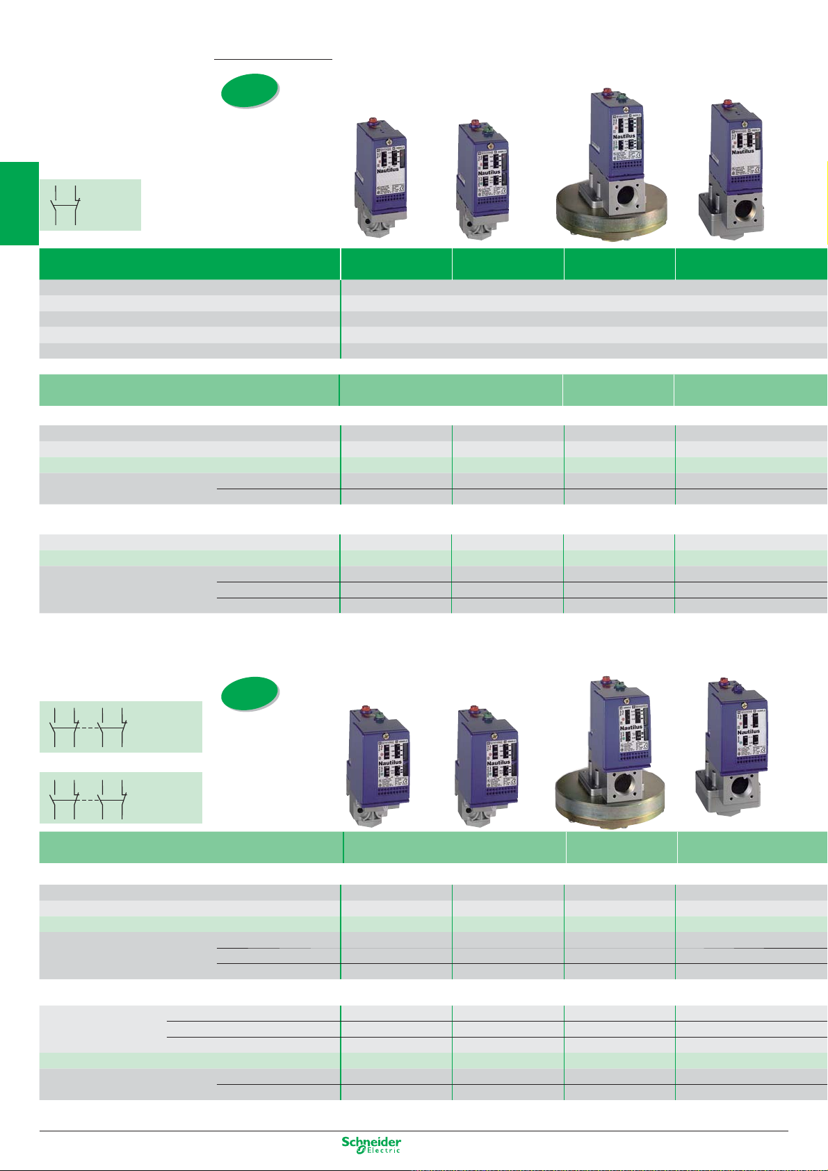
Page 23
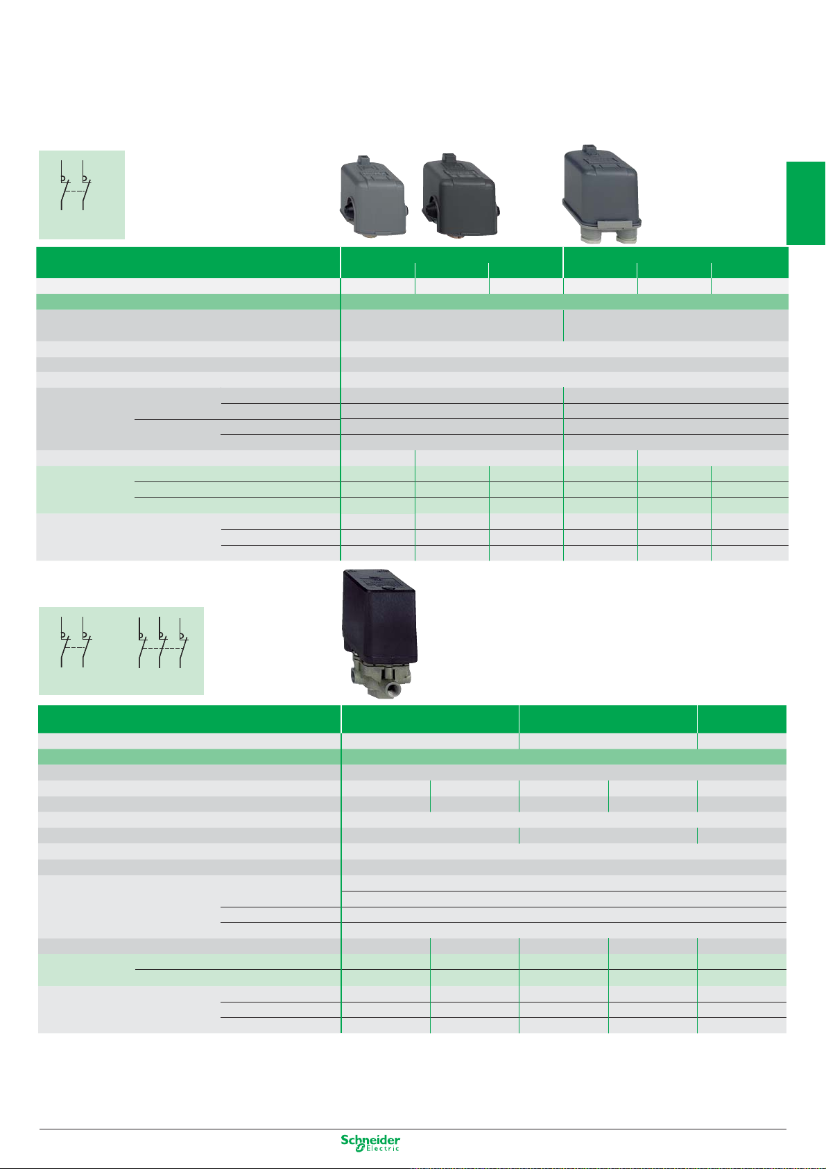
Electromechanical pressure switches
for power circuits, adjustable differential
for regulation between 2 thresholds
12
341234
2 NC 2-pole
contact, snap action
Degree of protection IP 20 IP 65
Size (bar) 4.6 7 10.5 4.6 7 10.5
Setting range of upper limit (PH) (bar) 1.4…4.6 2.8…7 5.6…10.5 1.4…4.6 2.8…7 5.6…10.5
Fluids controlled Water (fresh water, sea water) from 0…+55°C
Electrical connection Screw terminals, 2 cable entries with grommet Screw terminals, 2 tapped entries
for n° 13 (DIN Pg 13.5) cable gland
Product certification
Ambient air temperature For operation: 0…+ 50°C. For storage: - 30…+ 80°C
Rated operational characteristics Ie = 10 A, Ue = 250 V AC
Power rating 110 V AC 2-pole, single-phase 0.75 kW (1 HP) 0.75 kW (1 HP)
of controlled AC 2-pole, 3-phase 1.1 kW (1.5 HP) 1.1 kW (1.5 HP)
motors 230 / 400 V AC 2-pole, single-phase 1.5 kW (2 HP) 1.5 kW (2 HP)
AC 2-pole, 3-phase 2.2 kW (3 HP) 2.2 kW (3 HP)
Dimensions (mm) H x W x D
Fluid connection G 1/4 (BSP female)
R 1/4 (BSP male)
G 3/8 (BSP female) rotating nut
Possible differential (bar) At low setting
subtract from PH to give PB At middle setting
At high setting
CE
96/105 x 72 x 102
FSG2 FYG22 FYG32 FSG2NE FYG22NE FYG32NE
FSG9 FYG29 FYG39 – – –
– – – FSG2NEG – –
1 min. - 2.1 max. 1.2 min. - 2.3 max. 1.9 min. - 3 max. 1 min. - 2.1 max. 1.2 min. - 2.3 max. 1.9 min. - 3 max.
1.1 min. - 2.2 max. 1.4 min. - 2.5 max. 2.1 min. - 3.2 max. 1.1 min. - 2.2 max. 1.4 min. - 2.5 max. 2.1 min. - 3.2 max.
1.2 min. - 2.3 max. 1.6 min. - 2.7 max. 2.3 min. - 3.4 max. 1.2 min. - 2.3 max. 1.6 min. - 2.7 max. 2.3 min. - 3.4 max.
94 x 72 x 102 115 x 72 x 106 115 x 72 x 106
1
2
3
4
5
12
341234
2 NC 2-pole con
tact, snap action
-
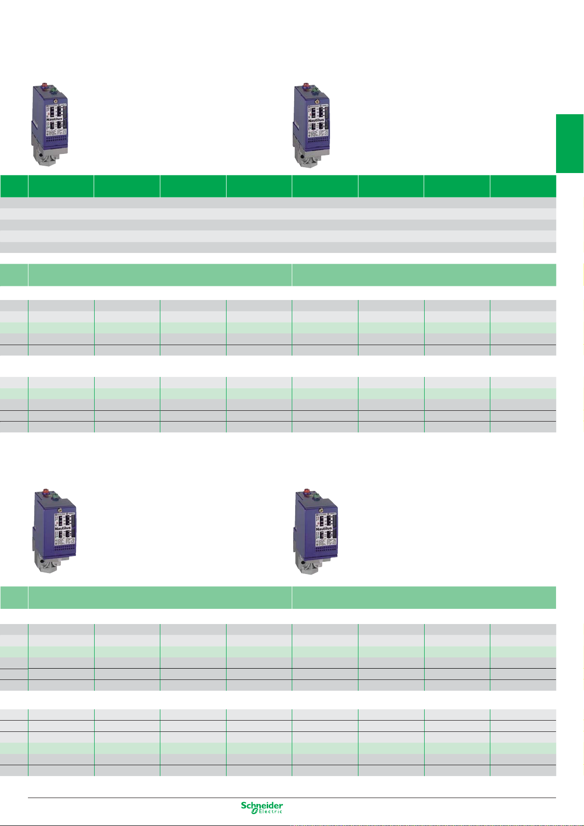
3 NC 3-pole contact, snap action
56
56
12
12
34
34
Size (bar) 6 12 25
Setting range of upper limit (PH) (bar) 1…6 1.3.…12 3.5…25
Fluids controlled Air, water (fresh water, sea water) from 0…+70°C
Ambient air temperature For operation: - 25…+ 70°C. For storage: - 40…+ 70°C
Decompression valve / ONOff knob
Fluid connection G 1/4 (BSP female)
Electrical connection Screw terminals, 2 tapped entries for n° 13 (DIN Pg 13.5) cable gland
Degree of protection IP 54 IP 54 IP 54
Product certification CE - CCC
Rated insulation voltage Ui = 500 V
Electrical Power 1.5 kW 400 V AC 3-phase: 1 000 000 operating cycles
durability 230 V AC 3-phase: 600 000 operating cycles
2.2 kW 400 V AC 3-phase: 700 000 operating cycles
3 kW 400 V AC 3-phase: 500 000 operating cycles
Dimensions (mm) H x W x D 106 x 57 x 97.5 138 x 57 x 97.5 106 x 57 x 97.5 138 x 57 x 97.5 126 x 57 x 97.5
Type of contacts 2 NC 2-pole, snap action contact
3 NC 3-pole, snap action contact
Possible differential (bar) Min. at low setting 0.8 0.8 1 1 3.4
subtract from PH to give PB Min. at high setting
Max. at high setting
without with without with without
4 x G 1/4 (BSP female)
XMPA06B2131 XMPE06B2431 XMPA12B2131 XMPE12B2431 XMPA25B2131
XMPA06C2131 XMPE06C2431 XMPA12C2131 XMPE12C2431 XMPA25C2131
1.2 1.2 1.7 1.7 4.5
4.2 4.2 8.4 8.4 20
G 1/4 (BSP female)
4 x G 1/4 (BSP female)
G 1/4 (BSP female)
6
7
8
9
Other versions: please consult our Customer Care Centre.
10
1/17
Page 24
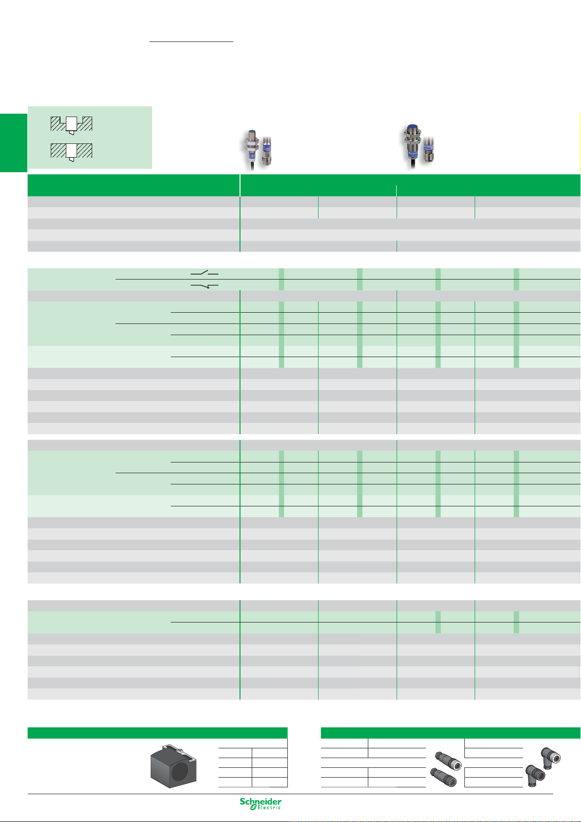
OsiSense XS
Non flush
mountable
Inductive proximity sensors
Cylindrical metal
1
Flush
mountable
Flush standard and increased range
M8 M12
Nominal sensing distance Sn
2
Usable sensing distance S (mm) flush mountable / non flush mountable
Temperature range (°C)
Product certification
Degree of protection (conforming to IEC 60529)
1.5 mm 2.5 mm 2 mm 4 mm
0…1.2 0…2 0…1.6 0…3.2
- 25…+ 70
CE - UL - CSA - CCC (in progress) - C-TICK
IP 67 pre-cabled: IP 69K conforming to DIN 40050, IP 68
Sensors for DC applications
Output function
3
Dimensions (mm) Ø x L Cable / Connector
3-wire
4
2-wire non
polarised (1)
Supply voltage limits, min./max. (V) including ripple
Switching capacity, max. (mA) 3-wire / 2-wire 200 / 100 200 / 100 200 / 100 200 / 100
Overload and short-circuit prot
Residual current, open state (mA) ≤ 0.5 ≤ 0.5 ≤ 0.5 ≤ 0.5
5
Voltage drop, closed state (V) at I nominal 3-wire / 2-wire ≤ 2 / ≤ 4 ≤ 2 / ≤ 4 ≤ 2 / ≤ 4 ≤ 2 / ≤ 4
Switching frequency (Hz) 3-wire / 2-wire 5000 / 4000 2500 / 3000 5000 / 4000 2500 / 2000
Dimensions (mm) Ø x L Cable / connector
3-wire
6
2-wire non
polarised
Supply voltage limits, min./max. (V) including ripple
Switching capacity, max. (mA) 3-wire / 2-wire
7
Overload and short-circuit protection (g) / LED output state indicator
Residual current, open state (mA) 2-wire
Voltage drop, closed state (V) at I nominal 3-wire / 2-wire
Switching frequency (Hz) 3-wire / 2-wire
NO A A A
NC B B B B
M8 x 33 / M8 x 42 M12 x 35 / M12 x 50
PNP
NPN
ection (g) / LED output state indicator
PNP
NPN
Cable (2 m)
Connector M8 / M12
Cable (2m)
Connector M8 / M12
Cable (2 m)
Connecteur M12
Cable (2 m)
Connector M12
Cable (2 m)
Connector M12
Cable (2 m)
Connector M12
XS508B1PAL2 XS108B3PA L2 XS512B1PAL2 XS112B3PAL2
XS508B1PAM8 XS108B3P AM8 XS512B1PAM12 XS112B3PAM12
XS508B1NAL2 XS108B3NAL2 XS512B1NAL2 XS112B3N AL2
XS508B1N
XS508BSC
XS508BSC
10…36 10…36 10…36
(⊗)
g / ⊗ g / ⊗ g / ⊗ g / ⊗
M8 x 51 / M8 x 62 M12 x 53 / M12 x 62
XS508BLPAL2 XS608B1PA L2 XS512BLP A L2 XS612B1PAL2
XS508BLPAM12 XS608B1PAM12 XS512BLP AM12 XS612B1P AM12
XS508BLNAL2 XS608B1NAL2 XS512BLN A L2 XS612B1N AL2
XS508BLN
XS508B1D
XS508B1D
10…58 10…58 10…58 10…58
200 / 100 200 / 100 200 / 100 200 / 100
(⊗)
g / ⊗ g / ⊗ g / ⊗ g / ⊗
≤ 0.5 ≤ 0.5 ≤ 0.5 ≤ 0.5
≤ 2 / ≤ 4 ≤ 2 / ≤ 4 ≤ 2 / ≤ 4 ≤ 2 / ≤ 4
5000 /
A
M8 XS108B3NAM8 XS512B1NAM12 XS112B3NAM12
A
L2 XS608B3CAL2 XS512BSDAL2 XS612B3DAL2
A
L01M12 XS608B3CAL01M12 XS512BSDAM12 XS612B3DAM12
A
M12 XS608B1NAM12 XS512BLNAM12 XS612B1NAM12
A
L2 XS608B1DAL2 XS512B1DAL2 XS612B1DAL2
A
M12 XS608B1DAM12 XS512B1DAM12 XS612B1DAM12
4000 2500 / 3000 5000 / 4000 2500 / 2000
10…36
A
Multi-current/multi-voltage sensors for AC/DC applications
Dimensions (mm) Ø x L Cable / connector
8
2-wire
Supply voltage limits, min./max. (V) including ripple
Switching capacity, max. (mA)
LED output state indicator
Residual current, open state (mA)
9
Voltage drop, closed state (V) at I nominal
Switching frequency (Hz)
(1) polarised for M8 short
(⊗)
Cable (2 m) – – XS512B1M
Connector 1/2"-20 UNF
Accessories
10
Fixing for cylindrical sensors
Fixing clamp with indexing pin
for cylindrical sensors
1/18
M8 XSZB108
M12 XSZB112
M18 XSZB118
M30 XSZB130
– – M12 x 53 / M12 x 62
AL2
– – XS512B1M
– – 20…264 20…264
– – 200 200
––
– – ≤ 0,8 ≤ 0,8
– – ≤ 5.5 ≤ 5.5
– – 25 AC / 1000 DC 25 AC / 1000 DC
⊗⊗
AU20
XS612B1M
XS612B1M
AL2
AU20
Suitable female plug-in connectors
M8 Straight Elbowed
Metal ring
M12 (4 pin)
Metal ring
Plastic ring
XZCC8FDM30S XZCC8FCM30S
XZCC12FDM40B XZCC12FCM40B
XZCC12FDP40B XZCC12FCP40B
Other versions: please consult our Customer Care Centre.
Page 25
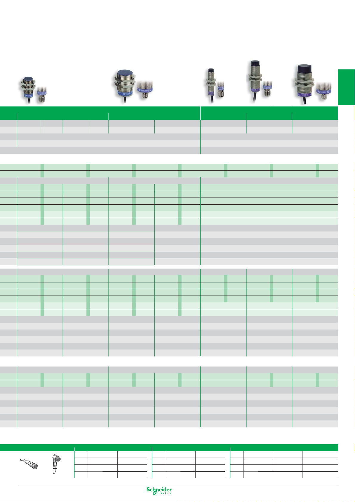
Non flush increased range
M18 M30
5 mm
0…4
- 25…+ 70 - 25…+ 70
CE - UL - CSA - CCC (in progress) - C-TICK CE - UL - CSA - CCC (in progress) - C-TICK
(with connector: IP 67)
8 mm
0…6.4
10 mm
0…8
15 mm 7 mm 12 mm 22 mm
0…12 0…5.6 0…9.6 0…17.6
M12 M18 M30
pre-cabled: IP 69K conforming to DIN 40050, IP 68 (with connector: IP 67)
1
2
AAAAAAA
BBBBBBB
M18 x 39 / M18 x 50 M30 x 43 / M30 x 55
XS518B1PAL2 XS118B3PAL2 XS530B1PA L2 XS130B3P AL2
XS518B1PAM12 XS118B3P AM12 XS530B1P A M12 XS130B3P A M12
XS518B1N AL2 XS118B3NA L2 XS530B1NAL2 XS130B3N AL2
XS518B1N AM12 XS118B3NAM12 XS530B1N A M12 XS130B3N AM12
XS518BSD AL2 XS618B3DA L2 XS530BSD AL2 XS630B3DA L2
XS518BSD AM12 XS618B3D AM12 XS530BSD AM12 XS630B3DAM12
10…36 10…36 10…36
200 / 100 200 / 100 200 / 100 200 / 100
g / ⊗ g / ⊗ g / ⊗ g / ⊗
≤ 0.5 ≤ 0.5 ≤ 0.5 ≤ 0.5
≤ 2 / ≤ 4 ≤ 2 / ≤ 4 ≤ 2 / ≤ 4 ≤ 2 / ≤ 4
2000 / 3000 1000 / 1000 1000 / 2000 500 / 500
M18 x 62 / M18 x 74 M30 x 62
XS518BLPAL2 XS618B1PAL2 XS530BLPAL2 XS630B1P AL2
XS518BLPAM12 XS618B1P AM12 XS530BLP AM12 XS630B1P A M12
XS518BLN AL2 XS618B1N A L2 XS530BLN AL2 XS630B1N AL2
XS518BLN AM12 XS618B1N A M12 XS530BLN A M12 XS630B1N AM12
XS518B1D AL2 XS618B1D A L2 XS530B1D AL2 XS630B1D AL2
XS518B1D AM12 XS618B1D A M12 XS530B1D A M12 XS630B1D AM12
10…58 10…58 10…58 10…58
200 / 100 200 / 100 200 / 100 200 / 100
g / ⊗ g / ⊗ g / ⊗ g / ⊗
≤ 0.5 ≤ 0.5 ≤ 0.5 ≤ 0.5
≤ 2 / ≤ 4 ≤ 2 / ≤ 4 ≤ 2 / ≤ 4 ≤ 2 / ≤ 4
3000 1000 / 1000 1000 / 2000 500 / 500
2000 /
10…36
–
–
–
–
–
–
–
–
–
–
–
–
–
M12 x 55 / M12 x 65 M18 x 62 / M18 x 74 M30 x 62 / M30 x 74
XS612B4PAL2 XS618B4PAL2 XS630B4PAL2
XS612B4PAM12 XS618B4PAM12 XS630B4PAM12
XS612B4NAL2 XS618B4NAL2 XS630B4NAL2
XS612B4NAM12 XS618B4NAM12 XS630B4NAM12
–––
–––
10…58 10…58 10…58
– 200 / – 200 / –
200 /
g / ⊗ g / ⊗ g / ⊗
–––
– ≤ 2 / – ≤ 2 / –
≤ 2 /
2500 / – 1000 / – 500 / –
3
4
5
6
7
M18 x 62 / M18 x 73 M30 x 62 / M30 x 73
XS518B1M AL2 XS618B1M A L2 XS530B1M AL2 XS630B1M A L2
XS518B1M AU20 XS618B1M AU20 XS530B1M AU20 XS630B1MAU20
20…264 20…264 20…264 20…264
300 AC / 200 DC 300 AC / 200 DC 300 AC / 200 DC 300 AC / 200 DC
⊗⊗⊗⊗
≤ 0.8 ≤ 0.8 ≤ 0.8 ≤ 0.8
≤ 5.5 ≤ 5.5 ≤ 5.5 ≤ 5.5
25 AC / 1000 DC 25 AC / 1000 DC 25 AC / 500 DC 25 AC / 500 DC
Pre-wired connectors
Straight Elbowed
M8 (3 pin) 1/2" M12 (4 pin)
Straight Elbowed Straight Elbowed
2 m
XZCP0566L2 XZCP0666L2 2 m XZCP1865L2 XZCP1965L2 2 m XZCP1141L2 XZCP1241L2 XZCP1340L2
XZCP0566L5 XZCP0666L5 5 m XZCP1865L5 XZCP1965L5 5 m XZCP1141L5 XZCP1241L5 XZCP1340L5
5 m
XZCP0566L10 XZCP0666L10 10 m XZCP1865L10 XZCP1965L10 10 m XZCP1141L10 XZCP1241L10 XZCP1340L10
10 m
– M18 x 60 / M18 x 72 M30 x 63 / M30 x 74
–
–
– 20…264 20…264
– 300 AC / 200 DC 300 AC / 200 DC
–
– ≤ 0.8 ≤ 0.8
– ≤ 5.5 ≤ 5.5
– 25 AC / 1000 DC 25 AC / 300 DC
XS618B4MAL2 XS630B4MAL2
A
XS618B4M
⊗⊗
Straight Elbowed Elbowed PNP LED
Other versions: please consult our Customer Care Centre.
U20 XS630B4MAU20
8
9
10
1/19
Page 26

OsiSense XS
Non fl ush
mountable
Inductive proximity sensors
Rectangular plastic
1
Nominal sensing distance Sn
2
Usable sensing distance S (mm) fl ush mountable / non fl ush mountable
Fine adjustment zone (mm) fl ush mountable / non fl ush mountable – – – – –
Suitability for fl ush mounting (metal environment) fl ush mountable fl ush mountable fl ush mountable fl ush mountable fl ush mountable
Temperature range (°C) - 25…+ 70 - 25…+ 70 - 25…+ 70 - 25…+ 70 - 25…+ 70
Product certifi cation CE CE - UL - CSA - C-TICK
Degree of protection (conforming to IEC 60529) pre-cabled: IP 68 (with connector: IP 67)
Flush
mountable
3
Sensors for DC applications
Connection Pre-cabled, PvR (2 m)
2-wire (non polarised) NO or NC programmable –––––
2-wire non
4-wire PNP NO + NC complementary outputs –– –– –
4
3-wire PNP NO function XS7J1A1PAL2 XS7F1A1PAL2 XS7E1A1PAL2 XS7C1A1PAL2 XS7D1A1PAL2
Connection M8 connector M12 connector
5
2-wire non
3-wire PNP NO function
polarised
NPN NO + NC complementary outputs –––––
NPN NO function XS7J1A1NAL2 XS7F1A1NAL2 XS7E1A1NAL2 XS7C1A1NAL2 XS7D1A1NAL2
polarised
NPN NO function
6
Supply voltage limits, min./max. (V) including ripple 10…36 10…36 10…36 10…36 10…36
Switching capacity, max. (mA) 100 100 100 100 100
Short-circuit protect. (g) / LED output
Voltage drop, closed state (V) at I nominal cable / Connector ≤ 4 / ≤ 2 ≤ 4 / ≤ 2 ≤ 2 ≤ 2 ≤ 2
Switching frequency (Hz) cable / Connector 4000 / 2000 5000 / 2000 1000 1000 100
7
Multi-current/multi-voltage sensors for AC/DC applications
Connection
2-wire AC/DC NO function –––––
8
Connection
2-wire AC/DC NO function –––––
Supply voltage limits, min./max. (V) including ripple –––––
Switching capacity, max. (mA) –––––
Short-circuit protect. (g) / LED output
9
Residual current, open state (mA) –––––
Voltage drop, closed state (V) at I nominal –––––
Switching frequency (Hz) –––––
Accessories
10
Fixing for fl at sensors
1/20
NO function XS7J1A1DAL2 XS7F1A1DAL2 XS7E1A1DAL2 XS7C1A1DAL2 XS7D1A1DAL2
NC function XS7J1A1DBL2 XS7F1A1DBL2 XS7E1A1DBL2 XS7C1A1DBL2 XS7D1A1DBL2
NC function XS7J1A1PBL2 XS7F1A1PBL2 XS7E1A1PBL2 XS7C1A1PBL2 XS7D1A1PBL2
NC function XS7J1A1NBL2 XS7F1A1NBL2 XS7E1A1NBL2 XS7C1A1NBL2 XS7D1A1NBL2
NO function
NC function
NC function
NC function
state indicator (⊗) / Power on LED
NC function –––––
AC NO or NC programmable –––––
AC/DC NO or NC programmable ––– ––
NC function –––––
state indicator (⊗) / Power on LED
fl a t
90°
(⊗)
(⊗)
8x22x8 XSZBJ00 XSZBJ90
15x32x8 XSZBF00 XSZBF90
26x26x13
40x40x15 XSZBC00 XSZBC90
U 8 x 22 x 8 U 15 x 32 x 8 U 26 x 26 x 13 U 40 x 40 x 15 U 80 x 80 x 26
2.5 mm 5 mm 10 mm 15 mm 40 mm
0...2 0...4 0…8 0…12 0…32
XS7J1A1DAL01M8 (1) XS7F1A1DAL01M8 (1)
XS7J1A1DBL01M8 (1) XS7F1A1DBL01M8 (1)
XS7J1A1PAL01M8 (1) XS7F1A1PAL01M8 (1)
XS7J1A1PBL01M8 (1) XS7F1A1PBL01M8 (1)
XS7J1A1NAL01M8 (1) XS7F1A1NAL01M8 (1)
XS7J1A1NBL01M8 (1) XS7F1A1NBL01M8 (1)
g / ⊗ / – g / ⊗ / – g / ⊗ / – g / ⊗ / – g / ⊗ / –
–––––
(1) M8 connector on fl ying lead (L = 0.15 m).
XS7E1A1DAM8 XS7C1A1DAM8 XS7D1A1DAM12
XS7E1A1DBM8 XS7C1A1DBM8 XS7D1A1DBM12
XS7E1A1PAM8 XS7C1A1PAM8 XS7D1A1PAM12
XS7E1A1PBM8 XS7C1A1PBM8 XS7D1A1PBM12
XS7E1A1NAM8 XS7C1A1NAM8 XS7D1A1NAM12
XS7E1A1NBM8 XS7C1A1NBM8 XS7D1A1NBM12
Suitable female plug-in connectors
fl at 90°
XSZBE00 XSZBE90
M8 Straight Elbowed
Metal ring XZCC8FDM30S XZCC8FCM30S
M12 (4 pin)
Metal ring XZCC12FDM40B XZCC12FCM40B
Plastic ring XZCC12FDP40B XZCC12FCP40B
Other versions: please consult our Customer Care Centre.
Page 27
U 40 x 40 x 117 U 26 x 26 x 13 U 40 x 40 x 15 U 80 x 80 x 26
1
15 mm
0…12 0…16 0…16 0…32 0…8 / 0...12 0…12 / 0...20 0…32 / 0...48
fl ush mountable non fl ush mountable fl ush mountable or non fl ush mountable via teach mode
- 25…+ 70 - 25…+ 70
CE - UL - CSA - CCC - C-TICK CE - UL - CSA - CCC - C-TICK
IP 67 pre-cabled: IP 68 (with connector: IP 67)
Screw terminals (2) Pre-cabled (2 m)
XS7C40DP210 – XS8C40DP210 – – – –
XS7C40DA210 – XS8C40DA210 – – – –
–––––––
XS7C40PC440 XS7C40PC449 XS8C40PC440 XS8C40PC449 – – –
XS7C40NC440 XS7C40NC449 XS8C40NC440 XS8C40NC449 – – –
– – – – XS8E1A1PAL2 XS8C1A1PAL2 XS8D1A1PAL2
– – – – XS8E1A1PBL2 XS8C1A1PBL2 XS8D1A1PBL2
– – – – XS8E1A1NAL2 XS8C1A1NAL2 XS8D1A1NAL2
– – – – XS8E1A1NBL2 XS8C1A1NBL2 XS8D1A1NBL2
M8 connector M8 connector M12 connector
–––––––
–––––––
– – – – XS8E1A1PAM8 XS8C1A1PAM8 XS8D1A1PAM12
– – – – XS8E1A1PBM8 XS8C1A1PBM8 XS8D1A1PBM12
– – – – XS8E1A1NAM8 XS8C1A1NAM8 XS8D1A1NAM12
– – – – XS8E1A1NBM8 XS8C1A1NBM8 XS8D1A1NBM12
12…48 10…36 10…36 10…36
4-wire version = 200 – 2-wire version = 1.5…100 100 200 200
4-wire version = g / ⊗ / ⊗ – 2-wire version = g / ⊗ / – g / ⊗ / ⊗ g / ⊗ / ⊗ g / ⊗ / ⊗
4-wire version = ≤ 2 – 2-wire version = ≤ 4 ≤ 2 ≤ 2 ≤ 2
2-wire = 1500 / 4-wire = 1000 2-wire = 800 / 4-wire = 1000 (20mm) 500 (40mm) 2000 1000 150
Screw terminals (2) Pre-cabled (2 m)
– – – – XS8E1A1MAL2 XS8C1A1MAL2 XS8D1A1MAL2
– – – – XS8E1A1MBL2 XS8C1A1MBL2 XS8D1A1MBL2
XS7C40FP260 – XS8C40FP260 – – – –
XS7C40MP230 – XS8C40MP230 – – – –
– – – – XS8E1A1MAL01U20 XS8C1A1MAL01U20 XS8D1A1MAU20
– – – – XS8E1A1MBL01U20 XS8C1A1MBL01U20 XS8D1A1MBU20
20…264 20…264 20…264 20…264
AC version = 500 – AC/DC version = 300 / 200 200 AC or DC 300 AC / 200 DC 300 AC / 200 DC
– / ⊗ / – – / ⊗ / ⊗ – / ⊗ / ⊗ – / ⊗ / ⊗
AC version = ≤ 1.5 – AC/DC version = ≤ 0.8 / 1.5 ≤ 1.5 ≤ 1.5 ≤ 1.5
≤ 5.5 ≤ 5.5 ≤ 5.5 ≤ 5.5
25 AC / 50 DC 2000 1000 150
(2) Sensors supplied without cable gland. Suitable cable gland: 13P. Also available in M20, 1/2" NPT output and M12, 7/8" connectors.
20 mm increased range
20 mm
40 mm increased range
15 mm 25 mm 60 mm
5...10 / 5...15 8...15 / 8...25 20...40 / 20...60
1/2"-20 UNF connector
2
3
4
5
6
7
8
9
Pre-wired connectors
Straight
Elbowed
M8 (3 pin) 1/2" M12 (4 pin)
Straight Elbowed Straight Elbowed
2 m XZCP0566L2 XZCP0666L2 2 m XZCP1865L2 XZCP1965L2 2 m XZCP1141L2 XZCP1241L2 XZCP1340L2
5 m XZCP0566L5 XZCP0666L5 5 m XZCP1865L5 XZCP1965L5 5 m XZCP1141L5 XZCP1241L5 XZCP1340L5
10 m XZCP0566L10 XZCP0666L10 10 m XZCP1865L10 XZCP1965L10 10 m XZCP1141L10 XZCP1241L10 XZCP1340L10
Straight Elbowed Elbowed PNP LED
Other versions: please consult our Customer Care Centre.
10
1/21
Page 28
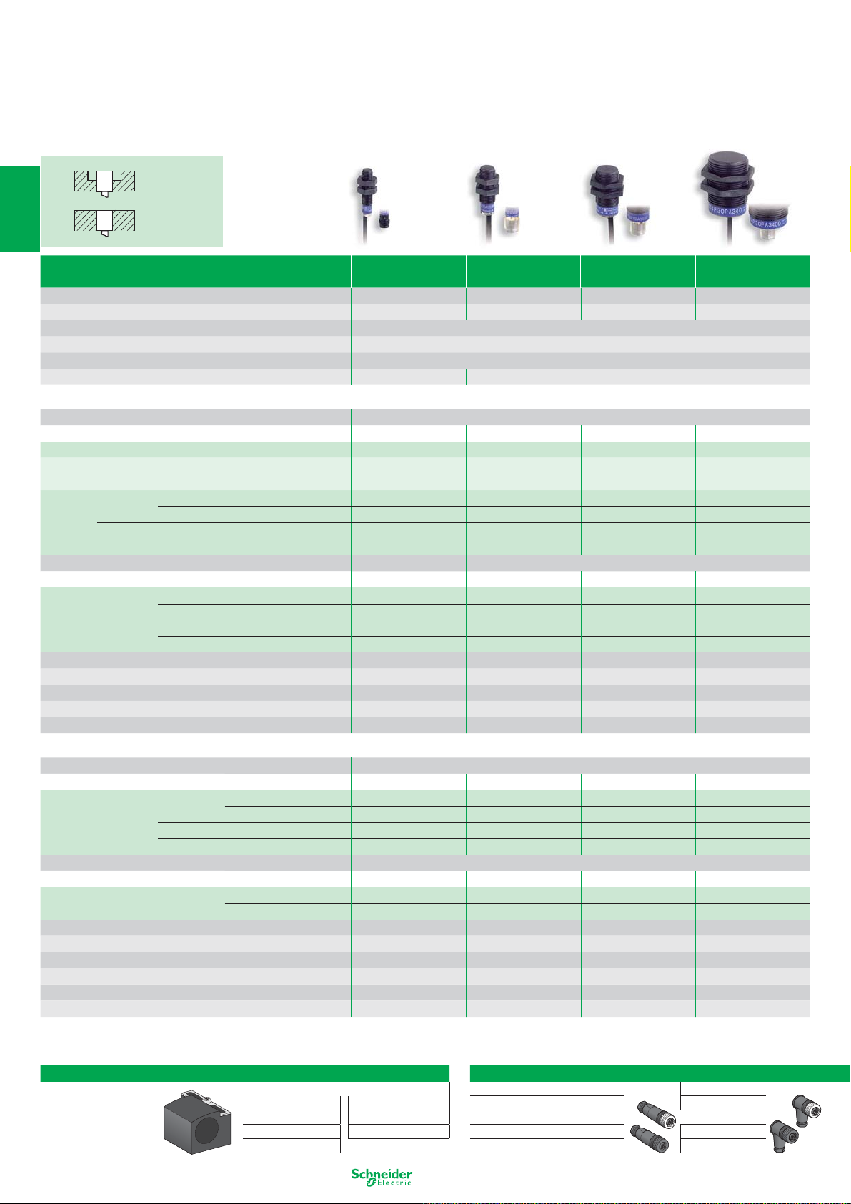
OsiSense XS
Non flush
mountable
Inductive proximity sensors
Cylindrical Plastic
1
Nominal sensing distance Sn
2
Operating zone (mm) 0…2 0…3.2 0…6.4 0…12
Suitability for flush mounting (metal environment) non flush mountable
Temperature range (°C) - 25…+ 70
Product certification CE - UL - CSA - CCC - C-TICK
Degree of protection (conforming to IEC 60529) IP 67 pre-cabled: IP 68 (with connector: IP 67)
Sensors for DC applications
3
Connection Pre-cabled, PvR (2 m)
Dimensions (mm) Ø x L or W x H x D M8 x 33 M12 x 33 M18 x 33.5 M30 x 40.5
2-wire (non polarised) NO or NC programmable ––––
4-wire PNP NO + NC complementary outputs –– ––
NPN NO + NC complementary outputs ––––
3-wire PNP NO function XS4P08PA340 XS4P12PA340 XS4P18PA340 XS4P30PA340
4
NPN NO function XS4P08NA340 XS4P12NA340 XS4P18NA340 XS4P30NA340
Connection M8 connector M12 connector
Dimensions (mm) Ø x L or W x H x D M8 x 42 M12 x 48 M18 x 48 M30 x 50
3-wire PNP NO function XS4P08PA340S XS4P12PA340D XS4P18PA340D XS4P30PA340D
5
NPN NO function XS4P08NA340S XS4P12NA340D XS4P18NA340D XS4P30NA340D
Supply voltage limits, min./max. (V) including ripple
Switching capacity, max. (mA)
Short-circuit protect. (
6
Voltage drop, closed state (V) at I nominal ≤ 2 ≤ 2 ≤ 2 ≤ 2
Switching frequency (Hz)
Flush
mountable
M8 M12 M18 M30
2.5 mm 4 mm 8 mm 15 mm
NC function XS4P08PB340 XS4P12PB340 XS4P18PB340 XS4P30PB340
NC function XS4P08NB340 XS4P12NB340 XS4P18NB340 XS4P30NB340
NC function XS4P08PB340S XS4P12PB340D XS4P18PB340D XS4P30PB340D
NC function XS4P08NB340S XS4P12NB340D XS4P18NB340D XS4P30NB340D
10…38 10…38 10…38 10…38
200 200 200 200
g) / LED output state indicator (⊗) g / ⊗ g / ⊗ g / ⊗ g / ⊗
5000 5000 2000 1000
Multi-current/multi-voltage sensors for AC/DC applications
Connection Pre-cabled, PvR (2 m)
Dimensions (mm) Ø x L or W x D x H M8 x 50 M12 x 50 M18 x 60 M30 x 60
7
2-wire AC/DC NO function XS4P08MA230 XS4P12MA230 XS4P18MA230 XS4P30MA230
not short-circuit protected (1)
AC NO or NC programmable ––––
AC/DC NO or NC programmable ––––
Connection 1/2" connector
Dimensions (mm) Ø x L or W x H x D M8 x 61 M12 x 61 M18 x 70 M30 x 70
8
2-wire AC/DC NO function XS4P08MA230K XS4P12MA230K XS4P18MA230K XS4P30MA230K
not short-circuit protected (1)
Supply voltage limits, min./max. (V) including ripple
Switching capacity, max. (mA)
LED output state indicator (
Residual current, open state (mA) ≤ 0.6 ≤ 0.6 ≤ 0.6 ≤ 0.6
9
Voltage drop, closed state (V) at I nominal ≤ 5.5 ≤ 5.5 ≤ 5.5 ≤ 5.5
Switching frequency (Hz) 25 AC / 3000 DC 25 AC / 3000 DC 25 AC / 2000 DC 25 AC / 1000 DC
(1) For these sensors without short-circuit protection, it is essential to connect a 0.4 A quick-blow fuse in series with the load.
⊗)
NC function XS4P08MB230 XS4P12MB230 XS4P18MB230 XS4P30MB230
NC function XS4P08MB230K XS4P12MB230K XS4P18MB230K XS4P30MB230K
20…264 20…264 20…264 20…264
100 200 300 AC / 200 DC 300 AC / 200 DC
⊗⊗⊗⊗
Accessories
10
Fixing for cylindrical sensors
Fixing clamp with indexing pin
for cylindrical sensors
1/22
M4 XSZB104 M12 XSZB112
M5 XSZB105 M18 XSZB118 M12 (4 pin)
M6.5 XSZB165 M30 XSZB130 Metal ring XZCC12FDM40B XZCC12FCM40B
M8 XSZB108 Plastic ring XZCC12FDP40B XZCC12FCP40B
Suitable female plug-in connectors
M8 Straight Elbowed
Metal ring XZCC8FDM30S XZCC8FCM30S
Other versions: please consult our Customer Care Centre.
Page 29
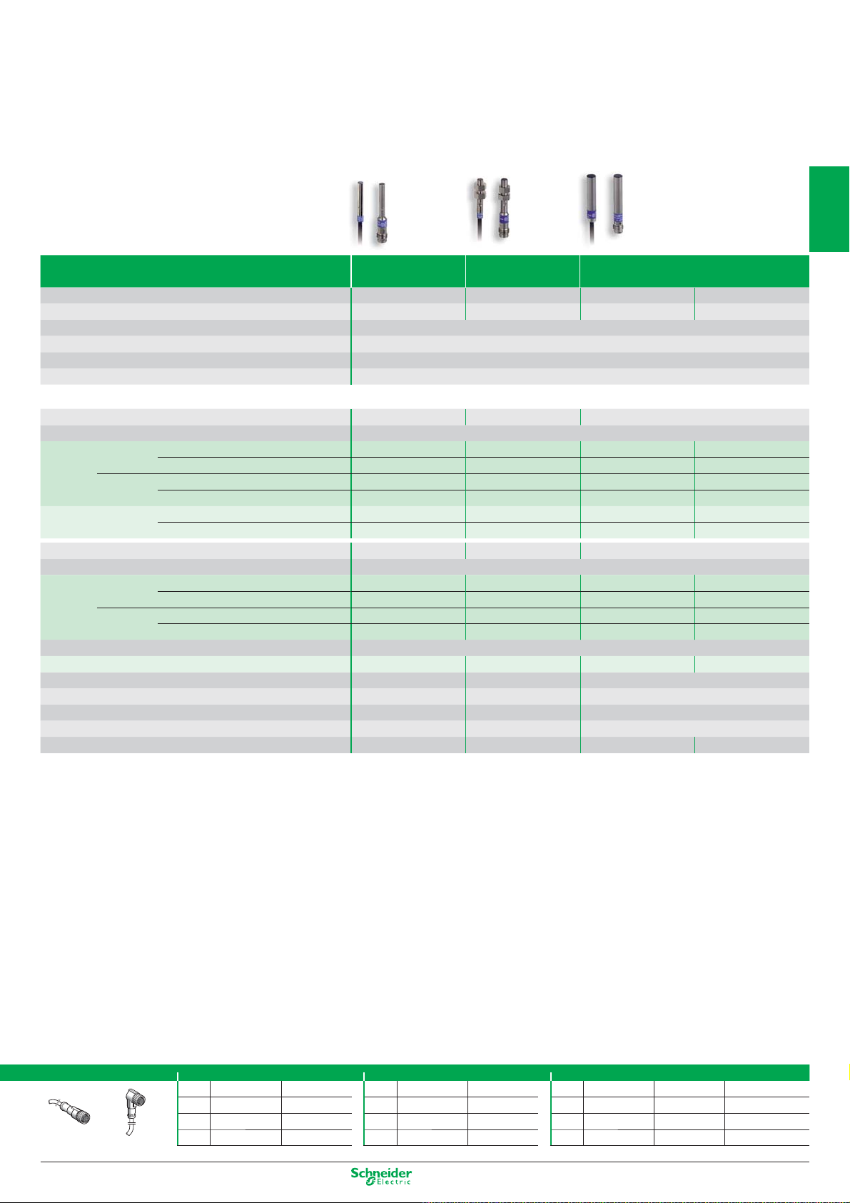
Miniature cylindrical metal (assembly)
Ø 4 M5 Ø 6.5
1
Nominal sensing distance Sn
Operating zone (mm) 0…0.8 0…0.8 0…1.2 0…2
Suitability for flush mounting (metal environment) flush mountable
Temperature range (°C) - 25…+ 70
Product certification CE - UL - CSA - CCC - C-TICK
Degree of protection (conforming to IEC 60529) IP 67
1 mm 1 mm 1.5 mm 2.5 mm
Sensors for DC applications
Dimensions (mm) Ø x L Ø 4 x 29 M5 x 29 Ø 6.5 x 33
Connection Pre-cabled, PvR (2 m)
3-wire PNP NO function XS1L04PA310 XS1N05PA310 XS506B1PAL2 XS106B3PAL2
NC function – – XS506B1PBL2 XS106B3PBL2
NPN NO function XS1L04NA310 XS1N05NA310 XS506B1NAL2 XS106B3NAL2
NC function – – XS506B1NBL2 XS106B3NBL2
2-wire (polarised) NO function – – XS506BSCAL2 XS606B3CAL2
NC function – – XS506BSCBL2 XS606B3CBL2
Dimensions (mm) Ø x L Ø 4 x 41 M5 x 41 Ø 6.5 x 42
Connection M8
3-wire PNP NO function XS1L04PA310S XS1N05PA311S (1) XS506B1PAM8 XS106B3PAM8
NC function – – XS506B1PBM8 XS106B3PBM8
NPN NO function XS1L04NA310S XS1N05NA311S (1) XS506B1NAM8 XS106B3NAM8
NC function – – XS506B1NBM8 XS106B3NBM8
Connection M12
2-wire (polarised) fonction NO – – XS506BSCAL01M12 XS506B3CAL01M12
Supply voltage limits, min./max. (V) including ripple
Switching capacity, max. (mA) 3-wire / 2-wire 100 / – 100 / – 200 / 100
Short-circuit protect. (
Voltage drop, closed state (V) at I nominal 3-wire / 2-wire ≤ 2 / – ≤ 2 / – ≤ 2 / ≤ 4
Switching frequency (Hz) 3-wire / 2-wire 5000 / – 5000 / – 5000 / 4000 2500 / 3000
(1) Stainless steel sensors, Sn = 0.8 mm
g) / LED output state indicator (⊗) g / ⊗ g / ⊗ g / ⊗
5…30 5…30 10…36
2
3
4
5
6
Pre-wired connectors
Straight
Elbowed
M8 (3 pin) 1/2" M12 (4 pin)
Straight Elbowed Straight Elbowed
2 m
XZCP0566L2 XZCP0666L2 2 m XZCP1865L2 XZCP1965L2 2 m XZCP1141L2 XZCP1241L2 XZCP1340L2
XZCP0566L5 XZCP0666L5 5 m XZCP1865L5 XZCP1965L5 5 m XZCP1141L5 XZCP1241L5 XZCP1340L5
5 m
XZCP0566L10 XZCP0666L10 10 m XZCP1865L10 XZCP1965L10 10 m XZCP1141L10 XZCP1241L10 XZCP1340L10
10 m
Straight Elbowed Elbowed PNP LED
Other versions: please consult our Customer Care Centre.
7
8
9
10
1/23
Page 30
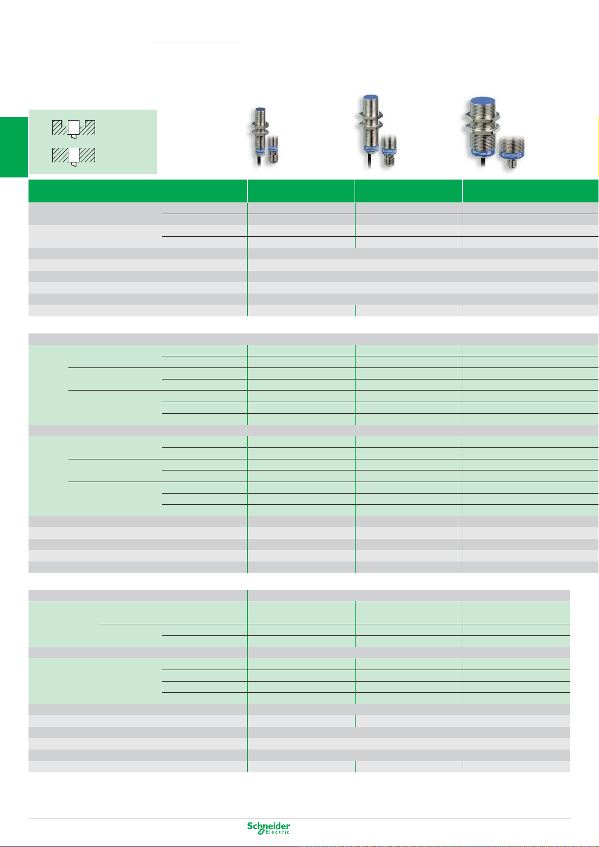
OsiSense XS
Non flush
mountable
Inductive proximity sensors
Multi-voltage with short-circuit protection
1
Sensing distance Sn flush mountable
2
Operating zone (mm)
Suitability for flush mounting (metal environment) flush mountable or non flush mountable depending on model
Case M (metal) P (plastic)
Temperature range (°C) - 25…+ 70
3
Degree of protection (conforming to IEC 60529) IP 68 (with connector: IP 67)
Product certification CE - UL - CSA - CCC - C-TICK
Dimensions (mm) Ø x L Cable (Connector) M12 x 55 (M12 x 66) M18 x 60 (M18 x 72) M30 x 60 (M30 x 72)
Flush
mountable
non flush mountable
flush mountable
non flush mountable
M12 M18 M30
2 mm 5 mm 10 mm
4 mm 8 mm 15 mm
0…1.6 0…4 0…8
0…3.2 0…6.4 0…12
M
Sensors for DC applications
Connection
4-wire PNP NO + NC flush mountable –––
4
non flush mountable
NPN NO + NC flush mountable –––
non flush mountable
PNP+NPN NO/NC flush mountable (metal) –– –
programmable non flush mntbl. (metal) –––
5
Connection
4-wire PNP NO + NC flush mountable –––
NPN NO + NC flush mountable –––
6
Supply voltage limits, min./max. (V) including ripple
Switching capacity, max. (mA)
Short-circuit protection (
Voltage drop, closed state (V) at I nominal
7
Switching frequency (Hz)
PNP+NPN NO/NC flush mountable (metal) –– –
programmable non flush mntbl. (metal) –––
g) / LED output state indicator (⊗) –––
non flush mntbl. (plastic)
non flush mountable
non flush mountable
non flush mntbl. (plastic)
–––
–––
–––
–––
–––
–––
–––
–––
–––
–––
Multi-current/multi-voltage sensors for AC/DC applications
Connection Pre-cabled, PvR (2 m)
2-wire AC/DC NO function flush mountable XS1M12MA250 XS1M18MA250 XS1M30MA250
8
Connection 1/2"-20 UNF connector
2-wire AC/DC NO function flush mountable XS1M12MA250K XS1M18MA250K XS1M30MA250K
NC function flush mountable XS1M12MB250 XS1M18MB250 XS1M30MB250
NC function flush mountable XS1M12MB250K XS1M18MB250K XS1M30MB250K
9
Supply voltage limits, min./max. (V) 50-60 Hz
Switching capacity, max. (mA)
LED output state indicator (
Residual current, open state (mA) ≤ 1.5
10
Voltage drop, closed state (V) at I nominal ≤ 5.5
Switching frequency (Hz) 25 AC, 4000 DC 25 AC, 2000 DC 25 AC, 2000 DC (1)
(1) 25 AC, 1000 DC for non flush mountable Ø 30 mm.
1/24
⊗) / Power on LED (⊗) ⊗ / ⊗
non flush mountable
non flush mountable
non flush mountable
non flush mountable
XS2M12MA250 XS2M18MA250 XS2M30MA250
XS2M12MB250 XS2M18MB250 XS2M30MB250
XS2M12MA250K XS2M18MA250K XS2M30MA250K
XS2M12MB250K XS2M18MB250K XS2M30MB250K
20…264
5…200 5…200 AC, 5…300 DC
Other versions: please consult our Customer Care Centre.
Page 31

PNP or NPN
NO + NC Complementary outputs
M8 M12 M18 M30 M12 M18 M30
PNP + NPN outputs,
NO or NC programmable
1
1.5 mm 2 mm 5 mm 10 mm 2 mm 5 mm 10 mm
2.5 mm 4 mm 8 mm 15 mm 4 mm 8 mm 15 mm
0…1.2 0…1.6 0…4 0…8 0…1.6 0…4 0…8
0…2 0…3.2 0…6.4 0…12 0…3.2 0…6.4 0…12
flush mountable or non flush mountable depending on model flush mountable or non flush mountable depending on model
M M or P depending on model
- 25…+ 70 - 25…+ 70
IP 67 IP 68 (with connector: IP 67) IP 68 (with connector: IP 67)
CE - UL - CSA - CCC - C-TICK CE - UL - CSA - CCC - C-TICK
M8 x 50 (M8 x 61) M12 x 33 (M12 x 48) M18 x 36.5 (M18 x 49) M30 x 40.5 (M30 x 53) M12 x 50 (M12 x 61) M18 x 60 (M18 x 72) M30 x 60 (M30 x 72)
Pre-cabled, PvR (2 m) Pre-cabled, PvR (2 m)
XS1M08PC410 XS1N12PC410 XS1N18PC410 XS1N30PC410 – – –
XS2M08PC410 XS2N12PC410 XS2N18PC410 XS2N30PC410 – – –
XS1NM08NC410 XS1N12NC410 XS1N18NC410 XS1N30NC410 – – –
XS2M08NC410 XS2N12NC410 XS2N18NC410 XS2N30NC410 –
– – – – XS1M12KP340 XS1M18KP340 XS1M30KP340
– – – – XS2M12KP340 XS2M18KP340 XS2M30KP340
– – – – XS4P12KP340 XS4P18KP340 XS4P30KP340
M12 connector M12 connector
XS1M08PC410D XS1N12PC410D XS1N18PC410D XS1N30PC410D – – –
XS2M08PC410D XS2N12PC410D XS2N18PC410D XS2N30PC410D – – –
XS1M08NC410D XS1N12NC410D XS1N18NC410D XS1N30NC410D – – –
XS2M08NC410D XS2N12NC410D XS2N18NC410D XS2N30NC410D – – –
– – – – XS1M12KP340D XS1M18KP340D XS1M30KP340D
– – – – XS2M12KP340D XS2M18KP340D XS2M30KP340D
– – – – XS4P12KP340D XS4P18KP340D XS4P30KP340D
10…36 10…36
200 200
g / ⊗ g / –
≤ 2 ≤ 2.6
5000 5000 2000 1000 5000 2000 1000
2
3
4
5
6
7
PNP NPN
PNP
NO
NC
+
NPN
–
NO
NC
Accessories
Fixing clamps
With indexing pin for cylindrical sensors length 5 m
M8 XSZB108
M12 XSZB112 M8 (or S) XZCP0666L5 XZCP0566L5 XZCC8FCM30S
M18 XSZB118 M12 (or D) XZCP1241L5 XZCP1141L5 XZCC12FCM40B
M30 XSZB130 1/2" (or K) XZCP1965L5 XZCP1865L5 XZCC20FCM30B
Suitable female plug-in connectors, including pre-wired versions
without LED
NO NC
+
NPN
PNP
–
pre-wired,
elbowed
+ BN/1
- BU/3
pre-wired,
straight
NPN
PNP
screw terminal
+ BU/3
8
- BN/1
9
10
Other versions: please consult our Customer Care Centre.
1/25
Page 32

OsiSense XS
1
Non flush
mountable
Flush
mountable
Inductive proximity sensors - Application
Rotation control
26 x 26 x 13 40 x 40 x 15 M30 M18 M30
Fixed sensing distance
(for ferrous or non ferrous materials)
Nominal sensing distance Sn
2
Operating zone (mm) 0...8 0...12 0...8 0...4 0...8
Suitability for flush mounting (metal environment) flush mountable flush mountable
Case M (metal) P (plastic)
Temperature range (°C) - 25…+ 70 0…+ 50
Degree of protection (conforming to IEC 60529) IP 67 pre-cabled: IP 68 (with connector: IP 67)
Product certification CE - UL - CSA - CCC - C-TICK CE - UL - CSA - CCC - C-TICK
3
Dimensions (mm) Ø x L or W x H x D Cable (Connector) 26 x 26 x 13 40 x 40 x 15 M30 x 81
Maximum speed of passing object (impulses/min)
Adjustable frequency range (impulses/min)
10 mm 15 mm 10 mm 5 mm 10 mm
PP M MM
M18 x 60 (M18 x 70)
48000 48000 6000...48000 (1) – –
6...6000 6...6000
6...150 / 120...3000 (1)
––
Sensors for DC applications
Connection Pre-cabled, PvR (2 m)
4
4-wire PNP/NPN NO/NC programmable – – – XS1M18KPM40 XS1M30KPM40
3-wire PNP NC function slow version – – XSAV11373 – –
fast version
0…10 V output plastic –– – ––
4…20 mA output metal, flush mountable –– – ––
5
Connection M8 or M12 connector
4-wire PNP/NPN NO/NC programmable – – – XS1M18KPM40D XS1M30KPM40LD
3-wire PNP NC function
0…10 V output – – – – –
6
Supply voltage limits, min./max. (V) including ripple
Switching capacity, max. (mA)
Short-circuit protect. (g) / LED output state indicator (⊗) / Power on LED (⊗)
Linearity error
Voltage drop, closed state (V) at I nominal
Switching frequency (Hz)
7
Operating frequency (Hz)
4…20 mA output – – – – –
plastic, flush mountable
plastic, non flush mountable
– – XSAV12373 – –
–– – ––
–– – ––
XS9E11RPBL01M12 (3) XS9C11RPBL01M12 (3)
10...36 10...36 10...58 10...38
100 200 200 200
(⊗) g / ⊗ / ⊗ g / ⊗ / ⊗ g / ⊗ / – g / ⊗ / –
–– – –
≤ 2 ≤ 2 ≤ 2 ≤ 2.6
– – – 1000
–– – –
–––
M30 x 60
M12 on 0.8 m flying lead
Multi-current/multi-voltage sensors for AC/DC applications
Connection Pre-cabled, PvR (2 m)
2-wire AC/DC NC function
not short-circuit protected (2)
8
Supply voltage limits, min./max. (V) 50-60 Hz
Switching capacity, max. (mA)
LED output state indicator (
Residual current, open state (mA)
Voltage drop, closed state (V) at I nominal
9
Switching frequency (Hz)
NC function slow version – – XSAV11801 – –
fast version
⊗) / Power on LED (⊗) ⊗ / ⊗⊗ / ⊗⊗ / –
Accessories
Fixing
for flat sensors substitution
10
flat
1/26
90°
XS9E11RMBL01U20 (5) XS9C11RMBL01U20 (5)
– – XSAV12801 – –
20...264 20...264 20...264 – –
100 300 AC / 200 DC 300 AC / 200 DC – –
≤ 1.5 ≤ 1.5 ≤ 1.5
≤ 5.5 ≤ 5.5 ≤ 5.7
–– – ––
flat 90° sensors
8x22x8 XSZBJ00 XSZBJ90 –
15x32x8 XSZBF00 XSZBF90 XSZBE10
26x26x13 XSZBE00 XSZBE90 XSZBC10
40x40x15 XSZBC00 XSZBC90 XSZBD10
–––
––
––
––
Fixing clamp with indexing pin
of block type
XSE / XSC / XSD
Other versions: please consult our Customer Care Centre.
for cylindrical sensors
M12 XSZB112
M18 XSZB118
M30 XSZB130
Page 33

Analogue (Position control)
8 x 32 x 8 26 x 26 x 13 40 x 40 x 15 80 x 80 x 26 M12 M18 M30
1
5 mm 10 mm 15 mm 40 mm M: 2 mm / P: 4 mm M: 5 mm / P: 8 mm M: 10 mm / P: 15 mm
1...4 1...10 2...15 5...40 M: 0.2…2 / P: 0.4…4 M: 0.5…5 / P: 0.8…8 M: 1…10 / P: 1.5…15
flush mountable flush mountable flush mountable flush mountable
P P P P M or P M or P M or P
- 25…+ 60 - 25…+ 70 - 25…+ 70 - 25…+ 70 - 25…+ 70 - 25…+ 70 - 25…+ 70
pre-cabled: IP 68 (with connector: IP 67) IP 67
CE - UL - CSA - CCC - C-TICK
15 x 32 x 8 26 x 26 x 13 40 x 40 x 15 80 x 80 x 26 Ø 12 x 50 Ø 18 x 50 Ø 30 x 52.5
–––––––
–––––––
–––––––
–––––––
–––––––
XS9F111A1L2
– – – – XS1M12AB120 XS1M18AB120 XS1M30AB120
XS9F111A2L2 XS9E111A2L2 XS9C111A2L2 XS9D111A2L2 – – –
– – – – XS4P12AB120 XS4P18AB120 XS4P30AB120
M8 or M12 connector
–––––––
–––––––
XS9F111A1L01M8 (4) XS9E111A1L01M12 (4) XS9C111A1L01M12 (4) XS9D111A1M12 – – –
XS9F111A2L01M8 (4) XS9E111A2L01M12 (4) XS9C111A2L01M12 (4) XS9D111A2M12 – – –
10...36 10...36 10...36 10...36 10…38 10…38 10…38
–––––––
–––––––
± 1 V for 0…10 V version / ± 2 mA for 4…20 mA version
–––––––
–––––––
2000 1000 1000 100 1500 500 300
(1) 6...150 and 6000 impulses/min for XSAV11373 and XSAV11801 (slow version); 120...3000 and 48000 impulses/min for XSAV12373 and XSAV12801 (fast version).
(2) For these sensors without short-circuit protection, it is essential to connect a 0.4 A quick-blow fuse in series with the load.
(3) Flying lead (L = 0.15 m) with end mounted remote control incorporating M12 connector.
(4) Flying lead (L = 0.15 m) with end connector.
(5) Flying lead (L = 0.15 m) with end mounted remote control incorporating 1/2"-20 UNF connector.
XS9E111A1L2 XS9C111A1L2 XS9D111A1L2 XS4P12AB110 XS4P18AB110 XS4P30AB110
flush / non flush mountable flush / non flush mountable flush / non flush mountable
2
3
4
5
6
7
8
Accessories
Pre-wired connectors
Straight Elbowed
Suitable female plug-in connectors
M8 Straight Elbowed
Steel ring
M12 (4 pin)
Steel ring
Plastic ring
XZCC8FDM30S XZCC8FCM30S
XZCC12FDM40B XZCC12FCM40B
XZCC12FDP40B XZCC12FCP40B
M8 (3 pin) 1/2" M12 (4 pin)
Straight Elbowed Straight Elbowed
2 m
XZCP0566L2 XZCP0666L2 2 m XZCP1865L2 XZCP1965L2 2 m XZCP1141L2 XZCP1241L2 XZCP1340L2
XZCP0566L5 XZCP0666L5 5 m XZCP1865L5 XZCP1965L5 5 m XZCP1141L5 XZCP1241L5 XZCP1340L5
5 m
XZCP0566L10 XZCP0666L10 10 m XZCP1865L10 XZCP1965L10 10 m XZCP1141L10 XZCP1241L10 XZCP1340L10
10 m
Straight Elbowed Elbowed PNP LED
9
10
Other versions: please consult our Customer Care Centre.
1/27
Page 34

OsiSense XS
Inductive proximity sensors - Application
Food and beverage processing
1
Type M12 M18 Ø 18 plain M30
Nominal sensing distance Sn
2
Operating zone (mm) 0 …5.6 0 … 9.6 0 … 9.6 0 … 17.6
Suitability for flush mounting (metal environment) non flush mountable
Case M (metal) (1) M stainless steel 316 L
Product certification CE - UL - CSA - CCC - C-TICK
Temperature range (°C) - 25…+ 85
Degree of protection (conforming to IEC 60529) pre-cabled: IP 68 (with connector: IP 67) and IP 69K conforming to DIN 40050
3
7 mm 12 mm 12 mm 22 mm
Sensors for DC applications (solid-state output: transistor)
Connection Pre-cabled, non poisonous PVC (2 m)
Dimensions (mm) M12 x 55 M18 x 60 Ø 18 x 60 M30 x 62
3-wire PNP NO function XS212SAPAL2 XS218SAPAL2 XS2L2SAPAL2 XS230SAPAL2
4
Connection M12 connector
Dimensions (mm) M12 x 61 M18 x 70 Ø 18 x 70 M30 x 70
3-wire PNP NO function XS212SAPAM12 XS218SAPAM12 XS2L2SAPAM12 XS230SAPAM12
Supply voltage limits, min./max. (V) including ripple
Switching capacity, max. (mA)
5
Switching frequency (Hz)
Short-circuit protection (
Voltage drop, closed state (V) at I nominal
NPN NO function XS212SANAL2 XS218SANAL2 XS2L2SANAL2 XS230SANAL2
NPN NO function XS212SANAM12 XS218SANAM12 XS2L2SANAM12 XS230SANAM12
10…36
≤ 200
2500 1000 1000 500
g) / LED output state indicator (⊗) g / ⊗ g / ⊗ g / ⊗ g / ⊗
≤ 2
Multi-current/multi-voltage sensors for AC/DC applications
Connection Pre-cabled, non poisonous PVC (2 m)
6
Dimensions (mm)
2-wire (2) AC/DC NO function – XS218SAMAL2 – XS230SAMAL2
Connection 1/2"-20 UNF connector
Dimensions (mm)
2-wire (2) AC/DC NO function – XS218SAMAU20 – XS230SAMAU20
Supply voltage limits, min./max. (V) 50-60 HZ
7
Switching capacity, max. (mA)
Switching frequency (Hz)
LED output state indicator (
Voltage drop, closed state (V) at I nominal
Residual current, open state (mA)
8
⊗)
(1) Plastic range available. M12, M18, M30: (2) For these sensors without short-circuit protection, it is essential to connect a
To order, replace the second letter
(example: XS212
SAPAL2 becomes XS212AAPAL2).
S in the reference by A 0.4 A quick-blow fuse in series with the load.
– M18 x 60 – M30 x 62
– M18 x 72 – M30 x 74
– 20 … 264 – 20 … 264
– 300 AC / 200 DC – 300 AC / 200 DC
– 25 AC / 1000 DC – 25 AC / 300 DC
–
–
–
⊗
≤ 5.5
≤ 0.8
–
–
–
⊗
≤ 5.5
≤ 0.8
9
10
Accessories
Fixing clamps M12 pre-wired connector M12 jumper cable
Plastic fixing centres 24.1 mm, with locking screw female, 4-pin, stainless steel clamping ring male, 3-pin, stainless steel clamping ring
for sensor Straight connector 5 m cable
Ø 18 plain
Stainless steel Elbowed connector 5 m cable XZCPA1241L5
for sensor
Ø 12
Ø 18
Ø 30
1/28
XUZB2005
XSZBS12
XUZA118
XSZBS30
XZCPA1141L5 Straight connector 5 m XZCRA151140A5
1/2" pre-wired connector
Straight 5 m XZCP1865L5
Elbowed 5 m XZCP1965L5
Other versions: please consult our Customer Care Centre.
Page 35

OsiSense XT
Non flush mountable
(plastic)
Capacitive proximity sensors
Detection of insulating materials or
conductive materials
Flush mountable
(metal)
Nominal sensing distance Sn flush mountable
Operating zone Sa (mm) (2) flush mountable 0…1.44 0…3.6 0…7.2 0…10 0…11
Case M (metal) P (plastic) flush mountable
Product certification
Temperature range (°C) - 25…+ 70
Degree of protection (conforming to IEC 60529) IP 67
Dimensions (mm) Ø x L or H x W x D M12 x 70 M18 x 80 M30 x 80 M32 x 80 117 x 40 x 40
Suitability for flush
non flush mountable
non flush mountable
non flush mountable
mtg.
M12 M18 M30 Ø 32 40 x 40 x 117
2 mm 5 mm 10 mm 15 mm 15 mm
–8 mm 15 mm 20 mm –
– 0…5.8 0…11 0…15 –
MMM MP
–PPP–
CE CE - UL - CSA
Sensors for DC applications
Connection Pre-cabled, PVC (2 m)
3-wire PNP NO function flush mountable XT112S1PAL2 XT118B1PAL2 XT130B1PAL2 – –
non flush mountable
NO + NC functions flush mountable XT112S1PCL2 XT118B1PCL2 XT130B1PCL2 – –
non flush mountable
NPN NO function flush mountable XT112S1NAL2 XT118B1NAL2 XT130B1NAL2 – –
Connection M12 connector Screw terminals
3-wire PNP NO + NC functions flush mountable XT112S1PCM12 XT118B1PCM12 XT130B1PCM12 – XT7C40PC440 (3)
NPN NO + NC functions flush mountable – – – – XT7C40NC440 (3)
Supply voltage limits, min./max. (V) including ripple
Switching capacity, max. (mA)
Short circuit-protection (
Voltage drop, closed state (V) at I nominal
Switching frequency (Hz)
g) / LED output state indicator (⊗) g / ⊗ g / ⊗
non flush mountable
non flush mountable
– XT218A1PAL2 XT230A1PAL2 – –
––– ––
– XT218A1NAL2 XT230A1NAL2 – –
– XT218A1PCM12 XT230A1PCM12 – –
10...38 10...58
200 200
≤ 2 ≤ 2
300
100 (XT2) / 200 (XT1) 100 (XT2) / 150 (XT1)
– 100
1
2
3
4
5
6
Multi-current/multi-voltage sensors for AC applications
Connection Pre-cabled, PVC (2 m)
2-wire AC (1) NO function flush mountable – XT118B1FAL2 XT130B1FAL2 XT132B1FAL2 –
non flush mountable
NO function flush mountable – XT118B1FBL2 XT130B1FBL2 XT132B1FBL2 –
non flush mountable
Connection Screw terminals
2-wire AC (1) NO or NC
Supply voltage limits, min./max. (V) 50-60 Hz
Switching capacity, max. (mA)
LED output state indicator (
Voltage drop, closed state (V) at I nominal
Switching frequency (Hz)
(1) For these sensors without short-circuit protection, it is essential to connect a 0.4 A quick-blow fuse in series with the load.
(2) The operating distance depends on the objet material.
(3) Only for detecting insulating materials.
programmable
⊗) / Power on LED (⊗) ⊗ / –
flush mountable – – – – XT7C40FP262
– XT218A1FAL2 XT230A1FAL2 XT232A1FAL2 –
– – XT230A1FBL2 XT232A1FBL2 –
– 20…264 20…264 20…264 20…264
– 300 350
–
–25252525
≤ 5.5 ≤ 5.5 ≤ 9 ≤ 5.5
Accessories
Suitable female plug-in connectors, including pre-wired versions
length 5 m pre-wired, pre-wired, screw terminal
without LED
M12 XZCP1241L5 XZCP1141L5 XZCC12FCM40B
elbowed straight
Other versions: please consult our Customer Care Centre.
7
8
9
10
1/29
Page 36

OsiSense XU
Photo-electric sensors
General Purpose
NO function: Object present / Output ON
Thru-beam Refl ex Diffuse
(T) (R) (T/R) (T/R)
NC function: No object present / Output ON
Thru-beam Refl ex Diffuse
1
(T) (R) (T/R) (T/R)
M18 Metal (1) M18 Plastic
Cable M12 connector Cable M12 connector
Diffuse Sensing distance
2
Refl ex Polarised Sensing distance
3
Refl ex Sensing distance (4)
Thru beam Sensing distance
4
Output function
Thru beam Transmitter
Output type DC3 NO
AC/DC 1C/O relay ––––
Output type DC3 NO
AC/DC 1C/O relay ––––
Output type DC3 NO
AC/DC 1C/O relay ––––
Output type DC3 NO
AC/DC 1C/O relay ––––
NO AAAA
NC BBBB
5
Multimode Sensing distance
Output type DC3 NO/NC
6
Thru beam Transmitter
(1) Brass metal, aivailable also in stainless steel, see page food/beverage processing series
(2) For a sensing distance 0,1 m without sensitivity adjustment, change digit 5 by 4 into the reference (ex: XUB5BPANL2 becomes XUB4BPANL2)
Fixing M18 x1 M18 x1
7
Dimensions M18 x 64 mm / M18 x 78 mm
Product certifi cations CE, UL, CSA, C-Tick CE, UL, CSA, C-Tick
DC common characteristics
Supply voltage limits, min./max. (V) including ripple
Switching frequency (Hz)
8
AC/DC common characteristics
Common characteristics for DC versions
Supply voltage limits, min./max. (V) including ripple
Switching frequency (Hz)
LED output state indicator (⊗) / power on LED (⊗)
AC/DC 1C/O relay ––––
PNP XUB5BPANL2 XUB5BP ANM12 XUB5AP A NL2 XUB5AP ANM12
NPN XUB5BN ANL2 XUB5BN ANM12 XUB5ANANL2 XUB5AN ANM12
(4)
PNP XUB9BPANL2 XUB9BP ANM12 XUB9AP ANL2 XUB9AP ANM12
NPN XUB9BN ANL2 XUB9BN ANM12 XUB9ANANL2 XUB9AN ANM12
PNP XUB1BPANL2 XUB1BP ANM12 XUB1AP ANL2 XUB1AP ANM12
NPN XUB1BN ANL2 XUB1BN ANM12 XUB1ANANL2 XUB1AN ANM12
PNP XUB2BPANL2R XUB2BP ANM12R XUB2AP ANL2R XUB2AP ANM12R
NPN XUB2BN ANL2R XUB2BN ANM12R XUB2AN ANL2R XUB2AN ANM12R
DC XUB2BKSNL2T XUB2BKSNM12T XUB2AKSNL2T XUB2AKSNM12T
AC/DC ––– –
PNP XUB0BPSNL2 XUB0BPSNM12 XUB0APSNL2 XUB0APSNM12
NPN XUB0BNSNL2 XUB0BNSNM12 XUB0ANSNL2 XUB0ANSNM12
PNP/NPN ––––
DC XUB0BKSNL2T XUB0BKSNM12T XUB0AKSNL2T XUB0AKSNM12T
AC/DC ––– –
0.6 m (2) (3) 0.6 m (2) (3)
2 m 2 m
4 m 4 m
15 m 15 m
Background suppression: 0.12 m - Diffuse: 0.3 m
Refl ex polarised: 3 m - Thru beam: 20 m
10…36 10…36
500 500
Switching capacity, max. (mA): 100 / Overload and short-circuit protection (g) / LED output state
––
––
––
9
Accessories
Refl ectors
10
XUZC24 XUZC80 XUZC50
1/30
Refl ectors (mm)
Ø 21 XUZC21
24 x 21 XUZC24
11 x 33 XUZC08
Ø 39 XUZC39
Ø 80 XUZC80
50 x 50 XUZC50
100 x 100
XUZC100
3D fi xings with ball joint
Bracket with ball joint
for sensors and
refl ector
XUZC50
for
XUB… XUZB2003
XUM0…
XUZM2003
XUK… XUZK2003
XUX… XUZX2003
Other versions: please consult our Customer Care Centre.
Protective housing
with ball joint
for
XUK… XUZK2004
XUX… XUZX2004
M12 rod for
ball joint
XUZ2001
Page 37

Miniature Compact 50 x 50 mm Compact 92 x 71 mm
Cable M8 connector Cable M12 connector Screw terminal M12 connector
1 m (3) 1 m (3)
XUM5APCNL2 XUM5APCNM8 XUK5APA NL2 XUK5AP ANM12 XUX5AP ANT16 XUX5AP ANM12
XUM5ANCNL2 XUM5ANCNM8 XUK5ANANL2 XUK5AN ANM12 XUX5AN ANT16 XUX5ANANM12
– – XUK5ARCNL2 – XUX5ARCNT16 –
5 m (3) 5 m
XUM9APCNL2 XUM9APCNM8 XUK9APA NL2 XUK9AP ANM12 XUX9AP ANT16 XUX9AP ANM12
XUM9ANCNL2 XUM9ANCNM8 XUK9ANANL2 XUK9AN ANM12 XUX9AN ANT16 XUX9ANANM12
– – XUK9ARCNL2 – XUX9ARCNT16 –
–
– – XUK1APANL2 XUK1AP ANM12 XUX1AP ANT16 XUX1AP ANM12
– – XUK1ANA NL2 XUK1AN ANM12 XUX1AN ANT16 XUX1AN ANM12
– – XUK1ARCNL2 – XUX1ARCNT16 –
7 m
15 m (3) 30 m
XUM2APCNL2R XUM2APCNM8R XUK2AP ANL2R XUK2AP ANM12R XUX2AP ANT16R XUX2AP ANM12R
XUM2ANCNL2R XUM2ANCNM8R XUK2AN ANL2R XUK2ANANM12R XUX2AN ANT16R XUX2AN ANM12R
– – XUK2ARCNL2R – XUX2ARCNT16R –
NO or NC NO or NC
XUM2AKCNL2T XUM2AKCNM8T XUK2AKSNL2T XUK2AKSNM12T XUX0AKSAT16T XUX0AKSAM12T
– – XUK2ARCNL2T – XUX0ARCTT16T –
Background suppression:
Refl ex polarised: 3 m - Thru beam: 10 m Refl ex polarised: 4 m - Thru beam: 30 m Refl ex polarised: 11 m - Thru beam: 40 m
XUM0APSAL2 XUM0APSAM8 – – – –
XUM0ANSAL2 XUM0ANSAM8 – – – –
– – XUK0AKSAL2 XUK0AKSAM12 XUX0AKSAT16 XUX0AKSAM12
– – XUK0ARCTL2 – XUX0ARCTT16 –
XUM0AKSAL2T XUM0AKSAM8T XUK0AKSAL2T XUK0AKSAM12T XUX0AKSAT16T XUX0AKSAM12T
– – XUK0ARCTL2T – XUX0ARCTT16T –
(3) With sensitivity adjustment
(4) With refl ector XUZC50 to be ordered separatly
Direct fi xing centres 25.5, M3 screws Direct fi xing centres 40 x 40, M4 screws Direct fi xing centres 30/38 to 40/50/74, M5 screws
12 x 34 x 20 18 x 50 x 50 30 x 92 x 71
CE, UL, CSA, C-Tick CE, UL, CSA, CCC, C-Tick CE, UL, CSA, CCC, C-Tick
0.1 m - Diffuse: 0.4 m Background suppression: 0.28 m - Diffuse: 0.8 m Background suppression: 1.3 m - Diffuse: 2 m
AAAA
BBBB
2.1 m (3)
11 m (3)
14 m (3)
40 m (3)
1
2
3
4
5
6
7
10…30 10…30 10…36
1000 500 500
indicator (⊗): yes / power on LED (⊗): yes
– 20…264 20…264
–2020
–
Fixing
support for
M12 rod
XUZ2003
Simple fi xings
Single bracket
for standard with ball joint
XUB... XUZA118
XUM... XUZAM02 –
XUK... XUZA51 –
XUX... XUZX2000 –
(stnls. steel)
⊗ / ⊗ ⊗ / ⊗
Suitable female plug-in connectors, including pre-wired versions
XUZA218 (plastic)
length 5 m
without LED pre-wired, elbowed pre-wired, straight screw terminal
M8 XZCP1041L5 XZCP0941L5 XZCC8FCM40S
M12 XZCP1241L5 XZCP1141L5 XZCC12FCM40B
Other versions: please consult our Customer Care Centre.
1/31
8
9
10
Page 38

OsiSense XU
Photo-electric sensors
Optical forks without setting and frames
New
1
System Thru-beam with modular red LED light source
Sensing distance
Minimum size of objet detected
2
Case M (metal)
Temperature range (°C) / Degree of protection (conforming to IEC 60529)
Product certification
30…150 mm
0,8 mm
M
- 10…+ 60 / IP65 & IP67
CE - cULus
Sensors for DC applications (solid-state output: transistor)
Connection M8 connector 3-pin Pre-cabled L = 2 m.
Dimensions (mm) ABCD ABCD
3
Transmitter / Receiver 3 wire NO function PNP XUVR0605P ANM8 50 60 74 77.5 XUVR0303PANL2 30 40 54 57,5
D
B
A C
NO function
NO function
4
NO function
D
B
A C
5
Output function NO A
Supply voltage limits, min./max. (V) including ripple
Switching capacity, max. (mA) / Switching frequency (Hz)
Overload and short-circuit protection (g) / LED output state indicator
NO function
NO function
NO function
NO function
NC B
NPN XUVR0605N ANM8
PNP XUVR0608P ANM8 80 60 104 77.5
NPN XUVR0608N A NM8
PNP XUVR1212P ANM8 120 120 144 142
NPN XUVR1212N ANM8
PNP XUVR1218P ANM8 180 120 204 142
NPN XUVR1218N ANM8
PNP XUVA0505P ANM8 44 44 71 71
PNP XUVA0808P ANM8 74 74 101 101
PNP XUVA1212P ANM8 112 112 142 142
PNP XUVA1515P A NM8 142 142 172 172
10…30
100/4kHz
g / ⊗
(⊗)
6
7
8
9
10
System Thru-beam with infrared emission
Passageway dimensions 30 x 30 mm 60 x 60 mm 200 x 120 mm 200 x 180 mm 200 x 250 mm
Connection M8 (4 pin) M12 (4 pin)
Minimum size of object to be detected Ø 2 mm
Ø 4 mm
Ø 10 mm
Type and output function
Supply voltage limits, min./max. (V) including ripple
Switching capacity, max. (mA) / Switching frequency (Hz) ≤ 100 mA / 500 Hz
Overload and short-circuit protection (g) / LED output state indicator
XUVF30M8 XUVF60M8 – – –
– – XUVF120M12 XUVF180M12 XUVF250M12
– – XUYFRS120S XUYFRS180S XUYFRS250S
4-wire, PNP and NPN Output function ON or OFF on passage of object, programmable
18…30
(⊗) g / ⊗
Accessories
Suitable female pre-wired plug-in connectors
M8 (3 pin) M8 (4 pin) M12 (4 pin)
For optical forks without setting For optical forks and frame with setting For frame with setting
Straight Elbowed Straight Elbowed Straight Elbowed
XZCP0566L2 XZCP0666L2 2 m XZCP0941L2 XZCP1041L2 2 m XZCP1141L2 XZCP1241L2
2 m
Straight Elbowed
1/32
XZCP0566L5 XZCP0666L5 5 m XZCP0941L5 XZCP1041L5 5 m XZCP1141L5 XZCP1241L5
5 m
Other versions: please consult our Customer Care Centre.
Page 39

Forks with teach mode (1)
Laser
class
System, with teach mode Thru-beam Thru-beam laser
1
Sensing distance
Fixing (mm) (see column E below)
Minimum size of objet detected
Case M (metal) / Setting-up assistance LEDs
Temperature range (°C) / Degree of protection (conforming to IEC 60529)
Product certification CE - cULus
⊗ M / ⊗
2…120 mm
0,2 mm
- 25…+ 60 / IP 65
2…120 mm
0,05 mm
Sensors for DC applications (solid-state output: transistor)
Connection
Type of output 3-wire PNP/NPN programmable NO/NC
Dimensions (mm) ABCDE ABCDE
Transmitter / Receiver
Supply voltage limits, min./max. (V) including ripple
Switching capacity, max. (mA) / Switching frequency (Hz) 100/10 kHz 100/10 kHz
Overload and short-circuit protection (g) / LED output state indicator
(1) To order a fork without teach mode, delete
D
B
A CE
A of the reference. Ex: XUYFANEP40002 becomes XUYFNEP40002
M8 connector - 4 Pin
XUYFANEP40002 242
XUYFANEP60002 259
XUYFANEP100002 295
XUYFANEP40005 542
XUYFANEP60005 559
XUYFANEP100005 595
XUYFANEP40015 15 42
XUYFANEP60015 15 59
XUYFANEP100015 15 95
XUYFANEP40030 30 42
XUYFANEP60030 30 59
XUYFANEP100030 30 95
XUYFANEP40050 50 42
XUYFANEP60050 50 59
XUYFANEP100050 50 95
XUYFANEP40080 80 42
XUYFANEP60080 80 59
XUYFANEP100080 80 95
XUYFANEP40120 120 42
XUYFANEP60120 120 59
XUYFANEP100120 120 95
10…30
(⊗)
g / ⊗
57
32
35
45
60
80
110
15057110
77
110
57
77
110
57
77
110
57
77
110
57
77
110
57
77
110
77
110
14
14
27
42
40
70
XUYFALNEP40002 242
XUYFALNEP60002 259
XUYFALNEP100002 295
XUYFALNEP40005 542
XUYFALNEP60005 559
XUYFALNEP100005 595
XUYFALNEP40015 15 42
XUYFALNEP60015 15 59
XUYFALNEP100015 15 95
XUYFALNEP40030 30 42
XUYFALNEP60030 30 59
XUYFALNEP100030 30 95
XUYFALNEP40050 50 42
XUYFALNEP60050 50 59
XUYFALNEP100050 50 95
XUYFALNEP40080 80 42
XUYFALNEP60080 80 59
XUYFALNEP100080 80 95
XUYFALNEP40120 120 42
XUYFALNEP60120 120 59
XUYFALNEP100120 120 95
10…30
g / ⊗
57
41
44
54
69
89
119
15957110
77
110
57
77
110
57
77
110
57
77
110
57
77
110
57
77
110
77
110
14
14
27
42
40
70
2
3
4
5
6
7
System
Sensing distance
Switching frequency (Hz)
Sensitivity adjustment
Connection M8 (4 pin)
Case M (metal) / Setting-up assistance LEDs
Temperature range (°C) / Degree of protection (conforming to IEC 60529)
Product certification
3 mm version
5 mm version
⊗ M / ⊗
Ultrasonic thru-beam Thru-beam
Special transparent labels For all other opaque labels
XUVU06M3KCNM8
–
500 10 000
Numerical +/- button
- 5…+ 55 / IP 65 - 20…+ 60 / IP 65
CE CE - cULus
XUYFA983003COS
XUYFA983005COS
Teach button
Other versions: please consult our Customer Care Centre.
8
9
10
1/33
Page 40

OsiSense XU
Photo-electric sensors - Application
Assembly series
A B
Laser
1
Application
System Thru-beam Diffuse Diffuse (1) Refl ex Diffuse
Sensing distance
2
Fixing (mm) M18 x 1 M8 x 1 Direct, 2 M3 holes,
Sensitivity adjustment Teach mode – Potentiometer Teach mode
Case M (metal) P (plastic) / Setting-up assistance LEDs ⊗ P / ⊗ M / – M / ⊗ P
Temperature range (°C) / Degree of protection (conforming to IEC 60529)
Degree of protection (conforming to IEC 60529)
3
Product certifi cation CE - UL - CSA CE - cULus
Dimensions (mm) Ø x L or H x W x D Ø 18 x 64 Ø 8 x 40 40.8 x 16.2 x 29.5 35.8 x 12 x 20
Accurate detection
or very long sensing
distance
100 m (2) 0.07 m 0.07 m
- 10…+ 45°C - 25…+ 55
IP 67 IP 67 IP 67,
Sensors for DC applications (solid-state output: transistor)
Connection Pre-cabled PVR (2 m) PVC (2 m)
Transmitter / Receiver 3-wire PNP NO function – XUAH0515 XUM5BPANL2 ––
4
Connection Connector M12 M8 4-pin
Transmitter / Receiver 3-wire PNP NO function – XUAH0515S – ––
3-wire PNP
3-wire NPN
Supply voltage limits, min./max. (V) including ripple 10…30 10…30 10…30 10…30 10…30
Switching capacity, max. (mA) / Switching frequency (Hz) 100 / 1500 100 / 700 100 / 1000 100 / 1000 100 / 1000
5
Overload and short-circuit protection (g) / LED output state indicator (⊗)
(1) Refl ex and thru-beam systems also available.
(2) or min. size of object: 0.2 mm
(3) With specifi c refl ector XUY1111, format 50 x 50 mm. To be ordered separately.
programmable NO / NC
programmable NO / NC
XUBLAPCNM12 – – XUYBCO929LSP XUYPCCO929LSP
XUBLANCNM12 – – – –
g / ⊗ g / ⊗ g / ⊗ g / ⊗ g / ⊗
class
Robustness and compactness
fxg. ctrs. 20 mm
- 25…+ 60
IP 69K
CE - cULus - C-TICK
Laser
class
A B
contrast
10…1000 mm (3)
Direct, 2 M3 holes, fi xing centres 24 mm
- 20…+ 60°C
IP 67
CE - cULus
40…150 mm
Laser
class
6
C
D
7
Miniature series sensors
Application
System Polarised refl ex Thru-beam
Sensing distance
8
Fixing (mm) 2 x Ø 3 holes / fi xing centres 9.5 3 x Ø 3 holes / fi xing centres 9.5
Sensitivity adjustment Potentiometer Potentiometer
Case P (plastic) / Setting-up assistance LEDs ⊗ P / ⊗ P / ⊗
Temperature range (°C) / Degree of protection (conforming to IEC 60529)
Product certifi cation CE - cULus CE - cULus
Dimensions (mm) H x W x D 40 x 10 x 13.5 40 x 10 x 13.5
C D
50 x 50 refl ector included
1…1.5 m 4 m
0…+ 50 / IP 65 & IP 67 0…+ 50 / IP 65 & IP 67
9
Sensors for DC applications (solid-state output: transistor)
Connection M8 connector (1)
10
Supply voltage limits, min./max. (V) including ripple 10…30 10…30
Switching capacity, max. (mA) / Switching frequency (Hz) 100 / 500 100 / 500
Overload and short-circuit protection (g) / LED output state indicator (⊗)
(1) For 2 m pre-cabled version, delete CO from the reference. (Example: XUYBCO989SP becomes XUYB989SP or XUYRCO989SP becomes XUYR989SP).
PNP NO function XUYBCO989SP XUYRCO989SP (receiver)
NPN NO function XUYBCO989SN XUYRCO989SN (receiver)
PNP/NPN
programmable NO / NC
– XUYECO989 (transmitter)
g / ⊗ g / ⊗
- 4 Pin
1/34
Other versions: please consult our Customer Care Centre.
Page 41

Materials handing series - Analogue output
E
Analogue output
Application
System Diffuse Diffuse Thru-beam
Position control
E
E
High access gain for resistance
to accumulation of dirt
1
Sensing distance
Fixing (mm) fi xing ctrs: 30 - 11P cable gland M18 x 1 M18 x 1
Sensitivity adjustment – Potentiometer Potentiometer
Case M (metal) P (plastic) / Setting-up assistance LEDs ⊗ P / ⊗ M / ⊗ M / ⊗
Temperature range (°C) / Degree of protection (conforming to IEC 60529)
Product certifi cation CE - UL - CSA CE - UL - CSA CE - UL - CSA - C-TICK
Dimensions (mm) Ø x L or H x W x D 86 x 27 x 83 M18 x 95 M18 x 95
0.20...0.80 m 0.05...0.40 m 50 m
- 25…+ 60 / IP 67 - 25…+ 55 / IP 67 - 25…+ 55 / IP 67
Sensors for DC applications
Connection Screw terminals M12 connector M12 connector
Transmitter / Receiver
Supply voltage limits, min./max. (V) including ripple 20…30 10…30 10…30
Switching capacity, max. (mA) / Switching frequency (Hz) max: 20, min: 4 / 10000 max: 20, min: 4 / 20 100 / 30
Overload and short-circuit protection (g) / LED output state indicator (⊗)
(5) With 3-wire PNP output.
F
Application
System Diffuse, 0-10 V analogue output Diffuse,
Sensing distance
Minimum size of object 1 mm 0.8 mm 1.5 x 3.5 mm
Fixing (mm) direct: 3 M4 holes, fi xing centres 40 mm
Sensitivity adjustment Potentiometer
Case P (plastic) / Setting-up assistance LEDs ⊗ P / ⊗
Temperature range (°C) 0…+ 45°
Product certifi cation CE - cULus
Dimensions (mm) H x W x D 50 x 17 x 50
analogue 4-20 mA / 0-10 V XUJK803538 (5) ––
analogue 4-20 mA – XU5M18AB20D XU2M18AP20D (5)
g / ⊗ g / ⊗ g / ⊗
G
Laser
class
Laser
class
Laser
class
F G F G F G
Sensing distance 1 Sensing distance 2 4-20 mA analogue output
40...60 mm 45...85 mm 80...300 mm
2
3
4
5
6
7
Sensors for DC applications (solid-state output: transistor)
Connection M12 connector M12 connector M12 connector
Transmitter / Receiver 0…10 V XUYPCO925L1ANSP XUYPCO925L2ANSP XUYPCO925L3ANSP
Supply voltage limits, min./max (V) including ripple 18…28 18…28
Switching capacity, max. 3 mA / 0…10 V analogue output 3 mA / 4…20 mA analogue output
Switching frequency (Hz) 40 40
Overload and short-circuit protection (g) / LED output state indicator
(⊗) g / ⊗ g / ⊗
Accessories
Suitable female pre-wired plug-in connectors Fixing, for XUYPCO925
M8 straight
2 m XZCP0941L2 XZCP1141L2 XZCP1041L2 XZCP1241L2
5 m XZCP0941L5 XZCP1141L5 XZCP1041L5 XZCP1241L5 XUY 9251-DF525567 XUY 925-DF525568
M12 straight M8 elbowed M12 elbowed
With protective cover Simple
Other versions: please consult our Customer Care Centre.
8
9
10
1/35
Page 42

OsiSense XU
Photo-electric sensors - Application
Packaging series
I
J
H
1
Application
System Diffuse Sensor with Diffuse
Sensing distance
2
Fixing (mm) direct: fixing centres 40 x 40 DIN rail direct: 21 x 28, M5 screws
Sensitivity adjustment Teach button Teach button Teach button
Case M (metal) P (plastic) / Setting-up assistance LEDs ⊗
Temperature range (°C) / Degree of protection (conforming to IEC 60529)
Product certification CE - cULus CE - cULus
Dimensions (mm) Ø x L or H x W x D 50 x 15 x 50 30 x 13 x 60 96 x 31 x 64
Contrast sensors
H H
(with teach mode)
plastic fibre optics (1)
H
(with teach mode)
19 mm 18 mm 9 mm (2)
P / ⊗ P / ⊗ M / ⊗
- 10…+ 55 / IP 65 0 … + 40 / IP 65 - 10…+ 55 / IP 67
CE
3
Sensors for DC applications (solid-state output: transistor)
Connection
Transmitter / Receiver
4
Supply voltage limits, min./max. (V) including ripple
Switching capacity, max. (mA) / Switching frequency (Hz) 100 / 5000 100 / 20 k 200 / 10000
(1) Suitable fibre optics, to be ordered separately:
Sensing distance: 18 mm (L = 0.6 m: XUYFPDC61),
60 mm (L = 1 m: XUYFPDC101)
18 mm (L = 0.6 m / M8: XUYFPDCM861),
5
60 mm (L = 1 m / M8: XUYFPDCM8101).
(2) 7 mm with XURZ02; 18 mm with XURZ01.
3-wire PNP NO function XUKR1PSMM12 – –
3-wire NPN NO function
3-wire PNP / NPN programmable NO / NC
NPN NO function XUYDCFCO966S –
Application
M12 connector
XUKR1NSMM12 – –
– – XURK1KSMM12
10…30 10…30 10…30
Luminescence sensors
System Diffuse Lum. detection Reflex (with teach mode)
6
Sensing distance
Fixing (mm) M18 x 1 DIN rail M18 x 1
Sensitivity adjustment Potentiometer
Case M (metal) P (plastic) / Setting-up assistance LEDs ⊗
Temperature range (°C) / Degree of protection (conforming to IEC 60529)
Product certification CE - CSA - UL CE - cULus CE - UL - CSA - C-TICK
7
Dimensions (mm) Ø x L or H x W x D Ø 18 x 95 30 x 13 x 60 Ø 18 x 64 50 x 18 x 50
(manual)
0.02…0.08 m
M / ⊗ P / ⊗ P / ⊗
- 25…+ 55 / IP 67 0 … + 60 / IP 65 0…+ 55 / IP 67 - 25…+ 55 / IP 65
M8
connector M12 connector
via fibre optics
dpg. on fibre & fitting
+/- numeric potentiometer
(3) 0…1.4 m (4) 1.5 m
Detection of transparent materials
I J
(50 x 50 reflector included)
Teach button
I J
direct: fixing ctrs. 40 x 40
Sensors for DC applications (solid-state output: transistor
Connection Pre-cabled, PVC (2 m)
Transmitter / Receiver
8
Connection
Transmitter / Receiver
9
Supply voltage limits, min./max. (V) including ripple
Switching capacity, max. (mA) / Switching frequency (Hz) 100 / 1000 100 / 5 100 / 1000 100 / 1500
(3) Suitable fibre optics, to be ordered separately (usable
(4) 0…0.8 m for versions with 90° head, to order replace the 8
(5) Also available in stainless steel for food and beverage processing applications. To order, replace the letter
3-wire PNP
3-wire NPN
3-wire PNP / NPN
3-wire PNP fonction NO
3-wire PNP
3-wire NPN
3-wire PNP / NPN
programmable NO / NC
programmable NO / NC
programmable NO / NC
programmable NO / NC
programmable NO / NC
programmable NO / NC
Ø 1 mm):
e
digit N by W. Example XUBTAPSNL2 becomes XUBTAPSWL2
)
– – XUBTAPSNL2 (5) –
– – XUBTANSNL2 (5) –
– – – XUKT1KSML2
M12 connector M8 connector M12 connector M12 connector
XU5M18U1D – – –
– – XUBTAPSNM12 (5) –
– – XUBTANSNM12 (5) –
– XUYAFLCO966S – XUKT1KSMM12
10…30 10…30 10…32 10…30
(L = 10 m: XUFZ910) (L = 20 m: XUFZ920) (L = 50 m: XUFZ950). End fittings see the fibre optic page
Accessories
10
Suitable female plug-in connectors, including pre-wired versions
L = 5 m, without LED
M8 (or S) 4 pin
M12 (or D) 4 pin
M12 8 pin
1/36
Wired, elbowed
XZCP0666L5 XZCP0566L5 XZCC8FCM30S
XZCP1241L5 XZCP1141L5 XZCC12FCM40B
– XSZMCR03 (3 m) –
Wired, straight Screw terminal
A by S in the ref. Example: XUBTAPSNL2 becomes XUBTSPSNL2.
Lenses for colour mark
Lens for 18 mm sensing distance Lens for 7 mm sensing distance
XURZ01 XURZ02
Other versions: please consult our Customer Care Centre.
Page 43

Packaging series
N
1
Application
System Diffuse Diffuse Thru-beam
Sensing distance
Fixing (mm) direct: fi xing ctrs. 40x40
Sensitivity adjustment Teach button Teach button Potentiometer
Case M (metal) P (plastic) / Setting-up assistance LEDs ⊗
Temperature range (°C) / Degree of protection (conforming to IEC 60529)
Product certifi cation CE - cULus CE CE
Dimensions (mm) Ø x L or H x W x D 50 x 25 x 50 80 x 30 x 57 47 x 13 x 33
Sensors for DC applications (solid-state output: transistor
Connection M12 connector - 8 pin Pre-cabled (2 m) Pre-cabled (2 m)
Transmitter / Receiver
Supply voltage limits, min./max. (V) including ripple 10…30 10…30 10.8…26.4
Switching capacity, max. (mA) / Switching frequency (Hz) 100 / 1500 100 / 1200 100 / 1000
(1) Nominal sensing distance 50 m. Use between 10 and 20 cm, depending on application.
3-wire PNP NO function XUKC1PSMM12 XURC3PPML2 –
3-wire NPN NO function XUKC1NSMM12 XURC3NPML2 –
3-wire PNP / NPN
programmable NO / NC
Colour sensors
(with integral amplifi er)
0.02 m 0.040...0.060 m 0.2 m (1)
drct: fxg ctrs. 68x42, M5 screws
P / ⊗ M / ⊗ P / ⊗
- 10…+ 55 / IP 65 - 10…+ 55 / IP 67 0…+ 40 / IP 65
)
– – XUMW1KSNL2
Detection of aqueous liquids
N
infrared
direct: fi xing ctrs. 20
Food/beverage processing series
2
3
4
5
Stainless steel version for resistance to harsh agents
System Multimode (3)
Sensing distance (4)
Fixing (mm) M18 x 1 M18 x 1 M18 x 1 M18 x 1
Case M (metal)
Temperature range (°C) / Degree of protection (conforming to IEC 60529)
Product certifi cation CE - UL - CSA - C-TICK
Dimensions (mm) Ø x L Ø 18 x 64 Ø 18 x 62 Ø 18 x 62 Ø 18 x 64
Sensors for DC applications (solid-state output: transistor
Connection Pre-cabled, PvR (2 m)
Transmitter / Receiver
Connection M12 connector
Transmitter / Receiver
Thru-beam transmitter accessory
Supply voltage limits, min./max. (V) including ripple 10…36 10…30 10…30
Switching capacity, max. (mA) / Switching frequency (Hz) 100 / 250 100 / 500 100 / 500
(2) Also available with 90° head. To order, add the letter W after the numbers 341 in the reference. Example: XU9N18PP341 becomes XU9N18PP341W or XU9N18PP341DW.
(3) Also available with 90° head, to order replace the 8
(4) Background suppression: 0.12 m - Diffuse: 0.3 m - Refl ex polarised: 3 m - Thru beam: 20 m
3-wire PNP
3-wire NPN
3-wire PNP
3-wire NPN
programmable NO / NC
programmable NO / NC
programmable NO / NC
programmable NO / NC
pre-cabled (2 m) XUB0SKSNL2T – –
connector XUB0SKSNM12T – –
e
digit N by W. Example XUB0SPSNL2 becomes XUB0SPSWL2
M (stainless steel) M (stainless steel) M (stainless steel) M (stainless steel)
)
XUB0SPSNL2 XU9N18PP341 XU5N18PP341 XU2N18PP341
XUB0SNSNL2 XU9N18NP341 XU5N18NP341 XU2N18NP341
XUB0SPSNM12 XU9N18PP341D XU5N18PP341D XU2N18PP341D
XUB0SNSNM12 XU9N18NP341D XU5N18NP341D XU2N18NP341D
Polarised refl ex
50x50 mm refl ector
included
(2)
3 / 2 m 0.15 / 0.10 m 20 / 15 m
- 25…+ 55 / IP 67 - 25…+ 55 / IP 67 - 25…+ 55 / IP 67
Diffuse (2) Thru-beam (2)
6
7
8
9
10
Other versions: please consult our Customer Care Centre.
1/37
Page 44

OsiSense XU
Photo-electric sensors
with background suppression
K
1
Application
System Background Diffuse with background suppression
Sensing distance
2
Minium size of object – 0.3 mm 0.7 mm
Fixing (mm)
Sensitivity adjustment Potentiometer Teach mode
Case P (plastic) / Setting-up assistance LEDs ⊗
Temperature range (°C) / Degree of protection (conforming to IEC 60529)
Product certifi cation CE - cULus CE - cULus
3
Dimensions (mm) H x W x D 32 x 13 x 20 35.8 x 12 x 20
P
Laser
class
K
suppression Sensing distance 1 Sensing distance 2
1.5…80 mm 10…60 mm 30…110 mm
2 x Ø 3 holes / fxg. ctrs. 14.5
P / ⊗ P
0…+ 50 / IP 65 & IP 67 - 20…+ 60°C / IP 67
P K
direct: 2 M3 holes, fi xing centres 24 mm
Sensors for DC applications (solid-state output: transistor)
Connection M8 connector (1)
Transmitter / Receiver
4
Supply voltage limits, min./max. (V) including ripple 10…30 10…30 10…30
Switching capacity, max. (mA) / Switching frequency (Hz) 100 / 500 100 / 1000 100 / 1000
Overload and short-circuit protection (g) / LED output state indicator (⊗)
(1) For 2 m pre-cabled connection delete CO from the reference. Example: XUYPSCO989SP becomes XUYPS989SP.
PNP NO function
NPN NO function XUYPSCO989SN – –
PNP
programmable NO / NC
XUYPSCO989SP – –
– XUYPSCO929L1SP XUYPSCO929L2SP
g / ⊗ g / ⊗ g / ⊗
- 4 Pin
M8 connector
- 4 Pin
class
M8 connector
Laser
- 4 Pin
5
L
M
6
Application
System Background
suppression
Sensing distance
7
Minimum size of object 0.5 mm –
Fixing (mm) direct: 2 M4 holes, ctrs. 54 mm 2 x Ø 4 holes, fi xing ctrs. 54
Sensitivity adjustment Potentiometer Potentiometer
Case P (plastic) / Setting-up assistance LEDs ⊗ P / ⊗ P / ⊗
Temperature range (°C) / Degree of protection (conforming to IEC 60529)
Product certifi cation CE - cULus
8
Dimensions (mm) H x W x D 60 x 18 x 60 60 x 18 x 60
Sensors for DC applications (solid-state output: transistor). Sensors with overload and short-circuit protection
Connection M8 connector
Transmitter / Receiver 3-wire PNP / NPN programmable NO / NC XUYPS1LCO965S XUYPS2CO945S
Supply voltage limits, min./max. (V) including ripple 10…30 10…30
9
Switching capacity, max. (mA) / Switching frequency (Hz) 100 / 5000 100 / 370
50…300 mm 50…600 mm
0…+ 50 / IP 65 0…+ 60 / IP 40
Laser
class
M
L
Background
suppression, 2 chnls.
10
Accessories
Pre-wired connectors
M8 (4 pin) M12 (4 pin) 7/8" (5 pin)
Straight Elbowed Straight Elbowed Straight
2 m XZCP0941L2 XZCP1041L2 2 m XZCP1141L2 XZCP1241L2 2 m XZCP1764L2
5 m XZCP0941L5 XZCP1041L5 5 m XZCP1141L5 XZCP1241L5 5 m XZCP1764L5
Straight Elbowed
Other versions: please consult our Customer Care Centre.
1/38
Page 45

Q
Application
System Diffuse
Sensing distance
Fixing (mm)
Sensitivity adjustment – Potentiometer –
Case P (plastic) / Setting-up assistance LEDs ⊗
Temperature range (°C) / Degree of protection (conforming to IEC 60529)
Product certification
Dimensions (mm) H x W x D 50 x 18 x 50 95 x 45 x 44 92 x 30,5 x 71
Objets sur convoyeur
Q
with adjustable background suppression
0…1 m 1.2 m 2 m
direct:
fixing ctrs. 40 x 40
P / ⊗ P / ⊗ P / ⊗
- 25…+ 55 / IP 65
CE - UL - CSA CE - UL - CSA CE - UL - CSA
M30 x 1.5 or M5,
fixing
ctrs. 30
- 25…+ 55 / IP 67, Nema 4X
direct: fixing ctrs. 30/38
to 40/50/74 M5 screw
- 25...+ 55 / IP 67
Sensors for DC applications (solid-state output: transistor). Sensors with overload and short-circuit protection
Connection Pre-cabled, PVC (2 m) Screw terminals
Transmitter / Receiver
Connection M12 connector
Transmitter / Receiver
Supply voltage limits, min./max. (V) including ripple
Switching capacity, max. (mA) / Switching frequency (Hz) 100 / 250 100 / 500 100 / 150
3-wire PNP / NPN
3-wire PNP / NPN
programmable NO / NC
programmable NO / NC
XUK8AKSNL2 XUC8AKSNL2 (3) XUX8AKSAT16 (3)
XUK8AKSNM12 XUC8AKSNM12 (3) XUX8AKSAM12
10…36 10…38 10…36
New
1
2
3
4
Système Diffuse
with adjustable background suppression
Sensing distance
Fixing (mm) M18 x 1 M30 x 1.5 or M5, fixing ctrs. 30 direct: fixing ctrs. 30/38
Sensitivity adjustment
Case M (metal) P (plastic) / Setting-up assistance LEDs
Temperature range (°C) / Degree of protection (conforming to IEC 60529)
Product certification CE - UL - CSA CE - UL - CSA CE - UL - CSA
Dimensions (mm) Ø x L or H x W x D M18 x 82 95 x 45 x 44 92 x 30,5 x 71
⊗ M / ⊗ P / ⊗ P / ⊗
70…120 mm 1.2 m 2 m
to 40/50/74 M5 screw
Potentiometer Potentiometer –
- 25…+ 55°C / IP 67 - 25…+ 55 / IP 67, Nema 4X - 25...+ 55 / IP 67
Multi-current/multi-voltage sensors for AC/DC applications
Connection Cable L = 2m Cable 2m / Connector 7/8" Screw terminals
Transmitter / Receiver AC/DC NO function XU8M18MA230 – –
programmable NO / NC
Supply voltage limits, min./max. (V) including ripple 20…264 20…264 20…264
Switching capacity, max. (mA) / Switching frequency (Hz) 200 / 25 3000 / 20 3000 / 20
Overload and short-circuit protection (g) / LED output state indicator (⊗)
(2) Sensor not short-circuit protected. Therefore, it is essential to connect a 0.4 A quick-blow fuse in series with the load.
– XUC8ARCTL2 / XUC8ARCTU78 XUX8ARCTT16
(2) / ⊗
––
5
6
7
8
9
Other versions: please consult our Customer Care Centre.
10
1/39
Page 46

OsiSense XU
Photo-electric sensors, fibre optic
Amplifier
1
+/- potentiometer Teach Teach + Timer Teach + Timer
Max. / usable sensing distance
2
Fixing (mm)
Sensitivity adjustment
Case P (plastic) / Setting-up assistance LEDs ⊗
Temperature range (°C) / Degree of protection (conforming to IEC 60529)
Product certification
Dimensions (mm) L x H x W
Depending on fibre used, plastic only
DIN rail or direct: fixing centres 25, M3 screws
+/- numeric potentiometer
P / ⊗ P / ⊗ P / ⊗ P / ⊗ and 4-digit display
0…+ 60 / IP 65 - 10…+ 55 / IP 65 (1) 0…+ 60 / IP 65 - 10…+ 55 / IP 65 (1)
CE - cULus CE - cULus - cURus CE - cULus CE - cULus - cURus
60 x 30 x 13 65 x 40 x 10 60 x 30 x 13 65 x 40 x 10
using teach mode
+/- numeric potentiometer
3
Sensors for DC applications (solid-state output: transistor)
Connection Pre-cabled, PVC (2 m)
3-wire
References
Amplifier
Connection M8 connector - 4 Pin
4
References
Amplifier 3-wire NPN programmable NO / NC – XUDA1NSMM8 – XUDA2NSMM8
Supply voltage limits, min./max. (V) including ripple 10…30 10.8...26.4 10…30 10.8...26.4
Switching capacity, max. (mA) / Switching frequency (Hz) 100 / 1000 100 / 1000 100 / 1000
5
Overload and short-circuit protection (g) / LED output state indicator (⊗)
(1) IP 65 with Ø 1 fibre/ IP 64 with Ø 0.5 fibre.
PNP programmable NO / NC – XUDA1PSML2 – XUDA2PSML2
3-wire NPN programmable NO / NC – XUDA1NSML2 – XUDA2NSML2
3-wire
PNP programmable NO / NC – XUDA1PSMM8 – XUDA2PSMM8
3-wire PNP/NPN programmable NO / NC XUYAFVCO966S (Glass)
XUYAFPCO966S (Plastic)
g / ⊗ g / ⊗ g / ⊗ g / ⊗
–
–
XUYAFVCO946S (Glass) –
XUYAFPCO946S (Plastic) –
time delayable
Ecofibre system, assemble your own plastic fibres
using teach mode
100 / 1000
time delayable
6
7
8
9
10
Fibre Ø 1 mm
References XUFZ910 XUFZ920 XUFZ950
End fittings
Sensing distance (mm)
Type with threaded end
Thread M8 x 1, L = 10 mm – – M6 x 1, L = 10 mm M6 x 1, L = 10 mm
Lens yes no yes yes yes yes
References XUYA110 XUYA210 XUYA211 XUYA212 XUYA212 XUYA220
70 200 800 1200 4000 1200
fitting Ø 3, L = 9 mm Ø 3, L = 9 mm fitting fitting threaded end fitting
Length = 10 m Length = 20 m Length = 50 m
with plain end fitting, with plain end fitting,
with threaded end with threaded end 90° mirror, with
M6 x 1, L = 3 to 10 mm
Accessories
For thru-beam system plastic fibre optics
Lenses For increasing
sensing distance (pair) XUFZ01
With 90° mirror
(pair)
Fixing clamp with lens (set of 2)
Front screw fixing
for fibre optics
XUFZ920
XUFZ02
XUFZ04
For all system plastic fibre optics
Fibre trimmer For trimming fibres to
length (included with
all fibre optics)
Protective metal tubing
Length 1 m, for fibres
with threaded end fittings
For M4 thread
For M6 thread
XUFZ11
XUFZ210
XUFZ310
Plug-in pre-wired female connectors
Cable length 5 m, without LED
pre-wired, elbowed pre-wired, straight
XZCP1041L5 XZCP0941L5
1/40
Other versions: please consult our Customer Care Centre.
Page 47

Plastic fibre optic light guides (length 2 m)
Long range fibres
with integrated lens Long range fibres Flexible fibres
M4 / M2.6 (1) M4 / L = 90 mm M3 / M2.6 (1) M8 / L = 20 mm M4 / M2.6 (1) M4 / M2.6 (1)
System Thru-beam
Sensing distance (mm)
Fibre cross-section
Fibre Ø (mm) Ø 1 Ø 1 Ø 0.5 Ø 1 Ø 1.5 Ø 1
Sheath Ø (mm) Ø 2.2 Ø 2.2 Ø 1 Ø 2.2 Ø 2.2 Ø 2.2
Temperature range (°C) - 25...+ 60 - 25...+ 60 - 25...+ 60 - 25...+ 60 - 25...+ 60 - 25...+ 60
References XUFN12301 XUFN12311 XUFN35301 XUFN2L01L2 XUFN2P01L2 XUFN2S01L2
Fixing M4 x 0.7 M4 x 0.7 M3 x 0.5 M8 x 1.25 M2.6 x 0.45 / M4 x 0.7 M2.6 x 0.45 / M4 x 0 .7
(1) Can be used with 90° mirror XUFZ02 (see preceding page).
(2) With lens accessory XUFZ01 (see preceding page)
System Diffuse
Sensing distance (mm)
Fibre cross-section
Fibre Ø (mm) Ø 1 Ø 1+16 Ø 0.265 Ø 1 Ø 0.5 + 4 Ø 0.23
Sheath Ø (mm) Ø 2.2 x 2 Ø 2.2 x 2 Ø 2.2 x 2 Ø 1 x 2
Temperature range (°C) - 25...+ 60 - 25...+ 60 - 25...+ 60 - 25...+ 60
References XUFN05321 XUFN05323 XUFN05331 XUFN02323
Fixing M6 x 0.75 M6 x 0.75 / M4 x 0.7 M6 x 0.75 M4 x 0.7
200 or 1500 (2) 180 50 or 1000 (2) 2500 300 or 2000 (2) 100 or 750 (2)
M6 M4 / M6 M6/L = 90 mm M4 / M2.6
70 60 60 15
1
2
3
4
5
Long range fibres
M4 / L = 90 mm M4 / M2.6 M6 / L = 15 mm
System Diffuse
Sensing distance (mm)
Fibre cross-section
Fibre Ø (mm) Ø 0.5 Ø 0.5 Ø 1.5
Sheath Ø (mm) Ø 1 x 2 Ø 1 x 2 Ø 2.2 x 2
Temperature range (°C) - 25...+ 60 - 25...+ 60 - 25...+ 60
References XUFN01331 XUFN01321 XUFN5P01L2
Fixing M4 x 0.7 M4 x 0.7 M6 x 0.75
18 18 95
Glass fibre optic light guides (length 0.6 m)
M4 M4 / Ø 2.5 x 89 M4 M4 / Ø 2.5 x 89 M4
System Thru-beam Diffuse
Sensing distance (mm) 200 80
Fibre cross- section
End fitting
Fibre Ø (mm) 1
Sheath Ø (mm)
Temperature range (°C) PVC sheath: - 25…+ 60 / Metal wound: - 25…+ 120 / Flexible stainless steel: - 25…+ 200
References
PVC sheath
Metal wound
Flexible stnl. steel XUYFVERTD61 XUYFVERTC61 XUYFVPTD61 XUYFVPTC61 XUYFVPTL61
Straight Adaptable Straight Adaptable 90°
1
2.2 2.2
XUYFVERSD61 XUYFVERSC61 XUYFVPSD61 XUYFVPSC61 XUYFVPSL61
XUYFVERMD61 XUYFVERSC61 XUYFVPMD61 XUYFVPMC61 XUYFVPML61
6
7
8
9
10
Other versions: please consult our Customer Care Centre.
1/41
Page 48

OsiSense XX
1
Nominal sensing distance Sn
2
Operating zone (cm)
Sensitivity adjustment
Case P (plastic)
3
Product certifi cation
Temperature range (°C)
Degree of protection (conforming to IEC 60529)
Dimensions (mm) Ø x L or H x W x D
Ultrasonic sensors
Detection of any material
Mini fl at Flat Combined Flat 80 x 80
multi-fi xing
10 cm 25 cm 50 cm 1 m
0.62…10.2 5.1…25.4 5.1…50.8 10…100
––––
Fixed Fixed
PPPP
CE CE CE CE
- 20…+ 65 0…+ 50 - 20…+ 65 0...+ 70
IP 67
33 x 19 x 7.6 74 x 30 x 16 M 18 / 18 x 33 x 60 80 x 80 x 34
Adjustable using Adjustable using
remote control remote control
Sensors with “Discrete” output for DC applications (24 V)
4
Connection
3-wire
4-wire
5
Application - monitoring levels
Supply voltage limits, min./max. (V) including ripple 10…28
Switching capacity, max. (mA) <100
Short-circuit protection (g)
6
LED output state indicator (⊗) / Power on LED (⊗)
Voltage drop, closed state (V) at I nominal
Switching frequency (Hz)
Transmission frequency (Hz)
PNP NO function XX7F1A2PAL01M12 XX7K1A2PAM12 XX7V1A1PAM12 XX8D1A1PAM12
NPN NO function XX7F1A2NAL01M12 XX7K1A2NAM12 XX7V1A1NAM12 XX8D1A1NAM12
PNP/NPN NO function ––––
PNP NO + NC function ––––
NPN NO + NC function ––––
2 emptying levels PNP NO function
2 fi lling levels PNP NO function
M12 on 0.15 m fl ying lead
––––
––––
g
⊗ / ⊗
<1
100 80 40 70
500 500 300 180
M12 connector
Sensors with “Analogue” output for DC applications (24 V)
7
Connection – M12 connector
4-wire Analogue
Supply voltage limits, min./max. (V) including ripple – 10…28 10…28
Short-circuit protection (g)–
LED output state indicator (⊗) / Power on LED (⊗)
8
Transmission frequency (Hz) – 300 180
0…10 V output
4…20 mA output
–
–
–
XX9V1A1F1M12 XX9D1A1F1M12
XX9V1A1C2M12 XX9D1A1C2M12
gg
⊗ / ⊗⊗ / ⊗
9
10
Accessories
Fixings
3D fi xings with ball joint Simple fi xings
3D kit example Ø 30 XUZB2030 XUZ2001 XUZ2003 XX7F XXZ1933 cranked XXZ3074S
1/42
Bracket with ball joint for
cylindrical sensors
for
Ø 12 XUZB2012 Ø 18 XUZA118
Ø 18 XUZB2003 Ø 30 XXZ30 fl a t XXZ3074F
M12 rod for Fixing support for
ball joint M12 rod
90° fi xing brackets Mounting plates for XX7K
for
Ø 12 XXZ12
Other versions: please consult our Customer Care Centre.
Page 49

New
M12 M18 M30 M30
Long range
5 or 10 cm 15 or 50 cm 1 m 1 m 2 m 8 m
depending on model depending on model
0.64…5.1 (XX512A1…)
0.64…10.2 (XX512A2…)
Fixed
PP P P
CE CE CE CE
- 20…+ 65 0…+ 50 (XX518A1…) / - 20…+ 65 (XX518A3…) 0…+ 70 0…+ 70 - 20…+ 60
IP 67 IP 67 IP 65
M12 x 50 M18 x 65 M30 x 78 M30 x 85 M30 x 106
1.9…15.2 (XX518A1…) 10…100 5.1…99.1 12…200 20.3…800
5.1…50.8 (XX518A3…) – – –
Adjustable using
remote control
Adjustable using
teach mode
1
2
3
M8 connector M12 connector Pre-cabled, PVC (2 m) M12 connector M12 connector
(10 cm)
XX512A2PAM8
XX512A2NAM8
XX512A1KAM8
– – – – XX630A1PCM12 (1) – XX630A3PCM12
– – – – XX630A1NCM12 (1) – XX630A3NCM12
– XX218A3PHM12 (3) – – XX230A10PA00M12 (2) XX230A20PA00M12 (2) –
– XX218A3PFM12 (3) – – XX230A11PA00M12 (2) XX230A21PA00M12 (2) –
10...28
<100
g
⊗ / ⊗
<1
125 40 / 80 (XX518A1..) 70 10 2
500 300 180 200 75
M12 connector
– XX918A3F1M12 – XX9V3A1F1M12 XX930A1A1M12 (1) – XX930A3A1M12
– XX918A3C2M12 – XX9V3A1C2M12 XX930A1A2M12 (1) – XX930A3A2M12
– 10…28 – 10…28 10…28 – 10…28
–
–
– 300 – 180 200 – 75
(1) Stainless steel 303 version also available. To order, replace the fi rst letter A in the reference by S. Example: XX630A1PCM12 becomes XX630S1PCM12.
(2) 2 NO
(3) 1 NO
XX518A3PAM12
(10 cm)
XX518A3NAM12
(5 cm)
XX518A1KAM12
⊗ / ⊗ except XX518A1.. (- / -)
g
⊗ / ⊗
(50 cm)
XX518A3PAL2 XX6V3A1PAM12 – – –
(50 cm)
XX518A3NAL2 XX6V3A1NAM12 – – –
(15 cm)
– – XX630A1KAM12 – –
⊗ / ⊗⊗ / ⊗⊗ / ⊗
–
–
gg
⊗ / ⊗⊗ / ⊗
–
–
g
⊗ / ⊗
4
5
6
7
8
Programming Suitable female plug-in connectors
Remote control Pre-wired connectors
teach button for use with elbowed straight screw terminal
sensors XXp18A3ppp,
XXpV1ppp and XXpV3ppp
L = 5 m (without LED)
for XX512A1… XZCP1041L5 XZCP0941L5 XZCC8FCM40V
for XX512A2… XZCP0666L5 XZCP0566L5 XZCC8FCM30V
for all sensors except XX512...
XZCP1241L5 XZCP1141L5 XZCC12FCM40B
Other versions: please consult our Customer Care Centre.
XXZPB100
M8
M12
Other connectors
9
10
1/43
Page 50

OsiSense XCC
1
Diameter of housing (mm) Ø 40 Ø 40 Ø 58 Ø 58 Ø 58 Ø 90
Shaft Ø (mm) Ø 6 Ø 6 Ø 6 Ø 10 Ø 14 (1) Ø 12
2
Type of shaft (2) solid shaft through shaft solid shaft solid shaft through shaft solid shaft
Maximum rotational speed (rpm)
Maximum frequency (kHz)
Maximum load (daN)
Torque (N.cm)
Product certification
3
Temperature range (°C) - 20…+ 80 - 20…+ 80 - 30…+ 100 - 30…+ 100 - 30…+ 70 - 20…+ 80
Degree of protection (conforming to IEC 60529)
Supply voltage 5 V, RS 422 4.5…5.5 V 4.5…5.5 V 4.75…30 V 4.75…30 V 4.75…30 V 4.5…5.5 V
Push-pull 11…30 V 11…30 V 5…30 V 5…30 V 5…30 V 11…30 V
Connection Pre-cabled (2 m), radial M23 male connector, radial
4
5
6
7
8
9
10
esolution (Points)
R
100 5 V, RS 422 XCC1406PR01R XCC1406TR01R XCC1506PS01X XCC1510PS01X – XCC1912PS01RN
360 5 V, RS 422 XCC1406PR03R XCC1406TR03R XCC1506PS03X XCC1510PS03X – XCC1912PS03RN
500 5 V, RS 422 XCC1406PR05R XCC1406TR05R XCC1506PS05X XCC1510PS05X – XCC1912PS05RN
1000 5 V, RS 422 XCC1406PR10R XCC1406TR10R XCC1506PS10X XCC1510PS10X – XCC1912PS10RN
1024 5 V, RS 422 XCC1406PR11R XCC1406TR11R XCC1506PS11X XCC1510PS11X – XCC1912PS11RN
2500 5 V, RS 422 – – XCC1506PS25X XCC1510PS25X – XCC1912PS25RN
3600 5 V, RS 422 – – – – – XCC1912PS36RN
256…4096 5 V, RS 422 – – – – XCC1514TSM02X –
5000 5 V, RS 422 – – XCC1506PS50X XCC1510PS50X – XCC1912PS50RN
360…5760 5 V, RS 422 – – – – XCC1514TSM03X –
500…8000 5 V, RS 422 – – – – XCC1514TSM05X –
10 000 5 V, RS 422 – – – – – XCC1912PS00RN
1024…16 384 5 V, RS 422 – – – – XCC1514TSM11X –
5000…80 000 5 V, RS 422 – – – – XCC1514TSM50X –
Accessories
Shaft couplings Fixing brackets
with spring Bore diameter Bore diameter Reference Plain bracket for Ø 58 mm XCCRE5SN
elastic 6 mm 6 mm XCCRAE0606
Output stage
Push-pull XCC1406PR01K XCC1406TR01K XCC1506PS01Y XCC1510PS01Y – XCC1912PS01KN
Push-pull XCC1406PR03K XCC1406TR03K XCC1506PS03Y XCC1510PS03Y – XCC1912PS03KN
Push-pull XCC1406PR05K XCC1406TR05K XCC1506PS05Y XCC1510PS05Y – XCC1912PS05KN
Push-pull XCC1406PR10K XCC1406TR10K XCC1506PS10Y XCC1510PS10Y – XCC1912PS10KN
Push-pull XCC1406PR11K XCC1406TR11K XCC1506PS11Y XCC1510PS11Y – XCC1912PS11KN
Push-pull – – XCC1506PS25Y XCC1510PS25Y – XCC1912PS25KN
Push-pull – – – – – XCC1912PS36KN
Push-pull – – – – XCC1514TSM02Y –
Push-pull – – XCC1506PS50Y XCC1510PS50Y – XCC1912PS50KN
Push-pull – – – – XCC1514TSM03Y –
Push-pull – – – – XCC1514TSM05Y –
Push-pull – – – – – XCC1912PS00KN
Push-pull – – – – XCC1514TSM11Y –
Push-pull – – – – XCC1514TSM50Y –
Opto-electronic rotary encoders
Incremental
Parametrable
9000 9000 9000 9000 6000 6000
100 100 300 300 300 100
2 2 10 10 5 20
0.2 0.25 0.4 0.4 0.6 1
CE CE CE CE CE CE
IP 54 IP 52 IP 65 / IP 67 (3) IP 65 / IP 67 (3) IP 65 IP 66
(encoder side) (machine side) for Ø 90 mm
6 mm 6 mm
6 mm 8 mm
6 mm 10 mm
10 mm 10 mm
10 mm 12 mm
XCCRAR0606
XCCRAR0608
XCCRAR0610
XCCRAR1010 Bracket with play compensator for Ø 58 mm XCCRE5RN
XCCRAR1012 for Ø 90 mm XCCRE9RN
XCCRE9SN
1/44
Other versions: please consult our Customer Care Centre.
Page 51

Absolute Absolute Communicating
- single turn - multiturn multiturn absolute
1
Diameter of housing (mm) Ø 58 Ø 90 Ø 58 Ø 90 Ø 58
CANopen
Shaft Ø (mm) Ø 6 Ø 12 Ø 10 Ø 12 Ø 10 Ø 10
Type of shaft (2) solid shaft solid shaft solid shaft solid shaft solid shaft (4) solid shaft (4)
Maximum rotational speed (rpm)
Maximum frequency (kHz)
Maximum load (daN)
Torque (N.cm)
Product certification
Temperature range (°C) - 20…+ 90 - 20…+ 85 - 20…+ 85 - 20…+ 85 - 40…+ 85 - 40…+ 85
Degree of protection (conforming to IEC 60529)
Supply voltage 11…30 V
Connection M23 male connector, radial 2 x M12 + 1 x Pg 9 3 x Pg 9
Resolution Output stage Code
… 8192 points
4096 points /
8192 turns
8192 points /
4096 turns
8192 points /
4096 turns
(1) Anti-rotation device included with through shaft version encoders. To achieve Ø 6, 8, 10 or 12 mm through shafts, use the reduction collars.
(2) All versions are also available with through shaft and anti-rotation device.
(3) IP 67 with sealed collar XCCRB3.
(4) Versions available with hollow shaft and anti-rotation device.
(5) “Parallel” outputs possible for multiturn absolute encoders using derserialisation jumper cables XCCRM23SUB37
Push-pull Binary XCC2506PS81KB XCC2912PS81KBN – – – –
Gray XCC2506PS81KGN XCC2912PS81KGN – – – –
SSI, 13-bit
SSI, 25-bit (5)
SSI, 25-bit (5) Binary XCC3510PS84SBN XCC3912PS84SBN
CANopen,
25-bit
PROFIBUS-DP,
25-bit
Binary XCC2506PS81SBN XCC2912PS81SBN – – – –
Gray XCC2506PS81SGN XCC2912PS81SGN – – – –
Gray ––
Gray – – XCC3510PS84SGN XCC3912PS84SGN
Binary
Binary – – – – – XCC3510PV84FBN
9000 6000 6000 6000 6000 6000
100 100 (1000 SSI) 100 (500 SSI) 100 (500 SSI) 800 800
10 20 10 20 11 11
0.4 1 0.4 1 0.3 0.3
CE CE CE CE CE CE
IP 65 IP 66 IP 65 / IP 67 (3) IP 66 IP 64 IP 64
XCC3510PS48SGN – – –
– – XCC3510PS84CBN –
pp.
Ø 58
PROFIBUS-DP
2
3
4
5
6
Reduction collars
For Ø 58 mm incremental encoders with through shaft
Ø 14 to Ø 6 mm
Ø 14 to Ø 8 mm
Ø 14 to Ø 10 mm
Ø 14 to Ø 12 mm XCCR158RDA12
IP 67 sealed collar
For encoders XCC1510, 2510, 3510
Ø 58 mm XCCRB3
XCCR158RDA06
XCCR158RDA08
XCCR158RDA10
Pre-wired connectors and jumper cables
Pre-wired M23 female connectors (cable length 5 m)
8-wire for SSI encoders
10-wire for incremental encoders
16-wire for parallel single turn absolute encoders
Deserialisation jumper cables (M23 F - SUB-D37 M) (L = 0.5 m)
SSI Gray - // Gray PNP
SSI binary - // binary NPN
Other versions: please consult our Customer Care Centre.
7
8
9
XCCPM23122L5
XCCPM23121L5
XCCPM23161L5
10
XCCRM23SUB37PG
XCCRM23SUB37PB
1/45
Page 52

OsiSense XG
1
2
3
Radio frequency identification
13.56 MHz RFID
Presentation
OsiSense XG is open to the majority of ISO 18000-3, ISO 15693 and ISO 14443 electronic tags.
OsiSense XG integrates Modbus RTU, Uni-Telway, Modbus TCP/IP (using Ethernet box XGSZ33ETH) and
Profibus DP (with box XGSZ33PDP) protocols.
The OsiSense XG RFID offer comprises:
- 2 models of 13.56 MHz compact stations (read/write)
- 6 models of 13.56 MHz electronic tags
- 1 portable RFID diagnostics terminal
- 3 models of network connection boxes plus connection and mounting accessories.
Setting-up
OsiSense XG compact stations are simple to set-up:
- Integrated RFID and network functions
- No programming
- Automatic detection of the RFID electronic tags (read or write)
- Automatic setting of the communication parameters (speed, format, parity, protocol, etc.)
- Configuration of the network address (1 to 15) using badge included with the station
- Low sensitivity to metal environments.
Installation
OsiSense XG stations easily integrate in flexible manufacturing production lines:
- quick connection using M12 connector
- screw fixing or clip-on mounting.
4
Compact stations, 13.56 MHz C format D format
5
Dimensions (mm), W x H x D 40 x 40 x 15 80 x 80 x 26
Nominal sensing distance depending on tag (mm) 18 to 70 20 to 100
Type of associated tag ISO 15693 and ISO 14443 standard tags. Automatic detection of the type of tag.
Display 1 dual colour LED for the communication network, 1 dual colour LED for the RFID communication
Conformity to standards CE, EN 301489-1, EN 301489-3, ETS 300330-1 and ETS 300330-2, FCC part 15 - UL
6
Degree of protection conforming to IEC 60529 IP 67
Serial link
Ambient air temperature (°C) For operation: - 25…+ 70 °C, for storage: - 40…+ 85 °C
Nominal supply voltage 24 VDC PELV (Protective Extra Low Voltage)
7
Connection
References XGCS4901201 XGCS8901201
Type RS 485
Protocol Modbus and Uni-Telway
Speed (Bauds) 9600…115 200 (automatic detection)
M12, 5-pin male, shielded connector on flying lead. Only for connection to the communication network and the supply
8
Electronic tags C format ISO badge
Dimensions (mm), W x H x D 40 x 40 x 15 54 x 85.5 x 0.8 Ø 30 x 3 26 x 26 x 13 M18 x 1 x 12
9
Type of memory
Memory capacity (bytes) 3 408 13 632
Nominal sensing distance (mm) With station XGCS49
(Read/Write) With station XGCS89
Time (ms)
10
Degree of protection conforming to IEC 60529 IP 68 IP 65 IP 68
Standard supported ISO 14443 ISO 15693
Mounting on metal support
References XGHB444345 XGHB445345 XGHB90E340 XGHB320345 XGHB221346 XGHB211345
(1) Customised versions on request. (2) n = number of 16-bit words.
1/46
Read
Write 13 + 0.8 x n (2) 20 + 0.8 x n (2)
(1)
EEPROM
256 112 256 256
p
p
33 30 70 48 40 18
48 40 100 65 55 20
9.25 + 0.375 x n (2)
Yes No Yes No
16.25 + 0.375 x n (2)
12 + 0.825 x n (2)
20 + 11.8 x n (2)
Disc E format Cylindrical
12 + 5.6 x n (2) 20 + 11.8 x n (2) 19 + 4.1 x n (2)
Other versions: please consult our Customer Care Centre.
Page 53

New
Connection boxes Ethernet box Profibus box Tap-off box
1
Dimensions (mm), W x H x D 130 x 80 x 51 130 x 80 x 51
Protocols Modbus TCP/IP Profibus DP Modbus, Uni-Telway
Supply voltage 24 VDC PELV. M12, 4-pin male, A coding, connector
Conformity to standards CE - UL
Station connection M12, 5-pin female, A coding, connector
Degree of protection conforming to IEC 60529 IP 65
References XGSZ33ETH XGSZ33PDP TCSAMT31FP
CE CE - UL
Terminal Portable 13.56 MHz RFID diagnostics terminal
Dimensions (mm), W x H x P 120 x 250 x 62
Function Read/Write operations on electronic tags and diagnostics on compact stations
Operating system Microsoft® Windows CE.NET Professional® version 4.2
Conformity to standards CE, FCC class A, Part 15225
Display 72 x 54 mm colour touchscreen; QVGA TFT, 320 x 240 pixels resolution
Degree of protection conforming to IEC 60529 IP 65
Memory RAM 64 Mb SDRAM
Storage Internal Compact Flash (512 Mb standard, expandable to 128 Mb) + Slot for Compact Flash card
Reference XGSTP401 (Battery, battery charger, carrying case and 3 styluses included with terminal)
2
3
4
5
6
Connection accessories
for Modbus network for Profibus for Ethernet
Description Modbus connecting
cable M12 connec
tors Male / Female
Application
L = 2 m
L = 5 m TCSMCN1M1F5 TCSMCN1F5 – FTXDP1250 TCSECL1M3M5S2 XGSZ09L5
(3) L = 3 m
RS485 connection
between a compact sta
tion and a Modbus box or
between 2 Modbus boxes
TCSMCN1M1F2 TCSMCN1F2 TCSMCN1F9M2P FTXDP1220 TCSECL1M3M3S2 (3) XGSZ09L2
Pre-wired connector
M12 male / Bare
-
wires
Connection between
a Modbus box and a
-
Modbus / Uni-Telway
network
Modbus connecting
cable M12 female /
Mini-DIN 8
Connection between
a Modbus box and
a PLC
Profibus connecting
cables M12 connec
tors Male / Female
Connection between
Profibus box and
Profibus network
-
Ethernet ConneXium
connecting cable
M12 male / RJ 45
Connection between
an Ethernet box and
the Ethernet network
Pre-wired connector
Pre-wired
supply connector
M12 female
24 VDC supply to
connection boxes
“T” connector
Network M12
“T” connector
1 male / 2 female
For RS 485 network
TCSCTN011M11F
Field expander RS232/RS485 converter Technical documentation
To be associated with a compact station XGCS4901201 for conveying
and handling applications
For connecting a PC to
an OsiSense XG station
OsiSense XG compact
stations guide
New
50 x 400 mm
XGFEC540
250 x 250 mm
XGFEC2525 XGSZ24 DIA4ED3051001
Other versions: please consult our Customer Care Centre.
7
8
9
10
1/47
Page 54

Harmony
Harmony control and signalling products are
characterised by their extreme ruggedness,
ergonomic design and ease of use, all of which
have contributed to their successful application
worldwide. The unrivalled depth of the Harmony
range provides solutions to meet the diverse
needs of your applications.
From the humble pushbutton to the most
complex operator dialogue terminal,
Schneider Electric is the world’s leading
supplier of human-machine interface
components. Open-ended and highly
innovative, the Harmony and Magelis
ranges are synonymous with seamless
integration and effective configuration
solutions in dialogue applications.
HMI Magelis
A comprehensive, rugged, open-ended
interface and industrial PC offer to meet
your requirements in a wide variety of
applications. With its extensive capabilities,
Magelis ensures the dependability of your
installations.
Page 55

Operator dialog
This document is a selection of
the top selling products.
Control and signalling units
Pushbuttons, switches, pilot lights & control stations
Ø 16, plastic bezel, Harmony XB6 .............................................................................. 2/2 to 2/4
Ø 8 & 12, pilot lights, Harmony XVL ..................................................................................... 2/5
Ø 22, metal bezel, Harmony XB4 / Control stations Harmony XAP ........................... 2/6 to 2/9
Ø 22, plastic bezel, Harmony XB5 / Control stations Harmony XAL ..................... 2/10 to 2/13
Ø 22, plastic bezel - Monolithic, Harmony XB7 ....................................................... 2/14 to 2/15
Ø 30, metal and plastic bezel, Harmony 9001K, 9001SK ....................................... 2/16 to 2/19
1
2
3
Cam switches
Harmony K series ................................................................................................... 2/20 to 2/21
Signalling solutions
Ø 40, 60, 100 mm monolithic tower lights, Harmony XVC .................................................. 2/22
Ø 45 mm monolithic beacons and tower lights, accessories, Harmony XVDLS / XVC ....... 2/23
Ø 70 mm modular tower lights (IP 66), Harmony XVB ........................................................ 2/24
Ø 70 mm modular tower lights (up to IP 54), Harmony XVE ............................................... 2/25
Ø 45, 50 mm modular tower lights (up to IP 54), Harmony XVM / XVP .............................. 2/26
Modular tower lights accessories, Harmony XV .................................................................. 2/27
Ø 84, 106, 120, 130 mm rotating mirror beacons, Harmony XVR ....................................... 2/28
Accessories for rotating mirror beacons, Harmony XVR ...................................................... 2/29
Electronic alarms and multisound sirens, Harmony XVS .................................................... 2/29
Components for hoisting applications
Pendant control stations, Harmony XAC ................................................................. 2/30 to 2/31
Human/Machine Interfaces
Display units, terminals, Industrial PCs
Small Panels, Magelis STO/STU, XBT N / R / RT .................................................... 2/32 to 2/34
Advanced Panels, Magelis XBT GT, GK, GTW, GH ................................................ 2/35 to 2/39
HMI Controllers, Compact Magelis XBT GC ........................................................................ 2/40
PC Panels, Magelis Smart, Magelis Compact iPC ............................................................ 2/41
Embedded Box and PC Box, Magelis Smart BOX, Compact BOX & Flex PC BOX .......... 2/42
Front Panels, for Flex PC BOX ............................................................................................. 2/43
Industrial Display, Magelis iDisplay ..................................................................................... 2/43
4
5
6
7
8
Configuration software
For Magelis XBT N / R / RT,
Vijeo Designer Lite ....................................................................................................... 2/44
For Magelis STO/STU, XBT GT, GK, GTW, GH, Magelis Smart, Compact iPC, PC BOX,
Vijeo Designer .............................................................................................................. 2/45
Dialog operator for Explosive atmospheres
See Chapter 10 “Explosive atmospheres”
9
10
2/1
Page 56

Harmony
XB6
Pushbuttons, switches and pilot lights Ø 16
with plastic bezel
Contact functions and light functions
with integral LED
(1):
Voltage Letter (p)
12…24 V AC/DC (15 mA) B
1
48…120 V AC (25 mA) G
230…240 V AC (25 mA) M
Illuminated pushbuttons
Type of head Flush push
2
Shape of head rectangular (2)
Degree of protection IP 65 / Nema 4, 4X, 13 / Class II
Mounting (mm) panel cut-out Ø 16.2
mounting centres 24 x 18 with rectangular head, 18 x 18 with square or circular head
Dimensions (mm) W x H x D (below head) 24 x 18 x 50 with rectangular head, 18 x 18 x 50 with square or circular head
Connection (3) Tags for 2.8 x 0.5 Faston connectors or for soldering
3
Type of push Spring return
=++
+ 0.2
0
Complete products
12 … 24 V AC/DC
Products for user assembly
References white NO XB6DW1B1B ZB6Ep1B (1) ZB6Z1B ZB6DW1
4
5
Type of push Latching
References white NO – ZB6Ep1B (1) ZB6Z1B ZB6DF1
green NO XB6DW3B1B ZB6Ep3B (1) ZB6Z1B ZB6DW3
red NC XB6DW4B2B ZB6Ep4B (1) ZB6Z2B ZB6DW4
yellow NO – ZB6Ep5B (1) ZB6Z1B ZB6DW5
green NO XB6DF3B1B ZB6Ep3B (1) ZB6Z1B ZB6DF3
red NC XB6DF4B2B ZB6Ep4B (1) ZB6Z2B ZB6DF4
6
yellow NO – ZB6Ep5B (1) ZB6Z1B ZB6DF5
NO + NC XB6DW1B5B ZB6Ep1B (1) ZB6Z5B ZB6DW1
NO + NC XB6DW3B5B ZB6Ep3B (1) ZB6Z5B ZB6DW3
NO + NC XB6DW4B5B ZB6Ep4B (1) ZB6Z5B ZB6DW4
NO + NC XB6DW5B5B ZB6Ep5B (1) ZB6Z5B ZB6DW5
NO + NC XB6DF1B5B ZB6Ep1B (1) ZB6Z5B ZB6DF1
NO + NC XB6DF3B5B ZB6Ep3B (1) ZB6Z5B ZB6DF3
NO + NC XB6DF4B5B ZB6Ep4B (1) ZB6Z5B ZB6DF4
NO + NC – ZB6Ep5B (1) ZB6Z5B ZB6DF5
7
=+
8
Pilot lights
Type of head Smooth lens cap
Shape of head rectangular (2)
Complete products Products for user assembly
12 … 24 V AC/DC
9
References white XB6DV1BB ZB6Ep1B (1)
green XB6DV3BB ZB6Ep3B (1)
red XB6DV4BB ZB6Ep4B (1)
yellow XB6DV5BB ZB6Ep5B (1)
blue – ZB6Ep6B (1) ZB6DV6
(1) Basic reference, to be completed by the letter B, G or M indicating the required voltage. See voltage table above.
10
(2) For products with a square head, replace the letter D in the reference by the letter C (XB6DW1B1B becomes XB6CW1B1B).
For products with a circular head, replace the letter D in the reference by the letter A (XB6DW1B1B becomes XB6AW1B1B).
(3) Alternative connection: 1 x 0.5 pins for printed circuit boards.
2/2
ZB6DV1
ZB6DV3
ZB6DV4
ZB6DV5
Other versions: please consult our Customer Care Centre.
Page 57

Pushbuttons
Contact functions
1
=+
Type of head Flush push
Shape of head rectangular (1)
Degree of protection IP 65 / Nema 4, 4X, 13 / Class II
Mounting (mm) panel cut-out Ø 16.2
mounting centres 24 x 18 with rectangular head, 18 x 18 with square or circular head
Dimensions (mm) W x H x D (below head) 24 x 18 x 50 with rectangular head, 18 x 18 x 50 with square or circular head
Connection (2) Tags for 2.8 x 0.5 Faston connectors or for soldering
Type of push Spring return
References white NO XB6DA11B ZB6Z1B ZB6DA1
NO + NC XB6DA15B ZB6Z5B ZB6DA1
black NO – ZB6Z1B ZB6DA2
NO + NC XB6DA25B ZB6Z5B ZB6DA2
green NO XB6DA31B ZB6Z2B ZB6DA3
NO + NC XB6DA35B ZB6Z5B ZB6DA3
red NO – ZB6Z1B ZB6DA4
NO + NC XB6DA45B ZB6Z5B ZB6DA4
(1) For products with a square head, replace the letter D in the reference by the letter C (XB6DA11B becomes XB6CA11B).
For products with a circular head, replace the letter D in the reference by the letter A (XB6DA11B becomes XB6AA11B).
(2) Alternative connection: 1 x 0.5 pins for printed circuit boards.
+ 0.2
0
Complete products Products for user assembly
2
3
4
5
6
=+ +
Ø 30 mushroom head Emergency stop pushbuttons (3)
Type of head Trigger action (EN/ISO 13850)
Shape of head cylindrical
Type of push Turn to release
Complete products Products for user assembly
References red 2 NC + 1 NO XB6AS8349B ZB6E2B ZB6Z5B ZB6AS834
Type of push Key release, Ronis 200
References red 2 NC + 1 NO XB6AS9349B ZB6E2B ZB6Z5B ZB6AS934
(3) Emergency stop trigger action and mechanical latching pushbuttons conform to standards EN/IEC 60204-1 and EN/ISO 13850: to Machinery Directive 2006/42/EC and to standard EN/IEC 60947-5-5. Please consult your Regional Sales Office for a full explanation of these standards and directives.
Other versions: please consult our Customer Care Centre.
2/3
7
8
9
10
Page 58

Harmony
XB6
Pushbuttons, switches and pilot lights Ø 16
with plastic bezel
Contact functions and light functions
with integral LED
1
=+
Selector switches and key switches
Type of head Black handle
2
Shape of head rectangular (2)
Degree of protection IP 66 / Nema 4, 4X, 13 / Class II
Mounting (mm) panel cut-out Ø 16.2
mounting centres 24 x 18 with rectangular head, 18 x 18 with square or circular head
Dimensions (mm) W x H x D (below head) 24 x 18 x 50 with rectangular head, 18 x 18 x 50 with square or circular head
Connection (3) Tags for 2.8 x 0.5 Faston connectors or for soldering
3
Type of operator Black handle
+ 0.2
0
Complete products Products for user assembly
Number and type of positions 2 positions 2 positions 2 positions
4
References NO XB6DD221B ZB6Z1B ZB6DD22 ZB6Z1B ZB6DD24
NO + NC XB6DD225B ZB6Z5B ZB6DD22 ZB6Z5B ZB6DD24
Number and type of positions 3 positions 3 positions 3 positions
References NO XB6DD235B ZB6Z5B ZB6DD23 ZB6Z5B ZB6DD25
stay put stay put spring return to centre
stay put stay put spring return to centre
60°
60°
60°
60°
60°60°
5
=+
Type of operator Ronis key, n° 200
Complete products Products for user assembly
6
Number and type of positions 2 positions 2 positions 2 positions
stay put stay put spring return to centre
References NO + NC XB6DGC5B ZB6Z5B ZB6DGC ZB6Z5B ZB6DGB
Number and type of positions 3 positions 3 positions 3 positions
7
References NO + NC XB6DGH5B ZB6Z5B ZB6DGH ZB6Z5B ZB6DGS
(1):
Voltage
12…24 V AC/DC (15 mA) B
8
48…120 V AC (25 mA) G
230…240 V AC (25 mA) M
Letter (p)
stay put stay put spring return to centre
70° 45°70°
70° 45°70°70° 45°70°
=++
45°
45°
45°
Illuminated selector switches
Type of operator Coloured handle
9
Number and type of positions 2 positions 3 positions
References white NO + NC
10
(1) Basic reference, to be completed by the letter B, G or M indicating the required voltage. See voltage table above.
(2) For products with a square head, replace the letter D in the reference by the letter C (XB6DD221B becomes XB6CD221B).
For products with a circular head, replace the letter
(3) Alternative connection: 1 x 0.5 pins for printed circuit boards.
2/4
Products for user assembly
green NO + NC
red NO + NC
D in the reference by the letter A (XB6DD221B becomes XB6AD221B).
ZB6Ep1B (1)
ZB6Ep3B (1)
ZB6Ep4B (1)
stay put stay put
ZB6Z5B ZB6DD02 ZB6DD03 ZB6YK1
ZB6Z5B ZB6DD02 ZB6DD03 ZB6YK3
ZB6Z5B ZB6DD02 ZB6DD03 ZB6YK4
60°
Other versions: please consult our Customer Care Centre.
60°
60°
Page 59

LED pilot lights Ø 8 and 12
(1):
Voltage
5 V (25 mA) 1
12 V (18 mA) 2
24 V (18 mA) 3
48 V (10 mA) 4
LED pilot lights With black bezel With integral lens cap
Type of head Protruding LED, Ø 8 mm Covered LED, Ø 8 mm Covered LED, Ø 12 mm
Degree of protection IP 40, IP 65 with seal (2)
Mounting (mm)
Dimensions (mm)
Connection Tags (3) Tags (3) Threaded connectors
References (1)
Tightening key For Ø 8 mm pilot lights For Ø 12 mm pilot lights
References XVLX08 XVLX12
(1) Basic reference, to be completed by the number 1, 2, 3 or 4 indicating the required voltage. See voltage table above.
(2) For an IP 65 degree of protection, include the seals: XVLZ911 for pilot lights XVLA1pp and XVLA2pp; XVLZ912 for pilot lights XVLA3pp.
(3) Tags for 2.8 x 0.5 Faston connectors or for soldering.
Number (p)
panel cut-out Ø 8.2 mm Ø 8.2 mm Ø 12.2 mm
mounting centres 12.5 x 12.5 mm 10.5 x 10.5 mm 16.5 x 16.5 mm
Ø x Depth (below head) Ø 12 x 32 Ø 10 x 34 Ø 16 x 45
green XVLA1p3 XVLA2p3 XVLA3p3
red XVLA1p4 XVLA2p4 XVLA3p4
yellow XVLA1p5 XVLA2p5 XVLA3p5
1
2
3
4
Sub-assemblies & accessories for Ø 16
plastic bezel control and signalling units
Sub-assemblies
Rated operational characteristics, AC-15: Ue = 240 V and Ie = 1.5 A or Ue = 120 V and Ie = 3 A Consumption
Positive operation of contacts conforming to IEC/EN 60947-5-1: NC contacts with positive opening operation, 15 mA 12…24 V AC/DC
positive opening force 20 N 25 mA 48…120 V AC
References NO ZB6Z1B ZB6E1B White ZB6EB1B ZB6EG1B ZB6EM1B
Accessories
Legend holders 24 x 28 mm (8 x 21 mm legend) 24 x 36 mm (16 x 21 mm legend)
Blank legend Background colour without legend yellow or white black or red without legend yellow or white black or red
References
Blank legends for legend holders 8 x 21 mm (24 x 28 mm legend holder) 16 x 21 mm (24 x 36 mm legend holder)
References
Ø 45 mm yellow legend for mushroom head Emergency stop pushbutton
References ZB6Y7001 ZB6Y7330 ZB6Y7130
References ZB6Y009
References ZB6YD001 ZB6YA001 ZB6Y004
* sold in lots of
(10)* ZB6YD20 ZB6YD21 ZB6YD22 ZB6YD30 ZB6YD31 ZB6YD32
Background colour – yellow or white black or red – yellow or white black or red
(20)* – ZB6Y1001 ZB6Y2001 – ZB6Y4001 ZB6Y3001
Marking Blank, for engraving EMERGENCY STOP ARRET D’URGENCE
Body/fixing collar Plate Tightening tool Dismantling tool
(10)* ZB6Y003 (10)* ZB6Y905 (2)* ZB6Y018 (5)*
Protective shutter for pushbuttons and switches Connector Blanking plug
for rectangular heads for circular and square heads Faston, female IP 65
Bodies for pushbuttons and
selector switches
Type of Fixing collar Contacts Pilot light 12 … 24 V 48 … 120 V 230 … 240 V
contact + contacts bodies
NC ZB6Z2B ZB6E2B Green ZB6EB3B ZB6EG3B ZB6EM3B
2 NO ZB6Z3B – Red ZB6EB4B ZB6EG4B ZB6EM4B
2 NC ZB6Z4B – Yellow ZB6EB5B ZB6EG5B ZB6EM5B
NO + NC ZB6Z5B – Blue ZB6EB6B ZB6EG6B ZB6EM6B
anti-rotation and slackening, for fixing nut for removal of contact blocks
Bodies for pilot lights
25 mA 230…240 V AC
(100)* ZB6Y005 (10)*
Other versions: please consult our Customer Care Centre.
5
6
7
8
9
10
2/5
Page 60

Harmony
XB4
Pushbuttons, switches and pilot lights Ø 22
with metal bezel
Contact functions
1
Pushbuttons, spring return
Type of head Chromium plated circular bezel
=+
2
Degree of protection IP 66 / Nema 4X, 13 / Class I
Mounting (mm) panel cut-out Ø 22.5 (22.4 recommended)
mounting centres 30 (horizontal) x 40 (vertical)
Depth (mm) below head 43
Connection (1) Screw clamp terminals
3
Type of push Flush Flush, booted
Unmarked Products Complete For user assembly Complete For user assembly
References black NO XB4BA21 ZB4BZ101 ZB4BA2 XB4BP21 ZB4BZ101 ZB4BP2
4
Type of push Flush
With international marking Products Complete For user assembly
References green NO XB4BA3311 ZB4BZ101 ZB4BA331 – – –
5
Type of push Projecting Mushroom head, Ø 40 mm
Unmarked Products Complete For user assembly Complete For user assembly
green NO XB4BA31 ZB4BZ101 ZB4BA3 XB4BP31 ZB4BZ101 ZB4BP3
red NC XB4BA42 ZB4BZ102 ZB4BA4 XB4BP42 ZB4BZ102 ZB4BP4
yellow NO XB4BA51 ZB4BZ101 ZB4BA5 XB4BP51 ZB4BZ101 ZB4BP5
blue NO XB4BA61 ZB4BZ101 ZB4BA6 XB4BP61 ZB4BZ101 ZB4BP6
red NC XB4BA4322 ZB4BZ102 ZB4BA432 – – –
white NO XB4BA3341 ZB4BZ101 ZB4BA334 – ––
black NO XB4BA3351 ZB4BZ101 ZB4BA335 _ __
+ 0.4
0
6
References black NO – – – XB4BC21 ZB4BZ101 ZB4BC2
red NC XB4BL42 ZB4BZ102 ZB4BL4 – – –
Type of push Double-headed pushbuttons Triple-headed pushbuttons
Degree of protection IP 66 - IP 69K IP 66 - IP 69K
With international marking Products
7
References (A) NO + NC XB4BL73415 ZB4BZ105 ZB4BL7341 – – –
NO + NC + NO
(1) Alternative connections: plug-in connector,
Faston connectors (6.35 and 2 x 2.8).
8
(B)
Complete
(A) (B)
–––XB4BA711237 ZB4BZ103 +
For user assembly
Complete
For user assembly
+
ZBE102
=+
Ø 40 mm mushroom head Emergency stop pushbuttons (2)
9
Type of push Push-pull NO + NC
Unmarked Products Complete For user assembly
References red NO + NC XB4BT845 ZB4BZ105 ZB4BT84
10
Type of push Turn to release NO + NC
References red NO + NC XB4BS8445 ZB4BZ105 ZB4BS844
Type of push Key release NO + NC
References red NO + NC XB4BS9445 ZB4BZ105 ZB4BS944
(2) Emergency stop trigger action and mechanical latching pushbuttons conform to standards EN/IEC 60204-1 and EN/ISO 13850, to Machinery Directive 2006/42/EC and to standard EN/IEC 60947-5-5. Please consult your Regional Sales Office for a full explanation of these standards and directives.
2/6
Trigger action (EN/ISO 13850)
Other versions: please consult our Customer Care Centre.
ZB4BA71123
Page 61

Contact functions
=
Selector switches and key switches
Type of head Chromium plated circular bezel
Degree of protection IP 66 / Nema 4X, 13 / Class I
Mounting (mm)
Depth (mm) below head 43
Connection (1) Screw clamp terminals
Type of operator Handle
Number and type of positions
References black NO XB4BD21 ZB4BZ101 ZB4BD2 XB4BD41 ZB4BZ101 ZB4BD4
Number and type of positions
References black NO + NO XB4BD33 ZB4BZ103 ZB4BD3 XB4BD53 ZB4BZ103 ZB4BD5
panel cut-out Ø 22.5 (22.4 recommended)
mounting centres 30 (horizontal) x 40 (vertical)
Products Complete For user assembly
2 positions 2 positions 2 positions 2 positions
stay put stay put spring return to left spring return to left
3 positions 3 positions 3 positions 3 positions
stay put stay put spring return to centre spring return to centre
+ 0.4
0
+
Complete For user assembly
1
2
3
4
5
=
Type of operator Key, n° 455
Products Complete For user assembly Complete For user assembly
Number and type of positions (2)
References black NO XB4BG21 ZB4BZ101 ZB4BG2 XB4BG41 ZB4BZ101 ZB4BG4
Number and type of positions
References
black NO XB4BG61 ZB4BZ101 ZB4BG6 – – –
black NO + NO – – – XB4BG33 ZB4BZ103 ZB4BG3
2 positions 2 positions 2 positions 2 positions
stay put stay put stay put stay put
2 positions 2 positions 3 positions 3 positions
spring return to left spring return to left stay put stay put
+
6
7
8
9
10
Other versions: please consult our Customer Care Centre.
2/7
Page 62

Harmony
XB4
Pushbuttons, switches and pilot lights Ø 22
with metal bezel
Light functions
1
Pilot lights
Type of head Circular bezel
2
Degree of protection IP 66 / Nema 4X, 13 / Class I
Mounting (mm)
Depth below head 43
Connection (1) Screw clamp terminals
3
Light source Integral LED Direct supply for BA 9s bulb (not included)
Supply voltage 24 V AC/DC 110…120 V AC
References
4
panel cut-out Ø 22.5 (22.4 recommended)
mounting centres 30 (horizontal) x 40 (vertical)
Products Complete Complete For user assembly
white XB4BVB1 XB4BVG1 XB4BVM1 XB4BV61 ZB4BV6 ZB4BV01
green XB4BVB3 XB4BVG3 XB4BVM3 XB4BV63 ZB4BV6 ZB4BV03
red XB4BVB4 XB4BVG4 XB4BVM4 XB4BV64 ZB4BV6 ZB4BV04
yellow XB4BVB5 XB4BVG5 XB4BVM5 XB4BV65 ZB4BV6 ZB4BV05
blue XB4BVB6 XB4BVG6 XB4BVM6 –––
Smooth lens cap
+ 0.4
0
230…240 V AC
=
250 V max., 2.4 W max.
5
+
Illuminated pushbuttons and selector switches
6
Type Flush push, spring return, illuminated pushbuttons
Light source Integral LED Direct supply for BA 9s bulb (not included)
Products Complete Complete For user assembly
Supply voltage 24 V AC/DC 110…120 V AC
7
References
white NO + NC XB4BW31B5 XB4BW31G5 XB4BW31M5 XB4BW3165 ZB4BW065 ZB4BW31
green NO + NC XB4BW33B5 XB4BW33G5 XB4BW33M5 XB4BW3365 ZB4BW065 ZB4BW33
red NO + NC XB4BW34B5 XB4BW34G5 XB4BW34M5 XB4BW3465 ZB4BW065 ZB4BW34
orange NO + NC XB4BW35B5 XB4BW35G5 XB4BW35M5 XB4BW3565 ZB4BW065 ZB4BW35
blue NO + NC XB4BW36B5 XB4BW36G5 XB4BW36M5 – ––
8
Type
9
Degree of protection IP 66 - IP 69K IP 66
Light source Integral LED Integral LED
Products Complete Complete
Supply voltage
10
References
(1) Alternative connections: plug-in connector, Faston connectors (6.35 and 2 x 2.8), spring clamp terminal.
green NO + NC – – – XB4BK123B5 XB4BK123G5 XB4BK123M5
red NO + NC
orange NO + NC – – – XB4BK125B5 XB4BK125G5 XB4BK125M5
White NO + NC
Double-headed pushbuttons with LED pilot light
(1 flush green push, 1 projecting red push) (2 position stay put)
24 V AC/DC 110…120 V AC
–– – XB4BK124B5 XB4BK124G5 XB4BK124M5
XB4BW73731B5 XB4BW73731G5 XB4BW73731M5
230…240 V AC
230…240 V AC
=
250 V max., 2.4 W max.
Illuminated selector switches
24 V AC/DC 110…120 V AC 230…240 V AC
–––
+
2/8
Other versions: please consult our Customer Care Centre.
Page 63

Electrical blocks (1) (2)
Separate components and accessories
1
Single contact blocks Light blocks with integral LED Light block, direct supply
Rated operational character-
istics
Positive operation of contacts
conforming to IEC/EN 60947-5-1
References
Diecast metal enclosures
(Zinc alloy, usable depth 49 mm) 1 vertical row 2 vertical rows
Number of cut-outs Front face dimensions 1 2 3 4 2 4 6
References
(5)*
AC-15, 240 V - 3 A
NC contacts with positive
opening operation
Screw clamp
terminal
NO ZBE101 ZBE1015 white ZBVB1 ZBVG1 ZBVM1
NC ZBE102 ZBE1025 green ZBVB3 ZBVG3 ZBVM3
80 x 80 mm XAPM1201 – – – XAPM1202 – –
80 x 130 mm – XAPM2202 XAPM2203 – – XAPM2204 –
80 x 175 mm – – XAPM3203 XAPM3204 – – XAPM3206
Spring clamp
terminal
Consumption
18 mA 24 V AC/DC
14 mA 120 V AC
14 mA 240 V AC
To combine with heads for integral LED For BA 9s bulb (not included)
24 V AC/DC 110…120 V AC 230…240 V AC 250 V max., 2.4 W max.
ZBV6
Colour provided by lens
red ZBVB4 ZBVG4 ZBVM4
orange ZBVB5 ZBVG5 ZBVM5
blue ZBVB6 ZBVG6 ZBVM6
2
3
4
5
6
Accessories (2)
Legend holders, 30 x 40 mm, for 8 x 27 mm legends
Marking Background colour: black or red white or yellow
References
Legend holders, 30 x 50 mm, for 18 x 27 mm legends
Background colour black or red white or yellow
References
Ø 60 mm legend for mushroom head Emergency stop pushbutton
Background colour yellow
Marking Blank EMERGENCY STOP ARRET D’URGENCE NOT HALT PARADA DE EMERGENCIA
References ZBY9140 ZBY9330 ZBY9130 ZBY9230 ZBY9430
(1) Alternative connections: plug-in connector, Faston connectors (6.35 and 2 x 2.8), spring clamp terminal.
(2) Electrical blocks and accessories also for use with Harmony XB5plastic range
* sold in lots of
Blank ZBY2101 ZBY4101
(10)*
International 0 (red background) ZBY2931 I ZBY2147 AUTO ZBY2115 STOP ZBY2304 –
English OFF ZBY2312 ON ZBY2311 START ZBY2303 – –
French
German AUS ZBY2204 AUS-EIN ZBY2266 EIN ZBY2203 – –
Spanish
(10)* Blank ZBY6101 ZBY6102
ARRET (red b/grnd)
PARADA (red b/grnd)
ZBY2104 ARRET-MARCHE ZBY2166 MARCHE ZBY2103 – –
ZBY2404 PARADA-MARCHA ZBY2466 MARCHA ZBY2403 – –
Other versions: please consult our Customer Care Centre.
7
8
9
10
2/9
Page 64

Harmony
XB5
Pushbuttons, switches and pilot lights Ø 22
with plastic bezel
Contact functions
1
Pushbuttons, spring return
Type of head Circular bezel
2
Degree of protection IP 66 / Nema 4X, 13 / Class II
Mounting (mm) panel cut-out
mounting centres
Depth (mm) below head 43
Connection (1) Screw clamp terminals
3
Type of push Flush Flush, booted
Unmarked Products Complete For user assembly Complete For user assembly
References
4
Type of push Flush
With international marking Products Complete For user assembly Complete For user assembly
References
5
Type of push Projecting Mushroom head, Ø 40 mm
Unmarked Products Complete For user assembly Complete For user assembly
black NO XB5AA21 ZB5AZ101 ZB5AA2 XB5AP21 ZB5AZ101 ZB5AP2
green NO XB5AA31 ZB5AZ101 ZB5AA3 XB5AP31 ZB5AZ101 ZB5AP3
red NC XB5AA42 ZB5AZ102 ZB5AA4 XB5AP42 ZB5AZ102 ZB5AP4
yellow NO XB5AA51 ZB5AZ101 ZB5AA5 XB5AP51 ZB5AZ101 ZB5AP5
blue NO XB5AA61 ZB5AZ101 ZB5AA6 XB5AP61 ZB5AZ101 ZB5AP6
green NO XB5AA3311 ZB5AZ101 ZB5AA331 – – –
red NC XB5AA4322 ZB5AZ102 ZB5AA432 – – –
white NO XB5AA3341 ZB5AZ101 ZB5AA334 – – –
black NO XB5AA3351 ZB5AZ101 ZB5AA335 – – –
Ø 22.5 (22.4 recommended)
30 (horizontal) x 40 (vertical)
+ 0.4
0
=
+
6
References
Type of push Double-headed pushbuttons Triple-headed pushbuttons
Degree of protection IP 66 - IP 69K IP 66 - IP 69K
With international marking Products
7
References (A) NO + NC XB5AL73415 ZB5AZ105 ZB5AL7341 – – –
(1) Alternative connections: plug-in connector,
Faston connectors (6.35 and 2 x 2.8).
8
Ø 40 mm mushroom head Emergency stop pushbuttons (2)
9
Type of push Push-pull NO + NC
Unmarked Products Complete For user assembly
References red NO + NC XB5AT845 ZB5AZ105 ZB5AT84
10
Type of push
References red NO + NC XB5AS8445 ZB5AZ105 ZB5AS844
Type of push Key release NO + NC
References red NO + NC XB5AS9445 ZB5AZ105 ZB5AS944
(2) Emergency stop trigger action and mechanical latching pushbuttons conform to standards EN/IEC 60204-1 and EN/ISO 13850: to Machinery Directive 2006/42/EC and to standard EN/IEC 60947-5-5. Please consult your Regional Sales Office for a full explanation of these standards and directives.
2/10
black NO – – – XB5AC21 ZB5AZ101 ZB5AC2
red NC XB5AL42 ZB5AZ102 ZB5AL4 – – –
Complete
(A)
(B) NO + NC + NO – – – XB5AA711237 ZB5AZ103 +
For user assembly
=
Trigger action (EN/ISO 13850)
Turn to release
NO + NC
Complete
(B)
For user assembly
+
ZBE102
+
Other versions: please consult our Customer Care Centre.
ZB5AA71123
Page 65

Contact functions
=
Selector switches and key switches
Type of head Circular bezel
Degree of protection IP 66 / Nema 4X, 13 / Class II
Mounting (mm) panel cut-out
mounting centres
Depth (mm) below head 43
Connection (1) Screw clamp terminals
Type of operator Handle
Products Complete For user assembly Complete For user assembly
Number and type of positions 2 positions 2 positions 2 positions 2 positions
References black NO XB5AD21 ZB5AZ101 ZB5AD2 XB5AD41 ZB5AZ101 ZB5AD4
Number and type of positions 3 positions 3 positions 3 positions 3 positions
References black NO + NO XB5AD33 ZB5AZ103 ZB5AD3 XB5AD53 ZB5AZ103 ZB5AD5
Type of operator Key, n° 455
Number and type of positions (2) 2 positions 2 positions 2 positions 2 positions
References black NO XB5AG21 ZB5AZ101 ZB5AG2 XB5AG41 ZB5AZ101 ZB5AG4
(2) The symbol
indicates key withdrawal position.
Ø 22.5 (22.4 recommended)
30 (horizontal) x 40 (vertical)
stay put stay put spring return to left spring return to left
stay put stay put spring return to centre spring return to centre
stay put stay put stay put stay put
+ 0.4
0
+
1
2
3
4
5
Biometric switch
Degree of protection IP65
Dimension WxHxD (mm) 69,3 x 54 x 78,5 (total depth : front + rear)
Mounting (mm) Ø 22.5
Depth (mm) 39,7
Supply voltage 24 VDC
Output PNP - monostable PNP - bistable
Connection 2m cable M12 connector 2m cable M12 connector
References XB5S1B2L2 XB5S1B2M12 XB5S2B2L2 XB5S2B2M12
Body/fi xing collar Fixing nut Bezel tool Plate
for electrical block (contact or light) for head for tightening fi xing nut ZB5AZ901 anti-rotation
References ZB5AZ009
(1) Alternative connections: plug-in connector, Faston connectors (6.35 and 2 x 2.8), spring clamp terminal
(2) Refer to page 9 for Electrical blocks and accessories used with Harmony XB5plastic range
* sold in lots of
(10)* ZB5AZ901 (10)* ZB5AZ905 ZB5AZ902
6
7
8
9
10
Other versions: please consult our Customer Care Centre.
2/11
Page 66

Harmony
XB5
Pushbuttons, switches and pilot lights Ø 22
with plastic bezel
Light functions
1
Pilot lights
Type of head Circular bezel
2
Degree of protection IP 66 / Nema 4X, 13 / Class II
Mounting (mm)
Depth below head 43
Connection (1) Screw clamp terminals
3
Light source Integral LED
Supply voltage 24 V AC/DC 110…120 V AC
References
4
panel cut-out Ø 22.5 (22.4 recommended)
mounting centres 30 (horizontal) x 40 (vertical)
Products Complete Complete For user assembly
white XB5AVB1 XB5AVG1 XB5AVM1 XB5AV61 ZB5AV6 ZB5AV01
green XB5AVB3 XB5AVG3 XB5AVM3 XB5AV63 ZB5AV6 ZB5AV03
red XB5AVB4 XB5AVG4 XB5AVM4 XB5AV64 ZB5AV6 ZB5AV04
orange XB5AVB5 XB5AVG5 XB5AVM5 XB5AV65 ZB5AV6 ZB5AV05
blue XB5AVB6 XB5AVG6 XB5AVM6 –– –
Smooth lens cap
+ 0.4
0
5
230…240 V AC
=
Direct supply for BA 9s bulb (not included)
250 V max., 2.4 W max.
=
+
+
Illuminated pushbuttons and selector switches
Type Flush push, spring return, illuminated pushbuttons
6
Light source Integral LED Direct supply for BA 9s bulb (not included)
Products Complete Complete For user assembly
Supply voltage 24 V AC/DC 110…120 V AC
7
References
white NO + NC XB5AW31B5 XB5AW31G5 XB5AW31M5 XB5AW3165 ZB5AW065 ZB5AW31
green NO + NC XB5AW33B5 XB5AW33G5 XB5AW33M5 XB5AW3365 ZB5AW065 ZB5AW33
red NO + NC XB5AW34B5 XB5AW34G5 XB5AW34M5 XB5AW3465 ZB5AW065 ZB5AW34
orange NO + NC XB5AW35B5 XB5AW35G5 XB5AW35M5 XB5AW3565 ZB5AW065 ZB5AW35
blue NO + NC XB5AW36B5 XB5AW36G5 XB5AW36M5 –––
8
Type
9
Degree of protection IP 66 - IP 69K IP 66
Light source Integral LED Integral LED
Products Complete Complete
Supply voltage
References
10
(1) Alternative connections: plug-in connector, Faston connectors (6.35 and 2 x 2.8), spring clamp terminal.
Separate components and accessories: see previous page.
2/12
green NO + NC – – – XB5AK123B5 XB5AK123G5 XB5AK123M5
red NO + NC – – – XB5AK124B5 XB5AK124G5 XB5AK124M5
orange NO + NC – – – XB5AK125B5 XB5AK125G5 XB5AK125M5
white NO + NC
Double-headed pushbuttons with LED pilot light
(1 flush green push, 1 projecting red push) (2 position stay put)
24 V AC/DC 110…120 V AC 230…240 V AC 24 V AC/DC 110…120 V AC 230…240 V AC
XB5AW73731B5 XB5AW73731G5 XB5AW73731M5
230…240 V AC
250 V max., 2.4 W max.
Illuminated selector switches
–– –
Other versions: please consult our Customer Care Centre.
Page 67

Harmony
XAL
Control stations
For XB5pushbuttons, switches and pilot lights
Ø 22 with plastic bezel
(1):
Number of cut-outs Number (p)
11
22
33
44
55
Complete stations with 1 pushbutton, selector switch or key switch
(light grey RAL 7035 base with dark grey RAL 7016 lid)
Degree of protection IP 65 / Nema 4X and 13 / Class II
Dimensions (mm) W x H x D 68 x 68 x 113 max. (with key release Ø 40 mushroom head pushbutton)
Fixing (mm) 2 x Ø 4.3 on 54 mm centres
Function 1 Start or Stop function 1 Start-Stop function
Marking On spring return push On legend holder and legend below head
Number and type of pushbutton/selector switch/key switch
References NO
I XALD102 –– ––
Start XALD103 –– – –
O - I –––XALD134 XALD144
O – XALD112 XALD115 ––
1 flush green p/b
1 flush red p/b
1 projecting red p/b
1 2 position stay
Black handle
put selector switch or key switch
Key n° 455 (key withdrawal LH pos.)
1
2
3
(1) Empty enclosures:
Basic reference: XALK0p, replace the p
by the number of cut-outs required (see
cut-out table above)
Function Emergency stop (2) (light grey RAL 7035 base with yellow RAL 1012 lid)
Number and type of mushroom head pushbutton 1 red Ø 40 head, turn to release 1 red Ø 40 head, key release
Latching mechanism Trigger action (EN/ISO 13850) Trigger action (EN/ISO 13850)
References
(2) Emergency stop trigger action and mechanical latching pushbuttons conform to standards EN/IEC 60204-1 and EN/ISO 13850, to Machinery Directive 2006/42/EC and to standard EN/IEC 60947-5-5. Please consult your Regional Sales Office for a full explanation of these standards and directives.
(1) Empty enclosures:
Basic reference: XALD0p, replace the p
by the number of cut-outs required (see
cut-out table above)
Complete stations with 2 and 3 pushbuttons or 2 pushbuttons + 1 pilot light
(light grey RAL 7035 base with dark grey RAL 7016 lid)
Dimensions (mm) W x H x D 2-way control stations: 68 x 106 x 62; 3-way control stations: 68 x 136 x 87
Fixing (mm) 2-way control stations: 2 x Ø 4.3 on 54 x 68 centres; 3-way control stations: 2 x Ø 4.3 on 54 x 98 centres
Function Start-Stop functions 2 functions 3 functions
Number and type of pushbutton/pilot light
References NO + NC
NC XALK178 XALK188
NC + NC XALK178F XALK188F
NO + NC XALK178E XALK188E
NC + NC + NO XALK178G XALK188G
Marking On spring return push
1 flush green p/b
1 flush red p/b
I - O XALD213 XALD363B XALD363M –––
Start - Stop XALD215 –– – – –
NO + NO – – – XALD222 ––
NO + NC + NO – – – – XALD324 XALD328
1 flush green pushbutton
1 flush red pushbutton
1 red pilot light with integral LED
24 V AC/DC 230 V AC
1 flush white p/b 1 flush white p/b 1 flush white p/b
1 flush black p/b 1 flush red p/b 1 Ø 30 red mush-
1 flush black p/b room head p/b
1 flush black p/b
4
5
6
7
8
9
Accessories Standard contact blocks Light blocks with integral LED, colour red
Description NO contact NC contact 24 V AC/DC 230 V AC
References ZENL1111 ZENL1121 ZALVB4 ZALVM4
Other versions: please consult our Customer Care Centre.
10
2/13
Page 68

Harmony
XB7
Pushbuttons, switches and pilot lights Ø 22
with plastic bezel - Monolithic
Contact functions
1
Pushbuttons
Type of head Flush or projecting push
2
Degree of protection IP 65, class II
Mounting (mm) panel cut-out Ø 22.4 (0 +0.1)
mounting centres 30 (horizontal) x 40 (vertical)
Dimensions (mm) Ø x Depth (below head) Ø 29 x 41.5 (Ø 40 x 41.5 for Emergency stop)
Connection Screw clamp terminals, 1 x 0.34 mm
3
Type of push Flush, spring return Flush, push and latching
References (10)* white NO XB7NA11 –
NO + NC XB7NA15 –
black NO XB7NA21 XB7NH21
NO + NC XB7NA25 XB7NH25
4
Type of push Flush, spring return Projecting, spring return
References green NO XB7NA3131 –
5
green NO XB7NA31 XB7NH31
NO + NC XB7NA35 XB7NH35
red NC XB7NA42 –
NO + NC XB7NA45 –
yellow NO XB7NA81 –
red NC – XB7EL4232
white NO XB7NA11341 –
black NO XB7NA21341 –
NO + NC XB7NA25341 –
circular
Available 3Q 2011
2
to 1 x 1.5 mm
2
6
Selector switches and key switches
7
Type of operator Black handle Ronis key, n° 455
8
Number and
type of positions
References
(10*) NO XB7ND21 – XB7NG21 –
NO + NC XB7ND25 – – –
2 NO – XB7ND33 – XB7NG33
2 positions 3 positions 2 positions 3 positions
stay put stay put stay put stay put
9
Ø 40 mushroom head pushbuttons (1)
Type of push Turn to release Key release, Ronis 455
10
References (10)* red NC XB7ES542P XB7ES142P
red NO + NC XB7ES545P XB7ES145P
(1) Mushroom head switching off mechanical latching pushbuttons conform to standard IEC 60364-5-53 and EN/IEC 60947-5-5. For mushroom trigger action and mechanical
latching head Emergency stop pushbuttons conforming to standard EN/IEC 60204-1 and EN/ISO 13850, to Machinery directive 2006/42/EC and standard EN/IEC 60947-5-5, use
an Emergency stop type XB5Ap8ppp or XB5AS9ppp from the Harmony® range. See page 2/10.
* sold in lots of 10
2/14
Other versions: please consult our Customer Care Centre.
Page 69

(1):
Supply voltage for integral LED light source only Letter (p)
24 V AC/DC B
120 V AC G
230 V AC M
Illuminated pushbuttons
Contact functions and light functions
1
Type of head Projecting push
circular
Degree of protection IP 65, class II
Mounting (mm) panel cut-out Ø 22.4 (0 +0.1)
mounting centres 30 (horizontal) x 40 (vertical)
Dimensions (mm) Ø x Depth (below head) Ø 29 x 41.5, (Ø 40 x 41.5 for Emergency stop)
Connection Screw clamp terminals, 1 x 0.34 mm
Light source Integral LED BA 9s base fitting Incandescent bulb
Type of push Spring return
References (10)* green NO XB7NW33p1 (1) XB7NW3361
red NO XB7NW34p1 (1) XB7NW3461
NC XB7NW34p2 (1) –
orange NO XB7NW35p1 (1) –
blue NO XB7NW36p1 (1) –
clear NO XB7NW37p1 (1) –
yellow NO XB7NW38p1 (1) XB7NW3561
Type of push Push and latching
References (10)* green NO XB7NH03p1 (1) XB7NH0361
red NO XB7NH04p1 (1) XB7NH0461
NC XB7NH04p2 (1) –
yellow NO XB7NH08p1 (1) XB7NH0861
2
to 1 x 1.5 mm
2
direct supply (bulb not included)
2
3
4
5
6
Pilot lights (2)
Light source Integral LED Ba 9s base fitting incandescent bulb Incandescent bulb
direct supply direct through resistor
(bulb not included) (bulb included)
Supply voltage
References
Incandescent bulbs, long life
BA 9s base fitting, Ø 11 mm max., length 28 mm max.
References DL1CB006 DL1CE024 DL1CE130
(1) Basic reference, to be completed by the letter B, G or M indicating the required voltage. See voltage table above.
(2) Alternative connection: 1 x 6.35 and 2 x 2.8 mm Faston connectors.
* sold in lots of 10
(10)* clear XB7EV07p (1) XB7EV67 XB7EV77
green XB7EV03p (1) XB7EV63 XB7EV73
red XB7EV04p (1) XB7EV64 XB7EV74
yellow XB7EV05p (1) XB7EV65 XB7EV75
blue XB7EV06p (1) XB7EV66 XB7EV76
orange XB7EV08p (1) XB7EV68 XB7EV78
24VAC/DC or 120VAC or 230…240VAC
6 V (1.2 W) 24 V (2 W) 130 V (2.4 W)
6 or 24 V DC, or 130 V AC 230 V AC
Other versions: please consult our Customer Care Centre.
7
8
9
10
2/15
Page 70

Harmony
9001K/SK
Pushbuttons, switches and pilot lights Ø 30
with metal bezel
Contact functions
1
Pushbuttons, spring return
Type of push Flush Projecting Projecting (high guard)
2
Colour of push Multi-colour (set of 7 clip-in coloured caps)
Degree of protection IP 66 / Nema 1, 2, 3, 3R, 4, 6, 12 and 13 / Class II
Mounting (mm) panel cut-out Ø 31
mounting centres 57.2 x 44.5 (with legend 9001KN2pp), 57.2 x 50.8 (with legend 9001KN3pp)
Depth below head (mm) 42
Connection Screw clamp terminals
3
References CO 9001KR1UH13 9001KR3UH13 9001KR2UH13
NO 9001KR1UH5 9001KR3UH5 9001KR2UH5
4
Mushroom head pushbuttons, latching (1) Emergency switching off Emergency stop
Type of push Push-pull Turn-to-Release, trigger action
5
Degree of protection IP 66 / Nema 1, 2, 3, 3R, 4, 6, 12 and 13 / Class II
Mounting (mm) panel cut-out Ø 31
mounting centres 57.2 x 44.5 (with legend 9001KN2pp),
Depth below head (mm) 42 60
6
Connection Screw clamp terminals
References – – – 9001KR16
CO 9001KR9R94H13 9001KR9R20H13 –
NC 9001KR9RH6 9001KR9R20H6 –
2NO + 2NC
7
(1) Mushroom head switching off mechanical latching pushbuttons conform to standard IEC 60364-5-53 and EN/IEC 60947-5-5. Mushroom trigger action and mechanical
latching head Emergency stop pushbuttons conforming to standard EN/IEC 60204-1 and EN/ISO 13850, to Machinery directive 2006/42/EC and standard EN/IEC 60947-5-5.
(2) For yellow circular Emergency Stop legend plates: see page 2/19
NO – – 9001KR16H13
Ø 41 mushroom head Ø 35 mushroom head Ø 40 red mushroom head
IP 66 / Nema 1, 2, 3, 3R, 4, 6, 12 and 13 / Class III
57,2 x 44,5 (without legend plate),
57.2 x 50.8 (with legend 9001KN3pp)
––9001KR16H2
100 x 100 ((with legend plate 9001KN8330) (2)
8
9
10
Selector switches and key switches
Type of operator Long black handle Key, n° 455
positions (2) 3 - spring return 2 - stay put 2 - spring return 3 - stay put 2 - stay put
Number and type
of positions
Degree of protection IP 66 / Nema 1, 2, 3, 3R, 4, 6, 12 and 13 / Class II
Mounting (mm) panel cut-out Ø 31
mounting centres 57.2 x 44.5 (with legend 9001KN2pp), 57.2 x 50.8 (with legend 9001KN3pp)
Depth below head (mm) 42
Connection Screw clamp terminals
References NO – 9001KS11FBH5 9001KS34FBH5 ––
CO 9001KS53FBH1 –– 9001KS43FBH1 9001KS11K1RH1
(2) The symbol
2/16
indicates key withdrawal position.
Other versions: please consult our Customer Care Centre.
Page 71

Pilot lights
Light functions
1
Type of head Smooth lens cap
Degree of protection IP 66 / Nema 1, 2, 3, 3R, 4, 6, 12 and 13 / Class II
Mounting (mm) panel cut-out Ø 31
mounting centres 57.2 x 44.5 (with legend 9001KN2pp), 57.2 x 50.8 (with legend 9001KN3pp)
Depth below head (mm) 42
Connection Screw clamp terminals
Type of light block With high luminosity LED (included) Incandescent BA 9s bulb
(included)
24 V AC/DC 48 V AC/DC 120 V AC/DC 230 V AC
References green 9001KP35LGG9 9001KP36LGG9 9001KP38LGG9 9001KP7G9
red 9001KP35LRR9 9001KP36LRR9 9001KP38LRR9 9001KP7R9
yellow 9001KP35LYA9 9001KP36LYA9 9001KP38LYA9 9001KP7A9
Illuminated pushbuttons, spring return
Type of head Spring return flush push
Degree of protection IP 66 / Nema 1, 2, 3, 3R, 4, 6, 12 and 13 / Class II
Mounting (mm) panel cut-out Ø 31
mounting centres 57.2 x 44.5 (with legend 9001KN2pp), 57.2 x 50.8 (with legend 9001KN3pp)
Depth below head (mm) 42
Connection Screw clamp terminals
Type of light block With high luminosity LED (included) Incandescent BA 9s bulb
(included)
24 V AC/DC 48 V AC/DC 120 V AC/DC 230 V AC
References green CO 9001K3L35LGGH13 9001K3L36LGGH13 9001K3L38LGGH13 9001K2L7RH13
red CO 9001K3L35LRRH13 9001K3L36LRRH13 9001K3L38LRRH13 9001K2L7GH13
yellow CO 9001K3L35LYAH13 9001K3L36LYAH13 9001K3L38LYAH13 9001K2L7AH13
2
3
4
5
6
7
Illuminated Ø 41 mushroom head pushbuttons, latching, high luminosity LED
Degree of protection IP 66 / Nema 1, 2, 3, 3R, 4, 6, 12 and 13 / Class II
Mounting (mm) panel cut-out Ø 31
mounting centres 57.2 x 44.5 (with legend 9001KN2pp), 57.2 x 50.8 (with legend 9001KN3pp)
Depth below head (mm) 42
Connection Screw clamp terminals
Type of light block With high luminosity LED (included) Incandescent BA 9s bulb
(included)
24 V AC/DC 48 V AC/DC 120 V AC/DC 230 V AC/DC
Type of head 2 position, push-pull
References red CO 9001KR9P35RH13 9001KR9P36RH13 9001KR9P38RH13 9001KR9P7RH13
Type of head 3 position, push-pull (pull: spring return, centre: stay put, push: spring return)
References red NC + NC
late break
9001KR8P35RH25 9001KR8P36RH25 9001KR8P38RH25 9001KR8P7RH25
Other versions: please consult our Customer Care Centre.
2/17
8
9
10
Page 72

Harmony
9001K/SK
Pushbuttons, switches and pilot lights Ø 30
with plastic bezel
Contact functions and light functions
1
Pushbuttons, spring return
Type of push Flush Projecting Projecting (high guard)
2
Colour of push Multi-colour (set of 7 clip-in coloured caps)
Degree of protection IP 66 / Nema 1, 2, 3, 3R, 4, 4X, 12 and 13 / Class II
Mounting (mm) panel cut-out Ø 31
mounting centres 57.2 x 44.5 (with legend 9001KN2pp), 57.2 x 50.8 (with legend 9001KN3pp)
Depth below head (mm) 42
Connection Screw clamp terminals
3
References CO 9001SKR1UH13 9001SKR3UH13 9001SKR2UH13
NO 9001SKR1UH5 9001SKR3UH5 9001SKR2UH5
4
Type Selector switches Mushroom head pushbuttons (1)
Emergency stop
Type of operator Long black handle Turn-to-Release, trigger action
5
Number and type
of positions
Degree of protection IP 66 / Nema 1, 2, 3, 3R, 4, 4X, 12 and 13 / Class II
Mounting (mm) panel cut-out Ø 31
6
Depth below head (mm) 42 60
Connection Screw clamp terminals
References – – – – 9001SKR16
7
(1) Mushroom trigger action and mechanical latching head Emergency stop pushbuttons conforming to standard EN/IEC 60204-1 and EN/ISO 13850, to Machinery directive
2006/42/EC and standard EN/IEC 60947-5-5.
(2) For yellow circular Emergency Stop legend plates: see page 2/19
positions 2 - stay put 2 - spring return 3 - stay put Ø 40 red mushroom head
IP 66 / Nema 1, 2, 3, 3R, 4, 4X, 6, 12 and 13 / Class III
mounting centres 57.2 x 44.5 (with legend 9001KN2pp),
57.2 x 50.8 (with legend 9001KN3pp)
NO 9001SKS11FBH5 9001SKS34FBH5 – 9001SKR16H13
CO – –
2NO + 2NC
–––9001SKR16H2
9001SKS43FBH1
57,2 x 44,5 (without legend plate),
100 x 100 ((with legend plate 9001KN8330) (2)
–
8
9
10
Pilot lights
Type of head Smooth lens cap
Degree of protection IP 66 / Nema 1, 2, 3, 3R, 4, 4X, 12 and 13 / Class II
Mounting (mm) panel cut-out Ø 31
mounting centres 57.2 x 44.5 (with legend 9001KN2pp), 57.2 x 50.8 (with legend 9001KN3pp)
Depth below head (mm) 42
Connection Screw clamp terminals
Type of light block With high luminosity LED (included) Incandescent BA 9s bulb
(included)
24 V AC/DC 48 V AC/DC 120 V AC/DC 230 V AC
References green 9001SKP35LGG9 9001SKP36LGG9 9001SKP38LGG9 9001SKP7G9
red 9001SKP35LRR9 9001SKP36LRR9 9001SKP38LRR9 9001SKP7R9
yellow 9001SKP35LYA9 9001SKP36LYA9 9001SKP38LYA9 9001SKP7A9
Other versions: please consult our Customer Care Centre.
2/18
Page 73

Contact blocks with protected terminals
Accessories
1
Type of contact Single contact blocks
Connection Screw clamp terminals
References CO 9001KA1
NO 9001KA2
NC 9001KA3
CO, late break 9001KA4
NC, late break 9001KA5
NO, early make 9001KA6
Enclosures
Type Number of Ø 30 mm cut-outs NEMA ratings Reference
Aluminium 1 1, 3, 4, 6, 12, 13 9001KY1
2 1, 3, 4, 6, 12, 13 9001KY2
3 1, 3, 4, 6, 12, 13 9001KY3
4 1, 3, 4, 6, 12, 13 9001KY4
Stainless steel 1 1, 3, 4, 4X, 13 9001KYSS1
2 1, 3, 4, 4X, 13 9001KYSS2
3 1, 3, 4, 4X, 13 9001KYSS3
2
3
4
5
6
Legends
44 x 43 mm 57 x 57 mm Ø 60 Ø 90
Type Aluminium Plastic Plastic
Colour of legend black background white background Yellow background
Marking Blank 9001KN200 9001KN100WP 9001KN9100 9001KN8100
START 9001KN201 9001KN101WP – –
STOP (red background) 9001KN202 9001KN102RP – –
FORWARD 9001KN206 9001KN106WP – –
REVERSE 9001KN207 9001KN107WP – –
RESET 9001KN223 9001KN123WP –
PULL TO START/ 9001KN379 9001KN179WP – –
PUSH TO STOP
EMERGENCY STOP – – 9001KN9330 9001KN8330
ARRET D’URGENCE – – 9001KN9330F 9001KN8330F
PARADA DE EMERGENCIA – – 9001KN9330S 9001KN8330S
Other versions: please consult our Customer Care Centre.
7
8
9
10
2/19
Page 74

Harmony
K series
Cam switches
12 and 20 A ratings
positions (°)
901450
135 180225
901450
135 180225
1
-pole
-pole
1
1
2-pole
2-pole
450
450
1
1
2
2
3
3
4
4
2
2
-pole
-pole
900
900
1
1
2
2
3
3
4
4
2-pole
2-pole
Cam switches, K1 / K2 series
Function Switches ON-OFF switches Stepping switches
2
Degree of protection front face IP 65 (1) IP 65 (1) IP 65 (1)
Conventional thermal current (Ith) 12 A 20 A 12 A 20 A 12 A 20 A
Rated insulation voltage (Ui) conforming to IEC60947-1 690 V 690 V 690 V
Number of positions 2 2 2 + “0” position
Number of poles 222
3
Dimensions of front plate (mm) 45 x 45 45 x 45 45 x 45
Front mounting method Multifixing plate, 45 x 45 mm K1B002ALH K2B 002ALH K1B1002HLH K2B 1002HLH K1D012QLH K2D012QLH
Plastic mounting plate for Ø 22 mm hole K1B002ACH K2B 002ACH K1B1002HCH K2B 1002HCH K1D012QCH K2D012QCH
45° switching angle 90° switching angle with “0” position
2
2
3
3
4
4
5
5
6
6
7
7
8
8
positions (°)
900 270
900 270
4
4510315
60 1200
60 120
4510315
2
2
3
3
4
4
5
5
6
6
7
7
8
8
(3 circuits + “0” position) between 3 phases & N + “0” pos.)
1
1
2
2
3
3
4
4
5
5
6
6
7
7
8
8
9
9
10
10
11
11
12
12
1-pole
1-pole
2-pole
2-pole
Cam switches, K1 / K2 series
5
Function Changeover switches Ammeter switches Voltmeter switches
Degree of protection front face IP 65 (1) IP 65 (1) IP 65 (1)
Conventional thermal current (Ith) 12 A 20 A 12 A 20 A 12 A 20 A
Rated insulation voltage (Ui) conforming to IEC60947-1 690 V 690 V 690 V
6
Number of positions 2 + “0” position 3 + “0” position 6 + “0” position (measurements
Number of poles 247
Dimensions of front plate (mm) 45 x 45 45 x 45 45 x 45
Front mounting method Multifixing plate, 45 x 45 mm K1D002ULH K2D002ULH K1F003MLH to be compiled * K1F027MLH to be compiled *
7
(1) With seal KZ73 for switch with Multifixing plate, with seal KZ65 for Ø 22 mm hole mounting switches. Seal to be ordered separately.
Plastic mounting plate for Ø 22 mm hole K1D002UCH K2D002UCH K1F003MCH to be compiled * K1F027MCH to be compiled *
(*) Please consult your Schneider Electric agency.
positions (°)
8
0
Cam switches with key operated lock, K1 series
9
Function Stepping switches Run switches Changeover switches + “0” pos.
Degree of protection front face IP 65 IP 65 IP 65
Conventional thermal current (Ith) 12 A 12 A 12 A
Rated insulation voltage (Ui) conforming to IEC60947-1 690 V 690 V 690 V
10
Number of positions 2 + “0” position 3 + “0” position 2 + “0” position
Number of poles 322
Dimensions of front plate (mm) 55 x 100 55 x 100 55 x 100
Colour of handle red black red black red black
Front mounting method Ø 22 mm hole + Ø 43.5 mm hole K1F022QZ2 K1F022QZ4 K1G043RZ2 K1G043RZ4 K1D002UZ2 K1D002UZ4
180
180
0
315270
225
1
1
2
2
3
3
4
4
5
5
6
6
7
7
8
8
9
9
10
10
11
11
12
12
120 180060
120 180060
1
1
2
2
3
3
4
4
5
5
6
6
7
7
8
8
9
9
10
10
11
11
12
12
13
13
14
14
225
300
315270
060300
060
45 90
1350
45 90
135
1
1
2
2
3
3
4
4
5
5
6
6
7
7
8
8
9
9
10
10
11
11
12
12
1
1
2
2
3
3
4
4
5
5
6
6
7
7
8
8
2/20
Other versions: please consult our Customer Care Centre.
Page 75

Cam switches, K10series
10 to 150 A ratings
positions (°)
60
60
0
0
1
1-pole
1-pole
2-pole
2-pole
3-pole
3-pole
1
2
2
3
3
4
4
5
5
6
6
1-pole
1-pole
2-pole
2-pole
3-pole
3-pole
300
300
270 0 30 60 90
270 0 30 60 90
300
300
330
0 270
0 270
90
90
180
0
0
60
60
10
10
11
11
12
12
180
1
1
2
2
3
3
4
4
5
5
6
6
7
7
8
8
9
9
330
1
1
2
2
3
3
4
4
5
5
6
6
7
7
8
8
9
9
10
10
11
11
12
12
1
1
2
2
3
3
4
4
5
5
6
6
1
7
7
8
8
9
9
10
10
11
11
12
12
Function Switches Changeover switches Ammeter Voltmeter
60° switching angle with “0” position switches switches
Degree of protection front face IP 65 IP 65 IP 65 IP 65
Conventional thermal current (Ith) 10 A 10 A 10 A 10 A
Rated insulation voltage (Ui) conforming to IEC60947-1 440 V 440 V 440 V 440 V
Number of positions 2 2 + “0” position
3 + “0” pos. (1)
6 + “0” pos. (2)
Number of poles 123233 3
Dimensions of front plate (mm) 30 x 30 30 x 30 30 x 30 30 x 30
Front mounting method By Ø 16 mm or 22 mm hole
K10A001ACH K10B002ACH K10C003ACH K10D002UCH K10F003UCH K10F003MCH K10F027MCH
(1) (3 circuits + “0” position).
(2) (Measurements between 3 phases and N + “0” position).
positions (°)
0
0
1-pole
1-pole
2-pole
2-pole
3-pole
3-pole
300
0
0
1-pole
90
90
0
0
1
60
60
1
1
2
2
3
3
1-pole
1-pole
4
4
5
5
2-pole
2-pole
6
6
1
2
2
3
3
4
4
5
5
6
6
7
7
8
8
1-pole
2-pole
2-pole
3-pole
3-pole
4-pole
4-pole
60
300
60
300
0
0
1
1
1
1
2
2
2
2
3
3
3
3
4
4
4
4
5
5
6
6
7
7
8
8
9
9
10
10
11
11
12
12
13
13
14
14
15
15
16
16
1
1
1
1
2
2
2
2
3
3
3
3
4
4
4
4
5
5
6
6
7
7
8
8
9
9
10
10
11
11
12
12
13
13
14
14
15
15
16
16
300
300
60
60
0
0
1
1
1
1
2
2
2
2
3
3
3
3
4
4
4
4
5
5
6
6
7
7
8
8
9
9
10
10
11
11
12
12
13
13
14
14
15
15
16
16
300
300
0
60
0
60
1
1
1
1
2
2
2
2
3
3
3
3
4
4
4
4
5
5
6
6
7
7
8
8
9
9
10
10
11
11
12
12
60
300
60
Cam switches, K30series
Function Switches Switches Changeover Starting Starting Reversing
ON-OFF
with “0” position
Degree of protection front face IP 40 IP 40 IP 40 IP 40 IP 40 IP 40
Conventional thermal current (Ith) 32 A 32 A 32 A 32 A 32 A 32 A
Rated insulation voltage (Ui) conforming to IEC60947-1 690 V 690 V 690 V 690 V 690 V 690 V
Number of positions 22 3333
Number of poles 3344333
Dimensions of front plate (mm) 64 x 64 64 x 64 64 x 64 64 x 64 64 x 64 64 x 64
Front mounting method Multifixing
K30C003AP
(3)
K30C003HP
(3)
K30D004HP
(3)
K30H004UP
(3) To order switches with other thermal current ratings (50, 63, 115, 150 A): replace the number 30 in the reference by 50, 63, 115 or 150 respectively.
Example: a switch with a 32 A current rating, for example K30C003AP, becomes K50 C003AP for a current rating of 50 A.
star-delta 2-speed
(3)
K30H001YP
(3)
K30H004PP
(3)
K30E003WP
(3)
2
3
4
5
6
7
Accessories for cam switches K1/K2
Rubber seals
for IP 65 degree of protection
For use with heads with 45 x 45 mm front plate with 60 x 60 mm front plate with 45 x 45 mm front plate
Ø 22 mm hole or 4 hole front mtg. Ø 22 mm hole or 4 hole front mtg. multifixing
References (5)* KZ65 KZ66 KZ73
* sold in lots of
Other versions: please consult our Customer Care Centre.
8
9
10
2/21
Page 76

Harmony
XVC
Monolithic tower lights
Ø 40, Ø 60, Ø 100 mm, complete, pre-wired
tower lights
1
Ø 40 mm / Up to IP54
Complete, pre-wired tower lights Steady light Steady / Flashing light
2
Light source (included)
Base mount
Buzzer
Degree of protection
Voltage
References (2)
3
Red
Red / orange
Red / Orange / green
red / orange / green / blue
red / orange / green / blue / Clear
LEDs LEDs
Base mounting Support tube mounting, 17 mm Support tube mounting, 17 mm
Without buzzer With buzzer + flashing light
up to IP54 up to IP54
24V AC/DC 24V AC/DC 100-240V AC 24V AC/DC 100 - 240V AC
XVC4B1K XVC4B1 XVC4M1
XVC4B2K XVC4B2 XVC4M2
XVC4B3K XVC4B3 XVC4M3
XVC4B4K XVC4B4 XVC4M4
XVC4B5K XVC4B5 XVC4M5
XVC4B15S XVC4M15S
XVC4B25S XVC4M25S
XVC4B35S XVC4M35S
XVC4B45S XVC4M45S
XVC4B55S XVC4M55S
(1)
4
5
Ø 60 mm / Up to IP54
Complete, pre-wired tower lights Steady light Steady / Flashing light
Light source (included) LEDs LEDs
Base mount Base mounting Support tube mounting, 22 mm Support tube mounting, 22 mm Base mounting
Buzzer Without buzzer With buzzer + flashing light
6
Degree of protection up to IP54 up to IP54
Voltage 24V AC/DC 24V AC/DC 100-240V AC 24V AC/DC 100 - 240V AC
References (2) Red
Red / orange
Red / Orange / green
7
(3) To order products for base mounting, add the letter K to the end of the reference (ex. XVC6M1K)
red / orange / green / blue
red / orange / green / blue / Clear
XVC6B1K XVC6B1
XVC6B2K XVC6B2 XVC6M2
XVC6B3K XVC6B3 XVC6M3
XVC6B4K XVC6B4 XVC6M4
XVC6B5K XVC6B5 XVC6M5
XVC6M1
(3)
(3)
(3)
(3)
(3)
XVC6B15S
XVC6B25S
XVC6B35S
XVC6B45S
XVC6B55S
(3)
XVC6M15S XVC6M15SK
(3)
XVC6M25S XVC6M25SK
(3)
XVC6M35S XVC6M35SK
(3)
XVC6M45S XVC6M45SK
(3)
XVC6M55S XVC6M55SK
(1)
8
Ø 100 mm / Up to IP54
Complete, pre-wired tower lights Steady / Flashing light
(1)
Light source (included) LEDs
Base mount Base mounting
9
Buzzer Without buzzer With buzzer + flashing light
Degree of protection up to IP54 up to IP54
Voltage 24V DC 100-240V AC 24V DC 100-240V AC 24V DC 100 - 240V AC
References (2) Red
Red / orange
10
(1) Flashing function can be simply selected/programmed by wiring
(2) The colours are listed in the same order as the mounting order of the illuminated units (from top to bottom)
2/22
Red / Orange / green
red / orange / green / blue
red / orange / green / blue / Clear
XVC1B1K XVC1M1K XVC1B1SK XVC1M1SK XVC1B1HK XVC1M1HK
XVC1B2K XVC1M2K XVC1B2SK XVC1M2SK XVC1B2HK XVC1M2HK
XVC1B3K XVC1M3K XVC1B3SK XVC1M3SK XVC1B3HK XVC1M3HK
XVC1B4K XVC1M4K XVC1B4SK XVC1M4SK - -
XVC1B5K XVC1M5K XVC1B5SK XVC1M5SK - -
Other versions: please consult our Customer Care Centre.
Page 77

Harmony
XVDLS / XVC
Monolithic tower lights and accessories
Ø 45 mm, complete illuminated beacons
Ø 45 mm / IP40
Illuminated beacons XVDLS Steady light Flashing light
Light source Incandescent BA 15d bulb, 5 W max. (not included) “Flash” discharge tube, 0.5 J
Degree of protection IP 40
References (1) 24…230 V AC/DC XVDLS3p –
24 V AC/DC – XVDLS6Bp
120 V AC – XVDLS6Gp
230 V AC – XVDLS6Mp
(1) To obtain the complete reference, replace the p by the number designating the colour as follow: 3 = green , 4 = red , 5 = orange, 6 = blue, 7 = clear, 8 = yellow.
1
2
3
Accessories
XVDLS
Incandescent bulbs, with BA 15d base Beacons XVDLS
Description 24 V, 4 W 120 V, 5 W 230 V, 5 W
References DL1BEBS DL1BEGS DL1BEMS
XVC4 / XVC6
Mounting accessories Tower lights Ø 40 mm, XVC4 Tower lights Ø 60 mm, XVC6
Description Support tube mounting Support tube
mounting
Diameter (mm) Ø 90 Ø 84 – Ø 100 Ø 84 –
For use with – – – XVC6ppand
XVC6pp5S
Height to be added (mm) 32 24,5 82 30 21,6 82
References Metal fixing plate XVCZ11 – – XVCZ02 XVCZ12 –
Plastic fixing plate – XVCZ01 – – – –
Wall mounting bracket – – XVCZ31 – – XVCZ32
Base mounting Support tube
mounting
XVC6ppK and
XVC6pp5SK
XVC6Bpand
XVC6Bpp5S,
XVC6Mpand
XVC6M
4
5
6
p
5S
7
8
XVC1
Mounting accessories Tower lights Ø 100 mm, XVC1
Description Vertical support
Diameter (mm) Ø 140 Ø 140 – –
For use with XVC1ppK
and
XVC1ppSK
Height to be added (mm) 300 306 – –
References Metal fixing plate (2) XVCZ13 XVCZ14 – –
Metal fixing bracket – – XVCZ23 XVCZ24
(2) Chromium plated-steel extension tube
XVC1ppHK (with siren) XVC1ppK and XVC1ppSK
Other versions: please consult our Customer Care Centre.
9
XVC1ppHK
(with siren)
10
2/23
Page 78

Harmony
XVB
Modular tower lights
Ø 70 mm, for customer assembly
1
Ø 70 mm / Up to IP66
Illuminated beacons XVBL Steady light Flashing light
2
Light source
Degree of protection IP 66
References (1) 12…250 V AC/DC XVBL3p –––
24 V AC/DC – XVBL0Bp XVBL1Bp XVBL6Bp
3
120 V AC – XVBL0Gp XVBL1Gp XVBL6Gp
230 V AC – XVBL0Mp XVBL1Mp XVBL6Mp
Incandescent BA 15d bulb,
10 W max. (not included) (included) (included) 5 J (2)
Protected BA 15d LED Protected BA 15d LED “Flash” discharge tube
4
Ø 70 mm / Up to IP66
Tower lights XVBC
comprising 2 to 5 signalling units
5
Light source – Incandescent Integral Integral “Flash” –
Degree of protection IP 66
Base unit references with cover XVBC21 (4) – – – – –
6
References (2) 12… 230 V AC/DC – XVBC3p ––––
Audible unit references 12…48 V AC/DC – – – – – XVBC9B
7
unidirectional 120…230 V AC – – – – – XVBC9M
(1) To obtain the complete reference, replace thep by the number designating the colour as follow: 3 = green , 4 = red , 5 = orange, 6 = blue, 7 = clear, 8 = yellow.
(2) To order a lens unit with a 10 J discharge tube, replace the number 6 by 8 in the reference (example: XVBL6Bp becomes XVBL8Bp).
(3) A tower light comprises: 1 base unit + 1 to 5 signalling units maximum.
(4) For connection on AS-Interface, order base unit XVBC21A (side cable entry) or XVBC21B (bottom cable entry with M12 connector on flying lead).
(5) For indicator banks with “flash” discharge tube unit.
8
(3)
without cover XVBC07 (5) – – – – –
24 V AC/DC – – XVBC2Bp XVBC5Bp XVBC6Bp –
120 V AC – – XVBC2Gp XVBC5Gp XVBC6Gp –
230 V AC – – XVBC2Mp XVBC5Mp XVBC6Mp –
Base units Steady light Flashing
light
BA 15d bulb, 10 W
max. (not included)
protected LED protected LED discharge tube
“Flash”
light
5 J (2)
Audible
units (90 db
at 1 m)
9
10
2/24
Other versions: please consult our Customer Care Centre.
Page 79

Harmony
XVE
Modular tower lights
Ø 70 mm, for customer assembly
Ø 70 mm / Up to IP54
Illuminated beacons XVEL Steady light Flashing light
Light source Incandescent Integral “Flash” discharge tube, 1 J
BA 15d bulb, 5 W max. LED
(not included)
Degree of protection IP 42/IP 54 (with sealing kit)
References (1) 24… 240 V AC/DC XVEL3p –
24 V AC/DC – XVEL2Bp XVEL6Bp
120 V AC – XVEL2Gp XVEL6Gp
230 V AC – XVEL2Mp XVEL6Mp
1
2
3
Ø 70 mm / Up to IP54
Indicator banks XVEC
comprising 2 to 5 signalling units
Light source – Incandescent Integral Integral “Flash” –
Degree of protection IP 42/IP 54 (with sealing kit)
Base unit references IP 42 XVEC21 – – – – –
Lens unit references (1) 24…230 V AC/DC – XVEC3p –
(1) To obtain the complete reference, replace thep by the number designating the colour as follow: 3 = green , 4 = red , 5 = orange, 6 = blue, 7 = clear, 8 = yellow.
(2) A tower light comprises: 1 base unit + 1 to 5 signalling units maximum.
(2)
IP 54 XVEC21P – – – – –
24 V AC/DC – – XVEC2Bp XVEC5Bp XVEC6Bp XVEC9B
120 V AC – – XVEC2Gp XVEC5Gp XVEC6Gp XVEC9G
230 V AC – – XVEC2Mp XVEC5Mp XVEC6Mp XVEC9M
Base units Steady light Flashing
light
BA 15d bulb, 5 W
max. (not included)
LED LED discharge tube
“Flash”
light
1 J
Audible
units (85 db
at 1 m)
4
5
6
7
8
Other versions: please consult our Customer Care Centre.
9
10
2/25
Page 80

Harmony
XVM / XVP
Modular tower lights
Ø 45, Ø 50 mm, complete or
for customer assembly
1
Ø 45 mm / IP42
Complete, pre-wired tower light XVM (1)
2
Light source (included) Incandescent BA 15d Incandescent BA 15d Incandescent BA 15d
Degree of protection IP 54
Signalling colours Red - Green Red - Orange - Green
References 24 V AC/DC
3
(1) Tower lights XVM are also available as separate components for customised assembly by the user: please refer to www.schneider-electric.com.
(2) To order products without an integral buzzer, delete the letter S at the end of the reference (example: XVMB2RGS becomes XVMB2RG).
(3) Flash signalling colour: red - 0.8 J.
120 V AC/DC (bulb) - 120 V AC (LED)
2
30 V AC/DC (bulb) - 230 V AC (LED)
2 sig. units + integral buzzer (2)
Steady light
BA 15d bulb, 5 W
max. max. max.
XVMB1RGS XVMB2RGSSB XVMB1RAGS XVMB2RAGSSB
XVMG1RGS XVMG2RGSSB XVMG1RAGS XVMG2RAGSSB
XVMM1RGS XVMM2RGSSB XVMM1RAGS XVMM2RAGSSB
“Super bright”
LED
3 signalling units + integral buzzer (2)
Steady light
BA 15d bulb, 5 W
“Super bright”
LED
Steady light + “flash”
BA 15d bulb, 5 W
XVMB1R6AGS
XVMG1R6AGS
XVMM1RA6GS
(3)
“Super bright”
LED
XVMB2R6AGSSB
XVMG2R6AGSSB
XVMM2R6AGSSB
4
5
Ø 50 mm / IP65
Tower lights XVP
comprising 2 to 5 signalling units
black clamping ring
Light source – Incandescent “Flash” “Flash” –
(5)
(4),
6
Degree of protection IP 65
Base unit with cover XVPC21 –– ––
References (6) 250 V max. – XVPC3p –––
24 V AC/DC (flash) - 24 V DC (buzzer)
7
(4) A tower light comprises: 1 base unit + 1 to 5 signalling units maximum.
(5) To order products with a cream clamping ring, add the letter W to the end of the reference (example: base unit + green lens unit: XVPC21W + XVPC33W etc.).
(6) To obtain the complete reference, replace thep by the number designating the colour as follow: 3 = green , 4 = red , 5 = orange, 6 = blue, 7 = clear, 8 = yellow.
120 V AC – – – XVPC6Gp XVPC09G
230 V AC – – – XVPC6Mp XVPC09M
Base unit Steady or
flashing light
signalling
BA 15d bulb, 7 W discharge tube discharge tube
max. (not included) 0.3 J 0.6 J
––XVPC6Bp – XVPC09B
“Flash” light signalling Audible units
(55…85 dB
at 1 m)
8
9
10
2/26
Other versions: please consult our Customer Care Centre.
Page 81

Harmony
XV
Bulbs Beacons and tower lights
Type of light source Incandescent Incandescent LED (2) Flashing
References 12 V DL1BEJ DL1BLJ – –
24 V DL1BEB DL1BLB DL1BDBp DL1BKBp
48 V DL1BEE DL1BLE – –
120 V DL1BEG DL1BLG DL1BDGp DL1BKGp
230 V DL1BEM DL1BLM DL1BDMp DL1BKMp
(1) Tower lights XVP can be fitted with 5 W incandescent bulbs: see beacons XVDLS / XVE.
(2) To obtain the complete reference, replace the p by the number designating the colour as follow: 1 = white, 3 = green , 4 = red , 5 = orange, 6 = blue, 8 = yellow.
Modular tower lights accessories
For XVB, XVP, XVE, XVM
XVB / XVP
BA 15d base BA 15d base BA 15d base LED (2)
7 W 10 W (not XVP) BA 15d base
(1)
1
2
3
Bulbs Tower lights
XVM / XVE
Type of light source Incandescent LED (3) Flashing “Flash” discharge
BA 15d base BA 15d base LED (3) tube, 0.8 Joule
5 W BA 15d base BA 15d base
References 24 V DL1EDBS DL2EDBp DL1EKBp DL6BB
120 V DL1EDGS DL2EDGp DL1EKGp DL6BG
230 V DL1EDMS DL2EDMp DL1EKMp DL6BM
(3) To obtain the complete reference, replace the p by the number designating the colour as follows: 1 = white, 3 = green , 4 = red , 6 = blue, 8 = orange.
Mounting accessories Beacons and
tower lights
XVB / XVE
Description
Diameter (mm) Ø 25 Ø 25 Ø 20 Ø 20 Ø 20 Ø 20
Support tubes 60 mm XVEZ13
100 mm
112 mm
120 mm XVBZ02
140 mm
250 mm
260 mm
400 mm
410 mm
420 mm XVBZ03
820 mm XVBZ04
Fixing plates, for vertical support XVBC12 XVPC12 (4)
for horizontal support XVBZ01
(4) To order an aluminium support tube with integral cream fixing base, add the letter W to the end of the reference (example: XVPC02W).
Aluminium tube Plastic tube Aluminium tube Aluminium tube Aluminium tube Aluminium tube
with integral black with integral black with integral black with steel fixing
plastic fixing base plastic fixing base plastic fixing base bracket plastic fixing base bracket
–––––
–– –
––
–––––
–
–– –
––
–– –
––
XVDC02
–––––
–––––
Tower lights Tower lights
XVP XVM
with integral cream
XVPC02T XVMZ02 XVMZ02T
XVPC02 (4)
–– ––
XVPC03 (4)
XVPC04 (4)
–
–––
XVPC03T XVMZ03 XVMZ03T
–––
XVPC04T XVMZ04 XVMZ04T
–––
–
XVMZ06
Other versions: please consult our Customer Care Centre.
with steel fixing
4
5
6
7
8
9
10
2/27
Page 82

Harmony
XVR
Rotating mirror beacons
Ø 84, 106, 120, 130 mm rotating mirror beacons
1
Ø 84 / 106 mm
Complete, pre-wired rotating mirror beacons Ø 84 mm Ø 106 mm
Light source (included) “ Super bright “ LEDs
2
Base mount 3 x Ø 05
Buzzer Without buzzer
Degree of protection IP23 (IP 65 with accessories) IP23 (IP 65 with accessories)
Voltage 12V AC/DC 12V AC/DC 12V AC/DC 12V AC/DC
References Red XVR08J04 XVR08B04 XVR10J04 XVR10B04
3
Orange XVR08J05 XVR08B05 XVR10J05 XVR10B05
Green XVR08J03 XVR08B03 XVR10J03 XVR10B03
Blue XVR08J06 XVR08B06 XVR10J06 XVR10B06
4
Ø 120 mm
Complete, pre-wired rotating mirror beacons Ø 120 mm
5
Light source (included) “ Super bright “ LEDs
Base mount 3 x M5
Buzzer Without buzzer With buzzer
Degree of protection IP23
Voltage 12V AC/DC 24V AC/DC 12V AC/DC 24V AC/DC
6
References Red XVR12J04 XVR12B04 XVR12J04S XVR12B04S
Orange XVR12J05 XVR12B05 XVR12J05S XVR12B05S
Green XVR12J03 XVR12B03 XVR12J03S XVR12B03S
Blue XVR12J06 XVR12B06 XVR12J06S XVR12B06S
7
8
Ø 130 mm
Complete, pre-wired rotating mirror beacons Ø 130 mm
9
10
Light source (included) “ Super bright “ LEDs
Base mount 3 x Ø 09
Buzzer Without buzzer
Degree of protection IP66 - Resistant to vibration IP66 and IP67
Voltage 12V DC 24V DC 24V AC/DC 120V AC 230V AC
References Red XVR13J04 XVR13B04 XVR13B04L XVR13G04L XVR13M04L
Orange XVR13J05 XVR13B05 XVR13B05L XVR13G05L XVR13M05L
Other versions: please consult our Customer Care Centre.
2/28
Page 83

Harmony
Rotating mirror beacons accessories
XVR / XVS
and sound solutions
Accessories for rotating mirror beacons
Accesories for rotating mirrors Reflecting prism Rubber base Metal angle
bracket
To be used for/with – Increasing the IP degree Horizontal support Horizontal support
Height (mm) – – – 300
References Ø 84 mm XVRZR1 XVRZ081 XVCZ23 –
Ø 106 mm XVRZR2 XVRZ082 XVCZ23 XVCZ13
Ø 120 mm XVRZR3 – XVCZ23 XVCZ13
Ø 130 mm XVRZR3 – XVR012L –
Metal fixing plate
1
2
3
Electronic alarms and multisound sirens
Sirens and electronic alarms Sirens Multisound
sirens
pre-wired
Sound level 106 dB 105 dB 90 dB 96 dB
Tones 24316 16
Channels –84 4
Degree of protection IP 65 IP53 IP 54 IP 54
Colors White White Black White Black White
References 12/24V AC/DC XVS10BMW – XVS72BMBp (1)
12/24V DC – XVS14BMW – – – –
120V AC XVS10GMW XVS14GMW – – – –
230V AC XVS10MMW XVS14MMW – – – –
(1) To obtain a complete reference, replace the p by the letter as follow: P = PNP, N = NPN (ex. XVS72BMBP)
Electronic alarms
Panel Mount DIN72
XVS72BMWp (1)
Electronic alarms
Panel Mount DIN96
XVS96BMBp
(1) XVS96BMWp (1)
4
5
6
7
8
Other versions: please consult our Customer Care Centre.
9
10
2/29
Page 84

Harmony
Pendant control stations
XAC
for control circuits
Ready to use
1
Type XACA “Pistol grip”
Degree of protection IP 65 / Nema 4, 4X / Class II
2
Rated operational characteristics AC 15 (240 V 3 A), DC 13
Conventional thermal current Ithe 10 A
Connection Screw clamp terminals, 1 x 2.5 mm
For control of single-speed motors 2-speed motors
3
Dimensions (mm) W x H x D 52 x 295 x 71 (x 85 with ZA2BS834) 52 x 295 x 71 (x 85 with ZA2BS834)
Number of operators mechanically interlocked 22
Emergency stop without ZA2BS834 without ZA2BS834
References XACA201 XACA2014 XACA207 XACA2074
2
or 2 x 1.5 mm
2
4
5
Type XACA
For control of single-speed motors
6
Dimensions (mm) W x H x D 80 x 314 x 70 (x 90 with ZA2BS834) 80 x 440 x 70 (x 90 with ZA2BS844)
Number of operators
References XACA271 XACA2714 XACA471 XACA4714
mechanically interlocked between pairs
Emergency stop without ZA2BS834 without ZA2BS844
24
7
8
9
10
For control of single-speed motors
Dimensions (mm) W x H x D 80 x 500 x 70 (x 90 with ZA2BS844) 80 x 560 x 70
Number of operators
References XACA671 XACA6714 XACA871
Empty enclosures type XACA
Number of ways 2 3 456812
References XACA02 XACA03 XACA04 XACA05 XACA06 XACA08 XACA12
2/30
mechanically interlocked between pairs
Emergency stop without ZA2BS844 without
68
+ I / O
Other versions: please consult our Customer Care Centre.
Page 85

Separate components (for mounting in enclosures XACA)
Mushroom head, latching, trigger action (1)
turn to release Ø 40 ZA2BS844
Ø 30 ZA2BS834
Mushroom head, latching, trigger action (1)
key release Ø 40 ZA2BS944
Ø 30 ZA2BS934
Booted operators
white XACA9411
black XACA9412
Selector switch
2 pos. stay put ZA2BD2
3 pos. stay put ZA2BD3
Key switch
key n° 455 2 pos. stay put ZA2BG4
3 pos. stay put ZA2BG5
1
2
3
4
5
Pilot light heads
white ZA2BV01
green ZA2BV03
red ZA2BV04
yellow ZA2BV05
Pilot light bodies
direct supply ZB2BV006
direct supply, through resistor ZB2BV007
Blanking plug
with seal and ZB2SZ3
fixing nut
Isolating switch, slow break, for front mounting
Emergency stop NC+NC+NC
with positive opening operation
Contacts blocks for XACA941p
Single-speed NC+NO
2-speed NC+NO+NO
Legends, 30 x 40 mm With symbols conforming to NF E 52-124 With text
References ZB2BY4901 ZB2BY4903 ZB2BY4907 ZB2BY4909 ZB2BY4913 ZB2BY4915 ZB2BY4930 ZB2BY2303 ZB2BY2304
References ZB2BY2904 ZB2BY2906 ZB2BY2910 ZB2BY2912 ZB2BY2916 ZB2BY2918 ZB2BY2931 ZB2BY1W140
(1) Trigger action mechanically latching Emergency stop pushbuttons conform to standards EN/IEC 60204-32, EN/ISO 13850, Machinery directive 2006/42/EC and standard
EN/IEC 60947-5-5.
XENT1192
XENG1491
XENG1191
Double blocks latching, slow break
Single-speed NO+NO
Single-speed NO+NC
Contact blocks
Single-speed NO ZB2BE101
Single-speed NC
XENG3781
XENG3791
ZB2BE102
Contact blocks (for mounting in enclosure base)
NO XACS101
NC+NO XACS105
Protective guard (for base mounted units)
For selector switch XACA982/983
For emergency stop pushbutton XACA984
blank
white or yellow
background
Other versions: please consult our Customer Care Centre.
6
7
8
9
10
2/31
Page 86

Magelis
Small Panels
Magelis STO/STU
with graphic screen
1
Type Characteristics
Display LCD screen size / Resolution 3.4” / monochrome (200 X 80 pixels)
2
Functions Representation of variables Alphanumeric, bitmap, bargraph, gauge, button, light, clock, fl ashing light, keypad
Communication Serial link 1 RJ45 (RS 232 - RS 485) 1 Terminal Block RS232
Downloadable protocols Mitsubishi (Melsec), Omron (Sysmac), Rockwell Automation (Allen
3
Development software Vijeo Designer VJD
Dimensions W x D x H (mm) 116,5 x 38,5 x 77,5
Compatibility with PLCs «Twido, Modicon TSX Micro, Modicon Premium, Modicon Quantum,
«Compact Flash» card slot No
4
USB port 1 Host type A + 1 Device type miniB
Built-in Ethernet TCP/IP No
Supply voltage 24 VDC
References HMISTO511 HMISTO512 HMISTO501
Type Green, orange, red White, pink, red Green, orange, red
Curves / Alarm logs Yes, with log / Yes, incorporated
Networks – – –
Zelio
Bradley), Siemens (Simatic), Uni-TE, Modbus, Modbus TCP
pppTGpVpp
Modicon M340»
M (on Windows XP, Vista and 7) or Vijeo Designer Limited Edition
Zelio
5
6
Type Characteristics
7
Display LCD screen size / Resolution 3.5” / QVGA (320 X 240 pixels) 5.7” / QVGA (320 X 240 pixels)
Type TFT 65 536 colours
Functions Representation of variables Alphanumeric, bitmap, bargraph, gauge, button, light, clock, fl ashing light, keypad
Curves / Alarm logs Yes, with log / Yes, incorporated
Communication Serial link 1 RJ45 (RS 232 - RS 485)
8
Downloadable protocols Mitsubishi (Melsec), Omron (Sysmac), Rockwell Automation (Allen Bradley), Siemens (Simatic),
Development software Vijeo Designer VJD
Dimensions W x D x H (mm) Front: 98 x 16 x 81 Front: 163 x 17.5 x 129.5
Compatibility with PLCs Twido, Modicon TSX Micro, Modicon Premium, Modicon Quantum, Modicon M340
9
«Compact Flash» card slot No
USB port 1 Host type A + 1 Device type miniB
Built-in Ethernet TCP/IP Ye s Ye s
Supply voltage 24 VDC
References HMISTU655 HMISTU855
Networks Ethernet, IEEE 802.3, 10/100 BASE-T, RJ45
Uni-TE, Modbus, Modbus TCP
pppTGpVpp
Rear : 118 x 30 x 98
M (on Windows XP, Vista and 7) or Vijeo Designer Limited Edition
10
2/32
Other versions: please consult our Customer Care Centre.
Page 87

Magelis
Small Panel
Magelis XBT N
with matrix, semi-graphic screen
Type Characteristics
(1)
1
Display
Data entry Via keypad with 8 keys (4 customizable keys)
Function Representation of variables Alphanumeric Alphanumeric, bargraph, curves, button and light
Communication Serial link 1 RJ45 (RS 232 - RS 485) 1 Sub-D25 (RS 232 - RS 485) + 1 miniDin RS232 (2)
Downloadable protocols Uni-TE, Modbus Master Uni-TE, Modbus Master, Siemens,
Development software Vijeo Designer Lite (on Windows XP and Vista)
Dimensions W x D x H (mm) 132 x 37 x 74
Compatibility with PLCs Twido, Modicon TSX Micro,
Supply voltages 5 VDC or PLC power supply 24 VDC
References XBTN200 XBTN400 XBTN410 XBTN401
(1) Except XBTN200: alphanumeric screen.
(2) For XBTN401 only
Capacity
Type Back-lit LCD Back-lit LCD
Alarm log No Yes Yes Yes
2 lines, 20 characters
green 3 colours
Modicon Premium, Modicon M340
1 to 4 lines, 5 to 20 characters
green, orange, red
Rockwell,Omron, Mitsubishi, Zelio (2)
Twido, Modicon TSX Micro,
Modicon Premium, Modicon Quantum, Modicon
Momentum, Modicon M340, Zelio (2)
Magelis XBT N
with matrix, semi-graphic screen, dedicated
2
3
4
5
6
Type Characteristics
Display
Data entry Via keypad with 8 keys
Function Representation of variables Alphanumeric, bargraph, curves, button and light
Communication Serial link 1 Sub-D25 1 miniDin RS232 + 1 Sub-D25
Downloadable protocols Modbus Zelio
Development software Vijeo Designer Lite (on Windows XP and Vista)
Dimensions W x D x H (mm) 132 x 37 x 74
Compatibility with PLCs Motor starter
Supply voltages 24 VDC
References XBTNU400 XBTNSR2 (3)
(3) Including : 1 XBTN401 + 1 cable SR2CBL08 for Zelio
Capacity 1 to 4 lines, 5 to 20 characters
Type Back-lit LCD Back-lit LCD
green 3 colours (green, orange, red)
Alarm log Yes
Zelio
Tesys Model U
(including connection cable)
Other versions: please consult our Customer Care Centre.
7
8
9
10
2/33
Page 88

Magelis
Small Panel
Magelis XBT R
with matrix, semi-graphic screen
(1)
1
Type Characteristics
Display Capacity 4 lines, 20 characters
2
Data entry Via keypad with 20 keys (12 customizable keys)
Function Representation of variables Alphanumeric, bargraph, curves, button and light
Communication Serial link 1 RJ45 (RS 232 - RS 485) 1 Sub-D25 (RS 232 - RS 485) + 1 miniDin (RS232)
3
Downloadable protocols Uni-TE, Modbus Master Uni-TE,Modbus Master/Slave (1), Siemens, Rockwell,
Development software Vijeo Designer Lite (on Windows XP and Vista)
Dimensions W x D x H (mm) 137 x 37 x 118
Compatibility with PLCs Twido, Modicon TSX Micro,
4
Supply voltages 5 VDC or PLC power supply 24 VDC
References XBTR400 XBTR410 XBTR411
(1) For XBTR411 only
Type Back-lit LCD
green
Alarm log Yes Yes Yes
Omron, Mitsubishi, Zelio (1)
Twido, Modicon TSX Micro, Modicon Premium, Modicon Quantum,
Modicon Premium, Modicon M340
Modicon Momentum, Modicon M340, Zelio (1)
Back-lit LCD, 3 colours
green, orange, red
5
Magelis XBT RT
with semi-graphic and touchscreen
6
Type Characteristics
Display Capacity 10 lines, 33 characters
7
Data entry Via keypad with 12 keys (10 customizable keys) or touchscreen
Functions Representation of variables Alphanumeric, bargraph, curves, button and light
Communication Serial link
Downloadable protocols Uni-TE, Modbus Master, Siemens, Rockwell,Omron, Mitsubishi
8
Development software Vijeo Designer Lite (on Windows XP and Vista)
Dimensions W x D x H (mm) 137 x 37 x 118
Compatibility with PLCs Twido, Modicon TSX Micro, Modicon Premium, Modicon M340, Modicon Quantum, Zelio (2)
Supply voltages 5 VDC or PLC power supply 24 VDC
References XBTRT500 XBTRT511
(2) For XBTRT511 only
9
Type Back-lit LCD green Back-lit LCD green, orange, red
Alarm log Yes Yes
1 RJ45 (RS 232 - RS 485) + 1 miniDin (RS232) (2)
10
2/34
Other versions: please consult our Customer Care Centre.
Page 89

Magelis
Advanced Panel
Magelis XBT GT
with 3.8” touchscreen
Type Characteristics
1
Display LCD screen size / Resolution 3.8” / QVGA
Type STN monochrome, amber or red TFT 256 colour
Functions Representation of variables Alphanumeric, bitmap, bargraph, gauge, button, light, clock, flashing light, keypad
Curves / Alarm logs Yes, with log / Yes, incorporated
Communication Serial link 1 RJ45 (RS 232 - RS 485)
Networks – Ethernet, IEEE 802.3
10/100 BASE-T, RJ45
Downloadable protocols Mitsubishi (Melsec), Omron (Sysmac), Rockwell Automation (Allen Bradley), Siemens (Simatic)
Uni-TE, Modbus, Modbus TCP
Development software Vijeo Designer VJDpppTGpVppM (on Windows XP, Vista and 7)
Dimensions W x D x H (mm) 118 × 30 × 98
Compatibility with PLCs Twido, Modicon TSX Micro, Modicon Premium, Modicon Quantum, Modicon M340
«Compact Flash» card slot No
USB port Host type A 1 1 1
Built-in Ethernet TCP/IP No Yes
Supply voltage 24 VDC
References XBTGT1105 XBTGT1135 XBTGT1335
Magelis XBT GT
with 5.7” touchscreen
2
3
4
5
6
Type
Type Characteristics
Display LCD screen size / Resolution 5.7” / QVGA 5.7” / VGA
Type STN Monochrome STN, colour TFT, colour 65536 colours
Blue
backlighting
Functions Representation of variables Alphanumeric, bitmap, bargraph, gauge, button, light, clock, flashing light, keypad
Curves / Alarm logs Yes, with log / Yes, incorporated
Communication Serial link 1 Sub-D9 (RS 232/RS 422 - RS 485) + 1 RJ45 (RS 485)
Networks
Downloadable protocols Mitsubishi (Melsec), Omron (Sysmac), Rockwell Automation (Allen Bradley), Siemens (Simatic)
Development software
Dimensions W x D x H (mm) 167.5 x 60 x 135
Compatibility with PLCs Twido, Modicon TSX Micro, Modicon Premium, Modicon Quantum, Modicon M340, Modicon Momentum
«Compact Flash» card slot No Yes
USB port Host type A 1 2
Video in No
Built-in Ethernet TCP/IP No No Yes No Yes Yes Yes
Supply voltage 24 VDC
References XBTGT2110 XBTGT2120 XBTGT2130 XBTGT2220 XBTGT2330 XBTGT2930 XBTGT2430
–
Uni-TE, Modbus, Modbus TCP/IP
Vijeo Designer VJDpppTGpVppM
Black and White
backlighting
Ethernet, IEEE 802.3
10/100 BASE-T, RJ45 10/100 BASE-T, RJ45 10/100 BASE-T 10/100 BASE-T, RJ45
4096 colours
–
(on Windows XP, Vista and 7)
Ethernet, IEEE 802.3 Ethernet Ethernet, IEEE 802.3
High brightness
backlighting
7
8
9
10
Other versions: please consult our Customer Care Centre.
2/35
Page 90

Magelis
Advanced Panel
Magelis XBT GT
with 7.5” and 10.4” touchscreen
1
Type Characteristics
Display LCD screen size / Resolution 7.5” / VGA 10.4” / VGA
2
Functions Representation of variables Alphanumeric, bitmap, bargraph, gauge, button, light, clock, flashing light, keypad
Communication Serial link 1 Sub-D9 (RS 232/RS 422 - RS 485) + 1 RJ45 (RS 485)
3
Downloadable protocols Mitsubishi (Melsec), Omron (Sysmac), Rockwell Automation (Allen Bradley), Siemens (Simatic)
Development software Vijeo Designer VJDpppTGpVppM (on Windows XP, Vista and 7)
Dimensions W x D x H (mm) 215 x 60 x 170
Compatibility with PLCs Twido, Modicon TSX Micro, Modicon Premium, Modicon Quantum, Modicon M340
«Compact Flash» card slot Ye s
4
USB port Host type A 111222
Video in No No Yes No No Yes
Built-in Ethernet TCP/IP Ye s
Supply voltage 24 VDC
References XBTGT4230 XBTGT4330 XBTGT4340 XBTGT5230 XBTGT5330 XBTGT5340
Type (colour) STN TFT TFT STN TFT TFT
Number of colours 4096 65536 65536 4096 65536 65536
Curves / Alarm logs Yes, with log / Yes, incorporated
Networks Ethernet, IEEE 802.3 10/100 BASE-T, RJ 45
Uni-TE, Modbus, Modbus TCP/IP
313 x 56 x 239
271 x 57 x 213
5
Magelis XBT GT
6
with 12.1” and 15” touchscreen
10,4” / SVGA
TFT
65536
2
No
XBTGT5430
7
8
9
10
Type Characteristics
Display LCD screen size / Resolution 12,1” / SVGA 15” / XGA
Type (colour) TFT TFT TFT
Number of colours 65536 65536 65536
Functions Representation of variables Alphanumeric, bitmap, bargraph, gauge, button, light, clock, flashing light, keypad
Curves / Alarm logs Yes, with log / Yes, incorporated
Communication Serial link 1 Sub-D9 (RS 232/RS 422 - RS 485) + 1 RJ45 (RS 485)
Networks Ethernet, IEEE 802.3 10/100 BASE-T, RJ 45BASE-T, RJ 45
Downloadable protocols Mitsubishi (Melsec), Omron (Sysmac), Rockwell Automation (Allen Bradley), Siemens (Simatic)
Uni-TE, Modbus, Modbus TCP/IP
Development software
Dimensions W x D x H (mm) 313 x 56 x 239 395 x 60 x 294
Compatibility with PLCs Twido, Modicon TSX Micro, Modicon Premium, Modicon Quantum, Modicon M340
«Compact Flash» card slot Ye s
USB port Host type A 2
Video in No Yes Yes
Built-in Ethernet TCP/IP Ye s
Supply voltage 24 VDC
References XBTGT6330 XBTGT6340 XBTGT7340
2/36
Vijeo Designer VJDpppTGpVppM (on Windows XP, Vista and 7)
Other versions: please consult our Customer Care Centre.
Page 91

Magelis
Advanced Panel
Magelis XBT GK
with touchscreen and keypad
Type Characteristics
1
Display Screen size / Resolution 5.7” / QVGA 10.4” / VGA
Type STN monochrome
black and white
Data entry Soft function keys with LED 14 18
Static function keys with LED 10 + legends 12 + legends
Service keys / Alphanumeric keys 8 / 12
Touchscreen and industrial pointer Yes
Functions Representation of variables Alphanumeric, bitmap, bargraph, gauge, button, light, clock, flashing light, keypad
Curves Yes, with log
Alarm logs Yes
Communication Serial link 1 Sub-D9 (RS 232/RS 422 - RS 485) + 1 RJ45 (RS 485)
Networks – Ethernet, IEEE 802.3 10/100 BASE-T, RJ 45
Downloadable protocols Mitsubishi (Melsec), Omron (Sysmac), Rockwell Automation (Allen Bradley), Siemens (Simatic)
Uni-TE, Modbus, Modbus TCP/IP
Development software Vijeo Designer VJDpppTGpVppM (on Windows XP, Vista and 7)
«Compact Flash» card slot Yes
Dimensions W x D x H (mm) 220.3 x 88 x 265 296 x 91 x 332 197 x 92.6 x 147
Compatibility with PLCs Twido, Modicon TSX Micro, Modicon Premium, Modicon Quantum, Modicon M340
USB port 112
Video in No No No
Built-in Ethernet TCP/IP No Yes
Supply voltage 24 VDC
References XBTGK2120 XBTGK2330 XBTGK5330
TFT Colour
65536 colours
2
3
4
5
6
Magelis XBT GTW
with 8.4”, 12”, 15” touchscreen
Type Characteristics
Pre-installed Software
Touchscreen 8.4” LCD TFT 12” LCD TFT 15” LCD TFT
Resolution SVGA 800 x 600 SVGA 800 x 600 XGA 1024 x 768
Font panel ports – 1 x USB 1 x USB
Processor Celeron M @ 600 MHz Celeron M @ 1GHz Celeron M@1GHz
RAM 512MB ► 1024MB 512MB ► 1024MB 1024MB
Storage CF 2GB expandable to 4GB CF 2GB expandable to 4GB CF 4GB
Extension – 1 x PCMCIA slot
Ethernet ports 2 (10/100/1G + 10/100) 2 (10/100/1G + 10/100) 2 (10/100/1G + 10/100)
Ports I/O 4 x USB, 2 x RS232 4 x USB, 1 x RS232 4 x USB, 2 x RS232
Power supply 24 VDC 24 VDC 24 VDC
Dimension 230 x 65 x 177 313 x 60 x 239 395 x 65 x 294
References XBTGTW450 XBTGTW652 HMIGTW7353
OS: Windows XP Embedded, Internet Explorer, Office & Acrobat Reader, .NET, Vijeo Designer Run Time unlimited
– Vijeo Citect Web Client
1 PCMCIA slot (for 1 type III card
(for 1 type II card)
or 2 type I cards)
7
8
9
10
Other versions: please consult our Customer Care Centre.
2/37
Page 92

Magelis
1
Advanced Panel
Magelis XBT GH
with 5.7” touchscreen
Type
Screen
+
Display screen size / Resolution
2
Data entry Function keys 11 + label
Safety components Key Switch Yes for ON/OFF
3
Functions Representation of variables Alphanumeric, bitmap, bargraph, gauge, button, light, clock, fl ashing light, keypad
Connection 32-pins connector (communication, alimentation, I/O)
Downloadable protocols Mitsubishi (Melsec), Omron (Sysmac), Rockwell Automation (Allen Bradley), Siemens (Simatic)
4
Development software Vijeo Designer VJDpppTGpVppM (on Windows XP, Vista and 7)
«Compact Flash» card slot
Dimensions W x D x H (mm)
USB port
Supply voltage
Reference
5
Type of connector 2 x 32-pins speed connectors
Length 3 m 5 m 10 m
Reference XBTZGHL3 XBTZGHL5 XBTZGHL10
Communcation Serial link 1 SubD9 (RS232 / RS422 - RS 425)
6
Connection 32 pins connector Interface cable 3 or 10 m
Reference XBTZGJBOX
A large number of accessories (cables, memory cards, protective sheets, etc ...) is available for the Advanced panels range.
Cable interface connection with junction box
+
Junction box connection with PLCs
+
Type (colour)
Number of colours
Operaton key 1 with LED (validation touchscreen)
3 positions Enable switch Yes, OK signal in intermediate position only
Emergency stop Yes, red with 2 safe contacts and one auxiliary contact
Curves / Alarm historic Yes, with log / Yes, incorporated
Network 1 Ethernet RJ45 IEEE 802.3 10/100 T-BASE,
24 pins screw terminals blocks For alimentation 24 VDC, state of I/O safety components
Characteristics
5,7” / VGA
TFT
65 536
Uni-TE, Modbus, Modbus TCP/IP
Yes
224 x 174 x 87.1
1
24 VDC
XBT GH2460
7
8
9
10
2/38
Other versions: please consult our Customer Care Centre.
Page 93

Magelis
All in One
HMI Controllers
Modular HMI Controller
Magelis XBTGT/GK with control function
Type Characteristics
1
Display LCD screen size / Resolution 5.7” / QVGA to 10,4” / VGA «5.7” (QVGA/VGA), 7.5” (VGA), 10.4” (VGA/SVGA),
12.1” (SVGA), 15” (XGA)»
Type STN monochrome or TFT color STN monochrome, STN 4096 colors, TFT 65000
colors
Functions Representation of variables Alphanumeric, bitmap, bargraph, gauge, button, light, clock, flashing light, keypad
Curves / Alarm logs Yes, with log / Yes, incorporated
Control 5 languages IEC
Communication Serial link 1 RJ45 (RS 485) + 1 Sub9 (RS 232/RS 422 - RS 485)
Networks Ethernet, IEEE 802.3 10/100 BASE-T, RJ45 depending on model
Downloadable protocols Mitsubishi (Melsec), Omron (Sysmac), Rockwell Automation (Allen Bradley), Siemens (Simatic),
Uni-TE, Modbus, Modbus TCP
Development software SoMachine (under Windows XP and Vista)
Dimensions W x D x H (mm) Depending on model
Compatibility with PLCs Twido, Modicon TSX Micro, Modicon Premium, Modicon Quantum, Modicon M340
«Compact Flash» card slot Yes
USB port 1 or 2
Built-in Ethernet TCP/IP Depending on model
Built-in I/O No
Extensions CANopen module mandatory
Supply voltage 24 VDC
References XBTGK2●/53 XBTGT2●/4●/5●/63/73
2
3
4
5
6
Control extension
Type of module CANopen Master
Characteristics Class M10 limited 16 slaves, Standard DS301 V4.O2
Reference XBTZGCANM
Other versions: please consult our Customer Care Centre.
7
8
9
10
2/39
Page 94

Magelis
All in One
HMI Controllers
Magelis XBT GC
Compact HMI Controller
1
Type Characteristics
Display LCD screen size / Resolution 3,8” / QVGA 5,7” / QVGA
2
Functions Representation of variables Alphanumeric, bitmap, bargraph, gauge, button, light, clock, flashing light, keypad
Communication Serial link – 1 Sub9 (RS 232/RS 422 - RS 485)
3
Downloadable protocols Mitsubishi (Melsec), Omron (Sysmac), Rockwell Automation (Allen Bradley), Siemens (Simatic)
Development software SoMachine (on Windows XP and Vista)
Dimensions W x D x H (mm) 130 x 76 x 104 207 x 76 x 157
Compatibility with PLCs Twido, Modicon TSX Micro, Modicon Premium, Modicon Quantum, Modicon M340
4
«Compact Flash» card slot No
USB port Host type A 111
Built-in Ethernet TCP/IP No No Yes
Integrated I/O 12I/6O 24 VDC 16I/16O 24 VDC
Extensions 2 modules TM2
5
Supply voltage 24 VDC
References
Type STN monochrome, amber or red STN monochrome, gray STN 4096 colours
Curves / Alarm logs Yes, with log / Yes, incorporated
Control 5 languages IEC
Networks – –
Uni-TE, Modbus, Modbus TCP
or CANopen module
Source Output
Sink Output
XBTGC1100T XBTGC2120T XBTGC2230T
XBTGC1100U XBTGC2120U XBTGC2230U
3 modules TM2
or CANopen module
Ethernet, IEEE 802.3
10/100 BASE-T, RJ45
6
7
8
9
10
Extensions
Type of module CANopen Master
Characteristics Class M10 limited 16 slaves, Standard DS301 V4.O2
References XBTZGCCAN
Type of module Digitals Inputs / Outputs
Characteristics 8I
References TM2DDI8DT TM2DDI16DT TM2DDI16DK TM2DDI32DK TM2DAI8DT TM2DMM8DRT
Type of module Digitals Inputs / Outputs
Characteristics 8O Transistor
References
Type of module Analog Inputs / Outputs
Characteristics 2I Current/Voltage 2I Thermocouple 4I Current/Voltage
References TM2AMI2HT TM2AMI2LT TM2AMI4LT TM2AMI8HT TM2ARI8LRJ
Type of module Analog Inputs / Outputs
Characteristics 1O Current/Voltage 2O Voltage 2I Current/Voltage
References TM2AMO1HT TM2AVO2HT TM2AMM3HT TM2ALM3LT TM2AMM6HT
Source Output
Sink Output
24 VDC
Screw terminal
24 VDC
Screw terminal
TM2DD08TT TM2DD016TK TM2DD032TK TM2DRA8RT TM2DRA16RT
TM2DD08UT TM2DD016UK TM2DD032UK ––
16I
24 VDC
Screw terminal
16O Transistor
24 VDC
HE10
16I
24 VDC
HE10
Temperature
32I
24 VDC
HE10
32O Transistor
24 VDC
HE10
8I Current/Voltage 8I Temperature 8I PTC
1O Current/Voltage
8I
120 VAC
Screw terminal
8O Relays
230 VAC 30 VDC
Screw terminal
TM2ARI8LT
2I Temperature
1O Current/Voltage
4I 24 VDC
4O Relays
Screw terminal
16O Relays
230 VAC 30 VDC
Screw terminal
4I Current/Voltage
2O Current/Voltage
16I 24 VDC
8O Relays
Screw terminal
TM2DMM24DRF
TM2ARI8HT
2/40
Other versions: please consult our Customer Care Centre.
Page 95

Magelis
All in One
PC Panels
Magelis Smart
with 8.4”, 12”, 15” touchscreen
1
Smart 8.4 Smart 12 Smart 15
Pre-installed Software
Touch screen
Resolution SVGA 800x600 SVGA 800x600 XGA 1024x768
Front side port
Processor Celeron M@600MHz Celeron M@1GHz Celeron M@1GHz
RAM 512MB ► 1024MB 512MB ► 1024MB 1024MB
Storage
Extension – 1 x PCMCIA slot
Ethernet ports
I/O ports
4 x USB, 2 x RS 232 4 x USB, RS 232 4 x USB, 2x RS 232
Certification UL 508, CSA 142,
Dimensions W x D x H (mm) 230 x 65 x 17 313 x 60 x 239 395 x 65 x 294
iPC without maintenance
Compact Flash disk
(
iPC without maintenance
(Flash disk) DC – – – HMIPSF7DP03
Vijeo Citect Lite 1200 E/S AC – – – HMIPSF7APL3
Vijeo Citect Full 500 E/S AC – – – HMIPSF7APF3
(1) DC version, only
License VJDSNRTMPC for Vijeo
iPC without maintenance
)
unlimited, to be ordered separately.
License VJDSNRTMPC for Vijeo
iPC without maintenance
unlimited, to be ordered separately.
OS: Windows XP Embedded, Internet Explorer, Office & Acrobat Reader, .NET
– Vijeo Designer Runtime demo, Vijeo Citect Web Client
8.4” LCD TFT 12” LCD TFT 15” LCD TFT
– 1 x USB 1 x USB
CF 2GB expandable to 4GB CF 2GB expandable to 4GB CF 4GB Flash Disk 15GB
1 PCMCIA slot (for 1 type III card or 2 type I cards)
(for 1 type II card)
2 (10/100/1G + 10/100) 2 (10/100/1G + 10/100) 2 (10/100/1G + 10/100)
UL 508, CSA 142 UL508, cUL, UL1604 (Haz-Loc Class 1 Div 2) (1),
Marine (1)
AC MPCST11NAJ00T MPCST21NAJ20T HMIPSC7AE03 –
DC MPCST11NDJ00T MPCST21NDJ20T HMIPSC7DE03 –
AC – – – HMIPSF7AP03
Marine DNV (1)
Magelis Compact iPC
with 8.4”, 12”, 15” touchscreen
2
3
4
5
6
Compact Compact Compact
iPC 8.4” iPC 12” iPC 15”
Pre-installed Software
Touch screen
Resolution
Front side port
Processor
RAM
Drive devices – – Engraver DVD
Storage
Extension
Ethernet ports
I/O ports
Certification
Dimensions W x D x H (mm) 230 x 120 x 177 313 x 100 x 239 395 x 100 x 294
General Purpose
(Hard Drive)
Heavy Duty
(
Flash disk
)
License VJDSNRTMPC for Vijeo
Designer Run Time ≥ 5.1,
to be ordered separately.
unlimited,
SCADA Edition (Vijeo Citect)
Vijeo Citect Lite 1200 I/O
Vijeo Citect Full 500 I/O
Windows XP PRO, Vijeo Designer Run Time Demo
8.4” LCD TFT 12” LCD TFT 15” LCD TFT
SVGA 800x600 XGA 1024x768 XGA 1024x768
– 1 x USB 1 x USB
Celeron M@1GHz Celeron M@1.5GHz Pentium M@1.6GHz
512MB ► 1024MB 512MB ► 1024MB 512MB ► 2GB
HDD ≥ 80 GB
–
2 (10/100/1G + 10/100) 2 (10/100/1G + 10/100) 2 (10/100/1G + 10/100)
4 x USB, 2 x RS 232 4 x USB, 1 x RS 232 4 x USB, 4 x RS 232
UL508, CSA
AC MPCKT12NAX00N
DC – – MPCKT55NDX20N –
AC – MPCKT22MAX20N MPCKT55MAX20N –
AC
–––
–––
HDD ≥ 250 GB or
15 GB
disk
1 PCMCIA slot
(for 1 type II card)
UL508, CSA
MPCKT22NAX20N
Flash
HDD ≥ 80 GB or
15 GB
disk
1 PCMCIA slot (for 1 type III card or 2 type I card)
UL508, CSA, UL1604 (Haz-Loc Class 1, Div 2)
MPCKT55NAX20N –
Other versions: please consult our Customer Care Centre.
Flash
1,5GB ► 2GB
MPCKT55MAX20L
MPCKT55MAX20V
7
8
9
10
2/41
Page 96

Magelis
BOX
1
Embedded BOX and PC BOX
Magelis Smart BOX,
Magelis Compact PC BOX
Smart BOX Compact PC BOX
Pre-installed Software
2
Processor Celeron M@600MHz Celeron M@1GHz
RAM Default ► Max 256MB ► 1024MB 512MB ► 1024MB
Storage CF 2 GB HDD ≥ 80 GB
Drives ––
Extension – 1 x PCI
Video ports 1 x RGB 1 x RGB
3
Ethernet ports 2 (10/100/1G + 10/100) 2 (10/100/1G + 10/100)
I/O ports 4 x USB, 2 x RS 232 4 x USB, 2 x RS 232
Certification UL508, CSA, UL1604 (Haz-Loc Class 1 Div 2),
Connection for iDisplay Ye s Ye s
4
Dimensions W x D x H (mm) 218 x 65 x 165 218 x 115 x 165
iPC General Purpose
(Hard Drive)
iPC without maintenance
(Compact Flash disk)
(1) Marine DNV and Atex 2-22 on DC version only
5
(2) With delivered external alimentation adaptator
for Front Panel No No
License VJDSNRTMPC for Vijeo
Designer Run Time ≥ 5.1,
to be ordered separately.
unlimited,
License VJDSNRTMPC for Vijeo
Designer Run Time ≥ 5.1,
to be ordered separately.
unlimited,
Windows XP PRO, Vijeo Designer Run Time Demo
UL508, CSA
ATEX2-22, Marine DNV (1)
AC – MPCKN02NAX00N
AC MPCSN01NAJ00T (2) –
DC MPCSN01NDJ00T –
Magelis Flex PC BOX
6
Flex PC BOX F Flex PC BOX H
7
Pre-installed Software
Processor Celeron
RAM Default ► Max 512MB>2GB 1GB>2GB 2GB 512MB>2GB 1GB>2GB 2GB
Storage HDD ≥ 250GB with option RAID
8
Drives Engraver DVD Engraver DVD Engraver DVD
Extension 2PCI 4PCI
Video ports 1 x DVI-I (RGB)
Ethernet ports 2 (10/100/1 G + 10/100)
I/O ports 4 x USB, 4 x RS 232
Certification UL508, cUL, UL1604 (Haz-Loc Class 1 Div 2), ATEX2-22 (1)
9
Connection for iDisplay Yes
for Front Panel Yes
Dimensions W x D x H (mm) 243 x 160 x 289 243 x 205 x 289
iPC General Purpose
(Hard Drive)
Heavy Duty (Flash disk) AC
10
Heavy Duty (Flash disk) Vijeo Citect full 500 I/O AC
(1) Atex 2/22 for DC version only
2/42
License VJDSNRTMPC for Vijeo
Designer Run Time ≥ 5.1,
to be ordered separately.
unlimited,
Windows XP PRO, Vijeo Designer Run Time Demo
Core Duo 2Ghz Celeron
M1,86Ghz
or Flash Disk 15GB
AC
MPCFN02NAX00N MPCFN05NAX00N
DC
MPCFN02NDX00N MPCFN05NDX00N
–
––
MPCFN05MAX00N
–
–
––
MPCFN05MAX00V
Core Duo 2Ghz
M1,86Ghz
HDD ≥ 250GB with option RAID
or Flash Disk 15GB
MPCHN02NAX00N MPCHN05NAX00N
MPCHN02NDX00N MPCHN05NDX00N
MPCHN05MAX00N
––
Other versions: please consult our Customer Care Centre.
–
–
–
MPCHN05MAX00V
Page 97

Magelis
Front Panel
Magelis iPC
To be connected only with Magelis Flex PC BOX
1
Front Panel
Touchscreen
Resolution SVGA 800x600 XGA 1024x768 XGA 1024x768 SXGA 1280x1024
Front side port
Dimensions W x D x H (mm)
References MPCYB20NNN00N MPCYB50NNN00N MPCYT50NNN00N MPCYT90NNN00N
12” touch & keypad 15” touch & keypad 15”
12” LCD TFT 15” LCD TFT 15” LCD TFT 19” LCD TFT
1 x USB 1 x USB 1 x USB 1 x USB
420 x 31 x 320 483 x 31 x 365 420 x 31 x 320 460 x 44 x 390
touch 19” touch
Industrial Display
Magelis iDisplay
with 15”, 19” touchscreen
2
3
4
5
15” touch & keypad 15” touch 19” touch
Touchscreen
Resolution XGA 1024x768 XGA 1024x768 SXGA 1280x1024
Front side port
Video ports
Touchscreen ports
Power supply 100…240VAC 100…240VAC 100…240VAC
Certification UL508, CSA UL508, CSA UL508, CSA
Dimensions W x D x H (mm)
References MPCNB50NAN00N MPCYT50NAN00N MPCYT90NAN00N
15” LCD TFT 15” LCD TFT 19” LCD TFT
1 x USB 1 x USB 1 x USB
1 x VGA & 1 x DVI 1 x VGA & 1 x DVI 1 x VGA & 1 x DVI
1 x USB & 1 x RS 232 1 x USB & 1 x RS 232 1 x USB & 1 x RS 232
483 x 65 x 365 395 x 60 x 294 460 x 65 x 390
6
7
8
9
10
Other versions: please consult our Customer Care Centre.
2/43
Page 98

Vijeo Designer
* Available with Vijeo Designer ≥ 5.0
1
Navigator Application
2
3
4
5
6
7
8
9
Property
Inspector
Feedback zone Animated
graphical
objects
library
Configuration software
Magelis STO/STU, XBT GT, GK, GTW, GH
Magelis Smart, Compact iPC and PC BOX*
Vijeo Designer configuration software enables creation of automated system control operator dialogue
applications for Magelis STO/STU, XBT GT, GK, GTW, GH terminals and Smart & Compact iPC and
PC BOX. It also enables management of the multimedia functions of XBT GTW and Smart & Compact
iPC (video and audio) and offers users of Ethernet terminals and iPC remote access via a Web browser
(WEB Gate function).
Configuration
Vijeo Designer configuration software enables fast, simple processing of operator dialogue projects
thanks to its ergonomics, developed around 6 configurable windows.
It also offers comprehensive application management tools:
. Project creation; projects comprising one or several targets (terminal or iPC).
. Recipe editor (32 groups of 256 recipes of max. 1024 ingredients).
. User action list (eg. script) for application adaptability.
. Application variable cross-referencing.
. Vectorial graphic library for more attractive graphic screens.
. Application block diagram documentation.
. Simulation mode for simple design office application testing.
. High-performance graphic editor for simple block diagram creation (over 30 animated preconfigured generic
objects).
. Support of layers and masks for faster development.
. Data sharing (up to 300 variables on 8 terminals).
. Management of 40 alphabets (including simplified Chinese, Korean, Arabic and Hebrew) with the
opportunity to have 15 languages per application and dynamic change.
. Programmable controller database sharing (Unity Pro, PL7, Concept, TwidoSoft, ProWORX, ModSoft),
process variables or operators actions
. Advanced traceability function (periodic, at event or on request).
. Project backup on terminal for simple maintenance.
. User-friendly data recovery tool.
. Support of standard USB peripherals (USB key up to 4 GB).
. Support of external USB keyboards and mice.
. Integration with Schneider Electric equipment (buffer diag., variables access, Unity DDT and unlocated
variables.)
. Event-triggered e-mail funtion
. Over 35 third party protocols
. Multilingual software : English, French, German, Italian, Spanish, Portuguese and Simplified Chinese.
. Printing function
The Vijeo Designer Limited Edition, downloadable or free access allows you to configure the Magelis
STO/STU.
Industrial intelligence option: Intelligent Data Service
Intelligent Data Service (IDS) is an extension of Vijeo Designer for the PC (Magelis or standard PC)
which supports the implementation of control solutions for one or a number of terminals (up to 8). This
extension offers total traceability. Both process variables and operator actions are tracked so that the
right decisions can be made at the right time (Industrial Business Intelligence).
Powerful Data can be collected from multiple terminals via Ethernet without impairing HMI reaction
times.
Flexible Various storage methods are supported, CSV file can be read directly in MS Excel, recording in
user-defined format in an SQL database or secure IDV (Intelligent Data Vault) files to ensure compatibil-
ity with the requirements of 21 CFR Part 11.
10
2/44
Other versions: please consult our Customer Care Centre.
Page 99

Vijeo Designer Lite
Configuration software
Magelis XBT N, R, RT
Vijeo Designer Lite configuration software enables the creation of simple operator dialogue applications
on Magelis XBT N, R and RT Small Panel ranges.
It also enables transparent recovery of all applications for Magelis XBT N and R produced using its
predecessor: XBT L1000.
For simplified installation and improved consistency, Vijeo Designer Lite retains the main characteristics
of Vijeo Designer software (ergonomics, interface ...) which has become the reference in the HMI field.
Configuration
Vijeo Designer Lite software enables fast and easy creation of different types of pages (application page,
alarm pages, help pages...) and the installation of navigation between pages.
It offers:
- Graphic objects developed for Magelis XBT RT (bar charts, trend curves...)
- Character fonts Byzantine, simplified Chinese, Cyrillic, Japanese
- Project reports
- Application simulation on PC
- Six languages : English, French, German, Italian, Spanish and Chinese.
1
2
3
4
Selection guide for Vijeo Designer Lite
Number of licenses Composition References
Single (1) Without cable VJDSNDTMSVppM
With USB cable VJDSUDTMSVppM
Software is delivered on CD-ROM and can be executed under Windows 2000, XP and Vista.
pp represents version number.
These references are downlodable on Schneider-Electric.com
Selection guide for Vijeo Designer
Number of licences Composition References
Single (1) Without cable VJDSNDTGSVppM
With USB cable VJDSUDTGAVppM
Group (3)
Team (10) Without cable VJDTNDTGSVppM
Facility (Unlimited) Without cable VJDFNDTGSVppM
The software is supplied on DVD and runs under Windows XP, Windows Vista and Windows 7.
pp represent the version number.
Runtime pour Magelis iPC Composition References
Single (1) Without cable VJDSNRTMPC
Without cable VJDGNDTGSVppM
5
6
7
8
9
IDS Single (1) Without cable VJDSNTRCKVppM
Other versions: please consult our Customer Care Centre.
10
2/45
Page 100

Zelio
Designed for hard-wired logic control
applications to complement PLCs when
performing simple functions such as
counting, measurement and control,
the single-function products in the
Zelio range of relays offer optimum results.
The challenges of industrial competitiveness mean that control systems are now
present in all fields of application. The Zelio
range of innovative, effective and reliable
relays supports the Twido programmable controllers and Modicon automation
platforms. With Zelio you optimise your
processes, reduce your energy bills and
enhance the safety of personnel and
equipment.
Modicon
Modicon automation platforms improve
performance, quality and profitability for
your installations, production sites and
machines. Conforming to international
standards and simple to set up, the Modicon
range integrates seamlessly into any control
system.
 Loading...