

Page 1
Installation and
Operation
Rack Air Removal
Unit SX
ACF400, ACF402
Page 2

This manual is available in English on the enclosed CD.
Dieses Handbuch ist in Deutsch auf der beiliegenden CD-ROM verfügbar.
Deze handleiding staat in het Nederlands op de bijgevoegde cd.
Este manual está disponible en español en el CD-ROM adjunto.
Ce manuel est disponible en français sur le CD-ROM ci-inclus.
Questo manuale è disponibile in italiano nel CD-ROM allegato.
本マニュアルの日本語版は同梱の CD-ROM からご覧になれます。
Instrukcja Obs
O manual em Português está disponível no CD-ROM em anexo.
Данное руководство на русском языке имеется на прилагаемом компакт-диске.
您可以从包含的 CD 上获得本手册的中文版本。
您可以从付属的CD上获得本手册的中文版本。
ługi w jezyku polskim jest dostepna na CD.
동봉된 CD 안에 한국어 매뉴얼이 있습니다 .
Page 3

American Power Conversion Legal Disclaimer
The information presented in this manual is not warranted by the American Power Conversion Corporation to be authoritative, error free, or complete. This publication is not meant to be a substitute for a
detailed operational and site specific development plan. Therefore, American Power Conversion Corporation assumes no liability for damages, violations of codes, improper installation, system failures, or any
other problems that could arise based on the use of this Publication.
The information contained in this Publication is provided as is and has been prepared solely for the purpose of evaluating data center design and construction. This Publication has been compiled in good faith
by American Power Conversion Corporation. However, no representation is made or warranty given,
either express or implied, as to the completeness or accuracy of the information this Publication contains.
IN NO EVENT SHALL AMERICAN POWER CONVERSION CORPORATION, OR ANY PARENT, AFFILIATE OR SUBSIDIARY COMPANY OF AMERICAN POWER CONVERSION
CORPORATION OR THEIR RESPECTIVE OFFICERS, DIRECTORS, OR EMPLOYEES BE
LIABLE FOR ANY DIRECT, INDIRECT, CONSEQUENTIAL, PUNITIVE, SPECIAL, OR
INCIDENTAL DAMAGES (INCLUDING, WITHOUT LIMITATION, DAMAGES FOR LOSS
OF BUSINESS, CONTRACT, REVENUE, DATA, INFORMATION, OR BUSINESS INTERRUPTION) RESULTING FROM, ARISING OUT, OR IN CONNECTION WITH THE USE OF,
OR INABILITY TO USE THIS PUBLICATION OR THE CONTENT, EVEN IF AMERICAN
POWER CONVERSION CORPORATION HAS BEEN EXPRESSLY ADVISED OF THE POSSIBILITY OF SUCH DAMAGES. AMERICAN POWER CONVERSION CORPORATION
RESERVES THE RIGHT TO MAKE CHANGES OR UPDATES WITH RESPECT TO OR IN
THE CONTENT OF THE PUBLICATION OR THE FORMAT THEREOF AT ANY TIME
WITHOUT NOTICE.
Copyright, intellectual, and all other proprietary rights in the content (including but not limited to software, audio, video, text, and photographs) rests with American Power Conversion Corporation or its
licensors. All rights in the content not expressly granted herein are reserved. No rights of any kind are
licensed or assigned or shall otherwise pass to persons accessing this information.
This Publication shall not be for resale in whole or in part.
Page 4

Page 5

Contents
General Information ........................................................ 1
Overview . . . . . . . . . . . . . . . . . . . . . . . . . . . . . . . . . . . . . . . . . . . . . . . . 1
Product description . . . . . . . . . . . . . . . . . . . . . . . . . . . . . . . . . . . 1
Safety Information. . . . . . . . . . . . . . . . . . . . . . . . . . . . . . . . . . . . . . . . . 2
Inventory . . . . . . . . . . . . . . . . . . . . . . . . . . . . . . . . . . . . . . . . . . . . . . . . 3
Tools required (not provided) . . . . . . . . . . . . . . . . . . . . . . . . . . . . 3
Receiving inspection . . . . . . . . . . . . . . . . . . . . . . . . . . . . . . . . . . 3
Installation ....................................................................... 4
Attach the Mounting Frame . . . . . . . . . . . . . . . . . . . . . . . . . . . . . . . . . 4
Remove the doors . . . . . . . . . . . . . . . . . . . . . . . . . . . . . . . . . . . . . . . . 4
Secure the mounting frame to the enclosure . . . . . . . . . . . . . . . . 6
Extend and attach the mounting frame . . . . . . . . . . . . . . . . . . . . . 8
Install the fan assembly . . . . . . . . . . . . . . . . . . . . . . . . . . . . . . . 9
Install the anti-tip strap . . . . . . . . . . . . . . . . . . . . . . . . . . . . . . . 10
Connect the ground wire . . . . . . . . . . . . . . . . . . . . . . . . . . . . . . 10
Fan Assembly Extension . . . . . . . . . . . . . . . . . . . . . . . . . . . . . . . . . . 11
Adjust the fan assembly extension . . . . . . . . . . . . . . . . . . . . . . . 11
Attach the fan assembly extension . . . . . . . . . . . . . . . . . . . . . . . 12
Connect the Power Supply. . . . . . . . . . . . . . . . . . . . . . . . . . . . . . . . . 13
Optional Items . . . . . . . . . . . . . . . . . . . . . . . . . . . . . . . . . . . . . . . . . . . 14
Operation ....................................................................... 15
Display Interface . . . . . . . . . . . . . . . . . . . . . . . . . . . . . . . . . . . . . . . . . 15
Navigating the interface . . . . . . . . . . . . . . . . . . . . . . . . . . . . . . . 16
Password entry . . . . . . . . . . . . . . . . . . . . . . . . . . . . . . . . . . . . . 16
Set Points. . . . . . . . . . . . . . . . . . . . . . . . . . . . . . . . . . . . . . . . . . . . . . . 17
Master Control . . . . . . . . . . . . . . . . . . . . . . . . . . . . . . . . . . . . . 17
Mode . . . . . . . . . . . . . . . . . . . . . . . . . . . . . . . . . . . . . . . . . . . . . 17
Total Flow . . . . . . . . . . . . . . . . . . . . . . . . . . . . . . . . . . . . . . . . . 17
kW Support . . . . . . . . . . . . . . . . . . . . . . . . . . . . . . . . . . . . . . . . 17
Rack Air Removal Unit
i
Page 6

Fan Status . . . . . . . . . . . . . . . . . . . . . . . . . . . . . . . . . . . . . . . . . . . . . . 18
ARU Fan . . . . . . . . . . . . . . . . . . . . . . . . . . . . . . . . . . . . . . . . . .18
Status . . . . . . . . . . . . . . . . . . . . . . . . . . . . . . . . . . . . . . . . . . . .18
Speed . . . . . . . . . . . . . . . . . . . . . . . . . . . . . . . . . . . . . . . . . . . .18
Flow . . . . . . . . . . . . . . . . . . . . . . . . . . . . . . . . . . . . . . . . . . . . . .18
Exhaust . . . . . . . . . . . . . . . . . . . . . . . . . . . . . . . . . . . . . . . . . . . . . . . . 18
Upper Plenum . . . . . . . . . . . . . . . . . . . . . . . . . . . . . . . . . . . . . .18
Lower Plenum . . . . . . . . . . . . . . . . . . . . . . . . . . . . . . . . . . . . . .18
Override . . . . . . . . . . . . . . . . . . . . . . . . . . . . . . . . . . . . . . . . . . .18
Environment . . . . . . . . . . . . . . . . . . . . . . . . . . . . . . . . . . . . . . . . . . . . 19
Remote Sensor . . . . . . . . . . . . . . . . . . . . . . . . . . . . . . . . . . . . .19
Temperature . . . . . . . . . . . . . . . . . . . . . . . . . . . . . . . . . . . . . . . .19
Status . . . . . . . . . . . . . . . . . . . . . . . . . . . . . . . . . . . . . . . . . . . .19
Sensor Config. . . . . . . . . . . . . . . . . . . . . . . . . . . . . . . . . . . . . . .19
Maintenance . . . . . . . . . . . . . . . . . . . . . . . . . . . . . . . . . . . . . . . . . . . . 19
Fan History . . . . . . . . . . . . . . . . . . . . . . . . . . . . . . . . . . . . . . . .19
Fan Runtime . . . . . . . . . . . . . . . . . . . . . . . . . . . . . . . . . . . . . . . .19
Alarms . . . . . . . . . . . . . . . . . . . . . . . . . . . . . . . . . . . . . . . . . . . . . . . . . 20
View Active Alarms . . . . . . . . . . . . . . . . . . . . . . . . . . . . . . . . . .20
Alarm/Event Log . . . . . . . . . . . . . . . . . . . . . . . . . . . . . . . . . . . .20
Alarm Beacon . . . . . . . . . . . . . . . . . . . . . . . . . . . . . . . . . . . . . .20
Alarm Beeper . . . . . . . . . . . . . . . . . . . . . . . . . . . . . . . . . . . . . . .20
Config . . . . . . . . . . . . . . . . . . . . . . . . . . . . . . . . . . . . . . . . . . . . . . . . . 21
Device/Network . . . . . . . . . . . . . . . . . . . . . . . . . . . . . . . . . . . . .21
Units/Log Lamp/Etc . . . . . . . . . . . . . . . . . . . . . . . . . . . . . . . . . .21
Manufacturer Data . . . . . . . . . . . . . . . . . . . . . . . . . . . . . . . . . . .22
Factory Defaults . . . . . . . . . . . . . . . . . . . . . . . . . . . . . . . . . . . . .22
Device ID . . . . . . . . . . . . . . . . . . . . . . . . . . . . . . . . . . . . . . . . . .22
Input . . . . . . . . . . . . . . . . . . . . . . . . . . . . . . . . . . . . . . . . . . . . . . . . . . . 22
AC Input A . . . . . . . . . . . . . . . . . . . . . . . . . . . . . . . . . . . . . . . .22
AC Input B . . . . . . . . . . . . . . . . . . . . . . . . . . . . . . . . . . . . . . . . .22
Redundant Pwr . . . . . . . . . . . . . . . . . . . . . . . . . . . . . . . . . . . . .22
Troubleshooting ............................................................ 23
Specifications ............................................................... 24
ii
Rack Air Removal Unit
Page 7

General Information
Overview
Product description
The American Power Conversion (APC®) Rack Air Removal Unit SX (ARU) removes heat generated
by the equipment contained in a NetShelter
(ACF115) and a mounting frame (ACF136 or ACF137). Four fans provide airflow to remove hot exhaust
from densely packed equipment and allow air to overcome resistance of power and data cables in the rear
of the enclosure. A ducting kit, sold separately, connects to a ceiling plenum and removes the heat
entirely from the room.
ACF400. Features of the Rack Air Removal Unit SX include the following:
• Fault tolerant fan system
• Dual A-B power inputs
• Integrated network management card
• Integrated LCD display
Additional items sold separately:
• Duct kit (ACF126, ACF127) - Connects fan box to ceiling plenum (Recommended)
• Alarm beacon (AP9324) - flashes when alarm condition exists (Optional)
• Remote temperature sensor (AP9335T) - connect up to three sensors (Optional)
®
SX or VX enclosure. The ARU consists of a fan box
See: Application Note AN-109Rack Air Removal Unit SX Application Guidelines for more
information.
1Rack Air Removal Unit
Page 8
Safety Information
HAZARD OF ELECTRIC SHOCK
• Connect the Rack Air Removal Unit SX to a three-wire, grounded outlet. The outlet
must be connected to appropriate branch circuit or mains protection (fuse or circuit
breaker). Connection to any other type of outlet may result in a shock hazard.
• This equipment contains potentially hazardous voltages. Do not attempt to
disassemble the unit.
Failure to follow these instructions can result in death or serious injury.
DAMAGE HAZARD
• Install the Rack Air Removal Unit SX only on an enclosure that is loaded with
equipment, counter-weighted, or stabilized to avoid tipping of the enclosure.
• Inspect the Rack Air Removal Unit SX for damage before installation.
• Do not apply power to the unit until the installation is complete. The Rack Air
Removal Unit SX contains moving parts, which are potentially hazardous when
operated outside of the enclosure.
• Do not allow loose hair or clothing near the fans because the fans create suction.
• Check that the power cord plugs and sockets are in good condition before
installation.
• Always install and operate the Rack Air Removal Unit SX only as shown in this
manual.
• There are no customer-serviceable items on the Rack Air Removal Unit SX. Do not
attempt to open or repair the Rack Air Removal Unit SX.
DANGER
WARNING
Failure to follow these instructions can result in death, serious injury, or
equipment damage.
CAUTION
INJURY HAZARD
Do not attempt to install the Rack Air Removal Unit SX by yourself. Doing so
introduces the risk of injury. The Rack Air Removal Unit SX requires at least two
people to install it safely..
Failure to follow these instructions can result in injury or equipment damage.
Rack Air Removal Unit2
Page 9
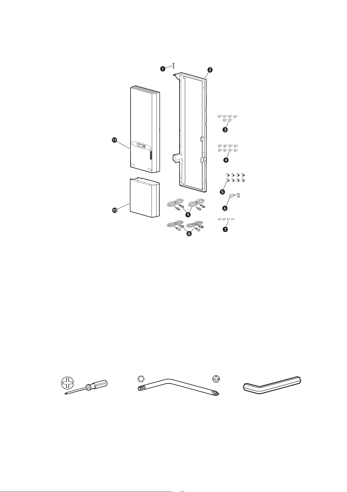
Inventory
na1511a
Item Description Quantity
Hinge pin 1
1
Fan assembly mounting frame
2
NOTE: Narrow frame shown; your frame may differ.
NetShelter SX M6 Phillips rack-mounting screws 6
3
NetShelter VX M6 Phillips rack-mounting screws 8
4
5 Hole plugs 8
6 M6 shoulder hex screw with lock washer 1
7 Fan assembly extension M4 Phillips mounting screws 4
8 Power cords—NEMA 5-15 2
9 Power cords—CEE22 2
: Fan assembly extension 1
; Fan assembly 1
1
Tools required (not provided)
#2 Phillips screwdriver M5 Torx®/Phillips Hex wrench
Receiving inspection
Inspect the package and contents for shipping damage, and make sure that all parts were sent. Report any
damage immediately to the shipping agent. Report missing contents, damage, or other problems
immediately to APC or your APC reseller.
3Rack Air Removal Unit
Page 10
Installation
ns0617a
Attach the Mounting Frame
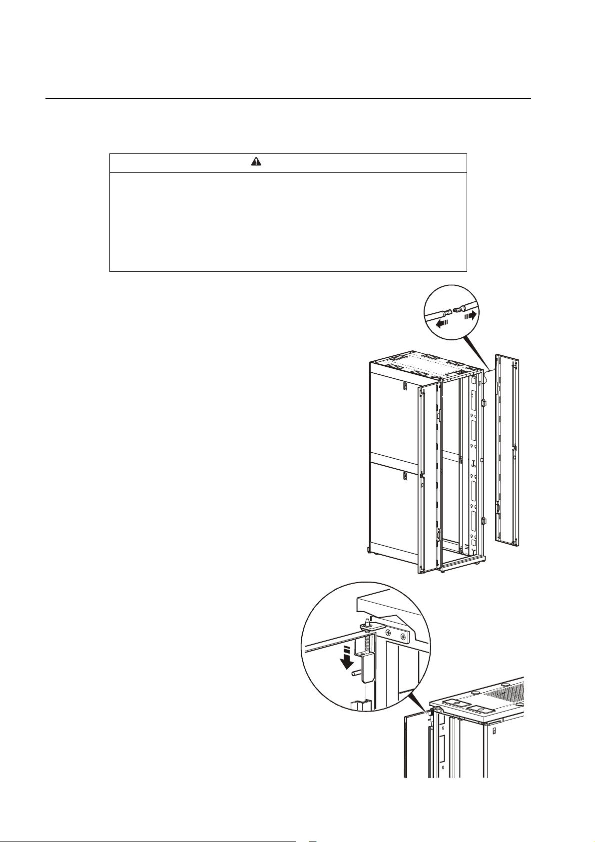
Remove the doors
WARNING
TIPPING OR DAMAGE HAZARD
• To avoid personal injury or damage to the enclosure, one person should support
the door while another person removes it from the frame.
• If the enclosure is not joined to other enclosures, ensure it contains sufficient
weight or has adequate support to prevent it tipping during ARU installation.
Failure to follow these instructions can result in serious injury, or
equipment damage.
1. If necessary, move the enclosure to allow at least 762 mm
(30 in) of clearance at the rear of the enclosure to install
the ARU.
2. Disconnect the grounding wires from each door.
3. Remove the grounding wires from the rack to enable the
ARU to fit properly.
4. Remove the rear doors from the enclosure.
Removing doors from an SX enclosure. Open the door 90
degrees and lift it up and off its hinges.
Removing doors from a VX enclosure.
1. Open the rear doors and pull down on the
spring-loaded hinge pin. Lift the doors
from their frame.
ns026 6a
Rack Air Removal Unit4
Page 11

2. Using an Allen wrench, remove the door
ns026 7a
ns0595a
bumpers at the top and bottom of the door
frame.
3. Using a Phillips head screwdriver, remove the
rear door hinges and the rear skirt from the
enclosure.
5Rack Air Removal Unit
Page 12

Secure the mounting frame to the enclosure
na
Note: On NetShelter SX
enclosures, the mounting
frame uses the door hinges
for correct installation.
na152 0a
A/B
B
A
All NetShelter SX 42U high enclosures
Note: Your mounting frame may look
slightly different.
WARNING
TIPPING OR DAMAGE HAZARD
Install the Rack Air Removal Unit SX only on an enclosure that is loaded with
equipment, counter-weighted, or stabilized to avoid tipping the enclosure.
Failure to follow these instructions can result in serious injury, or
equipment damage.
Attach the mounting frame to a 42U SX enclosure.
1. Remove the six hole plugs from the
mounting holes of the enclosure.
2. Lift and place the mounting frame on
top of the door hinges, letting the
frame rest on the hinges.
1518a
3. Secure the frame to the enclosure using six M6 Phillips
screws.
a. Use the top holes marked A/B.
b. Use the middle and bottom holes marked A.
c. If desired, fill unused middle holes marked B with
hole plugs (provided).
A
Rack Air Removal Unit6
Page 13

Attach the mounting frame to a 42U VX enclosure.
na152 6a
na1527a
A/B
A
B
A
All NetShelter VX 42U high enclosures
Note: Your mounting frame may look slightly
different.
1. Place the mounting frame on the enclosure, aligning
the top of the mounting frame with the top edge of
the enclosure opening.
2. Secure the mounting frame to the enclosure using eight
M6 Phillips screws (four per side). Use the holes marked C
on the inside edges of the mounting frame.
3. If desired, fill unused holes marked A/B, A, and B on the
front surface with hole plugs (provided).
C
C
C
C
7Rack Air Removal Unit
Page 14

Extend and attach the mounting frame
na1521a
Note: There are four holes on each side of the
expandable section of the frame. A 47U frame will use
the second and fourth holes for installation. A 48U frame
will use the first and third holes for installation.
na1529a
na1520a
A/B
B
If your enclosure is 47U or 48U tall, extend the mounting frame to accommodate the additional
U-spaces.
1. Remove the two screws on each side of the lower part of the
frame.
2. Extend the frame to the height of the enclosure.
3. Use the two screws removed in step 1 to attach the frame.
4. Place the mounting frame onto the enclosure.
5. For a NetShelter SX installation, secure the mounting frame to the
enclosure using six M6 Phillips screws (three per side). Use the
holes marked A/B and B on the front surface of the mounting
frame. For a NetShelter VX installation, secure the mounting
frame to the enclosure using eight M6 Phillips screws (four per
side). Use the holes marked D on the inside edges of the mounting
frame
6. If desired, fill unused mounting holes on the mounting frame
surface with hole plugs (provided).
na1522a
Note: Your mounting frame may look slightly different.
D
D
D
D
B
Rack Air Removal Unit8
Page 15

Install the fan assembly
na1530a
na1531a
1. Ensure that the leveling feet of the enclosure have
been lowered to the surface of the floor.
2. Using two people, lift the fan assembly using the
handles on the front, bottom, and inside of the unit.
3. Align the lower hinge pin of the mounting frame
with the hole in the pin on the fan assembly, and
carefully set it into place.
4.Align the upper hinge of the mounting frame with the upper
hinge of the fan assembly, and slide the hinge pin into position.
9Rack Air Removal Unit
Page 16

Install the anti-tip strap
na1605a
na1604 a
The anti-tip strap prevents the enclosure from tipping to the
side before the enclosure is stabilized.
Using the M6 shoulder hex screw and lock washer (provided),
attach the anti-tip strap.
CAUTION
TIPPING HAZARD
Do not remove the anti-tip strap after it has been installed. Lowering the leveling feet
of the enclosure will help stabilize it, but will not prevent it from tipping over.
Failure to follow these instructions can result in equipment damage.
Connect the ground wire
To ground the unit, attach the ground wire connected to the fan
assembly to the ground wire connected to the mounting frame.
Rack Air Removal Unit10
Page 17

Fan Assembly Extension
na1535a
Adjust the fan assembly extension
Install the fan assembly extension below the ARU on the mounting
frame to cover the open area. The extension is configured by
default for use in 42U enclosures. You can extend it to
accommodate a 47U or 48U enclosure.
1. Remove the four adjustment screws.
2. Slide the base down and align it with either the 47U or
48U assembly holes.
3. Reinstall the previously removed screws.
na15 34a
11Rack Air Removal Unit
Page 18

Attach the fan assembly extension
na1533b
1. Slide the fan assembly extension up and into the bottom
of the fan assembly.
2. Secure the fan assembly extension to the fan assembly
using four M4 Phillips machine screws.
3. Insert hole plugs into all open holes.
DAMAGE HAZARD
Do not overtighten the screws.
CAUTION
Failure to follow these instructions can result in equipment damage.
Rack Air Removal Unit12
Page 19

Connect the Power Supply
na1537 a
1. Ensure that there is adequate power for the fans to run at full capacity.
Acceptable Power
Voltage Frequency (Hz) Current (Amps)
120 60 12 (maximum)
100 60 12 (maximum)
200/208/230/240 50/60 10 (maximum)
The UPS in the enclosure must be sized properly to provide adequate power to this unit.
WARNING
DAMAGE HAZARD
If you are using a UPS, connect the Rack Air Removal Unit SX to a 3000VA,
2.7kW or higher Smart-UPS®. The UPS should not be loaded above 80% when
using the Rack Air Removal Unit SX.
Failure to follow these instructions can result in serious injury, or equipment
damage.
2. Using one of the supplied power cords, connect the female end to the A input socket on the inside
of the ARU, as shown. Plug the male end into a power-protected socket and tilt the retainer clip
up to ensure that it captures the socket and forms a secure connection.
3. To provide redundant power to the unit, use the B input socket to connect the ARU to a second
source of protected power.
13Rack Air Removal Unit
Page 20

Optional Items
na03
APC offers additional products (not included) for the Rack Air Removal Unit SX:
• Air Duct Kit (ACF126 for 24-inch ceiling tiles, ACF127 for 600-mm
ceiling tiles)—for removal of heat from the air conditioned room. This
product is required in a room with a ceiling less than 3.66 m (12 ft) high,
but is recommended for all installations regardless of ceiling height.
For more information on the Air Duct Kit see the installation sheet provided with the
Air Duct Kit (APC part number 990-2773), or on the APC Web site, www.apc.com.
• Temperature Sensor (AP9335T)—monitors the air
temperature at a location remote from the ARU.
For more information on temperature sensors,
see the installation sheet provided with the sensors (APC part number 990-2311), or on
the APC Web site, www.apc.com.
67a
• Alarm Beacon (AP9324)—will light up when an alarm is present.
Rack Air Removal Unit14
Page 21

Operation
?
Check
Log
Tem p.
Override
Alarm
Display Interface
You can use the display interface to configure settings, set alarm thresholds, and provide audible and
visual alarms.
Running
ESC
na1603a
1 Alarm When red, at least one new critical or warning alarm or event has occurred.
2 Temp Override When yellow, the temperature override alarm is active.
3 Check Log When yellow, at least one new event has been added to the event log.
4 Running When green, the ARU is operating.
5 Liquid crystal display (LCD) View alarms, status data, configuration items, and help files.
6
Up and down navigation keys Select menu items and access information.
7
ESC key Return to previous screen displayed.
8
HELP key Launch context-sensitive help. Press the HELP key for information about
each item on the screen and for instructions on how to perform certain tasks.
9
ENTER key Open menu items and input changes to system parameters.
15Rack Air Removal Unit
Page 22

Navigating the interface
Time: 13:15:23
na0158a
Time: 13:15:23
Time: 13:15:23
na0254a
Enter Password:
APC ****
Selector arrows. Press the up or down arrow key to move the selector arrow
setting. Press the
Continue arrows. Continue arrows
ENTER key to view the selected screen or modify the setting.
Date: 18-Jun-2007
indicate that additional options or settings are available on a
2
to a menu option or
1
menu or status screen. Press the up or down arrow key to view the additional items.
Date: 18-Jun-2007
na0281 a
Input arrows. Input arrows
pressing the up or down arrow key. Press the
next to a selected setting indicate that the setting can be modified by
3
ENTER key to save the change or the ESC key to cancel the
change.
Date: 18-Jun-2007
Password entry
When you attempt to change any of the settings, the display will prompt you to enter your password.
To enter your password, use the up or
alphabet. When you reach the desired letter, press the
down arrow keys to scroll through the
ENTER key and the
cursor will move to the next letter position. After entering the last letter of
your password, press the
ENTER key once more to submit your password.
Note: Passwords are case sensitive. See “Local Password” on page 21 to change your
password.
Rack Air Removal Unit16
Page 23

Set Points
Mode: Blade Serv ers
Total Flow: xxxcf m
kW Support: xx.x kW
na2278a
Master Control
Master Control:On/Std
To start the fans, select the On/Std (Standby) option on the menu and
change the setting to On. The fans will run according to the current
settings. Standby (Std) turns the fans off.
Mode
To use the predefined settings, select the rack configuration that is similar to your rack environment. If
you adjust the settings and the temperature override settings do not match the predefined settings, the
ARU displays Customized as your mode of operation.
Mode Flow Rate Airflow Ratio
Stand ard IT 7.5 kW (1200 CFM) 160 CFM per kW On 40°C (104°F)
Mixed IT 10 kW (1200 CFM) 120 CFM per kW On 45°C (113°F)
Blade Server 16.5 kW (1600 CFM) 80 CFM per kW On 50°C (122°F)
Temperature
Override
Temperature
Setpoint
Airflow. ARU airflow is variable between 400 and 2000 cfm. The settings are in 100 cfm increments
between 400 and 1000 cfm, and in 200 cfm increments thereafter.
Temp Override. Temperature override allows the ARU to increase the airflow in the enclosure if the
exhaust temperature exceeds the temperature set point Te m p S et P oi nt .
Temp Set Point. When the exhaust temperature exceeds the set point, the ARU will automatically
increase airflow if the Temp Override is On.
Total Flow
The amount of air being exhausted through the ARU.
kW Support
This kW value can be used to help you to pick the appropriate flow rate based on power draw of the
equipment in the rack. The kW value is a calculated value based on the Tot al F lo w and the Operating
Mode since different types of equipment have different airflow requirements.
17Rack Air Removal Unit
Page 24

Fan Status
ARU Fan: 1of4
Status: On & Ok
Speed: xxxxrpm
Flow: xxxxcfm
Exhaust Temperature
Upper Plenum: xxxC
Lower Plenum: xxxC
Override: Warning
ARU Fan
Select a fan to view its status.
Status
Summary of the selected fan.
OK. The fan is functioning.
Failed Off. The fan has failed and needs to be replaced.
Cyclic Failure. The fan status has changed from OK to Failed Off several times. Review the event log
to determine the cause.
Speed
The speed of the fan in cfm (cubic feet per minute) or m³/hr (meters cubed per hour). See “Config” on
page 21 to change the units of measure.
Flow
The amount of air the selected fan is moving through the duct into the exhaust system.
Exhaust
Upper Plenum
Temperature of the exhaust removed by fans 1 and 2.
Lower Plenum
Temperature of the exhaust removed by fans 3 and 4.
Override
Warning. The ARU has increased airflow in the enclosure to a level higher than the base airflow. This
occurs when the temperature override is enabled and the exhaust temperature is over the Tem p Se t po int .
Critical. The ARU fans are functioning at their highest speed, and the exhaust temperature is increasing.
Rack Air Removal Unit18
Page 25

Environment
Remote Sensor: 1 of 3
Temperature: xxxC
Status: Normal
Sensor Config.
Fan History
Fan Runtime
Alarm:>
50,000 hrs
Remote Sensor
Select the remote temperature sensor to view.
Temperature
Display the temperature of the selected sensor.
Status
View the detailed alarm status of the selected sensor.
Sensor Config.
View and configure the name, alarm limits, and location for the selected sensor.
Remote Sensor. Select a sensor using the arrow keys.
Name/Location. View and configure the name and location of a sensor.
Temperature Limits. View and configure the alarm limits of a sensor. Set the Low/Hi warning
threshold, the Min/Max critical thresholds, and the Alarm Reset Hysteresis. The hysteresis setting
requires the measurement causing an alarm to correct itself by at least the set amount before the alarm
condition will end.
Rate of Change. View and configure the rate of change alarm settings.
Maintenance
Fan History
ARU Fan. View the history of a fan.
Date. View the date the fan was put into service.
Runhours. View the number of hours the fan has been running.
Remaining. View the number of hours remaining before a runtime alarm will exist.
Fan Runtime
Fan Runtime Alarm. Set the number of hours the fan operates before an alarm condition indicates that
the fan needs to be replaced.
Page 26

Alarms
View Active Alarms
Alarm/Event Log
Alarm Beacon
Alarm Beeper: ON
When an alarm is triggered, the display interface can issue alerts by the following methods:
• Active alarm screen entry on scrolling status screens
• An optional audible alarm, if enabled, every 30 seconds
• An optional alarm beacon
View Active Alarms
The View Alarms screen provides the number of alarms, the
severity level of each active alarm, and a brief description of each
alarm. Press the up or down arrow keys to view the entire list if it
consists of more than one screen.
Alarm/Event Log
View a list of past alarms and events.
New Logged Items. View items logged since the New Logged Items list was last viewed.
Entire Log. View the entire alarm/event log.
Clear Log. A confirmation screen displays when this option is selected. Enter the Admin password to
clear the alarm list. Select YES to clear all of the alarms in the list. Select NO to return to the main
screen. If the conditions that caused the alarm still exist, those conditions will cause the alarm to be
regenerated.
Clr Latched Alarms. Clear the latched alarm log.
Alarms cleared:
Press any key to Continue.
Note: Clearing the log will remove information from the Web and Telnet views as well.
Alarm Beacon
Status. View the status of an installed alarm beacon (optional).
Control. Turn the alarm beacon on or off.
Alarm Beacon Map. Use the arrow keys to scroll through the list of conditions. Press Enter to map a
condition to the beacon. When Apply Now (Pending) appears on the screen, press Enter to save the
changes.
Alarm Beeper
Turn the alarm beeper on or off. When the alarm beeper is set to ON, the alarm beeps when an alarm
condition exists. When the alarm beeper is set to OFF, the alarm does not beep at all. When an alarm
condition exists, pressing any button stops the alarm beeper. The alarm beeper restarts if another alarm
condition exists.
Rack Air Removal Unit20
Page 27

Config
Device/Network
Units/Log Lamp/Etc
Manufacturer Data
Factory Defaults
Device ID
Password: **********
Timeout: 10 Min
Invalidate NOW
Device/Network
Local Password. Change the
system password or the amount of
time before timeout.
Password time-out. Set the length of time which can elapse when no keys are pressed before the
display interface returns to the scrolling screen status. The password must then be entered to regain
access.
Invalidate Password. Override the password time-out and
require password entry again.
Date/Time. View or change the current date and time.
Local Interface. Change preferences for contrast, key clicks,
beeper, and volume.
Network Config. View or change the IP address, subnet mask, default gateway, or Boot Mode.
• IP: The IP address of the Network Management Card.
• SM: The subnet mask for the Network Management Card.
• GW: The default gateway for the Network Management Card.
• Boot Mode: The method by which the Network Management Card acquires network settings.
– Manual: In manual mode you must enter the IP address, subnet mask, and default gateway
using the IP Address menu.
– BOOTP: Set the Network Management Card to obtain its network settings from a BOOTP
server.
– DHCP: Set the Network Management Card to obtain its network settings from DHCP server
– BOOTP&DHCP: Set the Network Management Card to search for its network settings from
either a BOOTP or a DHCP server.
Units/Log Lamp/Etc
Flow Units. Select cfm (cubic feet per minute) or m³/hr (meters cubed per hour).
Temp Units. Select C (Celsius) or F (Fahrenheit).
Check Log.
None/Disabled The light on the user interface will not light when a new event is added to the
event log.
Informational The light will be illuminated when any event is logged.
Warning The light will be illuminated when a warning or critical alarm is logged.
Severe/Critical The light will be illuminated only when a critical event is logged.
Rem. Sensor Display.
temperature of the enclosure. Select Hide if a sensor is not installed.
Select Show to display a summary of the sensor measuring the inlet
21Rack Air Removal Unit
Page 28

Manufacturer Data
AC Input A: On
AC Input B: Off
Redundant Pwr: On
Mfg Data. Displays device name and factory data.
Factory Defaults
Set Configuration to Factory Defaults? Select YES to return all settings to the factory default
settings, or select NO, ABORT.
Device ID
Name. Define a name for the unit (40 characters maximum).
Contact. Define a contact person for the unit (40 characters maximum).
Location. Define the location of the unit (40 characters maximum).
Input
AC Input A
Indicates whether the AC voltage on this input is sufficient to
operate the ARU.
AC Input B
Indicates whether the AC voltage on this input is sufficient to
operate the ARU.
Redundant Pwr
Set to ON to enable an alarm for loss of redundant power. Set to OFF when using only one input line
cord.
Rack Air Removal Unit22
Page 29

Troubleshooting
Problem Possible Cause Corrective Action
The ARU is operating on
alternate power source (Input
B) even though the main power
source (Input A) is available.
The ARU is delivering less
CFM than the set value.
The unit is not reading the
proper exhaust temperature.
The beacon is not working. Improper connection of the
The network port is not
working.
The display interface is not
functioning properly.
The voltage of Input A may be less
than 90 V.
The power board may be faulty. Contact APC Customer Support to replace the
The power board may be faulty. Contact APC Customer Support to replace the
One or more fans may be faulty. Contact APC Customer Support to replace the
One or more fans may be faulty. Contact APC Customer Support to replace the
Sensor may be faulty. Contact APC Customer Support to replace the
beacon.
The power board may be faulty. Contact APC Customer Support to replace the
Beacon may be faulty. Replace the beacon (AP9324).
The network cable may not be
properly connected.
The Network Management Card
may be faulty.
The Network Management Card
may be faulty.
Backlight of display interface may
be faulty.
Check the Input A voltage. If it is less than 90 V,
increase the voltage to 90 V or greater.
electronic module (WOM-7053).
electronic module (W0M-7053).
faulty fan module (W0M-7054).
faulty fan module (W0M-7054).
faulty sensor.
Make sure that beacon is properly connected.
electronic module (W0M-7053).
Properly connect the network cable.
Contact APC Customer Support to replace the
electronic module (W0M-7053).
Contact APC Customer Support to replace the
electronic module (W0M-7053).
Contact APC Customer Support to replace the
display interface.
The console port is not
working.
The remote sensor is not
reading proper temperature.
The unit may be improperly
connected to the console port.
The Network Management Card
may be faulty.
The controller board may be
faulty.
The sensor may be faulty. Contact APC Customer Support to replace the
The remote sensor may be
improperly connected, or
connected to the wrong port.
Make sure the cable is properly connected.
Contact APC Customer Support to replace the
electronic module (W0M-7053).
Contact APC Customer Support to replace the
electronic module (W0M-7053).
sensor.
Ensure the cable is properly plugged into the
ARU and the sensor.
23Rack Air Removal Unit
Page 30

Specifications
Electrical
Input voltage 100 V–240 V, 1 Phase
Frequency 50/60 Hz
Rated current 12 A–10 A
Maximum power consumption 1200 Watts
Environmental
Maximum inlet temperature . . . . . . . . . . . . . . . . . . . . . . . . . . . 50ºC (122ºF)
Maximum airflow (with ducting kit installed) . . . . . . . . . . . . . 2000 CFM (3400 m3/hr)
Sound level at maximum airflow . . . . . . . . . . . . . . . . . . . . . . . 79 dBA at 1 m (3.3 ft)
Physical Dimensions
Fan Assembly
Fan assembly
(H x W x D). . . . . . . . . . . . . . . . . . . . . . . . . . . . . . . . . . . . . . . .
Shipping dimensions
(H x W x D) . . . . . . . . . . . . . . . . . . . . . . . . . . . . . . . . . . . . . . .
Net weight . . . . . . . . . . . . . . . . . . . . . . . . . . . . . . . . . . . . . . . . . 47 kg (104 lb)
Shipping weight. . . . . . . . . . . . . . . . . . . . . . . . . . . . . . . . . . . . . 60 kg (125 lb)
Fan Assembly Mounting Frame & Extension
Fan assembly mounting frame (H x W x D) . . . . . . . . . . . . . . . 191.8 x 60 x 22.9 cm
Fan assembly mounting frame extension (H x W x D) . . . . . . . 55.9 x 58.4 x 15.9 cm
Shipping dimensions—frame and extension (H x W x D) . . . . 208.3 x 78.7 x 38.0 cm
Net weight—frame . . . . . . . . . . . . . . . . . . . . . . . . . . . . . . . . . . 12 kg (25 lb)
Net weight—extension . . . . . . . . . . . . . . . . . . . . . . . . . . . . . . . 9 kg (19 lb)
Shipping weight—frame and extension . . . . . . . . . . . . . . . . . . 33 kg (73 lb)
135.3 x 58.4 x 19.0 cm
(53.3 x 23 x 7.5 in)
152.4 x 81.3 x 30.5 cm
(60 x 32 x 12 in)
(75.5 x 23.5x 9 in)
(22 x 23 x 6.3 in)
(82 x 31 x 15 in )
Compliance
UL, C-UL, VDE, FCC Part 15, CE, VCCI, CISPR 22, CISPR 24, EN 61000-3-2, EN 61000-3-3, AS/NZS
CISPR 22, IRAM
Heat Removal Capacity
Server Inlet Temperature °F (°C ) Temperature Rise °F (°C ) Heat Removed (kW)
77 (25.0) 27 (15.0) 17
75 (23.9) 29 (16.1) 18
72 (22.2) 32 (17.8) 20
70 (21.1) 34 (18.9) 21
68 (20.0) 36 (20.0) 23
* Capacity at maximum airflow rate with the stated temperature rise across the rack. Other airflows and
temperature differentials will result in different heat removal capacities
Estimated power that can be drawn by the enclosure based on
the amount of airflow provided by the ARU
Rack Air Removal Unit24
Page 31

Page 32

APC Worldwide Customer Support
Customer support for this or any other APC product is available at no charge in any of the following ways:
• Visit the APC Web site to access documents in the APC Knowledge Base and to submit customer
support requests.
– www.apc.com (Corporate Headquarters)
Connect to localized APC Web sites for specific countries, each of which provides customer support
information.
– www.apc.com/support/
Global support searching APC Knowledge Base and using e-support.
• Contact the
– Local, country-specific centers: go to www.apc.com/support/contact for contact information.
For information on how to obtain local customer support, contact the APC representative or other distributors
from whom you purchased your APC product.
APC Customer Support Center by telephone or e-mail.
© 2011 APC by Schneider Electric. APC, and the APC logo are owned by Schneider Electric Industries
S.A.S., American Power Conversion Corporation, or their affiliated companies. All other trademarks are
property of their respective owners.
990-1232H-001
8/2011
 Loading...