

Page 1
Micrologic™ 2.0A, 3.0A, 5.0A, and 6.0A Electronic Trip
Units
Unidades de disparo electrónico Micrologic™ 2.0A, 3.0A,
5.0A y 6.0A
MC
Déclencheurs électroniques Micrologic
2.0A, 3.0A, 5.0A et
6.0A
Instruction Bulletin
Boletín de instrucciones
Directives d'utilisation
48049-136-05
Rev. 01, 04/2012
Retain for Future Use. /
Conservar para uso futuro. /
À conserver pour usage ultérieur.
Page 2

Page 3
Micrologic™ 2.0A, 3.0A, 5.0A, and 6.0A
Electronic Trip Units
Instruction Bulletin
48049-136-05
Rev. 01, 07/2012
Retain for future use.
ENGLISH
Page 4
Micrologic™ 2.0A, 3.0A, 5.0A, and 6.0A Electronic Trip Units 48049-136-05
DANGER
WARNING
E
IEC
ANSI
Rev. 01, 07/2012
Hazard Categories and Special
ENGLISH
Symbols
Read these instructions carefully and look at the equipment to become
familiar with the device before trying to install, operate, service or maintain
it. The following special messages may appear throughout this bulletin or on
the equipment to warn of potential hazards or to call attention to information
that clarifies or simplifies a procedure.
The addition of either symbol to a “Danger” or “Warning” safety label
indicates that an electrical hazard exists which will result in personal injury if
the instructions are not followed.
This is the safety alert symbol. It is used to alert you to potential personal
injury hazards. Obey all safety messages that follow this symbol to avoid
possible injury or death.
DANGER indicates a hazardous situation which, if not avoided, will result
in death or serious injury.
WARNING indicates a hazardous situation which, if not avoided, can
result in death or serious injury.
CAUTION
CAUTION indicates a hazardous situation which, if not avoided, can
result in minor or moderate injury.
NOTIC
NOTICE is used to address practices not related to physical injury. The
safety alert symbol is not used with this signal word.
NOTE: Provides additional information to clarify or simplify a procedure.
Please Note Electrical equipment should be installed, operated, serviced, and
maintained only by qualified personnel. No responsibility is assumed by
Schneider Electric for any consequences arising out of the use of this
material.
FCC Notice This equipment has been tested and found to comply with the limits for a
Class A digital device, pursuant to part 15 of the FCC Rules. These limits
are designed to provide reasonable protection against harmful interference
when the equipment is operated in a commercial environment. This
equipment generates, uses, and can radiate radio frequency energy and, if
not installed and used in accordance with the instruction manual, may cause
harmful interference to radio communications. Operation of this equipment
in a residential area is likely to cause harmful interference in which case the
user will be required to correct the interference at his own expense. This
Class A digital apparatus complies with Canadian ICES-003.
© 1999–2012 Schneider Electric All Rights Reserved2-EN
Page 5

48049-136-05 Micrologic® 2.0A, 3.0A, 5.0A and 6.0A Electronic Trip Units
Rev. 01, 07/2012 Table of Contents
Table of Contents
SECTION 1: GENERAL INFORMATION ...................................................................................................................... 5
Introduction ................................................................................................. 5
Communications ......................................................................................... 5
Trip Unit Settings ........................................................................................ 5
Micrologic 2.0A Trip Unit ....................................................................... 6
Micrologic 3.0A Trip Unit ....................................................................... 6
Micrologic 5.0A Trip Unit ....................................................................... 7
Micrologic 6.0A Trip Unit ....................................................................... 8
Zone-Selective Interlocking ......................................................................... 9
Trip Unit Switches ..................................................................................... 10
Long-Time Protection .......................................................................... 10
Short-Time Protection ......................................................................... 11
Instantaneous Protection ..................................................................... 12
Ground-Fault Protection ...................................................................... 13
Indicator Lights .......................................................................................... 13
Overload Indicator Light ...................................................................... 13
Trip Indicator Lights ............................................................................. 14
Ammeter ................................................................................................... 14
Trip Unit Testing ........................................................................................ 14
Micrologic Trip Unit Configuration ............................................................. 14
Control Power ...................................................................................... 14
External Power Supply ........................................................................ 15
ENGLISH
SECTION 2: AMMETER .................................................................................................................... 16
Display ...................................................................................................... 16
Ammeter Measurements ........................................................................... 16
Accessing Information ............................................................................... 16
Current Menu ...................................................................................... 17
Peak Menu .......................................................................................... 18
Switch Settings Menu .......................................................................... 19
SECTION 3: OPERATION .................................................................................................................... 20
Switch Setting Adjustment ........................................................................ 20
Examples .................................................................................................. 20
Micrologic 2.0A Trip Unit ..................................................................... 20
Micrologic 3.0A Trip Unit ..................................................................... 21
Micrologic 5.0A Trip Unit ..................................................................... 21
Micrologic 6.0A Trip Unit ..................................................................... 22
Zone-Selective Interlocking (ZSI) .............................................................. 23
Communication Module values ................................................................. 24
Trip Unit Settings Check ........................................................................... 26
Trip Unit Operation Verification ................................................................. 26
Equipment Ground-Fault Trip Functions Testing ...................................... 27
Trip Unit Resetting .................................................................................... 27
Trip Unit Status Check .............................................................................. 27
SECTION 4: TRIP UNIT REPLACEMENT .................................................................................................................... 28
Required Tools .......................................................................................... 28
Preparation ............................................................................................... 28
Record Switch Settings ....................................................................... 28
Circuit Breaker Disconnection ............................................................. 28
Circuit Breaker Accessory Cover Removal ......................................... 28
Rating Plug Removal ........................................................................... 29
Trip Unit Removal ................................................................................ 29
© 1999–2012 Schneider Electric All Rights Reserved 3-EN
Page 6

Micrologic™ 2.0A, 3.0A, 5.0A, and 6.0A Electronic Trip Units 48049-136-05
Table of Contents Rev. 01, 07/2012
ENGLISH
SECTION 5: ADJUSTABLE RATING PLUG REPLACEMENT .............................................................................................. 33
SECTION 6: BATTERY REPLACEMENT ....................................................................................................................34
Trip Unit Replacement ..............................................................................29
Battery Installation ...............................................................................29
Trip Unit Installation .............................................................................30
Circuit Breaker Accessory Cover Replacement ........................................ 31
Trip Unit Installation Check .......................................................................32
Secondary Injection Testing ................................................................32
Primary Injection Testing ..................................................................... 32
Check Accessory Operation ................................................................ 32
Trip Unit Setup ..........................................................................................32
Circuit Breaker Reconnection ...................................................................32
Rating Plug Removal ................................................................................ 33
New Rating Plug Installation ..................................................................... 33
Circuit Breaker Disconnection ...................................................................34
Circuit Breaker Accessory Cover Removal ...............................................34
Withstand Module Shifting ........................................................................34
Battery Replacement .................................................................................34
Withstand Module Replacement ............................................................... 35
Circuit Breaker Accessory Cover Replacement ........................................ 35
Circuit Breaker Reconnection ...................................................................35
APPENDIX A: REGISTER LIST ....................................................................................................................36
List of Registers ........................................................................................36
© 1999–2012 Schneider Electric All Rights Reserved4-EN
Page 7
48049-136-05 Micrologic™ 2.0A, 3.0A, 5.0A, and 6.0A Electronic Trip Units
06134858
A
B
D
E
C
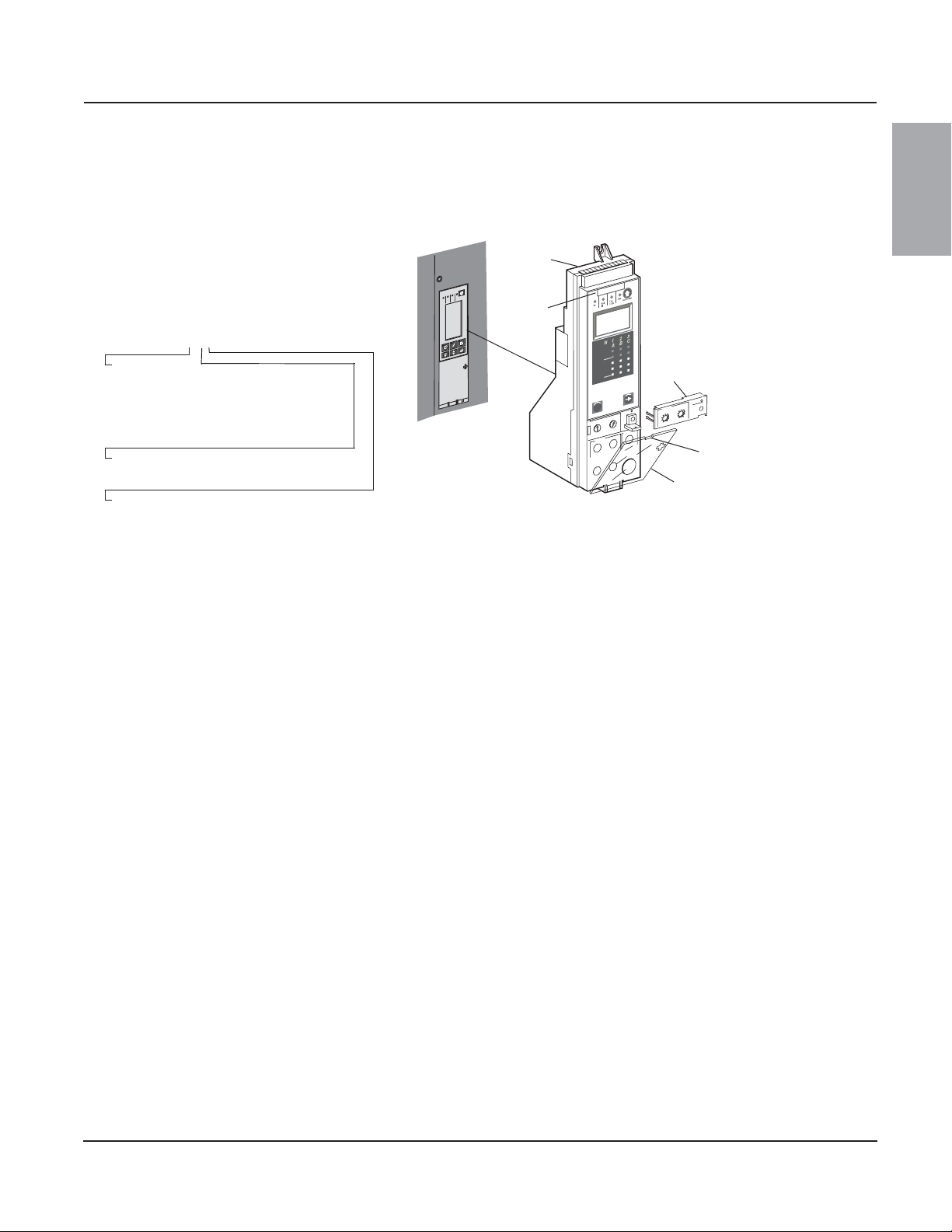
A—Micrologic Trip Unit
B—Product Name
C—Switch Cover
D—Switch Cover Opening Slot
E—Adjustable Rating Plug
Rev. 01, 07/2012 Section 1—General Information
Section 1—General Information
Introduction
Micrologic™ trip units (A) provide adjustable
tripping functions on electronic trip circuit
breakers. The product name (B) specifies the
level of protection provided by the trip unit.
Micrologic 3.0A
Type of protection
2—Basic IEC protection (LS0)
3—Basic UL protection (LI)
5—Selective protection (LSI)
6—Selective protection plus ground fault
protection for equipment (LSIG)
Trip unit series
0—Indicates the first version
Type of measurement
None—Provides protection only
A—Provides protection plus ammeter measurements
Micrologic trip units are field replaceable to allow
for upgrading of the trip unit in the field. For
complete information on available circuit breaker
models, frame sizes, interrupting ratings, sensor
plugs, rating plugs and trip units, see the product
catalog.
Figure 1: Micrologic Trip Unit
rolo
ic
M
06133249
%
0
0
1
%
0
4
u
n
e
m
ENGLISH
A
7.0
ic
g
m
ar
l
a
e
m
i
8
t
r
12
t
ng
o
l
)
4
6
s
(
1
8
.
r
9
I
.
2
20
7
.
5
9
.
1
24
6
8
.
9
.
5
.
r
I
6
@
5
.
1
n
.4
I
x
Communications Micrologic trip units can communicate with other devices if the optional
Circuit Breaker Communication Module (BCM) is installed. For information
on the communication module, see the product catalog and Modbus™
Communications System, Data Bulletin 0613IB1201.
Trip Unit Settings On the face of the trip unit are adjustable switches to allow changing of trip
characteristics. Trip units are shipped with the long-time pickup switch set at
1.0 and all other trip unit adjustments set at their lowest settings.
© 1999–2012 Schneider Electric All Rights Reserved
5-EN
Page 8
Micrologic™ 2.0A, 3.0A, 5.0A, and 6.0A Electronic Trip Units 48049-136-05
0 Ir Isd I
t
06134245
06134246
Micrologic 2.0 A
menu
long time
alarm
instantaneous
.4
.5
.6
.7.8.9
.95
.98
1
Ir
x In
.5
1
2
4
8
12
16
20
tr
(s)
@
6 Ir
24
setting
Isd
2.5
5
6
1.5
2
3
4
8
10
x Ir
G
F
A
H
J
I
F
G
H
K
B
C
E
D
N
M
L
06133243
Micrologic 3.0 A
menu
long time
alarm
instantaneous
.4
.5
.6
.7.8.9
.95
.98
1
Ir
x In
.5
1
2
4
8
12
16
20
tr
(s)
@
6 Ir
24
3
6
8
setting
Ii
1.5
2
4
5
10
12
x In
0 Ir Ii I
t
06133201
G
F
A
H
J
I
F
G
H
K
B
C
E
D
N
M
L
Section 1—General Information Rev. 01, 07/2012
ENGLISH
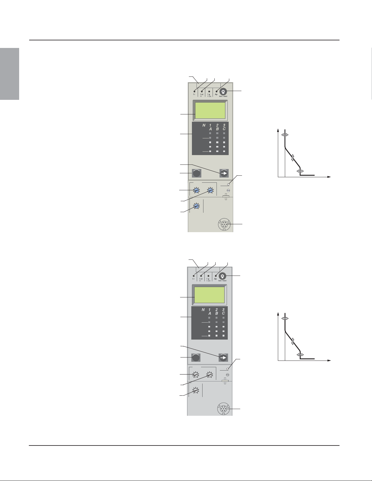
Micrologic 2.0A Trip Unit
The Micrologic 2.0A trip unit provides basic IEC
(LS0) protection and a built-in ammeter.
A. Trip unit name
B. Alphanumeric display
C. Three-phase bar graph
D. Scroll button
E. Menu button
F. Long-time pickup (Ir) switch
G. Long-time delay (tr) switch
H. Short-time pickup (Isd) switch*
I. Test plug receptacle
J. Overload indicator light
K. Reset button for battery status check and trip
L. Self-protection indicator light
M. Short-time or instantaneous trip indicator
N. Long-time trip indicator light
NOTE: For use with IEC circuit breakers only.
Figure 2: 2.0A Trip Unit
indicator LED
light
Micrologic 3.0A Trip Unit
The Micrologic 3.0A trip unit provides basic UL
(LI) protection and a built-in ammeter.
A. Trip unit name
B. Alphanumeric display
C. Three-phase bar graph
D. Scroll button
E. Menu button
F. Long-time pickup (Ir) switch
G. Long-time delay (tr) switch
H. Instantaneous pickup (Ii) switch
I. Test plug receptacle
J. Overload indicator light
K. Reset button for battery status check and trip
L. Self-protection indicator light
M. Short-time or instantaneous trip indicator
N. Long-time trip indicator light
*Short-time delay is factory set at 0 (no delay), thus short-time
pickup provides instantaneous protection.
indicator LED
light
Figure 3: 3.0A Trip Unit
© 1999–2012 Schneider Electric All Rights Reserved6-EN
Page 9
48049-136-05 Micrologic™ 2.0A, 3.0A, 5.0A, and 6.0A Electronic Trip Units
Micrologic 5.0 A
menu
d
elay
sh
o
r
t
ti
me
lon
g
ti
me
a
l
a
rm
tr
(s)
se
tting
.4
.5
.
6
.7
.8
.9
.9
5
.
9
8
1
Ir
x
In
.5
1
2
4
8
1
2
1
6
2
0
@
6 I
r
2
4
06133244
e
4
I i
x In
3
6
8
10
12
15
off
2
tsd
(s)
on I2t
.2
.3
.4
.4
.1
.2
.3
.1
0
off
x Ir
2
2.5
3
4
5
6
8
10
Isd
1.5
i
n
stantan
eo
u
s
G
F
A
H
L
K
F
G
J
M
B
C
E
D
P
O
N
I
J
I
H
Rev. 01, 07/2012 Section 1—General Information
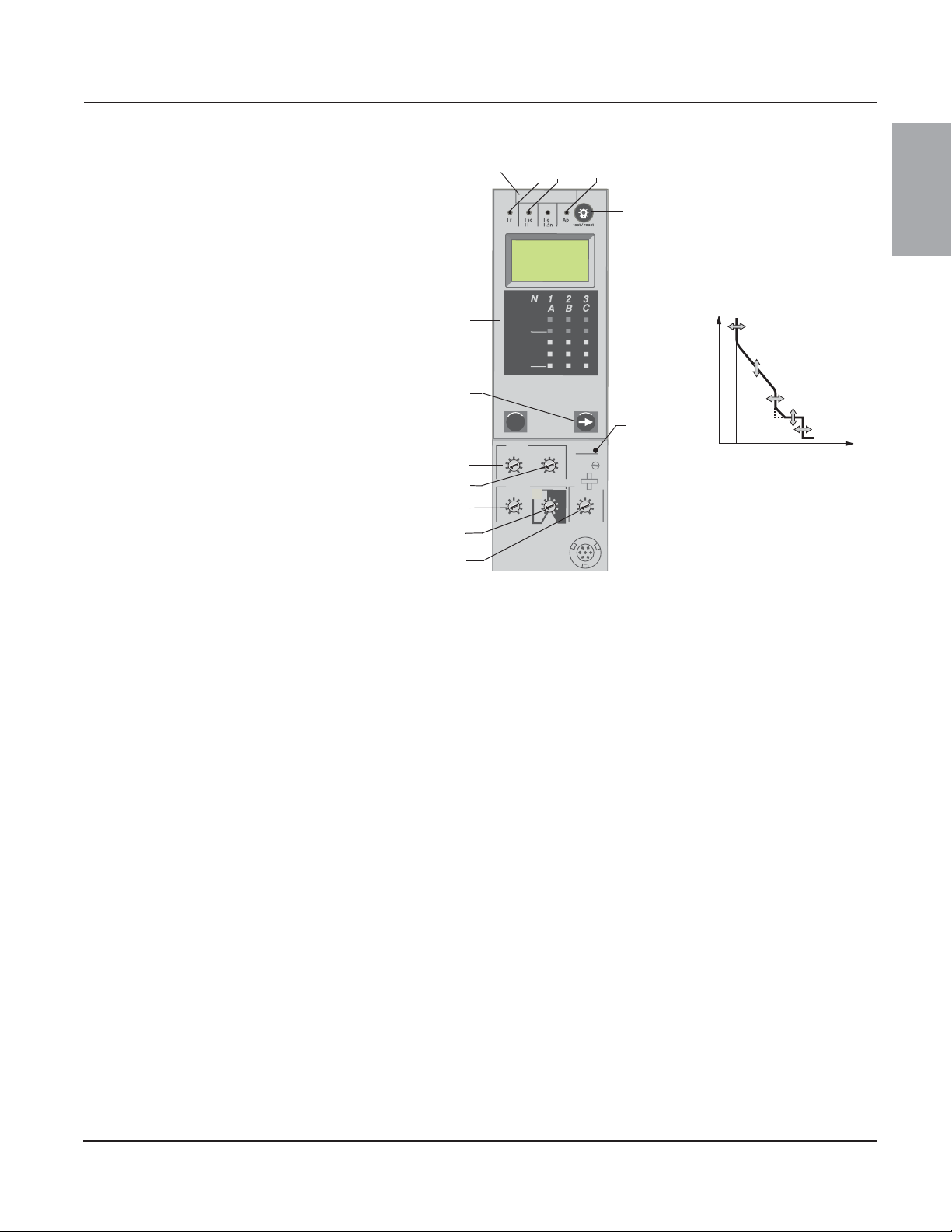
Micrologic 5.0A Trip Unit
The Micrologic 5.0A trip unit provides selective
(LSI) protection and a built-in ammeter.
A. Trip unit name
B. Alphanumeric display
C. Three-phase bar graph
D. Scroll button
E. Menu button
F. Long-time pickup (Ir) switch
G. Long-time delay (tr) switch
H. Short-time pickup (Isd) switch
I. Short-time delay (tsd) switch
J. Instantaneous pickup (Ii) switch
K. Test plug receptacle
L. Overload indicator light
M. Reset button for battery status check and trip
indicator LED
N. Self-protection indicator light
O. Short-time or instantaneous trip indicator
light
P. Long-time trip indicator light
Figure 4: 5.0A Trip Unit
t
06133202
0 Ir Isd I
Ii
ENGLISH
© 1999–2012 Schneider Electric All Rights Reserved
7-EN
Page 10
Micrologic™ 2.0A, 3.0A, 5.0A, and 6.0A Electronic Trip Units 48049-136-05
Micrologic 6.0 A
menu
delay
short tim
e
long time
alarm
ground fault
setting
test
.4
.5
.6
.7.8.9
.95
.98
1
Ir
x In
.5
1
2
4
8
12
16
20
tr
(s)
@
6 Ir
24
tsd
tg
06133245
4
I i
x In
3
5
6
10
12
15
off
2
tsd
(s)
on I2t
.2
.3
.4
.4
.1
.2
.3
.1
0
off
x Ir
2
2.5
3
4
5
6
8
10
Isd
1.5
on
I
2
t
.2
.3
.4
.4
.1
.2
.3
.1
0
off
B
C
D
E
F
G
H
J
Ig
A
(s)
instantaneous
40
100
%
%
0 Ir Isd I
t
Ii
06133202
0 I
t
I2t off
I2t on
Ig
06133247
G
F
A
H
O
M
F
G
J
P
B
C
E
D
T
S
Q
I
J
I
H
K
L
N
R
K
L
Section 1—General Information Rev. 01, 07/2012
ENGLISH
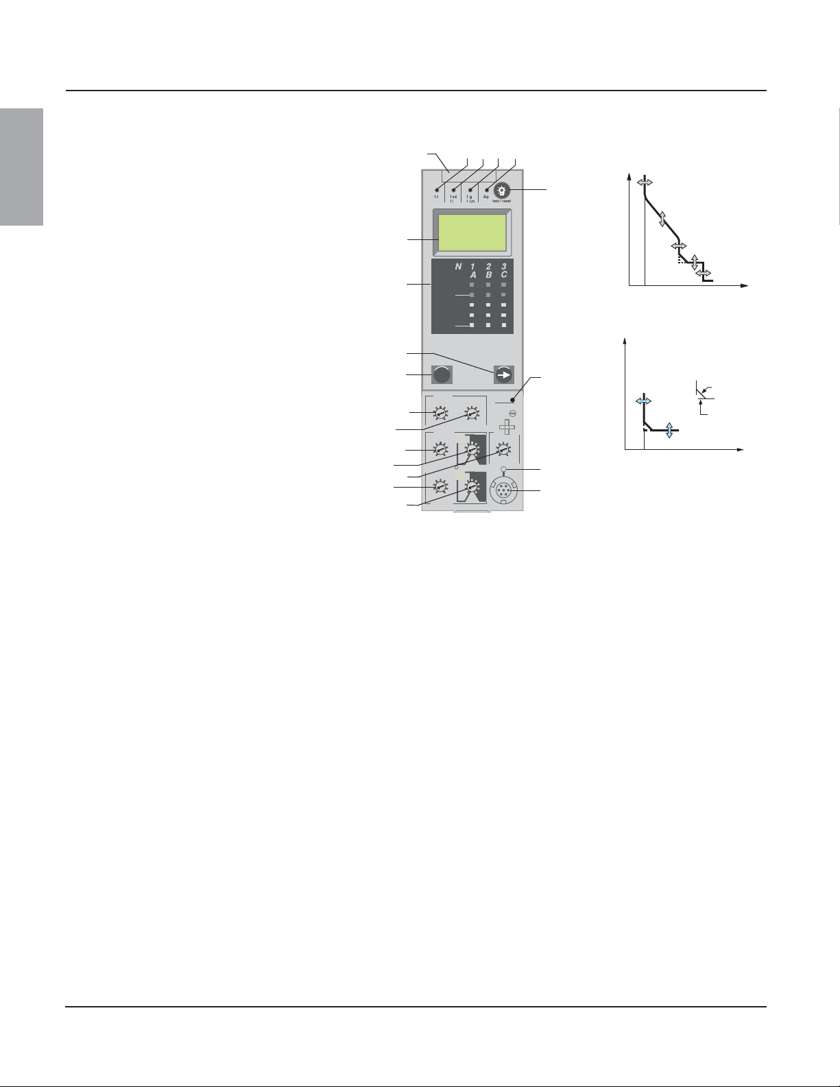
Micrologic 6.0A Trip Unit
The Micrologic 6.0A trip unit provides selective
and ground-fault protection for equipment
(d1200 A) (LSIG) and a built-in ammeter.
A. Trip unit name
B. Alphanumeric display
C. Three-phase bar graph
D. Scroll button
E. Menu button
F. Long-time pickup (Ir) switch
G. Long-time delay (tr) switch
H. Short-time pickup (Isd) switch
I. Short-time delay (tsd) switch
J. Instantaneous pickup (Ii) switch
K. Ground-fault pickup (Ig) switch
L. Ground-fault delay (tg) switch
M. Test plug receptacle
N. Ground fault push-to-trip button
O. Overload indicator light
P. Reset button for battery status check and trip
Q. Self-protection indicator light
R. Ground-fault trip indicator light
S. Short-time or instantaneous trip indicator
T. Long-time trip indicator light
Figure 5: 6.0A Trip Unit
indicator LED
light
© 1999–2012 Schneider Electric All Rights Reserved8-EN
Page 11

48049-136-05 Micrologic™ 2.0A, 3.0A, 5.0A, and 6.0A Electronic Trip Units
Rev. 01, 07/2012 Section 1—General Information
Zone-Selective Interlocking
Short-time and ground-fault protection can be
interlocked to provide zone-selective
interlocking.
Control wiring links several trip units in the
distribution network and in the event of a fault, a
trip unit will obey the set delay time only if
receiving a signal from a downstream trip unit.
If the trip unit does not receive a signal, tripping
will be instantaneous (with no intentional delay).
• The fault is cleared instantaneously by the
nearest upstream circuit breaker.
• Thermal stresses (I
2
t) in the network are
minimized without any effect on the correct
time delay coordination of the installation.
Figure 6 shows circuit breakers 1 and 2 zoneselective interlocked.
• A fault at A is seen by circuit breakers 1 and
2. Circuit breaker 2 trips instantaneously and
also informs circuit breaker 1 to obey set
delay times. Thus, circuit breaker 2 trips and
clears the fault. Circuit breaker 1 does not
trip.
• A fault at B is seen by circuit breaker 1.
Circuit breaker 1 trips instantaneously since
it did not receive a signal from the
downstream circuit breaker 2. Circuit breaker
1 trips and clears the fault. Circuit breaker 2
does not trip.
2
NOTE: Use I
t off with ZSI for proper coordination. Using I2t on with ZSI is
not recommended as the delay in the upstream device receiving a restraint
signal could result in the trip unit tripping in a time shorter than the published
trip curve.
NOTE: Setting short-time delay (tsd) or ground-fault delay (tg) to the 0
setting will eliminate selectivity for that circuit breaker.
Figure 6: Zone-Selective Interlocking
06133376
1
B
2
A
ENGLISH
© 1999–2012 Schneider Electric All Rights Reserved
9-EN
Page 12
Micrologic™ 2.0A, 3.0A, 5.0A, and 6.0A Electronic Trip Units 48049-136-05
x Ir
2
2.5
3
4
5
6
8
10
1.
5
setting
Isd
instantaneous
long time
alarm
tr
(s)
.4
.5
.6
.7.8.9
.95
.98
1
Ir
x In
.5
1
2
4
8
12
16
20
@ 6 Ir
24
06134243
x In
2
3
4
5
6
8
10
12
1.
5
setting
Ii
instantaneous
long time
alarm
tr
(s)
.4
.5
.6
.7.8.9
.95
.98
1
Ir
x In
.5
1
2
4
8
12
16
20
@ 6 Ir
24
06133203
.4
.5
.6
.7.8.9
.95
.98
1
delay
short tim
e
I itsd
(s)
on I2t
.2
.3
.4
.4
.1
.2
.3
.1
0
off
instantaneous
long time
alarm
Ir
x In
.5
1
2
4
8
12
16
20
tr
(s)
@
6 Ir
24
setting
x Ir
2
2.5
3
4
5
6
8
10
Isd
1.
5
x In
3
4
6
8
10
12
15
off
2
06133204
.4
.5
.6
.7.8.9
.95
.98
1
delay
short tim
e
I itsd
(s)
on I2t
.
2
.
3
.
4
.
4
.
1
.
2
.
3
.
1
0
off
instantaneous
long time
alarm
Ir
x In
ground fault
B
C
D
E
F
G
H
J
Ig tg
(s)
on I2t
.
2
.
3
.
4
.
4
.
1
.
2
.
3
.
1
0
off
A
.5
1
2
4
8
12
16
20
tr
(s)
@
6 Ir
24
setting
x Ir
2
2.5
3
4
5
6
8
10
Isd
1.
5
x In
3
4
5
8
10
12
15
off
2
test
06133351
Section 1—General Information Rev. 01, 07/2012
Trip Unit Switches
ENGLISH
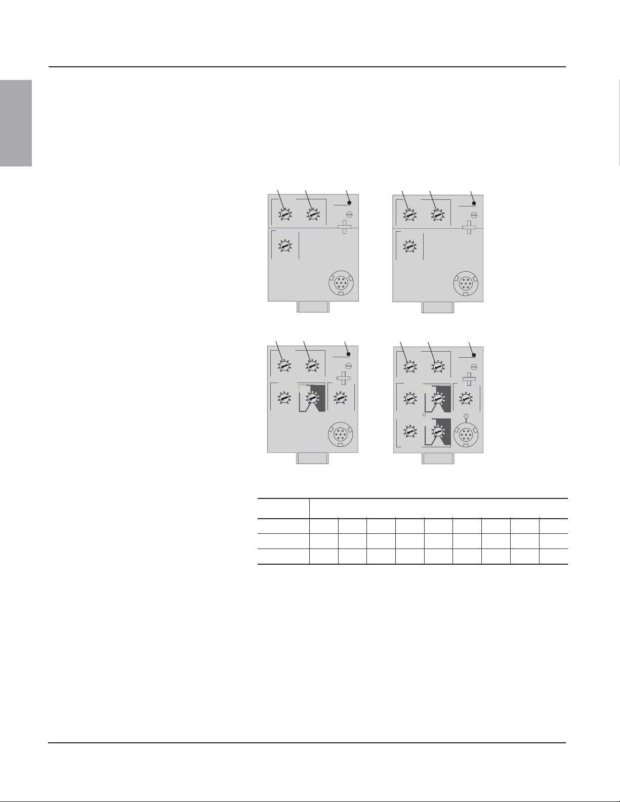
Long-Time Protection
Long-time protection protects equipment against
overloads.
• Long-time protection is standard on all trip
units.
• The long-time pickup (Ir) (A) sets the
maximum current level (based on sensor
plug rating In) which the circuit breaker can
continuously carry. If current exceeds this
value, circuit breaker will trip after the preset
time delay. The long-time pickup (Ir) is
adjustable from 0.4–1.0 times the sensor
plug rating (In).
• The long-time delay (tr) (B) sets the length of
the time that the circuit breaker will carry an
overcurrent (below the short-time or
instantaneous pickup current level) before
tripping. See Table 1 for delay settings.
• Both long-time pickup and long-time delay
are on the field-replaceable adjustable rating
plug. To change settings to more precisely
match the application, various rating plugs
are available. For instructions on replacing
the rating plug, see Section
5 —Adjustable
Rating Plug Replacement.
• For Masterpact™ NT and NW circuit
breakers, the In value can be changed by
replacing the sensor plug below the trip unit.
For further information, see the instructions
packed with the sensor plug replacement kit.
• The overload indicator light (C) indicates that
the Ir long-time pickup threshold has been
exceeded.
• Long-time protection uses true RMS
measurement.
Thermal imaging provides continuous
temperature rise status of the wiring, both before
and after the device trips. This allows the circuit
breaker to respond to a series of overload
conditions which could cause conductor
overheating, but would go undetected if the
long-time circuit was cleared every time the load
dropped below the pickup setting or after every
tripping event.
NOTE: Micrologic trip units are powered from the circuit to always provide
fault protection. All other functions (display, metering, communications, etc.)
require external power. See 15 for more information.
Figure 7: Long-Time Protection Switches
Micrologic 2.0A Trip Unit
B
A
Micrologic 5.0A Trip Unit
B
A
C
C
Micrologic 3.0A Trip Unit
B
A
Micrologic 6.0A Trip Unit
B
A
C
C
Table 1: Micrologic Trip Unit Long-Time Delay Values
1
Setting
Long-Time Delay in Seconds
tr at 1.5 x Ir 12.5 25 50 100 200 300 400 500 600
tr at 6 x Ir 0.51 2 4 8 12162024
3
tr at 7.2 x Ir 0.34
1
Ir = In x long-time pickup. In = sensor rating. Trip threshold between 1.05 and 1.20 Ir.
2
Time-delay accuracy +0/-20%
3
For Micrologic 5.0A and 6.0A trip units, when tsd is set to 0.4 on or 4.0 off, then tr = 0.5 instead of 0.34.
0.69 1.38 2.7 5.5 8.3 11 13.8 16.6
2
NOTE: If checking trip times, wait a minimum of 15 minutes after circuit
breaker trips before resetting to allow the thermal imaging to reset
completely to zero or use a full-function test kit to defeat the thermal
imaging.
© 1999–2012 Schneider Electric All Rights Reserved10-EN
Page 13

48049-136-05 Micrologic™ 2.0A, 3.0A, 5.0A, and 6.0A Electronic Trip Units
A
B
.4
.5
.6
.7.8.9
.95
.98
1
delay
short tim
e
I itsd
(s)
on I2t
.
2
.
3
.
4
.
4
.
1
.
2
.
3
.
1
0
off
instantaneous
long time
alarm
Ir
x In
ground fault
B
C
D
E
F
G
H
J
Ig tg
(s)
on I2t
.
2
.
3
.
4
.
4
.
1
.
2
.
3
.
1
0
off
A
.5
1
2
4
8
12
16
20
tr
(s)
@
6 Ir
24
setting
x Ir
2
2.5
3
4
5
6
8
10
Isd
1.
5
x In
3
4
5
8
10
12
15
off
2
test
06133351
Rev. 01, 07/2012 Section 1—General Information
Short-Time Protection
Short-time protection protects equipment
against short circuits.
• Short-time protection is standard on 2.0A,
5.0A and 6.0A trip units. It is not available on
3.0A trip units.
• Short-time protection is based on the long-
time pickup (Ir).
• The short-time pickup (Isd) (A) sets current
level (below instantaneous trip level) at
which circuit breaker will trip after the preset
time delay.
• The short-time delay (tsd) (B) sets the length
of time that the circuit breaker will carry an
overcurrent above the short-time pickup
current level before tripping. It is adjustable
on the 5.0A and 6.0A trip unit and factory set
to zero on the 2.0A trip unit.
• The I
2
t on/I2t off option provides improved
selectivity with downstream protective
devices:
—With I
2
t off selected, fixed time delay is
provided.
2
—With I
t on selected, inverse time I2t
protection is provided up to 10 x Ir.
Above 10 x Ir, fixed time delay is
provided.
• Intermittent currents in the short-time tripping
range which do not last sufficiently long to
trigger a trip are accumulated and shorten
the trip delay appropriately.
• Short-time protection can be zone-selective
interlocked (ZSI) with upstream or
downstream circuit breakers.
• Setting tsd to the 0 setting turns off zone-
selective interlocking.
• Short-time protection uses true RMS
measurement.
• Short-time pickup and delay can be adjusted
to provide selectivity with upstream or
downstream circuit breakers.
Figure 8: Short-Time Protection Switches
Micrologic 5.0A Trip Unit
Ir
06133204
.6
.5
Isd
2.5
2
1.
long time
.7.8.9
.4
x In
short tim
3
5
x Ir
setting
tr
(s)
.95
2
1
.98
1
e
4
(s)
5
6
.3
.2
8
10
on I2t
alarm
8
4
12
16
20
24
.5
@
6 Ir
instantaneous
I itsd
.4
.3
.4
6
4
.2
3
.1
0
.1
2
off
delay
8
10
12
15
off
x In
Micrologic 6.0A Trip Unit
A
B
Table 2: Micrologic Trip Unit Short-Time Delay Values
Setting Short-Time Delay
I2t off (Isd at 10 Ir) (seconds) 0 0.1 0.2 0.3 0.4
2
t on (Isd at 10 Ir) (seconds) 0.1 0.2 0.3 0.4
I
tsd (min. trip) (milliseconds) 20 80 140 230 350
tsd (max. trip) (milliseconds) 80 140 200 320 500
NOTE: Use I2t off with ZSI for proper coordination. Using I2t on with ZSI is
not recommended as the delay in the upstream device receiving a restraint
signal could result in the trip unit tripping in a time shorter than the
published trip curve.
ENGLISH
© 1999–2012 Schneider Electric All Rights Reserved
11-EN
Page 14

Micrologic™ 2.0A, 3.0A, 5.0A, and 6.0A Electronic Trip Units 48049-136-05
Section 1—General Information Rev. 01, 07/2012
ENGLISH
Instantaneous Protection
Instantaneous protection protects equipment
against short circuits with no intentional time
delay.
• Instantaneous protection (Ii) (A) is standard
• Instantaneous protection on 2.0A trip units is
• Instantaneous protection on the 3.0A, 5.0A
• Instantaneous protection on the 2.0A trip unit
• Circuit breaker open command is issued as
• Instantaneous protection uses peak current
• When instantaneous protection switch is set
on the 3.0A, 5.0A and 6.0A trip units.
achieved by using short-time protection (Isd)
with the short-time delay factory set to 0
(zero).
and 6.0A trip units is based on the circuit
breaker sensor rating (In).
is based on the long-time pickup setting (Ir).
soon as threshold current is exceeded.
measurement.
to off, the instantaneous protection is
disabled.
Figure 9: Instantaneous Protection Switches
Micrologic 2.0A Trip Unit
long time
tr
Ir
(s)
.7.8.9
06134243
.6
.95
2
1
.5
.98
.4
1
x In
instantaneous
Isd
4
3
5
2.5
6
2
8
5
1.
10
setting
x Ir
A
Micrologic 5.0A Trip Unit
long time
Ir
tr
(s)
.7.8.9
06133204
.6
.95
2
1
.5
.98
.4
1
.5
x In
e
short tim
Isd
4
(s)
5
3
6
2.5
.3
.2
2
8
.1
1.
5
10
on I2t
x Ir
setting
alarm
8
4
12
16
20
24
.5
@ 6 Ir
alarm
8
4
12
16
20
24
@
6 Ir
instantaneous
I itsd
8
.4
.3
.4
delay
10
6
4
12
.2
3
15
.1
off
0
2
off
x In
Micrologic 3.0A Trip Unit
long time
Ir
.7.8.9
06133203
.6
.5
.4
x In
instantaneous
Ii
5
4
3
2
1.
5
A
setting
x In
Micrologic 6.0A Trip Unit
long time
Ir
.7.8.9
06133351
.6
.5
.4
x In
short time
Isd
4
3
2.5
2
1.
A
5
x Ir
setting
Ig tg
E
D
C
B
A
ground fault
tr
(s)
4
.95
2
1
.98
1
.5
6
8
10
12
tr
(s)
4
.95
2
1
.98
1
.5
(s)
.
4
5
.
3
6
.
2
8
.
1
10
on I2t
(s)
.
4
F
.
3
G
.
2
H
.
1
J
on I2t
alarm
8
12
16
20
24
@ 6 Ir
alarm
8
12
16
20
24
6 Ir
@
instantaneous
I itsd
.
4
8
.
3
10
5
.
2
4
12
.
1
3
15
0
2
delay
.
4
test
.
3
.
2
.
1
0
off
off
off
x In
A
Table 3: Micrologic Instantaneous Values
Setting Interruption Current
2.0A Isd (= Ir x..) 1.522.53456810
Ii (= In x..) 1.52345681012
3.0A
Ii (= In x..) 23468101215off
5.0A
Ii (= In x..) 23468101215off
6.0A
Ii = UL and ANSI instantaneous
Isd = IEC instantaneous (short-time with zero delay)
In = sensor rating
Ir = long-time pickup
© 1999–2012 Schneider Electric All Rights Reserved12-EN
Page 15

48049-136-05 Micrologic™ 2.0A, 3.0A, 5.0A, and 6.0A Electronic Trip Units
A
B
Micrologic 6.0A Trip Unit
delay
short tim
e
I itsd
instantaneous
long time
alarm
test
800
earth leakage
1
2
3
5
7
10
20
30
ΔI
(ms)
60
.5
140
230
350
IΔn
(A)
setting
x Ir
2
2.5
3
4
5
6
8
10
Isd
1.
5
on
I2t
.
2
.
3
.
4
.
4
.
1
.
2
.
3
.
1
0
x In
2
2.5
3
4
5
6
8
10
1.
5
.5
1
2
4
8
12
16
20
tr
(s)
@
6 Ir
24
.4
.5
.6
.7.8.9
.95
.98
1
Ir
x In
40
%
%
100
06133352
Rev. 01, 07/2012 Section 1—General Information
Ground-Fault Protection
Equipment ground-fault protection protects
conductors against overheating and faults from
ground-fault currents (d1200 A).
• Equipment ground-fault protection is
standard on 6.0A trip units.
• Ground-fault pickup (Ig) (A) sets ground
current level where circuit breaker will trip
after the preset time delay.
• Ground-fault delay (tg) (B) sets the length of
time that the circuit breaker will carry a
ground-fault current above the ground-fault
pickup current level before tripping.
• Equipment ground-fault protection can be
zone-selective interlocked (ZSI) with
upstream or downstream circuit breakers.
• Setting the ground-fault delay (tg) to the 0
setting turns off zone-selective interlocking.
• Neutral protection and equipment ground-
fault protection are independent and can
operate concurrently.
Figure 10: Ground-Fault Protection Switches
long time
Ir
.7.8.9
06133351
.6
.5
.4
x In
short time
Isd
3
2.5
2
1.
5
x Ir
setting
Ig tg
D
C
B
A
ground fault
tr
(s)
.95
.98
1
4
(s)
5
.
6
.
8
10
on I2t
E
(s)
F
.
G
.
H
J
on I2t
alarm
8
4
12
16
2
1
20
24
.5
@
6 Ir
instantaneous
I itsd
.
4
8
.
3
.
4
3
2
.
1
delay
.
4
.
4
3
2
.
1
10
5
.
2
4
12
.
1
3
15
0
2
off
off
x In
test
.
3
.
2
.
1
0
off
Table 4: Micrologic Trip Unit Ground-Fault Pickup Values
Ig (= In x....) ABCDEFG H J
In d 400 A 0.3 0.3 0.4 0.5 0.6 0.7 0.8 0.9 1
400 A < In d 1200 A 0.2 0.3 0.4 0.5 0.6 0.7 0.8 0.9 1
In > 1200 A 500 A 640 A 720 A 800 A 880 A 960 A 1040 A 1120 A 1200 A
In = sensor rating.
Ig = ground-fault pickup.
Table 5: Micrologic Trip Unit Ground-Fault Delay Values
ENGLISH
Indicator Lights
Overload Indicator Light
The overload indicator light (A) lights when the Ir
long-time pickup level has been exceeded (over
100% on the bar graph).
Setting Ground-Fault Delay
I2t off (ms at In) (seconds) 0 0.1 0.2 0.3 0.4
2
t on (ms at In) (seconds) – 0.1 0.2 0.3 0.4
I
tsd (min. trip) (milliseconds) 20 80 140 230 350
tsd (max. trip) (milliseconds) 80 140 200 320 500
NOTE: Use I2t off with ZSI for proper coordination. Using I2t on with ZSI is
not recommended as the delay in the upstream device receiving a restraint
signal could result in the trip unit tripping in a time shorter than the
published trip curve.
Figure 11: Overload Indicator Light
A
© 1999–2012 Schneider Electric All Rights Reserved
13-EN
Page 16

Micrologic™ 2.0A, 3.0A, 5.0A, and 6.0A Electronic Trip Units 48049-136-05
Micrologic 6.0 A
06133245
menu
40
100
%
%
Section 1—General Information Rev. 01, 07/2012
ENGLISH
Trip Indicator Lights
The Ir trip indicator light (A) lights when a trip
occurs because the Ir long-time pickup level was
exceeded.
The Isd/Ii trip indicator light (B) lights when a trip
occurs because the Isd short-time pickup or the
Ii instantaneous pickup was exceeded.
The Ig trip indicator light (C) lights when a trip
occurs because the Ig ground fault pickup was
exceeded.
The Ap self-protection indicator light (D) lights
when the trip unit overheats, the instantaneous
override level is exceeded, or a trip unit power
supply failure occurs.
Ammeter
The ammeter monitors and displays the circuit
breaker currents. An alphanumeric screen (A)
continuously displays the phase at the highest
load. Navigation buttons (B) can be pressed to
display the various monitored currents.
The process of checking the ammeter values
can be stopped at any time. After several
seconds, Micrologic trip units automatically
return to displaying the phase at the highest
load.
See the following section for addition information
concerning the ammeter.
Figure 12: Trip Indicator Lights
C
B
A
D
Figure 13: Ammeter
A
B
Trip Unit Testing Trip unit functions can be tested using primary injection testing or secondary
injection testing.
Micrologic Trip Unit Configuration
Control Power The A trip unit was designed to be used with or without an external 24 Vdc
Table 6: Pickup Values
Sensor Plug Value
(In)
100–250 A 30% of Sensor Rating
400–1200 A 20% of Sensor Rating
1600–6300 A 500 A
Minimum Ground-Fault
Pickup
power supply.
The following will be powered and functional even if the trip unit is not
externally powered:
• Fault protection for LSIG functions. The A trip unit is fully circuit powered
for fault protection.
• LED trip indication (powered by an onboard battery). The battery’s only
function is to provide LED indication if all other power is off
• All display functions and trip unit features power-up with current flow on
one phase greater than or equal to the values in Table 6.
• Ground-fault push-to-trip button works for testing ground fault with
current flow on one phase greater than or equal to the values in Table 6.
The ground-fault push-to-trip is also functional if a Hand-Held Test Kit or
Full-Function Test Kit is powering the trip unit.
© 1999–2012 Schneider Electric All Rights Reserved14-EN
Page 17

48049-136-05 Micrologic™ 2.0A, 3.0A, 5.0A, and 6.0A Electronic Trip Units
CAUTION
Connections UC3
F1 (-)
F2 (+)
24 Vdc
Rev. 01, 07/2012 Section 1—General Information
The following will be powered and functional with external power:
• All of the above functions which are functional without external power.
• Ammeter and bar graph displays are functional with or without current
flowing through the circuit breaker. With current flow between 0 and 20%
of sensor value, the ammeter may not be accurate.
• Trip settings and max. current readings can be accessed on the display
be pressing the navigation buttons with or without current flowing
through the circuit breaker.
• Ground-fault push-to-trip button works for testing ground fault with or
without current flowing through the circuit breaker.
• Optional Modbus communications are functional, using a separate 24
Vdc power supply for the circuit breaker communications module. This
separate 24 Vdc power supply is required to maintain the isolation
between the trip unit and communications.
The ground-fault push-to-trip is also functional if a Hand-Held Test Kit or
Full-Function Test Kit is powering the trip unit.
External Power Supply
The trip unit display can be powered by a 24 Vdc external power supply.
Table 7: Power Supply Specifications
ENGLISH
HAZARD OF SHOCK, ARC FLASH OR
EQUIPMENT DAMAGE
Trip unit and communication module must use
separate power supplies.
Failure to follow this instruction can result
in personal injury or equipment damage.
Function Specification
Power for Trip Unit Alone 24 Vdc, 50 mA
Minimum Input-to-Output Isolation 2400 V
Output (Including Max. 1% Ripple) ±5%
Dielectric Withstand (Input/Output) 3 kV rms
Connections
Power supply is used for graphic scree display when the circuit breaker is
open or not carrying current.
© 1999–2012 Schneider Electric All Rights Reserved
15-EN
Page 18

Micrologic™ 2.0A, 3.0A, 5.0A, and 6.0A Electronic Trip Units 48049-136-05
B
menu
40
100
%
%
0
%
A
Ir=
06133353
40
100
%
%
A
06133354
Section 2—Ammeter Rev. 01, 07/2012
Section 2—Ammeter
ENGLISH
Display NOTE: The ammeter display will function only if the trip unit is powered. The
trip unit is powered by the circuit breaker carrying more than 0.20 x In of
load current, by being connected to a 24 Vdc external power supply, or by
having the Full-Function Test Kit or Hand-Held Test Kit connected and on.
Even with external power supplied, current through the circuit breaker must
exceed 0.20 x In for the ammeter reading to be accurate to within 1.5%.
A. Alphanumeric screen: Displays ammeter
information
B. Bar graph: Displays currents using an LED
bar graph
C. Menu button: Used to navigate between the
various menus
D. Scroll button: Used to scroll to the next
screen in the menus
The default display is the current value of the
phase at the highest load.
If no information is displayed, contact the local
field office.
Ammeter Measurements
Micrologic A trip units measure the true RMS
value of currents. They provide continuous
current measurement from 0.2 to 20 x In with an
accuracy of 1.5% (including sensors). No
auxiliary source is needed where I > 0.2 x In.
The optional external power supply (24 Vdc)
makes it possible to display currents where
I < 0.2 x In and to store values of the interrupted
current.
A digital LCD screen continuously displays the
most heavily loaded phases (Imax) or displays
the Ia, Ib, Ic, Ig, and (on 4-pole circuit breakers
only) In stored current and setting values by
successively pressing the navigation button.
Figure 14: Ammeter
06133245
A
C
D
Accessing Information
Three different menus can be accessed:
A. Current measurements
Figure 15: Menus
A–Currents
B–Peak Currents
06133355
C–Switch Settings
Max
A
B. Stored peak current measurements
C. Switch settings
In addition, the ammeter can be used to address
the circuit breaker communication module
(BCM) in circuit breakers which have the
optional circuit breaker communication module
installed.
1.125 x Ir
1 x Ir
0.8 x Ir
0.6 x Ir
0.4 x Ir
%
100
%
40
© 1999–2012 Schneider Electric All Rights Reserved16-EN
100
4
%
Page 19

48049-136-05 Micrologic™ 2.0A, 3.0A, 5.0A, and 6.0A Electronic Trip Units
menu
u
33356
40
100
%
%
A
06133343
06134248
Rev. 01, 07/2012 Section 2—Ammeter
To access the next menu, press the menu
button (A). To access the next screen in a menu,
press the scroll button (B).
Current Menu
The current (default) menu displays:
A. Phase current (IA) in A phase
B. Phase current (IB) in B phase
C. Phase current (IC) in C phase
D. Ground-fault current (Ig) (Micrologic 6.0A trip
units only)
E. Neutral current (In)
To display next current, press scroll button.
NOTE: Neutral current is only displayed with a
4-pole circuit breaker with the neutral protection
set to half or full. Refer to bulletin 48041-082-03
for NC CT wiring guidelines.
Figure 16: Navigation Buttons
A
1
B
Figure 17: Current Menus
A–A-Phase Current (IA)
06133354
%
100
%
40
C–C-Phase Current (IC)
06134248
A
B–B-Phase Current (IB)
06133342
A
%
100
%
40
D–Ground-Fault Current (Ig)
ENGLISH
06134248
E–Neutral Current (In)
06133345
%
100
%
40
06134248
06134248
A
06133344
%
100
%
40
Return to A-Phase Current
06133354
%
100
%
40
A
A
06134248
© 1999–2012 Schneider Electric All Rights Reserved
17-EN
Page 20

Micrologic™ 2.0A, 3.0A, 5.0A, and 6.0A Electronic Trip Units 48049-136-05
40
100
%
%
A
Max
06133355
40
100
%
%
A
06133354
menu
06134247
06134248
40
100
%
%
A
Max
06133349
40
100
%
%
A
Max
06133346
C–Peak C-Phase Current (IpC)
06134248
E–Peak Neutral Current (Ipn)
Return to Peak A-Phase Current
Section 2—Ammeter Rev. 01, 07/2012
ENGLISH
Peak Menu
To access the peak menu:
1. Current menu is displayed.
2. Press menu button.
3. Peak menu appears.
To access menu screens, press scroll button.
The peak menu displays:
A. Peak current (IpA) in A phase
B. Peak current (IpB) in B phase
C. Peak current (IpC) in C phase
D. Peak ground-fault current (Ipg) (Micrologic
E. Peak neutral current (Ipn)
To display next peak current, press scroll button.
To reset a max value, scroll to the particular max
value screen to be reset and hold the scroll
button for three seconds.
6.0A trip unit only)
Figure 18: Access the Peak Menu
Current Menu
Figure 19: Peak Menus
A–Peak A-Phase Current (IpA)
06133355
100
40
Max
06134248
A
%
%
Peak Menu
B–Peak B-Phase Current (IpB)
06134248
06133347
100
40
D–Peak Ground-Fault Current (Ipg)
Max
06134248
A
%
%
06134248
06133348
100
40
06133355
100
40
Max
A
%
%
Max
A
%
%
© 1999–2012 Schneider Electric All Rights Reserved18-EN
Page 21

48049-136-05 Micrologic™ 2.0A, 3.0A, 5.0A, and 6.0A Electronic Trip Units
100
%
A
Ir=
06133353
100
%
A
Max
06133355
menu
06134247
Ii=
06133387
A
A
Ir=
06133382
06134248
s
tr=
06133383
A
Isd=
06133384
A
Ig=
06133388
s
tg=
06133389
06134248
06134248
D–tsd Setting
06134248
06134248
E–Ii Setting
F–Ig Setting
06134248
100
%
A
Ir=
06133353
menu
06134247
Switch Settings Menu
Current Menu
100
%
A
06133354
Rev. 01, 07/2012 Section 2—Ammeter
Switch Settings Menu
The switch settings menu displays the values at
which the switches are set.
To access the switch settings menu:
1. Peak menu is displayed.
2. Press menu button.
3. Switch settings menu will appear.
To access menu screens, press scroll button.
The switch settings menu displays:
A. Long-time pickup (Ir) setting
B. Long-time delay (tr) setting
C. Short-time pickup (Isd) setting
D. Short-time delay (tsd) setting
E. Instantaneous pickup (Ii) setting
F. Ground-fault pickup (Ig) setting (6.0A trip
units only)
G. Ground-fault delay (tg) setting (6.0A trip
units only)
To display next switch setting, press scroll
button.
Figure 20: Access the Switch Settings Menu
Peak Menu
Switch Settings Menu
Figure 21: Trip Unit Switch Settings
A–Ir Setting
C–Isd Setting
B–tr Setting
tsd=
06133385
06134248
s
06134248
ENGLISH
To return to the current menu:
1. Switch settings menu is displayed.
2. Press menu button.
3. Current menu will appear.
Or wait several seconds and ammeter will
automatically return to the current (i.e., default)
menu.
© 1999–2012 Schneider Electric All Rights Reserved
G–tg Setting
A–Ir Setting
06133382
Ir=
A
Figure 22: Return to Current Menu
19-EN
Page 22

Micrologic™ 2.0A, 3.0A, 5.0A, and 6.0A Electronic Trip Units 48049-136-05
06133205
33
06
06133207
06133208
0 Ir Isd
t
06134245
alarm
x Ir
2
2.5
3
4
5
6
8
10
1.5
setting
Isd
instantaneous
.4
.5
.6
.7.8.9
.95
.98
1
long time
Ir
x In
06134251
Section 3—Operation Rev. 01, 07/2012
Section 3—Operation
ENGLISH
Switch Setting Adjustment
1. Open switch cover (A).
2. Adjust the appropriate switches (B) to
desired values.
3. Replace switch cover. Use wire seal
MICROTUSEAL (C, not provided), if
necessary, to provide tamper evidence.
Examples
Circuit breaker is rated 2000 A.
Figure 23: Adjust Switch Settings
2
1
A
B
Figure 24: Circuit Breaker Rating
C
Micrologic 2.0A Trip Unit
1. Set pickup levels.
In 2000 A
Figure 25: Set Pickup Levels
In = 2000 A
Ir = 0.7 x In = 1400 A
Isd = 2 x Ir = 2800 A
© 1999–2012 Schneider Electric All Rights Reserved20-EN
Page 23

48049-136-05 Micrologic™ 2.0A, 3.0A, 5.0A, and 6.0A Electronic Trip Units
long time
alarm
.5
1
2
4
8
12
16
20
tr
(s)
@
6 Ir
24
06133211
0 I
t
tr
06133212
6 x Ir
1 s
0 I
t
Ir
Ii
06133210
Ii = 3 x In = 6000 A
alarm
x In
2
3
4
5
6
8
10
12
1.5
setting
Ii
instantaneous
.4
.5
.6
.7.8.9
.95
.98
1
long time
Ir
x In
06133209
In = 2000 A
Ir = 0.7 x In = 1400 A
1400 A
6000 A
long time
alarm
.5
1
2
4
8
12
16
20
tr
(s)
@
6 Ir
24
06133211
0 I
t
tr
06133212
6 x Ir
1 s
06133213
.4
.5
.6
.7.8.9
.95
.98
1
setting
short tim
e
I i
x Ir
2
2.5
3
4
5
6
8
10
Isd
1.5
off
instantaneous
long time
alarm
Ir
x In
x In
3
4
6
8
10
12
15
off
2
Ii = 6 x In = 12000 A
In = 2000 A
Ir = 0.7 x In = 1400 A
Isd = 2 x Ir = 2800 A
1400 A
2800 A
12000 A
Rev. 01, 07/2012 Section 3—Operation
2. Set time delay. Figure 26: Set Time Delay
tr = 1 s (at 6 x Ir)
ENGLISH
Micrologic 3.0A Trip Unit
Figure 27: Set Pickup Levels
1. Set pickup levels.
2. Set time delay. Figure 28: Set Time Delay
tr = 1 s (at 6 x Ir)
Micrologic 5.0A Trip Unit
1. Set pickup levels.
© 1999–2012 Schneider Electric All Rights Reserved
Figure 29: Set Pickup Levels
t
Ir
06133214
Isd
0
Ii
I
21-EN
Page 24

Micrologic™ 2.0A, 3.0A, 5.0A, and 6.0A Electronic Trip Units 48049-136-05
tr
tsd
0
t
06133217
6 x Ir
1 s
10 x Ir
0.2 s
Ir
Isd
Ii
0
I
t
06133214
0
t
g
33359
A
short time
instantaneous
long time
alarm
ground faul
t
.5
1
2
4
8
12
16
20
tr
(s)
@
6 Ir
24
delay
tsd
(s)
on I2t
.2
.3
.4
.4
.1
.2
.3
.1
0
off
tg
(s)
on I2t
.2
.3
.4
.4
.1
.2
.3
.1
0
off
I2t on I2t off
06133358
0
t
g
3336
Section 3—Operation Rev. 01, 07/2012
ENGLISH
2. Set time delay. Figure 30: Set Time Delays
Micrologic 6.0A Trip Unit
1. Set pickup levels.
06133215
long time
short time
tr
(s)
4
2
1
.5
tsd
.
.
3
.
2
.
1
on
alarm
8
12
16
20
24
6 Ir
@
.
4
.
3
4
.
2
.
1
0
2
I
t
delay
Figure 31: Set Pickup Levels
Ir
06133357
.6
.5
Is
2.5
Ig
long time
.7.8.9
.4
short time
3
2
1.5
setting
D
C
B
A
gr
ound fault
x In
x Ir
.95
.98
1
4
5
6
8
1
E
F
G
H
J
alarm
instantaneous
I
8
6
4
3
2
x In
10
12
15
off
tr = 1 s (at 6 x Ir)
tsd = 0.2 s I2t on
I2t on I2t off
In = 2000 A
Ir = 0.7 x In = 1400 A
Ii = 6 x In = 12000 A
Isd = 2 x Ir = 2800 A
BoIg = 640 A
1400 A
1
2800 A
12000 A
I
2. Set time delays. Figure 32: Set Pickup Levels
tr = 1 s (at 6 x Ir)
tsd = 0.2 s I2t on
tg = 0.2 s I2t on
© 1999–2012 Schneider Electric All Rights Reserved22-EN
0.2 s
0.2 s
1 s
t
06133217
0
1
1
640
6 x Ir
tr
10 x Ir
t
tsd
I
Page 25

48049-136-05 Micrologic™ 2.0A, 3.0A, 5.0A, and 6.0A Electronic Trip Units
Rev. 01, 07/2012 Section 3—Operation
Zone-Selective Interlocking (ZSI)
The number of devices which can be interlocked
are shown in Table 8.
Table 8: ZSI Combinations
Upstream Device
(receives input from RIM)
Downstream Device
(sends output to RIM)
Micrologic #.0x Trip Units
Square D Micrologic Series B Trip Units
Square D GC-100 Ground-Fault Relay
for Equipment Protection
Square D GC-200 Ground-Fault Relay
for Equipment Protection
Micrologic #.0x Trip Units
Square D Micrologic Series B Trip Units
Square D GC-100 Ground-Fault Relay
for Equipment Protection
Square D GC-200 Ground-Fault Relay for
Equipment Protection
Merlin Gerin STR58 Trip Units
Federal Pioneer USRC and USRCM Trip Units
15R R 1515R
R26RRR15
RR7 RRR
15R R 1515R
ENGLISH
Circuit breaker terminals are shipped with
terminals Z3, Z4 and Z5 jumpered to selfrestrain the short-time and ground-fault
functions. Remove the jumpers when activating
zone-selective interlocking.
Merlin Gerin STR58 Trip Units
Merlin Gerin STR53 Trip Units
Federal Pioneer USRC and USRCM Trip
Units
Square D Add-On Ground Fault Module
for Equipment Protection
R—RIM module is required to restrain any devices.
Numerical References—Maximum number of upstream circuit breakers which can be restrained
without requiring a RIM Module.
15R R 1515R
15R R 1515R
R15RRR15
R5 RRRR
Figure 33: Jumpered Terminals
UC1
Z5
M1
Z3
Z4
Z2
Z1
Auxiliary Connections
© 1999–2012 Schneider Electric All Rights Reserved
23-EN
Page 26

Micrologic™ 2.0A, 3.0A, 5.0A, and 6.0A Electronic Trip Units 48049-136-05
100
%
A
06133354
%
06133703
u
33
0
Section 3—Operation Rev. 01, 07/2012
ENGLISH
interlocking.
Communication Module values
If the optional circuit breaker communication
module (BCM) is installed, use the ammeter to
set communication module values.
To access the communication module menu:
1. Current menu is displayed.
2. Simultaneously press both menu button and
3. Communication module addressing menu
Wire circuit breakers for zone-selective
scroll button down for three seconds.
will appear.
Figure 34: ZSI Wiring Example
UC1
Z5
M1
Z3
Z4
Z2
Secondary
Connector
Position
Z1
Z2
Z3
Z4
Z5
Z1
Auxiliary
Connections 1
Description
ZSI out signal
ZSI out
ZSI in signal
ZSI in short time
ZSI in ground fault
UC1
Z5
M1
Z3
Z4
Z2
Z1
Auxiliary
Connections 2
Figure 35: Access Communication Module Menu
Current Menu
7
7
men
1
Communications Address
UC1
Z5
M1
Z3
Z4
Z2
Z1
Auxiliary
Connections 3
© 1999–2012 Schneider Electric All Rights Reserved24-EN
Page 27

48049-136-05 Micrologic™ 2.0A, 3.0A, 5.0A, and 6.0A Electronic Trip Units
06133703
06134248
Communications Address
06133704
06133704
06133705
06134248
06133705
06134888
Parity
Language
06134248
06134888
06134248
Rev. 01, 07/2012 Section 3—Operation
Set communication module values:
1. Press and release scroll button to sequence
addresses (1 through 47). When the correct
address number is reached, enter the value
by pressing and holding scroll button until
the display stops flashing.
Baud rate screen will appear after address
has been entered.
2. Press and release scroll button to sequence
baud rates (4.8k, 9.6k or 19.2k). When the
desired baud rate appears, enter the value
by pressing and holding scroll button until
the display stops flashing.
Parity screen will appear after baud rate has
been entered.
3. Press and release scroll button to sequence
parities (E [even] or n [none]). When the
desired parity appears, enter the value by
pressing and holding scroll button until the
display stops flashing.
Languages screen will appear after parity
has been entered.
4. Press and release scroll button to scroll
through languages (French [Fr], US English
[En US], UK English [En], German [d],
Spanish [SP] or Italian [It]). When the
desired language appears, enter the value
by pressing and holding scroll button until
the display stops flashing.
Ammeter display will return to the default
screen after language is entered.
After the communication module values have
been set, ammeter will automatically return to
the current (i.e., default) menu.
After setting circuit breaker communication
module values, drawout circuit breakers must
have the cradle communication module, if
available, activated. For drawout circuit
breakers, refer to the cradle communication
module instructions to complete setup.
Figure 36: Set Communication Module Values
Baud Rate
06134248
Baud Rate
06134248
06134248
Language
06134248
Parity
ENGLISH
© 1999–2012 Schneider Electric All Rights Reserved
25-EN
Page 28

Micrologic™ 2.0A, 3.0A, 5.0A, and 6.0A Electronic Trip Units 48049-136-05
A
Ir=
06133382
menu
06134247
s
tr=
06133383
06134248
A
Isd=
06133384
s
tsd=
06133385
06134248
Ii=
06133387
A
06134248
A
Ig=
06133388
06134248
s
tg=
06133389
06133205
06133218
Section 3—Operation Rev. 01, 07/2012
ENGLISH
Trip Unit Settings Check
Use the ammeter switch setting menu to check
the trip unit settings.
1. Press menu button twice.
2. Switch settings menu will appear.
3. Press scroll button to advance to next
4. After checking trip unit settings, press menu
screen.
button once to return to main menu.
Table 9: Trip Unit Settings
Setting Window 2.0A 3.0A 5.0A 6.0A
menu
Ir
tr
Isd
tsd
Long-Time
Pickup
Long-Time
Delay
Short-Time
Pickup
Short-Time
Delay
06134247
XXXX
06134248
XXXX
XXX
06134248
XX
Trip Unit Operation Verification
Use a test kit connected to the trip unit test plug
receptacle (A) to verify trip unit is functioning as
desired. See instructions shipped with test kit to
perform verification tests.
Instantaneous
Ii
Pickup
Ground-Fault
Ig
Pickup
Ground-Fault
tg
Delay
Figure 37: Verify Trip Unit Operation
XXX
X
X
A
© 1999–2012 Schneider Electric All Rights Reserved26-EN
Page 29

48049-136-05 Micrologic™ 2.0A, 3.0A, 5.0A, and 6.0A Electronic Trip Units
06134249
M
icro
log
ic
6.0 A
4
0
1
0
0
%
%
men
u
06133379
A
B
Charged
Half-Charged
Change Battery
Rev. 01, 07/2012 Section 3—Operation
Equipment Ground-Fault Trip
Functions Testing
Paragraph 230-95 (c) of the National Electrical
Code requires that all equipment ground-fault
protection systems be tested when first installed.
With the circuit breaker closed, test the groundfault (Micrologic 6.0A trip unit only) trip
functions. For instructions on how to close circuit
breaker, refer to the circuit breaker installation
instructions shipped with the circuit breaker.
1. Press the ground-fault test button (A). Circuit
breaker should trip.
2. If circuit breaker does not trip, contact the
local field office.
Trip Unit Resetting
When the circuit breaker trips, the fault indicator
will remain lit until the trip unit is reset.
Press the reset/test button (A) to reset the trip
unit after trip.
Do not return circuit breaker to service until cause
of trip is determined. For more information, refer
to the circuit breaker installation instructions
shipped with the circuit breaker.
NOTE: Trip unit must be powered to test ground-fault trip function. The trip
unit is powered if the circuit breaker is carrying more than 0.20 x In of load
current, if the 24 Vdc external power supply is connected or if the FullFunction Test Kit or Hand-Held Test Kit is connected and on.
Figure 38: Test Equipment Ground-Fault Trip Function
A
Figure 39: Reset Trip Unit
Micrologic 6.0
A
ENGLISH
Trip Unit Status Check
To check trip unit battery and trip indicators,
press the test/reset button (A).
• All trip indicators (B) will light up
• Battery status will be displayed
• If no battery status is displayed, there is no
battery installed.
• The battery bar graph reading is valid after
the reset button has been released.
• If the battery bar graph shows the battery
needs to be changed, use Square D battery
catalog number S33593:
— lithium battery
— 1.2AA, 3.6 V, 800 ma/h
For instructions on replacing battery, see
Section 6—Battery Replacement.
© 1999–2012 Schneider Electric All Rights Reserved
NOTE: Trip unit must be powered to test battery. The trip unit is powered if
the circuit breaker is carrying more than 0.20 x In of load current, if the 24
Vdc external power supply is connected or if the Full-Function Test Kit or
Hand-Held Test Kit is connected and on.
Figure 40: Check Trip Unit Status
Micrologic 6.0
06133379
27-EN
Page 30

Micrologic™ 2.0A, 3.0A, 5.0A, and 6.0A Electronic Trip Units 48049-136-05
DANGER
Section 4—Trip Unit Replacement Rev. 01, 07/2012
Section 4—Trip Unit Replacement
ENGLISH
Trip unit replacement must be done by qualified
persons, as defined by the National Electric
Code, who are familiar with the installation and
maintenance of power circuit breakers.
Before replacing trip unit, confirm that the circuit
breaker is in good working condition. If the
condition of the circuit breaker is unknown, do
not proceed. For assistance in evaluating the
condition of the circuit breaker, call Technical
Support.
Read this entire section before starting the
replacement procedure.
NOTE: If trip unit being replaced is a Micrologic
2.0, 3.0 or 5.0 trip unit, order connector block
S33101 and circuit breaker or cradle wiring
harness if necessary.
HAZARD OF ELECTRIC SHOCK, EXPLOSION, OR ARC FLASH
• Failure to follow these instructions for installation, trip test and primary
injection testing may result in the failure of some or all protective function.
• Apply appropriate personal protective equipment (PPE) and follow safe
electrical work practices. See NFPA 70E or CSA Z462.
• Replacement/upgrading of a trip unit in the field must be done by
qualified persons, as defined by the National Electric Code, who are
familiar with the installation and maintenance of power circuit breakers.
• Before replacing/upgrading trip unit, confirm that the circuit breaker is in
good working condition. If the condition of the circuit breaker is unknown,
do not proceed. For assistance in evaluating the condition of the circuit
breaker, call Technical Support.
• If the circuit breaker fails to function properly in any manner upon
completion of the trip unit installation, immediately remove the circuit
breaker from service and call Field Services.
• Turn off all power supplying this equipment before working on or inside
equipment. Follow instructions shipped with circuit breaker to disconnect
and reconnect circuit breaker.
• Replace all devices, doors and covers before returning equipment to
service.
Failure to follow this instruction will result in death or serious injury.
Required Tools • Torque-controlled screwdriver, set at 7 in-lbs (0.8 N•m) ± 10%
(Lindstrom torque driver MAL500-2 or equivalent)
• Micrologic Full-Function Test Kit (part number S33595)
Preparation
Record Switch Settings Record all trip unit switch settings for later use.
Circuit Breaker Disconnection Disconnect circuit breaker as directed in the circuit breaker instruction
bulletin shipped with the circuit breaker. The circuit breaker must be
completely isolated. (For a drawout circuit breaker, place circuit breaker in
the disconnected position. For a fixed-mounted circuit breaker, all voltage
sources, including auxiliary power, must be disconnected.)
Circuit Breaker Accessory Cover
Removal
Remove circuit breaker accessory cover as directed in the Install
Accessories section of the circuit breaker instruction bulletin shipped with
the circuit breaker.
© 1999–2012 Schneider Electric All Rights Reserved28-EN
Page 31

48049-136-05 Micrologic™ 2.0A, 3.0A, 5.0A, and 6.0A Electronic Trip Units
s
et
t
ing
d
ela
y
sho
rt
t
i
m
e
I
i
x
Ir
2
2
.5
3
4
5
6
8
1
0
Is
d
1
.
5
t
sd
o
n
I
2
t
.
2
.
3
.
4
.
4
.
1
.
2
.
3
.
1
0
i
n
st
a
nt
ane
ous
x
In
2
2
.
5
3
4
5
6
8
1
0
1
.
5
.4
.5
.6
.7
.8
.
9
.95
.98
1
lon
g
ti
m
e
alar
m
Ir
x
In
.5
1
2
4
8
1
2
1
6
2
0
t
r
(s
)
@ 6
Ir
2
4
06133222
06134853
06134854
333
5
Micrologic 6.0 A
06133245
Rev. 01, 07/2012 Section 4—Trip Unit Replacement
Rating Plug Removal
A small Phillips screwdriver is needed to remove
the adjustable rating plug.
1. Open switch cover (A).
2. Unscrew adjustable rating plug mounting
screw (B).
3. Remove adjustable rating plug (C). Save for
installation in replacement trip unit.
Trip Unit Removal
1. Remove connector block (A) from top of trip
unit, if present.
2. Loosen two trip unit screws (B).
3. Slide out trip unit (C).
Figure 41: Remove Adjustable Rating Plug
B
06133205
06133221
m
r
a
l
a
e
m
i
8
t
g
2
r
n
t
1
o
l
)
4
6
(s
1
8
.
Ir
9
.
2
0
7
2
.
5
9
.
1
4
2
6
.
8
9
.
s
u
o
r
I
e
.5
n
6
a
t
@
n
a
t
5
.
s
n
i
1
4
.
n
I
x
i
I
4
5
3
e
m
6
i
t
t
r
4
3
.
o
.
sd
h
t
s
.5
2
4
.
8
2
.
d
Is
4
2
5
3
.
01.
1
1
.
3
6
5
2
In
.
5
x
0
.
2
8
1
.
2
t
2
I
0
1
n
o
y
a
l
e
5
.
d
1
Ir
x
g
n
i
t
t
se
A
Figure 42: Remove Existing Trip Unit
A
C
C
ENGLISH
B
Trip Unit Replacement
Battery Installation
If a new trip unit is being installed, install the trip
unit battery.
Install battery holder with battery (A) in trip unit,
observing the correct polarity as indicated on the
battery compartment.
Press test/reset button (A). All four indicator
lights (B) should light. If they do not light, check
polarity of battery and retest. If indicator lights
still do not light up when test/reset button is
pressed, stop installation and contact the local
sales office for factory authorized service
© 1999–2012 Schneider Electric All Rights Reserved
NOTE: Battery holder with battery is located under the side flap in the
cardboard box the trip unit is shipped in.
Figure 43: Install Battery
A
7
1
Figure 44: Trip Indicator Lights
B
A
29-EN
Page 32

Micrologic™ 2.0A, 3.0A, 5.0A, and 6.0A Electronic Trip Units 48049-136-05
06135453
Masterpact NW Circuit Breaker
A
C
B
NOTICE
Section 4—Trip Unit Replacement Rev. 01, 07/2012
ENGLISH
Trip Unit Installation
1. Inspect trip unit connector pins and surfaces.
2. Inspect trip unit mounting base on the circuit
3. For Masterpact NW circuit breaker only:
4. Align guide rail (B) on bottom of trip unit with
NOTE: The Masterpact NT and NW trip unit
mounting bases are shock mounted and
therefore can flex slightly.
If there is any damage, misaligned pins, or
contamination, stop installation and contact
the local sales office for factory authorized
service.
Figure 45: Install Trip Unit
breaker. Clear any debris from area and
check that all accessory wiring is properly
routed for the trip unit being installed. If there
is any damage or contamination, stop
installation and contact the local sales office
for factory authorized service.
06135451
Manually depress trip unit interlock (A) and
hold it in place during steps 4–6 below.
guide rail slot (C) on trip unit mounting base
in circuit breaker and gently slide the trip unit
in until it stops.
HAZARD OF EQUIPMENT DAMAGE
Check installation of trip unit to assure proper
connections and seating.
Failure to follow this instruction can result
in equipment damage or improper circuit
breaker tripping.
© 1999–2012 Schneider Electric All Rights Reserved30-EN
Page 33

48049-136-05 Micrologic™ 2.0A, 3.0A, 5.0A, and 6.0A Electronic Trip Units
A
C
B
7 lb-in
[0.8 N•m]
Must be
seated
Must be flush
s
et
ti
n
gd
ela
y
sho
r
t
ti
m
e
I i
x
I
r
2
2
.
5
3
4
5
6
8
10
I
s
d
1
.
5
t
sd
o
n
I
2
t
.
2
.
3
.
4
.
4
.
1
.
2
.
3
.
1
0
i
ns
t
a
n
t
a
n
e
o
us
x
I
n
2
2.5
3
4
5
6
8
1
0
1
.
5
t
e
s
t
.4
.5
.6
.7
.8
.9
.9
5
.98
1
lon
g
time
a
lar
m
Ir
x
In
.5
1
2
4
8
1
2
1
6
2
0
tr
(s
)
@
6
Ir
2
4
06133223
B
C
A
A
7 lb-in
[0.8 N•m]
Rev. 01, 07/2012 Section 4—Trip Unit Replacement
5. Align the trip unit so top mounting screw (A)
aligns with the top threaded insert and start
the screw by turning the screw two full
rotations.
6. Use a torque-controlled screwdriver to drive
the bottom screw (B) to 7 in-lbs (0.8 N•m) ±
10%. The back of the trip unit must be flush
with the trip unit mounting base.
7. Use a torque-controlled screwdriver to drive
the top screw to 7 in-lbs (0.8 N•m) ± 10%.
Mounting tab must be flush with the mounting
standoff and sensor plug.
NOTE: The face of the closed switch cover must
be flush with adjoining mounting base surfaces.
If these surfaces are not flush, stop installation
and contact the local sales office for factory
authorized service.
NOTE: If you are upgrading from a Micrologic
2.0, 3.0 or 5.0 trip unit, the connector block must
be ordered separately (Part Number S33101).
See instructions shipped with the connector
block for installation into circuit breaker.
8. Install connector block (C) into top of trip
unit.
Figure 46: Install Trip Unit
06134855
ENGLISH
06134856
9. Install adjustable rating plug into the trip unit.
a. Open switch cover (A) on new trip unit.
b. Inspect mounting area for debris and
contamination.
c. Gently push adjustable rating plug (B)
into new trip unit.
d. Tighten adjustable rating plug mounting
screw (C). The plug will be drawn into
position flush with front face as screw is
tightened.
10. Set trip unit switches to values recorded
above or per coordination study results.
11. Close switch cover (A).
Circuit Breaker Accessory Cover
Replacement
Figure 47: Install Adjustable Rating Plug
06134244
m
r
a
l
a
e
m
i
8
t
g
2
r
n
t
1
o
l
)
4
s
6
(
1
8
.
r
I
9
.
2
0
7
2
.
5
9
.
1
4
2
6
.
8
.9
s
u
o
r
I
e
.5
n
6
a
t
@
n
a
t
5
.
s
n
i
1
4
.
n
I
x
i
I
4
5
3
e
m
6
i
t
t
r
4
3
d
.
o
.
s
h
t
s
.5
2
4
.
8
2
.
d
Is
4
2
5
3
.
0
1
1
.
3
6
5
.
1
2
In
.
5
x
0
.
2
8
1
.
2
t
2
I
0
1
n
o
y
a
l
e
5
.
d
1
Ir
x
g
n
i
t
t
se
Replace circuit breaker accessory cover as directed in the Install
Accessories section of the circuit breaker instruction bulletin shipped with
the circuit breaker.
© 1999–2012 Schneider Electric All Rights Reserved
31-EN
Page 34

Micrologic™ 2.0A, 3.0A, 5.0A, and 6.0A Electronic Trip Units 48049-136-05
Section 4—Trip Unit Replacement Rev. 01, 07/2012
Trip Unit Installation Check
ENGLISH
Secondary Injection Testing
Field installation of a trip unit requires secondary injection testing with the
Full-Function Test Kit. to ensure that the newly-installed trip unit is
functioning properly. The test will require opening and closing the circuit
breaker. Follow the procedures outlined in the instruction bulletins shipped
with the circuit breaker and the test kit.
1. Make sure the circuit breaker is isolated from all upstream and
downstream devices.
2. Perform secondary injection testing as outlined in the instruction bulletin
shipped with the test kit. Verify that all applicable trip unit functions are
operating properly.
3. Repeat step 2 with the circuit breaker in the open position.
NOTE: The test kit states that the circuit breaker should be closed when
performing the test. Do not close the circuit breaker for this step.
4. If any test fails, do not put the circuit breaker into service and contact the
local sales office for factory authorization service.
Primary Injection Testing
Check Accessory Operation
Trip Unit Setup
Primary injection testing is recommended to ensure that all trip system
connections have been correctly made. Perform primary injection testing
per the instructions in the Field Testing and Maintenance Guide, bulletin
number 0600IB1201.
1. Installed accessories – Validate the proper operation of all installed
accessories. See the corresponding accessory instruction bulletins for
operational testing procedures.
2. Zone selective interlocking – If the circuit breaker is part of a ZSI system,
follow the zone selective interlocking test procedures as outlined in the
Full Function Test Kit instruction bulletin.
3. Communications – If communication modules exist, validate circuit
breaker has re-established communications with the supervisor.
1. If an auxiliary power supply is being used for the Micrologic trip unit,
reconnect the auxiliary power supply.
2. Reset the trip unit switches to original values, as recorded at the
beginning of this section.
Circuit Breaker Reconnection Reconnect circuit breaker as directed in the circuit breaker instruction
bulletin shipped with the circuit breaker.
© 1999–2012 Schneider Electric All Rights Reserved32-EN
Page 35

48049-136-05 Micrologic™ 2.0A, 3.0A, 5.0A, and 6.0A Electronic Trip Units
DANGER
s
e
t
t
ing
d
ela
y
s
ho
rt
t
i
m
e
I i
x
Ir
2
2
.5
3
4
5
6
8
1
0
Is
d
1
.
5
t
sd
o
n
I
2
t
.
2
.
3
.
4
.
4
.
1
.
2
.
3
.
1
0
i
n
st
a
n
t
ane
ous
x
I
n
2
2
.
5
3
4
5
6
8
1
0
1
.
5
.4
.5
.6
.7
.8
.
9
.9
5
.98
1
lon
g
ti
m
e
alar
m
Ir
x
In
.5
1
2
4
8
1
2
16
2
0
t
r
(s
)
@ 6
Ir
2
4
06133222
s
et
ti
n
g
d
ela
y
s
ho
r
t
ti
m
e
I
i
x
I
r
2
2
.
5
3
4
5
6
8
10
I
s
d
1.
5
t
sd
o
n
I
2
t
.
2
.
3
.
4
.
4
.
1
.
2
.
3
.
1
0
i
ns
t
a
n
t
a
n
e
o
us
x
I
n
2
2
.5
3
4
5
6
8
1
0
1
.
5
t
e
s
t
.4
.5
.6
.7
.8
.9
.9
5
.98
1
lo
n
g
time
a
larm
Ir
x
In
.5
1
2
4
8
1
2
1
6
2
0
tr
(s
)
@
6
Ir
2
4
06133223
.
4
.
5
.
6
.
7
.
8
.
9
.
9
5
.9
8
1
se
t
t
i
n
g
d
e
l
a
y
s
h
o
r
t
t
i
m
e
I
i
x
Ir
2
2
.
5
3
4
5
6
8
1
0
Is
d
1
.
5
t
sd
o
n
I
2
t
.
2
.
3
.
4
.
4
.
1
.
2
.
3
.
1
0
i
n
s
t
a
n
t
a
n
e
o
u
s
l
o
n
g
t
i
m
e
a
l
a
r
m
I
r
x
I
n
.5
1
2
4
8
1
2
1
6
2
0
t
r
(
s
)
@
6
I
r
2
4
x
In
2
2
.5
3
4
5
6
8
1
0
1.
5
06134244
Rev. 01, 07/2012 Section 5—Adjustable Rating Plug Replacement
Section 5—Adjustable Rating Plug Replacement
NOTE: To select correct replacement rating
plug, see the product catalog.
NOTE: If adjustable rating plug is removed, the
circuit breaker will default to a long-time pickup
rating of 0.4 x In and a long-time delay at
whatever setting was selected before the rating
plug was removed.
Rating Plug Removal
1. Open circuit breaker contacts:
— For Masterpact NT and NW circuit
breakers, press the “Push to open”
button on the circuit breaker.
— For other circuit breakers, move handle
to the off (O) position.
2. Open switch cover (A).
3. Unscrew adjustable rating plug mounting
screw (B).
4. Remove adjustable rating plug (C).
HAZARD OF ELECTRIC SHOCK, EXPLOSION, OR ARC FLASH
• Apply appropriate personal protective equipment (PPE) and follow safe
electrical work practices. See NFPA 70E or CSA Z462.
• This equipment must be installed and serviced only by qualified electrical
personnel.
• Turn off all power supplying this equipment before working on or inside
equipment. Follow instructions shipped with circuit breaker to disconnect
and reconnect circuit breaker.
• Replace all devices, doors and covers before returning equipment to
service.
Failure to follow this instruction will result in death or serious injury.
Figure 48: Remove Adjustable Rating Plug
B
06133205
06133221
m
r
a
l
a
e
m
i
8
t
g
2
r
n
t
1
o
l
)
4
6
(s
1
.8
r
I
9
.
2
0
7
2
.
5
9
.
1
4
2
.6
8
9
.
s
u
o
r
I
e
.5
n
6
a
t
@
n
a
t
5
.
s
n
i
1
4
.
n
I
x
i
I
4
5
3
e
m
6
i
t
t
r
4
3
.
o
.
sd
h
t
s
.5
2
4
.
8
2
.
d
Is
4
2
5
3
.
0
1
1
.
3
6
5
1.
2
In
.
5
x
0
.
2
8
1
.
2
t
2
I
0
1
n
o
y
a
l
e
5
.
d
1
Ir
x
g
n
i
t
t
se
A
ENGLISH
C
New Rating Plug Installation
1. Inspect mounting area for debris and
contamination.
2. Gently push in new adjustable rating plug
(A).
3. Tighten adjustable rating plug mounting
screw (B).
4. Set the switches on the trip unit (see Section
3 —Operation).
5. Close switch cover (C).
© 1999–2012 Schneider Electric All Rights Reserved
Figure 49: Install New Adjustable Rating Plug
B
A
C
33-EN
Page 36

Micrologic™ 2.0A, 3.0A, 5.0A, and 6.0A Electronic Trip Units 48049-136-05
DANGER
06123145
333
3
333
5
333
A
B
C
Section 6—Battery Replacement Rev. 01, 07/2012
Section 6—Battery Replacement
ENGLISH
Circuit Breaker Disconnection
Disconnect circuit breaker as directed in the
circuit breaker instruction bulletin shipped with
the circuit breaker.
Circuit Breaker Accessory Cover
Removal
Remove circuit breaker accessory cover as
directed in the Install Accessories section of the
circuit breaker instruction bulletin shipped with
the circuit breaker.
Withstand Module Shifting
NOTE: R-frame and NS1600b–NS3200 circuit
breakers only.
Loosen screws (A) securing withstand module
(B). Swing module to side to access trip unit
battery cover. Do not remove withstand module
connector.
HAZARD OF ELECTRIC SHOCK, EXPLOSION, OR ARC FLASH
• Apply appropriate personal protective equipment (PPE) and follow safe
electrical work practices. See NFPA 70E or CSA Z462.
• This equipment must be installed and serviced only by qualified electrical
personnel.
• Turn off all power supplying this equipment before working on or inside
equipment. Follow instructions shipped with circuit breaker to disconnect
and reconnect circuit breaker.
• Replace all devices, doors and covers before returning equipment to
service.
Failure to follow this instruction will result in death or serious injury.
Figure 50: Shift Withstand Module
B
Battery Replacement
1. Insert small screwdriver blade into battery
housing cover notch and rotate to slide
battery housing cover (A) out of trip unit.
2. Remove battery (A).
3. Insert new battery (B). Make sure that the
polarity is correct.
4. Replace battery housing cover (C).
A
Figure 51: Remove Battery Cover
A
Figure 52: Replace Battery
7
1
74
1
© 1999–2012 Schneider Electric All Rights Reserved34-EN
7
1
Page 37

48049-136-05 Micrologic™ 2.0A, 3.0A, 5.0A, and 6.0A Electronic Trip Units
06123146
Rev. 01, 07/2012 Section 6—Battery Replacement
Withstand Module Replacement
Figure 53: Replace Withstand Module
NOTE: R-frame and NS1600b–NS3200 circuit
breakers only.
Replace withstand module (A). Tighten screws
(B) securing withstand module.
B
4.4 lb-in
[0.5 N•m]
A
Circuit Breaker Accessory Cover
Replacement
Replace circuit breaker accessory cover as directed in the Install
Accessories section of the circuit breaker instruction bulletin shipped with
the circuit breaker.
Circuit Breaker Reconnection Reconnect circuit breaker as directed in the circuit breaker instruction
bulletin shipped with the circuit breaker.
ENGLISH
© 1999–2012 Schneider Electric All Rights Reserved
35-EN
Page 38

Micrologic™ 2.0A, 3.0A, 5.0A, and 6.0A Electronic Trip Units 48049-136-05
Appendix A—Register List Rev. 01, 07/2012
Appendix A—Register List
ENGLISH
List of Registers
To access available registers, the following address scheme applies.
Module Module Name Equation Address Range
The quantities are listed in alphabetical order
according to the SMS topic name.
NOTE: A system scan rate of 500 ms or greater
is recommended to minimize communications
timeout issues.
BCM Circuit Breaker Communication Module -- 1–47
CCM Cradle Communication Module BCM + 50 51–97
PM Protection Module (Internal to trip unit) BCM + 100 101–147
MM Meter Module (Internal to trip unit) BCM + 200 201–247
This is an abbreviated list of registers. For a
complete list of registers, contact your local
sales office.
Table 10: Register List
SMS Topic Name User Description
810DBrkrStatus Circuit Breaker Status 1 661 BCM Bit 0; ON = closed, OFF = open
810DBrkrTripStat Circuit Breaker Trip Unit Status 1 661 BCM Bit 2; ON = tripped, OFF = not tripped
BCM_SN BCM Serial Number 4 516 BCM ASCII text
BkrPos Circuit Breaker Position 1 661 CCM
DT_3Regs Device Clock Date/Time 3 679 BCM 3-register date/time format
EnableCloseBkr Remote Closing Enabled 1 669 BCM Bit 2; ON = enabled, OFF = not enabled
EnableOpenBkr Remote Opening Enabled 1 669 BCM Bit 1; ON = enabled, OFF = not enabled
EnableRemCtrl Remote Control Enabled 1 669 BCM
IA Current A 1 8821 PM A Unity
IA_PCT Current A % Load 1 8837 PM % Unity
IB Current B 1 8822 PM A Unity
IB_PCT Current B % Load 1 8838 PM % Unity
IC Current C 1 8823 PM A Unity
IC_PCT Current C % Load 1 8839 PM % Unity
IG Current G 1 8825 PM A Unity
IG_PCT Current G % Load 1 8841 PM % Unity
IG_PCT_VIGI Current G (VIGI) % Load 1 8842 PM % Hundredths
IG_VIGI Current G (VIGI) 1 8826 PM A Thousandths
IMax Current Max Present 1 8820 PM A Unity
IN Current N 1 8824 PM A Unity
IN_PCT Current N % Load 1 8840 PM % Unity
LDPUValue Long Delay Pickup Value 2 8756 PM A Modulo 10,000 format
MaxIA Max Current A 1 8827 PM A Unity
MaxIB Max Current B 1 8828 PM A Unity
MaxIC Max Current C 1 8829 PM A Unity
MaxIG Max Current G 1 8831 PM A Unity
MaxIG_VIGI Max Current G (VIGI) 1 8832 PM A Thousandths
MaxIN Max Current N 1 8830 PM A Unity
NominalCurrent Circuit Breaker Nominal Current 1 8750 PM A Unity
ReadyToClose Circuit Breaker Ready to Close 1 661 BCM Bit 5; ON = yes, OFF = no
Number of
Registers
Register* Module*†Units Scale/Bitmask
*
Bit 8 = disconnected
Bit 9 = connected
Bit 10 = test position
Bit 3; ON = auto (enabled),
OFF = manual (not enabled)
‡
**
Continued on next page
© 1999–2012 Schneider Electric All Rights Reserved36-EN
Page 39

48049-136-05 Micrologic™ 2.0A, 3.0A, 5.0A, and 6.0A Electronic Trip Units
Rev. 01, 07/2012 Appendix A—Register List
Table 10: Register List (continued)
SMS Topic Name User Description
TU_BATT_PCT Trip Unit % Battery 1 8843 PM % Unity
TU_SN Trip Unit Serial Number 4 8700 PM ASCII text
TUCommStatus Trip Unit Internal Comms Status 1 552 BCM Bit 11; ON = not responding, OFF = OK
*
For register entries that are not listed, please refer to the Micrologic device type register list. Contact your local sales office.
†
BCM = Circuit breaker communication module. CCM = Cradle communication module. PM = Trip unit protection module.
‡
3-register date/time format: register 1: month (byte 1) = 1–12, day (byte 2) = 1–31; register 2: year (byte 1) = 0–199 (add to 1900 to determine the actual year), hour
(byte 2) = 0–23; register 3: minutes (byte 1) = 0–59, seconds (byte 2) = 0–59. Note: Bits 14 and 15 of the month/day register must be masked.
**
Modulo 10,000 format: 1 to 4 sequential registers. Each register is Modulo 10,000 (range = –9,999 to +9,999). Result is [R4*10,000^3 + R3*10,000^2 + R2*10,000^1]
+ R1. Range is zero to 9,999,999,999,999,999.
Number of
Registers
Register* Module*†Units Scale/Bitmask
*
ENGLISH
© 1999–2012 Schneider Electric All Rights Reserved
37-EN
Page 40

Micrologic® 2.0A, 3.0A, 5.0A, and 6.0A Electronic Trip Units
Instruction Bulletin
ENGLISH
Schneider Electric
3700 Sixth St SW
Cedar Rapids, IA 52404 USA
1-888-778-2733
www.schneider-electric.us
Electrical equipment should be installed, operated, serviced, and maintained only by qualified
personnel. No responsibility is assumed by Schneider Electric for any consequences arising out of
the use of this material.
Square D™, Schneider Electric™, Micrologic™, Modbus, and Masterpact™ are trademarks or
registered trademarks of Schneider Electric. Other trademarks used herein are the property of
their respective owners.
48049-136-05 Rev. 01, 07/2012
Replaces 48049-136-05 ECN 725D, 07/2008
© 1999–2012 Schneider Electric All Rights Reserved
 Loading...