

Page 1

Modicon
Lexium 17S Series SERCOS Servo Drive
User Guide
890 USE 121 00 Eng
Page 2

Page 3
Preface
Preface The data and illustratio ns f ound in this boo k are not bindin g. We reserve the right to
modify our products in line with our policy of continuous product development. The
information in this document is subject to change without notice and should not be
construed as a commitment by Schneider Electric.
Schneider Electric assumes no responsibility for any errors that may appear in this
document. If you have any suggestions for improvements or amendments or have
found errors in this publication, please notify us.
No part of this document may be reproduced in any form or by any means,
electronic or mechanical, including photocopying, without express written
permission of the Publisher, Schneider Electric.
CAUTION!
All pertinent state, regional, and local safety regulations must be observed when
installing and using this product. For reasons of safety and to assure compliance
with documented sy st em d ata , re pa irs to c om po nen ts s hou ld be performed o nly b y
the manufacturer.
Failure to observe this precaution can result in injury or equipment damage.
MODSOFT® is a registered trademark of Schneider Electric.
®
(SERCOS
interface is a tradema rk o f SERC O S Inte rfac e, I nc ., pro mot io n so ci ety. )
The following are trademarks of Schneid er Electric:
Modbus Modbus Plus Modicon Quantum 984 Concept
IBM® and IBM AT® are registered trademar ks of International Business Machines
Corporation.
Microsoft® , MS-DOS®, Windows®, Windows 95®, Windows 98® and
Windows NT® are registered trademarks of Microsoft Corporation.
©Copyright 2001, Schneider Electric
890 USE 121 00 v
Page 4

Preface
vi
890 USE 121 00
Page 5

Contents
Chapter 1 Introduction
At a Glance...................................................................................................... 1
Document Scope.............................. ...... ..... ...... ........................................ 1
What’s in this Chapter ............................................................................... 1
About this User Guide .................................................................................... 2
Who Should Use this User Guide ............................................................. 2
How this User Guide Is Organized ............................................................ 2
Related System Components ......................................................................... 4
SERCOS Multi-Axis Motion Control System ............................................ . 4
UniLink Commissioning Software for 17S ................................................. 4
Related Documentation .................................................................................. 5
Documents................................................................................................. 5
Hazards, Warnings and Guidelines................................................................. 6
Hazards and Warnings ............................................................................. 6
Additional Safety Guidelines...................................................................... 9
Qualified Personnel ................................................................................... 9
Standards and Compliances .......................................................................... 1 0
European Directives and Standards ......................................................... 10
EC Directive Compliance .......................................................................... 10
SERCOS Standard .................... ............................................................... 11
UL and cUL Compliance ........................................................................... 11
Conventions .................................................................................................... 12
Acronyms and Abbreviations .................................................................... 12
890 USE 121 00 vii
Page 6

Contents
Chapter 2 Product Overview
At a Glance...................................................................................................... 15
Introduction ............................................................................................... 15
What’s in this Chapter ............................................................................... 15
The 17S Series SERCOS Drive Family ......................................................... 16
Introducing the 17S SERCOS Drive Family ............................................. 16
Drives Available ..................................... ..... .............................................. 16
Implementing the Drives ........................................................................... 16
Applicable Servo Motor Types .................................................................. 16
Electrical Considerations .......................................................................... 17
17S Drive Family Portrait .......................................................................... 18
17S Drives Front View ................................................. ...... ..... ...... ............ 19
Equipment Supplied .................................................................................. 20
Equipment Available ................................................................................. 20
17S System Configuration Diagram ......................................................... 21
Modicon Multi-Axis Motion SERCOS Network Configuration ......................... 22
Overview ................................................................................................... 22
Which Motion Controllers run a SERCOS Network .................................. 22
SERCOS Fiber- Optic Transmit and Receive Connectors........................ 22
Example of a Typical SERCOS Network Ring Configuration ................... 23
Benefits of Fiber-Optic Communication .................................................... 24
Two Types of Fiber-Optic Communication ............................................... 24
Digital Control ........................................................................................... 25
Usability Enhancements ........................................................................... 26
viii
Overview of 17S Internal Electronics ............................................................. 27
17S Internal Electronics Block Diagram ................................................... 27
General Characteristics ............................................................................ 28
Primary Power .......................................................................................... 28
Bias Power ................................................................................................ 28
EMI Suppression ........................................ ...... ...... .................................. 28
Internal Power Section .............................................................................. 29
DC Link Capacitor Reconditioning ............................................................ 29
Integrated Safe Electrical Separation ................................................. ..... . 29
Keypad ...................................................................................................... 29
LED Display and Discrete Indicators ........................................................ 30
Overview of System Software ........................................................................ 31
Setup ........................................................................................................ 31
Setting Parameters ..................................... ...... ...... ..... ............................. 31
Default Settings .......................................... ...... ........................................ 31
UniLink Commissioning Software ............................................................. 32
890 USE 121 00
Page 7

Contents
Chapter 3 Mounting and Physical Dimensions
At a Glance...................................................................................................... 33
What’s in this Chapter ............................................................................... 33
Installation Safety Precautions ....................................................................... 34
Power Supply Overcurrent Protection .... ..... ...... ...... ..... ............................. 36
Earth Connections .................................................................................... 36
Cable Separation ...................................................................................... 36
Air Flow ..................................................................................................... 36
Drive Mounting and Physical Dimensions ...................................................... 37
17S Height, Width and Depth Dimensions .............. ..... ...... ..... .................. 37
17S Drive and Mounting Area Dimensions ............................................... 38
Optional External Regen Resistor Assembly Dimensions......................... 39
Optional Motor Choke Assembly Dimensions ........................................... 40
Chapter 4 Wiring and I/O
At a Glance...................................................................................................... 41
Introduction ............................................................................................... 41
What’s in this Chapter ............................................................................... 42
Wiring and I/O Initial Considerations .............................................................. 43
Initial Considerations ................................................................................. 43
Grounding ................................................................................................. 43
Wiring Overview ............................................................................................. 44
Overview of 17S Wiring Connections........................................................ 44
Cable Shield Connections .............................................................................. 47
Connecting Cable Shields to the Front Panel ........................................... 47
Cable Shield Connection Diagram ............................................................ 48
Power Wiring .................................................................................................. 49
AC Mains Power Supply Connection ........................................................ 49
Bias Supply Connection ............................................................................ 49
Serial Power Connections ......................................................................... 50
Optional External Regen Resistor Connection ......................................... 51
Regen Circuit Functional Description......................................................... 51
Lexium BPH Servo Motor Connection (excluded BPH055) ...................... 52
Lexium BPH 055 Servo Motor Connection................................................ 53
Servo Motor (with Optional Dynamic Brake...............................................
Resistors and Contactor) Connection ....................................................... 54
Servo Motor Holding-Brake Control Functional Description ...................... 55
890 USE 121 00 ix
Page 8

Contents
Signal Wiring .................................................................................................. 57
Lexium BPH Resolver Connection (excluded BPH055) ........................... 57
Lexium BPH055 Resolver Connection ..................................................... 58
Encoder Input Connection ........................................................................ 59
Auxiliary Encoder Interface ....................................................................... 60
Analog Input Connection ................................................................................ 63
Analog Inputs .................................................... ...... ..... ...... ....................... 63
Fault Relay and Digital I/O Connection .......................................................... 64
Digital Inputs and Outputs ........................................................................ 64
Using Functions Pre-programmed into the Drive ...................................... 65
Serial Communications Connection ............................................................... 66
RS-232 Null Modem Type Communication Connection Diagram ............. 66
Chapter 5 System Operation
At a Glance...................................................................................................... 67
What’s in this Chapter ............................................................................... 67
Powering Up and Powering Down the System ............................................... 68
Power-on and Power-off Characteristics .................................................. 68
Stop Function ............................................................................................ 69
Emergency Stop strategies ....................................................................... 69
Wiring example ........................................... ...... ...... ..... ...... ....................... 70
Procedure for Verifying System Operation ..................................................... 71
Overview ................................................................................................... 71
Quick Tuning Procedure ........................................................................... 71
Front Panel Controls and Indicators ............................................................... 73
Keypad Operation ..................................................................................... 73
LED Display .............................................................................................. 73
SERCOS Communication LED Indicators ................................................ 74
x
890 USE 121 00
Page 9

Contents
Chapter 6 Troubleshooting
At a Glance...................................................................................................... 75
What’s in this Chapter ............................................................................... 75
Warning Messages ......................................................................................... 76
Warning Identification and Description...................................................... 76
Error Messages ............................................................................................. . 77
Error Identification and Description ........................................................... 77
Troubleshooting............................................................................................... 81
Problems, Possible Causes and Corrective Actions.................................. 81
Appendix A Specifications
At a Glance...................................................................................................... 83
What’s in this Appendix ............................................................................. 83
Performance Specifications............................................................................. 84
Performance Specifications Table ............................................................ 84
Environmental and Mechanical Specifications................................................ 85
Environmental Specifications Table........................................................... 85
Mechanical Specifications Table ............................................................... 86
Electrical Specifications................................................................................... 87
What’s in this Section ................................................................................ 87
Electrical Specifications - Power .................................................................... 88
Line Input Specifications Table ................................................................. 88
Bias Input Specifications Table ................................................................. 89
External Fuse Specifications Table ........................................................... 89
Motor Output Specifications Table ............................................................ 90
Internal Power Dissipation Specifications Table........................................ 91
Electrical Specifications - Regen Resistor ...................................................... 92
Regen Circuit Specifications ..................................................................... 92
Electrical Specifications - Signal ..................................................................... 93
Motor Overtemperature Input Specifications Table .................................. 93
Resolver Input Specifications Table .......................................................... 93
Encoder Input Specifications Table........................................................... 94
Emulated Encoder Output (Incremental Format) Specifications Table...... 94
Encoder Output (Incremental Format) Timing Diagram ............................ 95
890 USE 121 00 xi
Page 10

Contents
Auxiliary Incremental Encoder Input Specifications Table ........................ 95
Discrete Input Specifications Table .......................................................... 96
Discrete Output Specifications Table ........................................................ 96
Fault Relay Output Specifications Table ................................................... 97
Brake Output Specifications Table ........................................................... 97
Analog Input Specifications Table ............................................................ 98
Serial Communications Specifications Table ............................................ 98
Wire Specifications ................................................................................... 99
Appendix B Parts List
At a Glance...................................................................................................... 101
What’s in this Appendix ............................................................................ 101
Lexium 17S Drives ......................................................................................... 102
Drives Available ..................................... ..... .............................................. 102
External 24Vdc supply .................................................................................... 103
External 24Vdc supply .............................................................................. 103
Drive Cables ................................................................................................... 104
Drive to Motor Cables .............................................................................. 104
RS-232 Serial Communications Cable Part Table .................................... 104
Encoder Output Cable Parts Table ........................................................... 104
Fiber Optic Cables Parts Table ......................... ...... .................................. 105
Optional External Regen Resistor Assemblies ............................................... 106
Optional Regen Resistor Assembly Part Table......................................... 106
Optional Motor Choke..................................................................................... 107
Optional Motor Choke Part Table.............................................................. 107
Spare Parts ..................................................................................................... 108
Spare Parts Table...................................................................................... 108
Appendix C Cable Connection Wiring Diagrams
At a Glance...................................................................................................... 109
What’s in this Appendix ............................................................................ 109
Wiring a Sub-D Connector with Shielding ...................................................... 110
Wiring the Sub-D Connector............................................... ....................... 110
Sub-D Connector Diagram ....................................................................... 111
Wiring the Motor Power Connector (Drive end) ............................................. 112
xii
890 USE 121 00
Page 11

Contents
Wiring the Motor Power Connector ........................................................... 112
Motor Power Connector (Drive end) Diagram (excluded BPH055) ........... 113
BPH055 Motor Power Connector (Drive end) Diagram ............................ 114
Serial Communication Interface Conne cti on (X6) .............................. ............ 115
Serial Communication Interface Cable Connectors .................................. 115
Appendix C Servo Loop Diagrams
At a Glance...................................................................................................... 117
What’s in this Appendix ............................................................................. 117
17S Current Controller Overview .................................................................... 118
17S Current Controller Diagram ............................................................... 118
17S Velocity Controller Loop .......................................................................... 119
17S Velocity Controller Loop Diagram .................................... .................. 119
17S Position Controller Loop .......................................................................... 120
17S Position Controller Loop Diagram....................................................... 120
Appendix D Optional External Regen Resistor Sizing
At a Glance...................................................................................................... 121
What’s in this Appendix.............................................................................. 121
Overview ................................................................................................... 122
Determining When Energy Is Absorbed .................................................... 122
Determining Optional External Regen Resistor Size ...................................... 123
Power Dissipation Calculation Proce dure .......................... ..... ...... ...... ..... . 123
Drive Energy Absorption Capability .......................................................... 124
Example Regen Resistor Power Dissipation Ca lc ula tio n ............................... 125
Example Motor and Drive Specifications................................................... 125
Example Step 1........................... ...... ...... ..... .............................................. 126
Example Step 2 ................................ ...... ..... ...... ........................................ 127
Example Step 3 ................................ ...... ..... ...... ........................................ 127
Example Step 4 ................................ ...... ..... ...... ........................................ 128
Example Step 5 ................................ ...... ..... ...... ........................................ 128
Example Step 6........................... ...... ...... ..... .............................................. 128
Example Step 7 ................................ ...... ..... ...... ........................................ 128
Example Step 8 ................................ ...... ..... ...... ........................................ 129
890 USE 121 00 xiii
Page 12

Contents
xiv
890 USE 121 00
Page 13
Introduction
1
At a Glance
Document Scope This user guide contains complete installation, wiring interconnection, power
application, test and maintenance information on the Lexium 17S series SERCOS
drive.
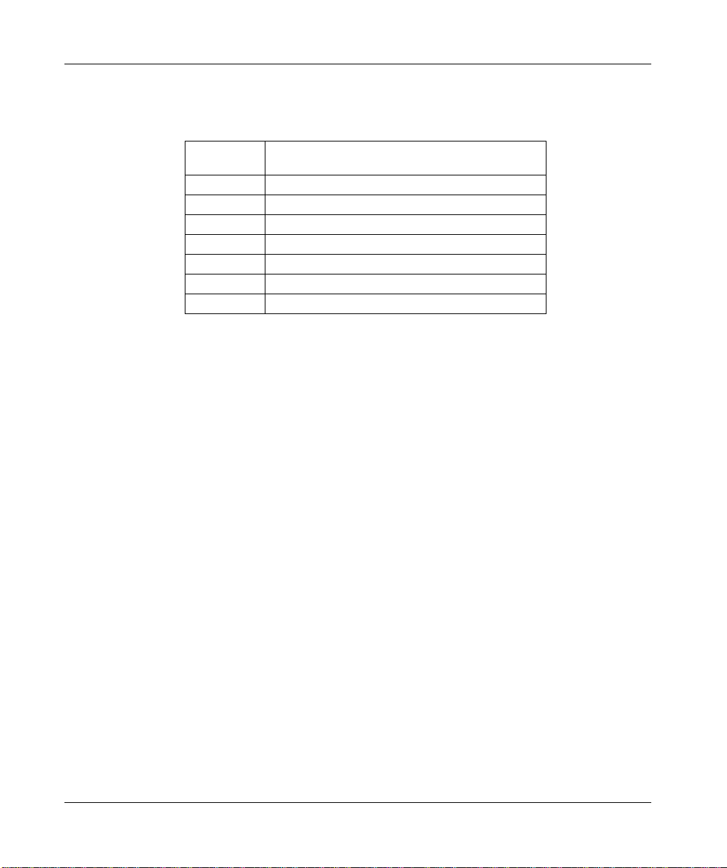
What’s in this Chapter
This chapter provides general information about this user guide and contains the
following topics:
Topic Page
About this user guide 2 Related system components and standards 4 Related documentation 5 Hazards, warnings, and guidelines 6 Standards and compliances 10 Conventions 12
1
Page 14
About this User Guide
Who Should Use this User Guide
How this User Guide Is Organized
This user guide is written for any qualified person at your site who is responsible for
installing (mounting and interconnecting), operating, testing and maintaining your
Lexium 17S SERCOS drive and the servo system equipment with which it
interfaces. In addition, the following precautions are advised:
l Transportation of the drive to, or from, an installation site should only be
performed by personnel knowledgeable in handling electrostatically sensiti ve
components.
l Commissioning of the equipment should only be performed by personnel
having extensive knowledge of, and experience with, electrical and drive
technologies.
You are expected to have some overall understanding of what your 17S SERCOS
drive does and how it will function in a high-performance, multi-axis motion control
system. Accordingly, be sure you read and understand the general information,
detailed descriptions and associated procedures presented in this manual, as well
as those provided in other relevant manuals, before installing your 17S. (See
Related System Components
later in this chapter.)
If you have questions, please consult your Schneider Electric customer
representative.
This manual is organized as follows.
Chapter/Appendix Description
Chapter 1
About this User Guide
Chapter 2
Lexium 17S Product Overview
Chapter 3
Mounting and Physical Dimensions
An introduction to this manual — who should use
this manual, how this manual is organized,
related publications, hazards and warnings.
General descriptions of the 17S SERCOS
drives, descriptions of components that are
supplied by Schneider in a typical 17S system,
and a block diagram for internal electronics.
Physical dimensions and information for
mounting the 17S SERCOS drive, optional
Regen resistor and (if required) optional servo
motor choke.
Continued on next page
2
Page 15

About this User Guide, continued
How this User
Guide Is
Organized,
continued
Chapter/Appendix Description
Chapter 4
Wiring and I/O
Chapter 5
System Initialization, Commissioning and Operation
Chapter 6
Troubleshooting
Appendix A
Specifications
Appendix B
Parts List
Appendix C
Cable Connection Wiring Diagrams
Appendix D
Servo Loop Diagrams
Appendix E
Optional External Regen Resistor Sizing
Wiring diagrams for the power connections and
wiring diagrams and descriptions for all signal
wiring connections — encoder, resolver, analog
input, discrete I/O, fiber-optic and serial
communications cable.
Detailed procedures and associated descriptions
on how to initialize, commission and operate a
typical 17S system.
Description of faults, probable causes and recommended corrective actions.
Specifications for the 17S SERCOS drives,
including general, electrical, signal, and power
specifications.
Part numbers related to the 17S SERCOS drive
system.
Procedures and associated diagrams that show
how to wire Sub-D and power cable connectors
as well as the serial communication cable used
with the drive.
Illustrations of several servo loops within the 17S SERCOS drive system.
Description and procedure for determining the
power dissipation requirement for the optional
external Regen resistor.
3
Page 16

Related System Components
SERCOS MultiAxis Motion
Control System
UniLink Commissioning Software for 17S
The 17S SERCOS drive is typically only one component in a larger, multi-axis
motion control system. A multi-axis system is comprised of one motion controller
and (depending on the controller) up to 32 drives. Each drive controls one servo
motor.
To configure your multi-axis system, you will be using the UniLink axis
commissioning software, which Schneider supplies.
UniLink allows you to configure and tune your 17S axis quickly and easily. With its
graphical user interfa ce and osci lloscop e tuning feat ures, UniL ink provides an easy
point-and-click me thod for confi guring moti on setup p arameters. U niLink mi nimizes
or eliminates cumbersom e programming tasks.
For complete information on UniLink, please see the UniLink online help.
4
Page 17
Related Documentation
Documents Related documentation that covers all these system components is illustrated
below.
You will need these:
UniLink
Online Help
(included
in software)
Depending on which SERCOS motion controller you have, you will also need there:
QUANTUM:
Quantum
SERCOS
Multi-axis Motion
Controller
Guide
MMF
Programmer’s
Kit
User Guide
840 USE 116 X
PREMIUM:
PREMIUM PLCs
Motion Control
SERCOS Module
TSX CSY 84
User Manual
TSXDM5740
If you have a BPH motor, you will also need this:
Lexium BPH
Series
Servo Motors
Motors Reference
Guide
* AMOMAN001U
* included in AM0 CSW 001V•00 (CDROM)
890 USE 119 00
PL7 JUNIOR/PRO
PREMIUM PLCs
Application
Motion Control
SERCOS Module
TSX CSY 84
TLXDS57PL740
5
Page 18
Hazards, Warnings and Guidelines
Hazards and Warnings
Read the followi ng precautions very carefully to ensure the safety of personnel at
your site. Failure to comply will result in death, serious injury or equipment damage.
DANGER!
ELECTRIC SHOCK HAZARDS
l During operation, keep al l covers and cabine t doors closed.
l Do not open the drives; depending on degree of enclosure protection, the
drives may have exposed components.
l Control and power connections on the drive may be energized even if the
motor is not rotating.
l Never attempt to disconnect the electrical connections to the drive with power
applied. Failure to comply may result in arcing at the contacts.
l Wait at least five minutes after disconnecting the drive from the mains supply
voltage before touching energized sections of the equipment (for example,
contacts) or disconnecting electrical connections. Capacitors can still have
dangerous voltages present up to five minutes after switching off the supply
voltages. To ensure safety, measure the voltage in the DC Link circuit and wait
until it has fallen below 40V before proceeding.
l Check to ensure all energized connecting elements are protected from
accidental contact. Lethal voltages up to 900V can be present. Never
disconnect any electrical connections to the drive with power applied;
capacitors can retain residual and dangerous voltage levels for up to five
minutes after switching off the supply power.
Failure to follow any one of these instructions will result in death, serious
injury or equipment damage.
Continued on next page
6
Page 19
Hazards, Warnings and Guidelines, continued
WARNING!
THERMAL HAZARD
During operation, the front panel of the drive, which is used as a heat sink, can
become hot and may reach temperatures above 80°C. Check (measure) the heat
sink temperature and wait until it has cooled below 40°C before touching it.
Failure to observe this precaution can result in severe injury.
WARNING!
OVERCURRENT, OVERLOAD AND OVERHEATING PROTECTION
Separate motor overcurrent, overload and overheating protection is required to be
provided in accordance wit h the Ca nad ian Elec tric al Code, Part 1 an d the National
Electrical Code.
Failure to observe this precaution can result in severe injury.
Continued on next page
7
Page 20
Hazards, Warnings and Guidelines, continued
CAUTION!
SAFETY INTERLOCKS
Schneider recommends the installation of a safety interlock with separate contacts
for each motor. Such a system should be hard w ire d wi th over–travel limit s w itc he s
and a suitable emergency stop switch. Any interruption of this circuit or fault
indication should:
l Open the motor contacts
l Shunt dynamic braking resistors across each motor, if they are present.
Failure to observe this precaution can result in equipment damage.
CAUTION!
ELECTROSTATIC COMPONENTS
The drives contain electrostatically sensitive components that may be damaged by
improper handling. Appropriately discharge yourself before touching the drive and
avoid contact with highly insulating materials (artificial fabrics, plastic film, and so
on). Place the drive on a conductive surface.
Failure to observe this precaution can result in equipment damage.
Continued on next page
8
Page 21

Hazards, Warnings and Guidelines, continued
Additional Safety Guidelines
Qualified Personnel
Read this documentation and adhere to the safety guidelines contained herein
before engaging in any activities involving the drives.
l Ens ure that al l wiri ng is in a ccorda nc e with the Nati ona l Ele ctr ical Cod e (NEC)
or its national equivalent (CSA, CENELEC, and so on), as well as in
accordance with all prevailing local codes.
l Exercise extreme caution when using instruments such as oscilloscopes, chart
recorders, or volt–ohm meters with equipment connected to line power.
l Handle the drives as prescribed herein. Incorrect handling can result in
personal injury or equipment damage.
l Adhere to the technical information on connection requirements identified on
the nameplate and specified in the documentation.
l The drives may only be operated in a closed switchgear cabinet with
appropriate compensation for ambient conditions (as defined in Appendix A).
Only properly qualified personnel having extensive knowledge in electrical and
drive technologies should install, commission and/or maintain the Lexium 17S
SERCOS drives.
9
Page 22

Standards and Compliances
European Directives and Standards
EC Directive Compliance
The Lexium 17S SERCOS drives are incorporated into an electrical plant and into
machinery for industrial use.
When the drives are b ui lt int o mac hines or a plant, do no t oper ate the d riv e until the
machine or plant fulfills the requirements of these European Standards:
l EC Directive on Machines 89/392/EEC
l EC Directive on EMC (89/336/EEC)
l EN 60204
l EN 292
In connection with the Low Voltage Directive 73/23/EEC, the associated standards
of the EN 50178 series in conjunction with EN 60439-1, EN 60146 and EN 60204
are applied to the drives.
The manufacturer of the mach ine or plant is responsible for meeting the
requirements of the EMC regulations.
Compliance with the EC Directive on EMC 89/336/EEC and the Low Voltage
Directive 73/23/EEC is mandatory for all drives used within the European
Community.
The Lexium 17S SERCOS drives were tested by an authorized testing laboratory
and determined to be in compliance with the directives identified above.
10
Continued on next page
Page 23

Standards and Compliances, continued
SERCOS Standard
UL and cUL Compliance
If you want to reference the internatio nal SERCO S communic ations st andard , get a
copy of:
International Standard IEC 1491,
Electrical Equipment of Industrial Machines –
Serial Data Link for Real-Time Communication between Controllers and Drives.
SERCOS is an industry standard term that refers to a special type of fiber–optic
communication protocol, as defined by the SERCOS Interface, Inc., promotion
society. (SERCOS® interface is a trade mark o f SERCO S Interf ace, I nc., pro motion
society.)
UL Listed (cUL Certified) drives (Underwriters Laboratories Inc.) comply with the
relevant American and Canadian standards (in this case, UL 840 and UL 508C).
This standard describes the minimum requirements for electrically operated power
conversion equipme nt (such as frequen cy con v erters and drive s) and is intended to
eliminate the risk of inj ury to personnel fro m electric sh ock or d amage to eq uipment
from fire. Conformance with the United States and Canadian standard is
determined by an indepe nde nt UL (cU L ) fire in spe ct or th roug h th e ty pe tes tin g and
regular checkups.
UL 508C
UL 508C describes the minimum requirements for electrically operated power
conversion equipme nt (such as frequen cy con v erters and drive s) and is intended to
eliminate the risk of fire caused by that equipment.
UL 840
UL 840 describes ai r and in sulat ion creep age spa cings f or electrical equipment and
printed circuit boards.
11
Page 24

Conventions
Acronyms and Abbreviations
The acronyms and abbreviations used in this manual are identified and defined in
the table below.
Acronym or
Abbreviation Description
CE European Community (EC) CLK Clock signal COM Serial communication interface for a PC-AT cUL Underwriters Laboratory (Canada) DIN German Institute for Norming Disk Magnetic storage (diskette, hard disk) EEPROM Electrically erasable programmable read only memory EMC Electromagnetic compatibility EMI Electromagnetic Interference EN European norm ESD Electrostatic discharge IEC International Electrotechnical Commission IGBT Insulated Gate Bipolar Transistor ISO International Standardization Organization LED Light Emitting Diode MB Megabyte MS-DOS Microsoft Disk Operating System for PC-AT PC-AT Personal computer in AT configuration PELV Protected extra low voltage PWM Pulse-width modulation RAM Random Access Memory (volatile) Regen Regen resistor RBext External Regen resistor RBint Internal Regen resistor RFI Radio Frequency Interference
12
Continued on next page
Page 25
Conventions, cont inued
Acronyms and
Abbreviations,
continued
Acronym or
Abbreviation Description
PLC Programmable Logic Controller SERCOS Serial Realtime Communication System SRAM Static RAM SSI Synchronous Serial Interface UL Underwriters Laboratory Vac Voltage, Alternating Current Vdc Voltage, Direct Current
13
Page 26

14
Page 27
Product Overview
2
At a Glance
Introduction This chapter contains a product o v erview of th e Le xium 17S series SERCOS driv es
and includes:
l Available drive models and related system components
l Feedback and performance information
l Power and signal electronics
l Software and axis configuration
What’s in this Chapter
This chapter contains the following topics:
Topic Page
The 17S series SERCOS drive family 16 Modicon Multi-Axis Motion SERCOS
Network Configuration
Overview of usability features 25
Overview of 17S internal electronics 27
Overview of system software 31
22
15
Page 28
The 17S Series SERCOS Drive Family
Introducing the 17S SERCOS Drive Family
Each member of the Lexium 17S series SERCOS drive family is comprised of a
three-phase brushless servo amplifier, power supply, high-performance digital
controller and SERCOS fiber optic interface all housed in a single enclosure.
Drives Available The 17S drives are available in five models which are correlated to different output
current levels as identified in the following table.
Output Current (Peak) 17S Drive
4.2 A MHDS1004N00
8.4 A MHDS1008N00
16.8 A MHDS1017N00 28 A MHDS1028N00 56 A MHDS1056N00
Implementing the Drives
The Lexium 17S SERCOS drives are intended for incorporation into electrical
equipment or ma ch ine ry and can on ly be commissioned as integr al com ponents of
those types of devices.
Applicable Servo Motor Ty pes
The Lexium 17 S SERCO S drives are i ntended to driv e BPH series brush less se rvo
motors.
16
Continued on next page
Page 29

The 17S Series SERCOS Drive Family, continued
Electrical Considerations
The Lexium 17S family of servo amplifiers is to be used on earthed three-phase
industrial mains supp ly networks (TN- system, TT-syste m with earthed neutral point,
not more than 5000 rms symmetrical amperes).
The Lexium drives are incompatible with the IT system because interference
suppression filter s are i nternal and c onnec ted to e arth. If the us er wa nts to c onnec t
Lexium drives to an IT system, he may:
l us e an insul ation sta r transformer in order to re-create a local TT or T N system .
This way allows the rest of the wiring to stay an IT system (only warning in case
of the first fault.)
l us e a special R esidual Curren t Circuit Break er (RCC B) that is ab le to work w ith
dc and high peak currents. This device detects unbalance of phases with
regard to earth.
Warning: When the first fault occurs, the RCCB has to switch off quickly power
of the drives. Set of the residu al curre nt v alu e mu st be c arefull y done and m ust
be started with the lowest available value (for exampl e: 30mA.)
Following equipm ent of Merlin Gerin can be used:
l Vigirex, model RH328AF (Reference: 50055)
l One of these magnetic cores:
- model TA, 30mm in internal diameter (Reference: 50437)
- model PA, 50mm in internal diameter (Reference: 50438)
- model IA, 80mm in internal diameter (Reference: 50439)
If the servo amplifiers are used in residential areas, or in business or commercial
premises, then additional filter measures must be implemented by the user.
The Lexium 17S family of servo amplifiers is only intended to drive specific
brushless synchronous servomotors from th e Lexium BPH series, with closed-loo p
control of torque, speed and/or position. The dielectric withstand voltage of the
motors must be at least as hight as the DC-link voltage of the servo amplifier.
Use only copper wire. Wire siz e may be determinated from EN 60204 (or table 310-
16 of the NEC 60°C or 75°C column for AWG size).
We only guarantee the conformance of the servo amplifiers with the standards for
industrial areas, if the co mp onents (motors, cables, amplifi ers etc ) are d elivered by
Schneider Automa tio n.
Continued on next page
17
Page 30
The 17S Series SERCOS Drive Family, continued
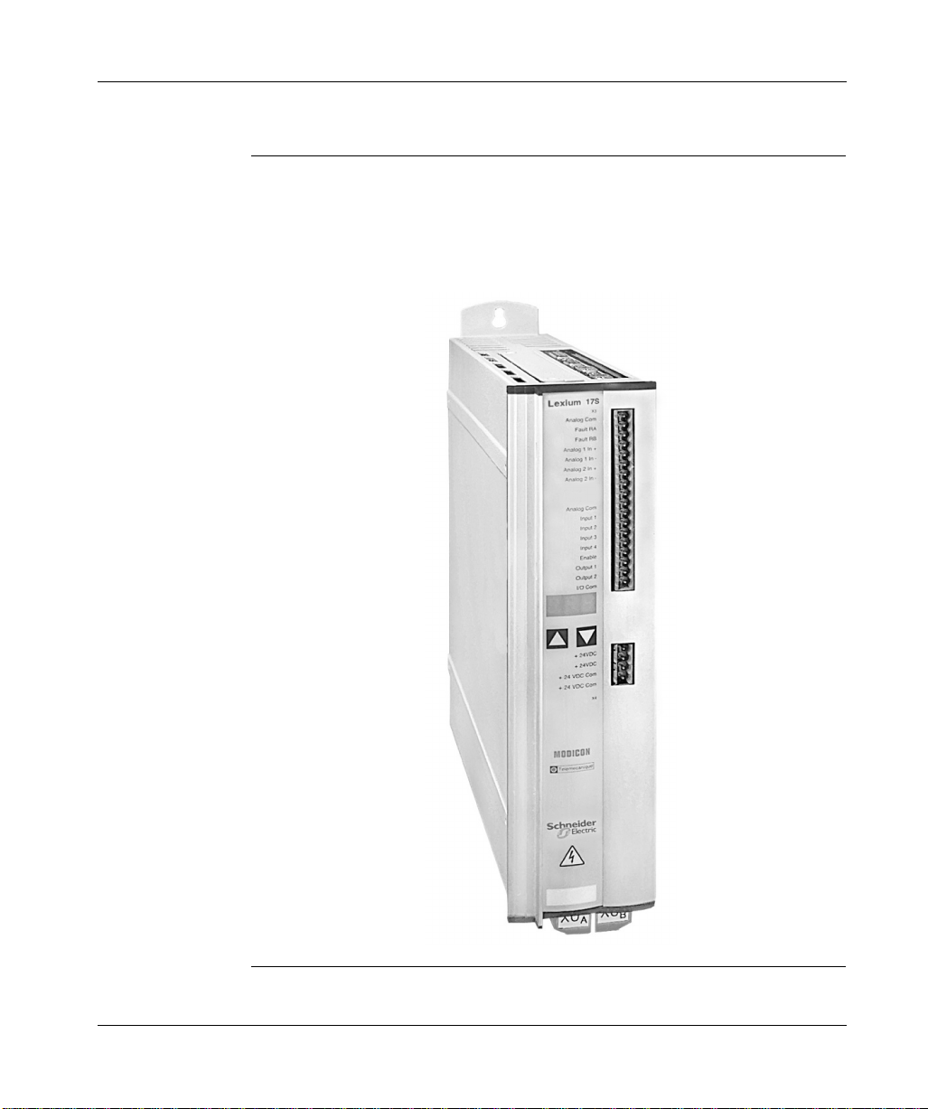
17S Drive Family Portrait
The following photograph shows a representative member of the 17S drive family.
The complete family consists of five models partitioned into two physical sizes.
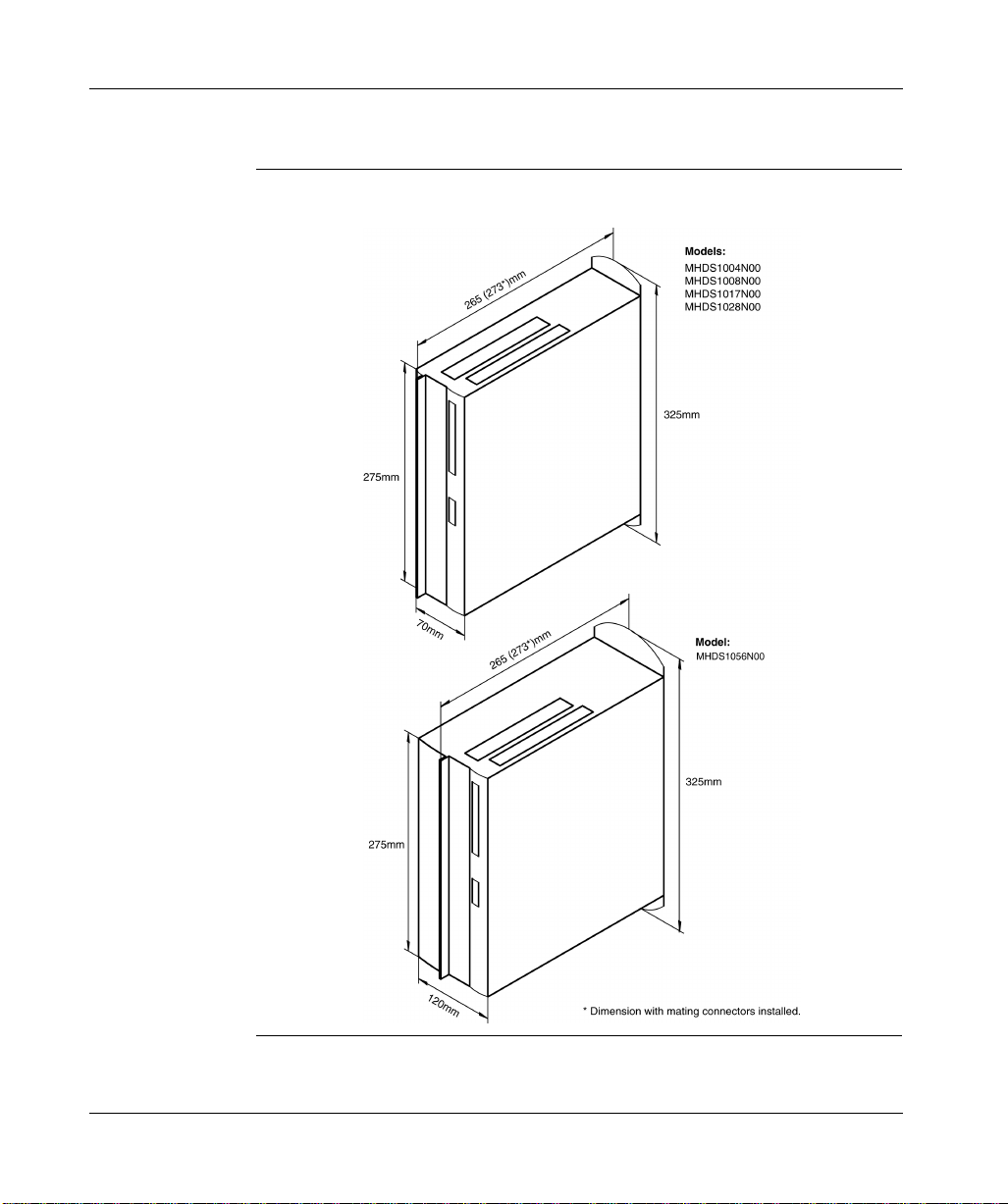
Models MHDS1004N00, MHDS1008N00, MHDS1017N00 and MHDS1028N00
have dimensionally identical physical housings while Model MHDS1056N00 has a
wider housing. (See Chapter 3 for detailed dimensional information.)
18
Continued on next page
Page 31

The 17S Series SERCOS Drive Family, continued
17S Drives Front View
The following photograph shows a typical 17S front view with legends and labels.
Continued on next page
19
Page 32
The 17S Series SERCOS Drive Family, continued
Equipment Supplied
Equipment Available
Each 17S SERCOS drive includes the following hardware.
l Mating connectors X3, X4, X0
, X0B, X7 and X8
A
l Read me first
Note: The mating Sub-D connectors and servo motor connector X9 are supplied
with the appropriate cabl e.
The following items are optionally available to you from Schneider for use with the
17S SERCOS drives:
l Lexium BPH series brushless servo motors
l Servo motor power and feedback cables
Note: Power and feedback cables are available in lengths from 5...75 m and are
supplied by Schneider with the connector for the servo motor attached to the cable
and with the connector for the drive unassembled and unattached to the cable. The
10 m length cable is su pplied (from stoc k) b y Schneider with connectors att ached to
each end of the cable.
l Optional servo motor choke (for motor power cable lengths exceeding 25m)
l Optional external Regen resistor
l Serial communications cable (between drive and PC)
l SERCOS fiber optic cables in lengths of 0.3...38 m
20
Continued on next page
Page 33
The 17S Series SERCOS Drive Family, continued
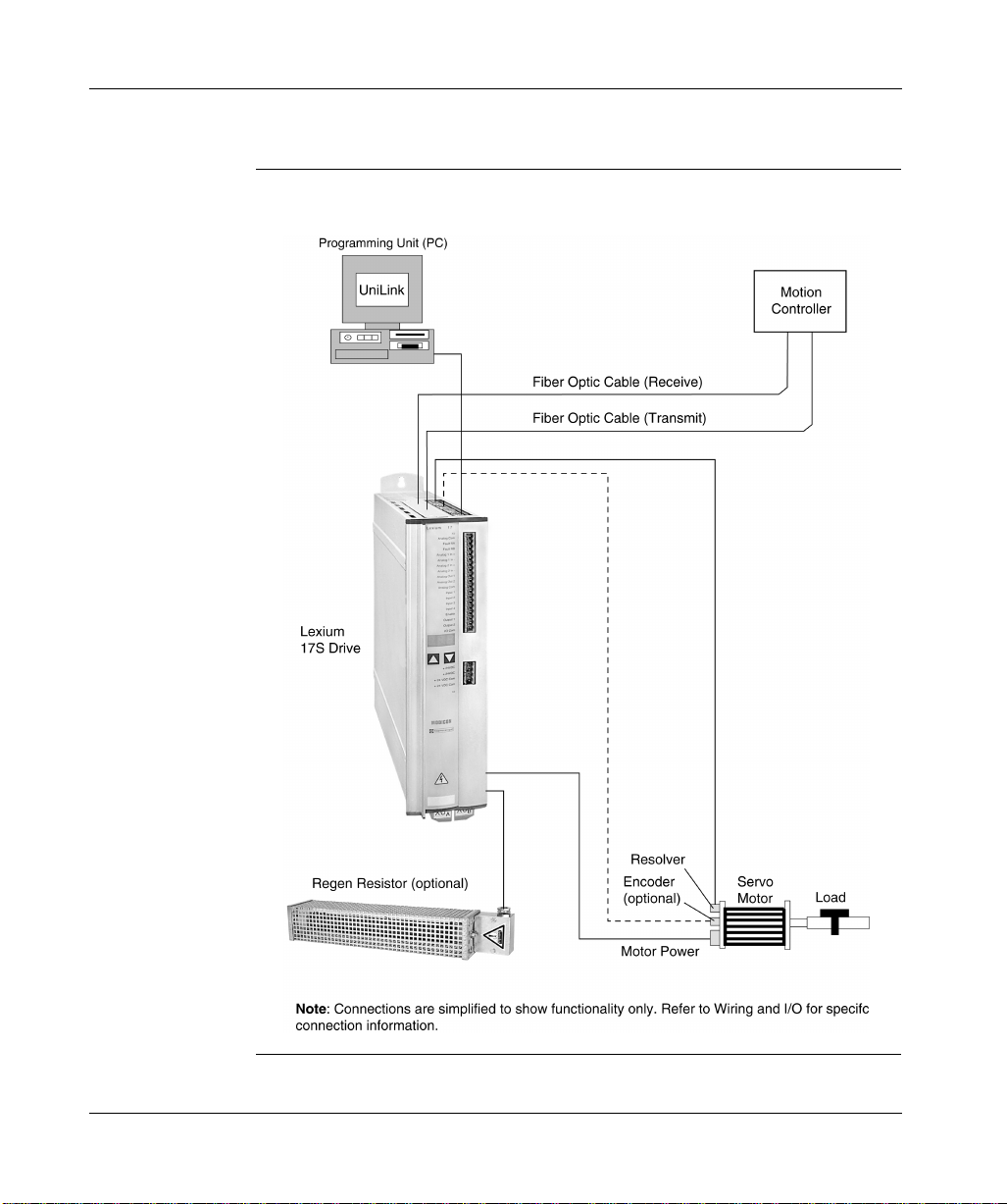
17S System Configuration Diagram
The following illustration shows a typical 17S system configuration.
21
Page 34

Modicon Multi-Axis Motion SERCOS Network Configuration
Overview The 17S drive is typica lly c onfigu red in a SERC OS net work con tai ning m any a xes.
A Schneider multi–axis motion controller configured with a SERCOS processor
board transmits motion instructions to all the 17S drives that are properly
configured in the fiber–optic loop.
Which Motion Controllers run a SERCOS Network
SERCOS FiberOptic Transmit
and Receive
Connectors
The controller that runs a network of many SERCOS axes is a Modicon Quantum
Automation Series SERCOS multi–axis motion controller (part number
141MMS42501) or TSX Premium CSY motion controller. Each controller supports
one independent SERCOS network ring. Each ring can contain up to 8 axes (8
drives and their motors). The 17S may also be configured with a compatible non–
Modicon SERCOS controller. Schneider also offers a 32-axis motion controller
(part number 141MMS53502).
Each 17S drive has two SERCOS–compliant SMA type fiber–optic connectors:
l TX (transmit)
l RX (receive)
Through a SERCOS–compliant, fiber–optic cable, the RX connector receives the
controller’s command instructions (as well as actual motion information from the
previous axes) from the previous drive in the ring. Likewise, the TX connector
transmits the controller’s command instructions (along with actual motion
information from the axes) to the next drive in the ring. The SERCOS multi–axis
motion controller also has a fiber–opti c transmitt er (TX) connector and a fiber–optic
receiver (RX) connector. The transmitter sends command instructions
commanded motio n
(
real feedback (
Transmission flows in one direction, with typical cycle times of 2ms to 4ms,
depending on the number or drives, volume of data, and data rate.
) to all the 17S axes in the ne tw ork ring. The receiver accepts
actual motion information
) from all the axes in the ring.
22
Continued on next page
Page 35
Modicon Multi-Axis Motion SERCOS Network Configuration, continued
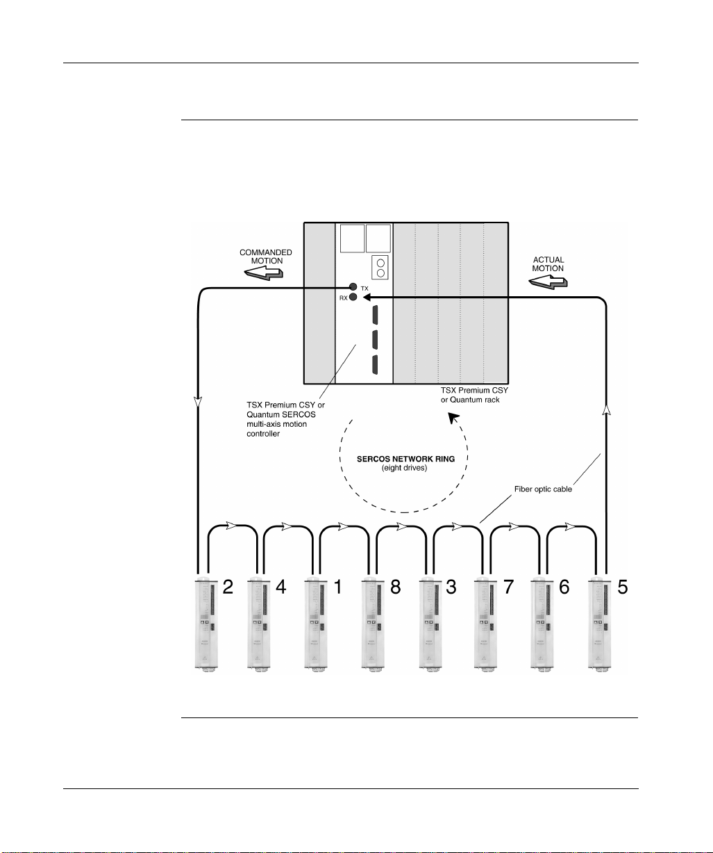
Example of a Typical SERCOS Network Ring Configuration
The following figure shows a typical configuration of 17S SERCOS axes with
arbitrary node addresses receiving and transmitting instructions from a multi–axis
motion controller.
Continued on next page
23
Page 36

Modicon Multi-Axis Motion SERCOS Network Configuration, continued
Example of a
Typical SERCOS
Network Ring
Configuration,
continued
Benefits of Fiber-Optic Communication
Two Types of Fiber-Optic Communication
As shown in the figure, the ring ha s eight ax es. Thes e axes ne ed not be c onfigured
sequentially. Any axis in the ring can be identified as axis 1, axis 2, axis 3, and so
on. However, each address within a ring must be unique.
The SERCOS multi–axis motion controller coordinates the motion activities of the
various SERCOS axes on the network ring. Fiber optic communication allows
efficient synchronization of multiple axes through flexible SERCOS networking
rather than through a constraining backplane bus configuration. SERCOS
networking allows you to place each drive close to its motor. This reduces and
eliminates cumbersome wiring from the motor to the controller. The fiber–optic
SERCOS protocol provides com plete electrical is olation between drive axes as w ell
as between each drive axis and the motion controller. This eliminates wiring
difficulties, such as ground loops, which are present in hard–wired systems.
The SERCOS protocol allows two types of communication simultaneously
throughout the network ring:
l Constant real–time data updates
l Slower intermittent messaging
This flexibility allows the communication to serve many different types of motion
applications.
24
Note: For more information on fiber optic connections and signal wiring, see
Chapter 4 and Appendix C.
Page 37

Overview of Usability Features
Digital Control The 17S drive provides complete digital control of a brushless servo system. This
includes:
l A digital field-oriented current controller operating at an update rate of 62.5 µs
l A fully programmable digital PI-type speed controller operating at an update
rate of 250 µs
l Ful l digita l e v aluation of motor position f eedbac k (primary feed back ) from e ither
a standard two-poles resolver or a high precision Sin-Cos type encoder
(hiperface).
Continued on next page
25
Page 38

Overview of Usability Features, continued
Usability Enhancements
The following features are incorporated into the 17S drive to facilitate the set-up
and operation of the servo system:
l Two analog +/-10 V inputs can be programmed for a multitude of functions
depending upon the application. Both inputs incorporate automatic offset
compensation, dead-band limitation and slew-rate limitation.
l Four fully programmable 24 V discrete inputs; two of which are typically defined
as hardware limit switches.
l Two fully programmable 24 V outputs and a separate 24 V brake output
capable of driving a maximum of 2 Amps.
l An integrated and fully isolated RS-232 connection for communication with a
PC; used to set configuration parameters and tune the system with the Unilink
configuration software.
l A separate 24V bias supply input which may be connected through a UPS to
preserve system data in the event of an interruption in the AC mains supply.
26
Page 39

Overview of 17S Internal Electronics
17S Internal Electronics Block Diagram
The following block diagram illustrates the 17S internal electronics and depicts
internal interfaces for power, signal I/O, and communication.
ROD SSI
2
Analog1 in+
Analog1 in-
Analog2 in+
Analog2 in-
ROD
SSI
+Rb ext
+Rb int
-Rb
X9
X2
X1
X9
Continued on next page
27
Page 40

Overview of 17S Internal Electronics, continued
General Characteristics
The Lexium 17S SERCOS drives are available in five peak output current ratings
(4.2, 8.4, 16.8, 28 and 5 6 A) th at are partitioned into two grou ps ba sed o n the width
of the package; the 70 mm drives are rated to handle currents up to 28 A and the
120 mm wide drive i s ra ted to handl e currents up to 56 A. All Le x ium d rive s opera te
with an input voltage whic h may range from 208 V -10% 60 Hz, 230 V -10%
50 Hz through 480 V +10% 50-60 Hz.
Each drive pr ovides:
l Direct shield connection points
l Two analog setpoint inputs
l Integrated and electrically isolated RS-232 communications
Primary Power A single phase input supply may be used for commissioning and set-up and for
continuous operation with various smaller drive/motor combinations. See the
Lexium 17/ BPH motor torque speed curves for details.
Fusing (e.g. fuse cut-out) is provided by the user.
Bias Power The 17S drive requires 24 Vdc bias power from an external, electrically isolated
supply.
EMI Suppression EMI suppression for the 17S drives is integrally provided by filters on both the
primary power (EN550011, Class A, Group 1) input as well as on the 24 Vdc bias
supply (Class A) input.
Continued on next page
28
Page 41

Overview of 17S Internal Electronics, continued
Internal Power Section
DC Link Capacitor Reconditioning
Integrated Safe Electrical Separation
The Internal power section of the 17S drive includes the following:
l Power input: A rectifier bridge directly connected to the three-phase earthed
supply system, integral power input filter and inrush current limiting circuit.
l Motor po w er out put: PWM curren t-controlle d vo ltage so urce IGBT-inv e rter with
isolated current measurement
l Regen circuit: Dynamic distribution of Regen power between several drives on
the same DC Link circuit. An internal Regen resistor is standard; optional
external Regen resistors are available as required by your application.
l DC Link voltage: 300...700 Vdc, nominal (900 Vdc, intermittent) and can be
operated in parallel.
If the servo drive has been stored for longer than one year, then the DC Link
capacitors will have to be reconditionned as follows:
Step Action
1 Ensure that all electrical connections to the drive are disconnected.
2 Provide 230 Vac, single-phase power to connector XO
servo drive for about 30 minutes to recondition the capacitors.
(terminals L1/L2) on the
A
The 17S drive ensures safe electrical separation (in accordance with EN 50178)
between the power input/motor connections and the signal el ectronics through the
use of appropriate insul ati on-c r ee pag e di stances and electrical isolation. The driv e
also provides soft-s tart characteristic s, o v ervoltage an d ov ertemperat ure detecti on,
short-circuit protection and input phase-failure monitoring. When using BPH series
servo motors in conjunction with Schneider’s pre-assembled cables, the drive also
monitors the servo motor for overtemperature.
Keypad The operation of the keypad on the front panel of the 17S drive is described in
System Operation. The se two keys can be used (as an al ternative to using the PC)
to enter the SERCOS address fo r the drive
29
Page 42

LED Display and Discrete Indicators
A three-character LED display on the front of the 17S drive indicates drive status
after the 24 Vdc bias supply is turned on. If applicable during operation, error and/
or warning codes are displayed. In addition, three individual LED indicators (one
red and two green) on the SERCOS communication card (at the top of the drive)
are used to indicate the status of that communications.
Continued on next page
30
Page 43

Overview of System Software
Setup Configuration software is used for setting up and storing the operating parameters
for the Le x ium 17S s eries d rives. The drive is commissioned wi th th e as si stance of
the UniLink software and, during this process, the drive can be controlled directly
through this software.
Setting Parameters
You must adapt the SERCOS driv es to the requi remen ts of y our inst all ation. T his is
usually accomplish ed by co nnecting a PC (progra mming unit) t o the drive’s RS-232
serial interface th en running the Schnei der-sup plied U niLi nk con figur ation so ftw are .
The UniLink software and the associated documentation are provided on a CDROM. Use the UniLink software to alter parameters; you can instantly observe the
effect on t he drive because there is a contin uous (onl ine) c onnec tion to the driv e . In
addition, actual val ues are si multan eously rec eived from the drive an d displa y ed on
the PC monitor.
Default Settings Motor-specific default settings for all the reasonable combinations of drive and
servo motor are incorporated i nto the driv e’ s firmware. In most appl ications , y ou will
be able to use these default values to get your drive running without any problems.
(Refer to the UniLink online help for additional information on default values.)
Continued on next page
31
Page 44

Overview of System Software, continued
UniLink Commissioning Software
The minimum PC system requirements needed for the UniLink commissioning
software ar e specified in the following table:
Item Minimum Requirement
Operating System Windows 95
Hardware:
Processor
Graphics adapter
RAM
Hard drive space
Communications
Windows 98
486 or higher VGA 8 Mbytes 5 Mbytes available One RS-232 serial port
32
Page 45

At a Glance
Mounting and Physical Dimensions
3
What’s in this Chapter
This chapter provides information on the mounting requirements for, and physical
dimensions of, the Lexium 17S series SERCOS drives and includes the following
topics:
Topic Page
Installation safety precautions 34 Installation considerations 36 Drive mounting and physical dimensions 37 Optional external Regen resistor mounting and
dimensions
Optional choke mounting and dimensions 40
39
33
Page 46

Installation Safety Precautions
CAUTION!
MECHANICAL STRESS
Protect the drive from physical impact during transport and handling. In particular,
do not deform an y exterior surfaces; doing so may damage internal components or
alter critical insulation distances.
Failure to observe this precaution can result in injury or equipment damage.
CAUTION!
ELECTRICAL STRESS
At the installation site, ensure the maximum permissible rated voltage at the Mains
and bias input connectors on the drive are not exceeded. (See EN 60204-1,
Section 4.3.1.) Excessive voltages on these terminals can result in destruction of
the Regen circuit and/or the drive’s electronics.
Failure to observe this precaution can result in injury or equipment damage.
34
CAUTION!
ELECTRICAL CONNECTIONS
Never disconnect the electrical connections to the SERCOS drive while power is
applied.
Failure to observe this precaution can result in injury or equipment damage.
Continued on next page
Page 47

Installation Safety Precautions, continued
CAUTION!
CONTAMINATION AND THERMAL HAZARD
Ensure the 17S drive is mounted within an appropriately vented and closed
switchgear cabinet that is free of conductive and corrosive contaminants. Ensure
the ventilat ion clearanc es above and below the drive conform to requirements.
(Refer to Chapter 3 for additional information.)
Failure to observe this precaution can result in injury or equipment damage.
DANGER!
ELECTRIC SHOCK HAZARD
Residual voltages on the DC link capacitors can remain at dangerous levels for up
to five minutes after switching off the mains supply voltage. Therefore, measure the
voltage on the DC Link (+DC/-DC) and wait until the voltage has fallen below 40 V.
Control and power connections can still be energized, even when the motor is not
rotating.
Failure to observe these instructions will result in death or serious injury.
35
Page 48

Installation Considerations
Power Supply Overcurrent Protection
Earth Connections
Cable Separation Route power and control (signal) cables separately. Schneider recommends a
Air Flow Ensure that there is an adequate flow of coo l, filtered air into the bottom of the
You are responsible for providing overcurre nt p rote ction (via circuit breakers and/or
fuses) for the Vac mains supply and the 24 Vdc bias supply that are connected to
the drive.
Ensure the drive and associated servo motor are properly connected to earth.
separatio n of at least 20 cm. This degree of separation improves the performance
of the system. If a servo motor power cable includes wires for brake control, those
wires have a se parate shield which must be connected to earth at both en ds of the
cable.
switchgear cabinet containing the drive.
36
Page 49
Drive Mounting and Physical Dimensions
17S Height, Width and Depth Dimensions
The following diagram sh ow s hei ght , w id t h an d depth dimensions for the 17S drive.
Continued on next page
37
Page 50

Drive Mounting and Physical Dimensions, continued
17S Drive and Mounting Area Dimensions
The following diagram shows depth dimensions and mounting area requirements
for the 17S drive.
38
Page 51
Optional External Regen Resistor Mounting and Physical Dimensions
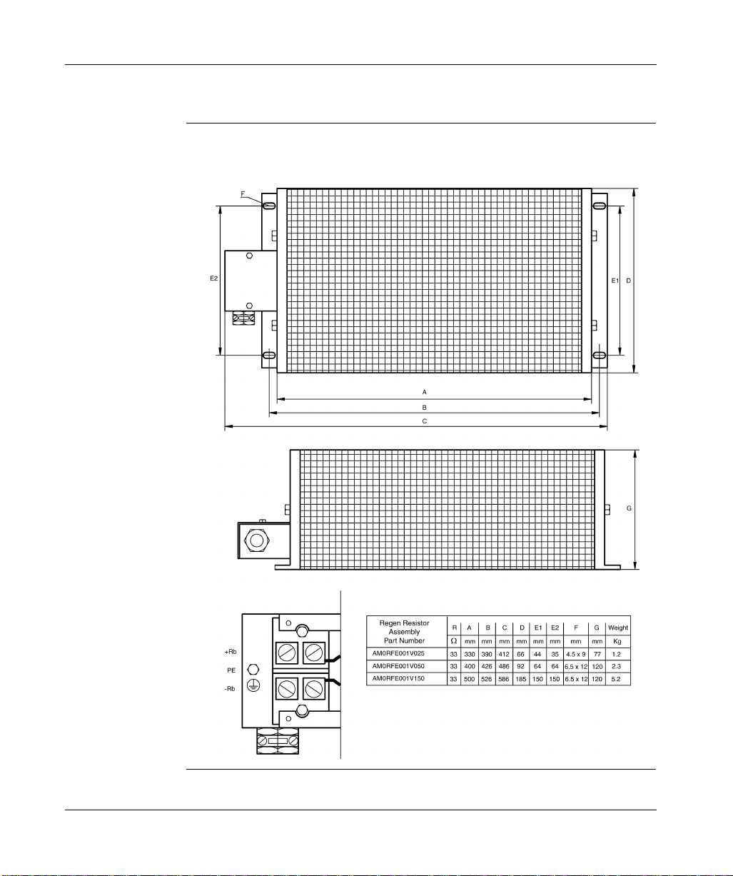
Optional External Regen Resistor Assembly Dimensions
The following diagram shows the dimensions for all three optional external Regen
resistor assemblies.
39
Page 52
Optional Motor Choke Mounting and Dimensions
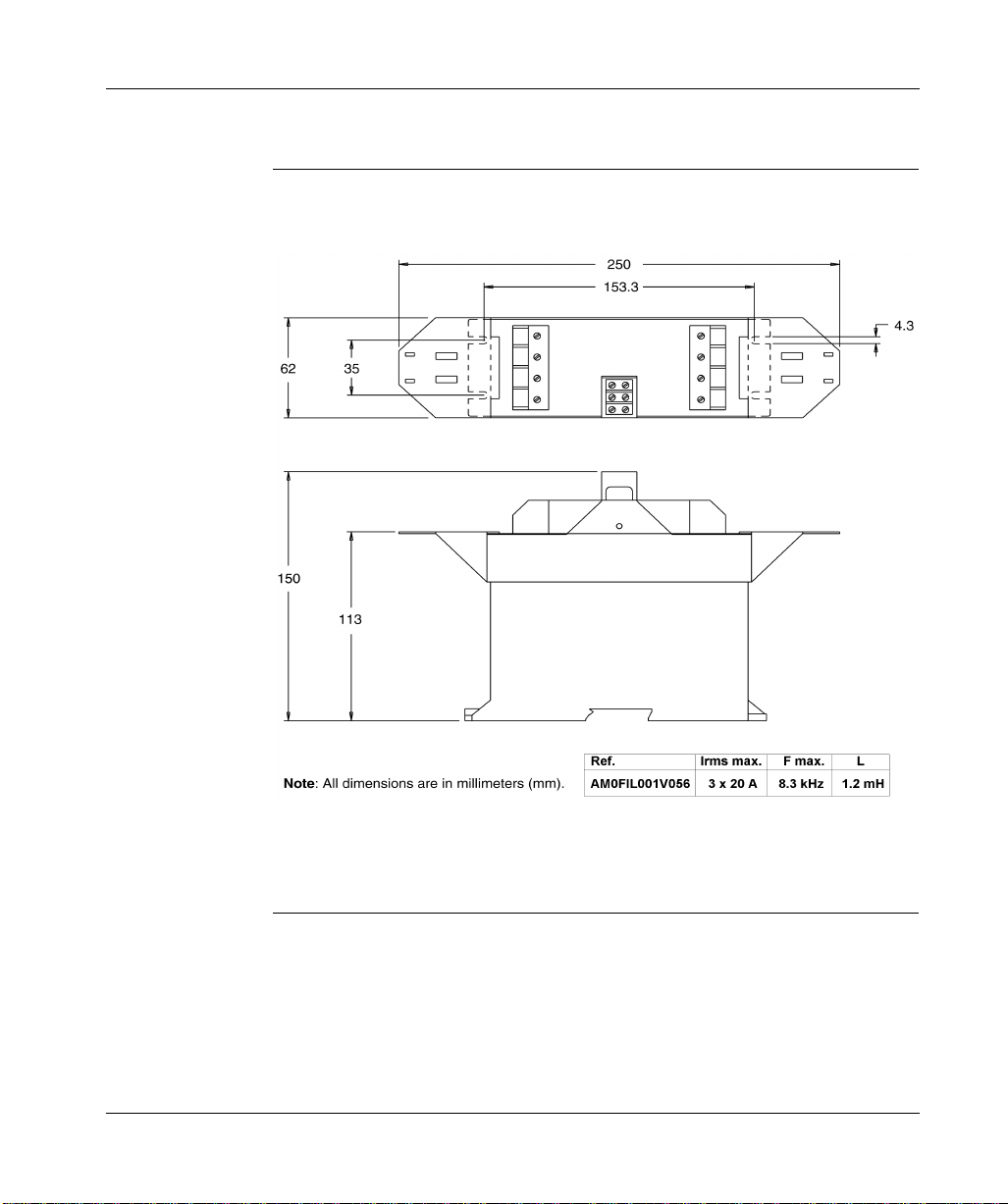
Optional Motor Choke Assembl y Dimensions
The following diagram shows the dimensions for the motor choke assembly
40
Page 53

Wiring and I/O
4
At a Glance
Introduction This chapter describes an d illu str ates all po w er wiring c onnec tions , a ll sig nal wiring
connections, and I/O wiring connections on the 17S drive. Power and signal wiring
connections are:
l AC mains power through a four-position, plug-in, terminal block connector
l Bias power through four-position, plug-in, terminal block connector
l Serial power connections among multiple drives
l Servo motor power through a six-position, plug-in, terminal block connector
l Optional Regen power resistor through a four-position, plug-i n, terminal
block connector
l Reso lve r feedb ack input through a nine-pin, plug-in, Sub-D connector
l Encoder feedback input through a 15-pin, plug-in, Sub-D connector
l Auxiliary encoder interface through a nine-pin, plug-in, Sub-D connector
l Fiber optic Interface through two SMA connectors
l Analog in and digital I/O through an 18-position, plug-in terminal block
connector
l Serial communications interface through a nine-pin, plug-in, Sub-D
connector
Continued on next page
41
Page 54
At a Glance, continued
What’s in this Chapter
This chapter contains the following topics.
Topic Page
Wiring and I/O initial considerations 43 Wiring overview 44 Cable shield connections 47 Power wiring 49 Signal wiring 57 Analog input connections 63 Fault Relay and Digital I/O connections 64 Serial communications connections 66
42
Page 55

Wiring and I/O Initial Considerations
Initial Considerations
Some descriptions and illustrations contained in this chapter are provided as
examples. Actual implementation depends on the application of the equipment;
thus, appropriate variations are allowed provided they neither violate any safety
precautions nor jeopardize the integrity of the equipment.
DANGER!
ELECTRIC SHOCK HAZARD
Before you wire and connect cables, ensure the mains power supply, the 24 Vdc
bias power supply and the power supplies to any other connected equipment, are
OFF. Ensure any cabinet to be accessed is first electrically disconnected, secured
with a lock-out and tagged with warning signs.
Failure to observe these safety instructions will result in death or serious
injury.
Grounding Ensure the drive mounting plate, SERCOS motor housing and Analog Com for the
controls are connected to common panel earth ground point.
Continued on next page
43
Page 56

Wiring Overview
Overview of 17S Wiring Connections
The following diagram shows the wiring connections for the 17S drive.
CAUTION:
Do not connect a Modbus serial port to the X6 connector!
Pin1 carries +8 Vdc which would be shorted out by a Modbus cable.
Instead, use a standard 3-core null-modem cable (not a null-modem link cable) with only
pins 2, 3 and 5 wired.
Failure to observe this precaution can result in equipment damage.
44
Note: The connectors described above appear in many wirin g diagrams throughou t
the remainder of this document and are identified in those diagrams by their
alphanumeric designations only (for example, X4); the term
connector
is excluded.
Page 57
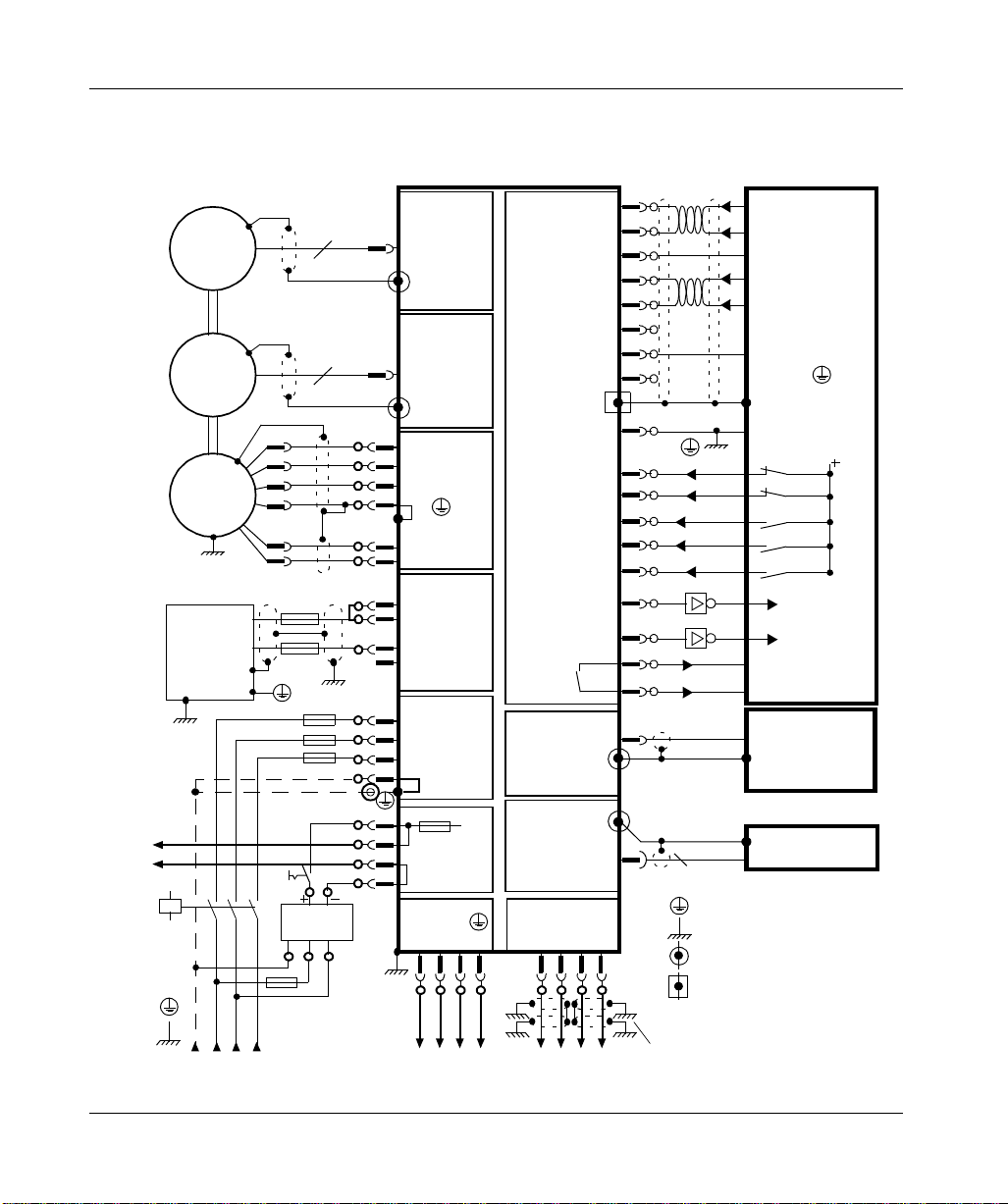
Connection diagram for Lexium 17S
Reference Safety Instructions
and Use As Directed!
Sine-Cosine
Encoder
Resolver
U2
V2
M
Remove jumper if external
regen resistor is connected
Regeneration
resistor
Master
contactor
PEL1 L2 L3
W
PE
B+
B-
thermal control
included
thermal control
included
F
B1
FB2
FN
FN
FN
supply unit
24V DC
FH
+ +/-10V speed
setpoint1
referenced to GND
GND
+ +/-10V speed
setpoint2
referenced to GND
GND
GND
I/O-GND
+24V referenced
to 0V/GND
Digital1
Digital2
Safety
circuit
encoderevaluation,
slave/master
amplifier
COM1/COM2
3
PE-connection (protective earth)
earth connection (panel)
shield connection via plug
shield connection at the front panel
Input 3
Input 4
Input 1
Input 2
Enable
ROD
SSI
Ma./SI.
PC
4
5
1
6
7
8
10
9
18
13
14
11
12
15
16
17
2
3
shielding if cable
is longer than 20cm
X1
15
8
high
resolution
single /
multiturn
X2
Resolver
6
U
5
V
4
W
3
P
2
Brake+
1
Brake-
2
+RBint
1
-RB
3
+R
4
n.c.
1
L1
2
L2
3
L3
4
1
2
+24 Vdc
3
24 Vdc Com
4
L1 L2 L3 PE
1234 1234
X9
X8
Bext
X0A
PE
X4
X0B
to other amplifiers
Analog 1 in +
Analog 1 in -
Analog Com
Analog 2 in +
Analog 2 in -
Reserved
Analog Com
Reserved
X3
I/O Com
Output 1
Output 2
Fault RA
Fault RB
X5
X6
X7
DC+ DC+DC- DC-
45
Page 58

Pin assignments for LEXIUM 17 S
X2 RESOLVERX5 ROD/SSIX6 PC X1 ENCODER
1 Reserved
Analog Com 1
Fault Ra 2
Fault Rb 3
Analog 1 In+ 4
Analog 1 In- 5
Analog 2 In+ 6
Analog 2 In- 7
Reserved 8
Reserved 9
Analog Com 10
Input 1 11
Input 2 12
Input 3 13
Input 4 14
Enable 15
Output 1 16
Output 2 17
I/O Com 18
+24Vdc 1
+24Vdc 2
+24Vdc Com 3
+24Vdc Com 4
2 RxD
3 TxD
4 N.C.
5 PGND
7
8
Reserved 6
X3
X4
Reserved 9
1 Pcom
2 M+
B+ (DATA) 6
3 M-
B- (/DATA) 7
4 A- (CLK)
5 A+ (/CLK)
N.C. 9
Reserved 8
B
0
X
5 R1
4 S2
3 S321 Shield
S4 8
R2 9
V
S1 7
V 6
V
8 Clock7 6 N.C.
14
V
Clock 15
5 DATA(+485)
4 Up (8V)
3 B+ (COS)
0V SENSE 10
Up SENSE 12
DATA (-485) 13
B- (REFCOS) 11
2 0V(GND)
1 A+ (SIN)
A- (REFSIN) 9
View: looking at the
face of the built-in
connectors
e
ak
br
/
or
ot
m
9
X
e+
e-
ak
N
E
G
E
R
8
T
X
X
.
E
c
B
nt
i
n.
R
B
+
4
R
+
3
RB
-
2
E
P
1
L3
4
2
L
3
L1
2
1
A
0
X
1
C
D
7
X
4
3
E
2
L3
2
L
L1
r
ak
B
r
B
1
t
ui
c
r
i
c
-
4
3
C
2
C
1
D
C
+
D
C
-
D
+
P
2
U
2
2
V
6
W
5
E
P
4
3
2
Coding
D
-
46
Continued on next page
Page 59

Cable Shield Connections
Connecting Cable Shields to the Front Pa nel
The following procedure and associated diagram describe how to connect cable
shields to the front panel of the 17S drive:
Step Action
Remove a length of the cable’ s outer covering and braided shield sufficient to
1
expose the required length of wires.
Secure the exposed wires with a cable tie.
2
Remove approximately 30 mm of the cable’s outer covering while ensuring the
3
braided shield is not damaged during the process.
At the front panel of the drive, insert a cable tie into a slot in the shielding rail.
4
Use the previously inserted cable tie to secure the exposed braided shield of
5
the cable firmly against the shielding rail.
Continued on next page
47
Page 60

Cable Shield Connections, continued
Cable Shield Connection Diagram
The following diagram shows the cable shield connections at the front of the 17S
drive.
48
Page 61

Power Wiring
AC Mains Power Supply Connection
Bias Supply Connection
The following diagram shows the connections for the AC mains power supply input
to the 17S drive.
*
*3 x 230 V +10% max. with a BPH055 Servo motor
The following diagram shows the connections for the bias power supply input to the
17S drive.
Continued on next page
49
Page 62

Power Wiring, continued
Serial Power Connections
The following diagram shows the serial connections for the AC mains and bias
power among multiple 17S drives.
AC supply
Lexium 17S
X4
+24
~
=
L1
L2
L3
+24
COM
COM
X0AX7X0B
L1
L2
L3
PE
+DC
-DC
+DC
-DC
PE
L1
L2
L3
Lexium 17S
X4
+24
+24
COM
COM
X0AX7X0B
L1
L2
L3
PE
+DC
-DC
+DC
-DC
PE
L1
L2
L3
Lexium 17S
X4
+24
+24
COM
COM
X0AX7X0B
L1
L2
L3
PE
+DC
-DC
+DC
-DC
L1
L2
L3
PE
To
Next
Drive
DC supply
NCNC
Lexium 17S
X4
+24
+24
COM
COM
X0AX7X0B
L1
L2
L3
PE
+DC
-DC
+DC
-DC
PE
L1
L2
L3
NC
To
Next
Drive
POWER
SUPPLY
+DC
-DC
24 Vdc
Power Supply
1
2
Fuse
Max fuse: 20 A
1
schielded if length > 20 cm
2
Lexium 17S
X4
+24
+24
COM
COM
X0AX7X0B
L1
L2
L3
PE
+DC
-DC
+DC
-DC
PE
L1
L2
L3
50
Notes: -Inrush current must be limited to 20 A between power supply and drives.
- Drives have to be configured (see Unilink commands) to suppress faults.
Continued on next page
Page 63

Power Wiring, continued
Optional External Regen Resistor Connection
Regen Circuit Functional Description
The follo win g dia gra m sh ows the conne ctions betw ee n the optio nal external Regen
resistor and the 17S drive. The drive is shipped with a jumper installed on
connector X8, terminals RB and R
. If you are going to use an optional external
Bint
Regen resistor, then remove the jumper to disconnect (and thus disable) the
internal Regen resistor.
Fusing of the two lines to external Regen Resistor is mandatory.
Use high voltage AC/DC and fast fuses.
During braking, energy from the servo motor is returned to the driv e an d co nverted
into heat in the Regen resistor. Operation of the Regen resistor is controlled by the
Regen circuit using thresholds that are adjusted to the main supply voltage that is
configured in the UniLink software. The following is an abbreviated functional
description of the Regen circuit operation.
l Ind ividual drive (not coupled through the DC Link circu it) - The circuit sta rts to
respond at a DC L ink voltage of 400V, 720V or 840V (depending on the supply
voltage). If the energy fed back from the servo motor is higher than the preset
Regen power, then the drive issues a "Regen power exceeded" signal and the
Regen circuit will be switched off. Upon the next i nternal check of the DC Link
voltage, an overvoltage will be detected, the fault relay contact will be opened
and the drive will be switched off with the error message "Overvoltage".
l Mu ltipl e driv es (coupled through the DC Link circu it) - In thi s c as e , the R ege n
energy is distributed equally among all the drives.
Continued on next page
51
Page 64

Power Wiring, continued
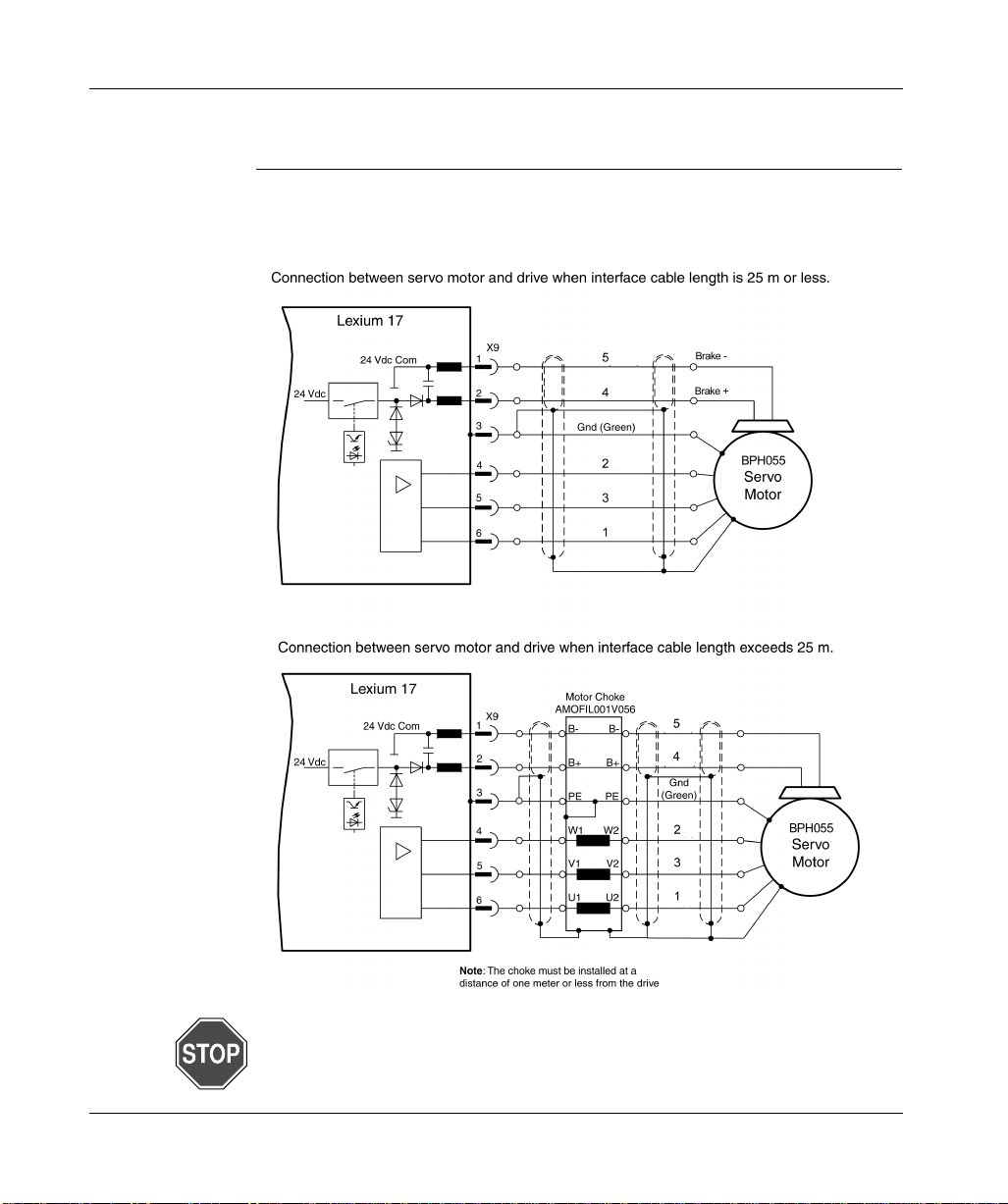
Lexium BPH Servo Motor Connection (excluded BPH055)
The following diagrams show the connections between a servo motor (excluded
BPH055) and the 17S drive. When the interface cable length exceeds 25 m, a
motor choke must be i nstal led as sho wn a nd at a d istance of one m eter or les s from
the drive.
52
Continued on next page
Page 65
Power Wiring, continued
Lexium BPH 055 Servo Motor Connection
The follo w ing d iag rams show the connections between a BPH055 servo motor and
the 17S drive. When the interface cable length exceeds 25 m, a motor choke must
be installed as shown and at a distance of one meter or less from the drive.
WARNING!
With a BPH055 Servo motor, power supply of the 17S drive must be limited to
3 x 230 Vac +10%
53
Page 66

Power Wiring, continued
Servo Motor (with Optional Dynamic Brake Resistors and Contactor) Connection
The following diagram shows the connections between a servo motor and the 17S
drive when the optional dynamic brake rersistors and associated contactor are
incorporated.
54
10
Continued on next page
Page 67
Power Wiring, continued
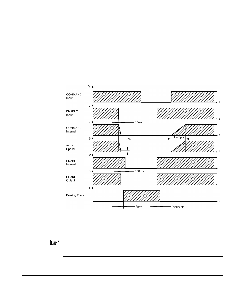
Servo Motor Holding-Brake Control Functional Description
A 24V holding brake in the servo motor is controlled directly by the 17S drive
through software-selectable BRAKE parameter settings. The time and functional
relationships betw een the EN ABLE signa l, speed setpoint, speed an d braki ng f orce
are shown in the following diagram.
During the fixed ENABLE delay time of 100 ms, the speed setpoint of the drive is
internally driven down a 10 ms ramp to 0V. The 3 % region of actual speed is
scaled to V
LIM
.
Note: The set and rel ease t imes of the ho lding brak e v ary with the servo motor a nd
thus must be considered when setting parameters.
Continued on next page
55
Page 68
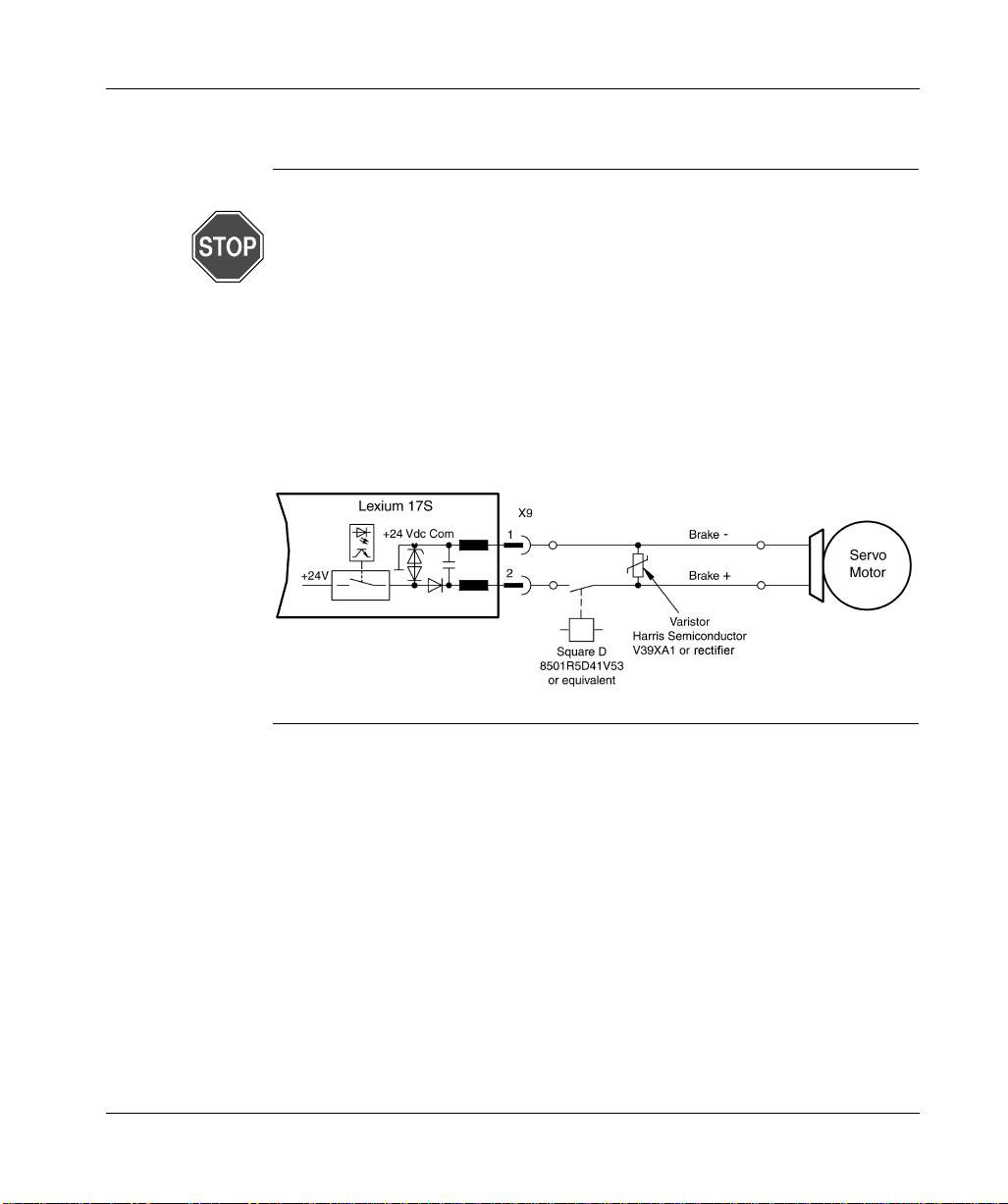
Power Wiring, continued
WARNING!
IMPACT HAZARD
The off-the-shelf configuration of the holding-brake function does not ensure the
safety of personnel. In order to make this function safe for personnel, a normallyopen contact and a user-installed suppressor device (varistor) must be
incor porated into the brake circuit as shown in the following diagram.
Failure to observe this precaution can result in severe injury or equipment
damage.
56
Page 69

Signal Wiring
Lexium BPH Resolver Connection (excluded BPH055)
The following diagram shows the connections between the resolver and the 17S
drive.
Note: The standard Lexium BPH series servo motors are equipped with two-pole,
integral resolvers. The thermistor contact in the servo motor is connected via the
resolver cable to the 17S drive.
Continued on next page
57
Page 70
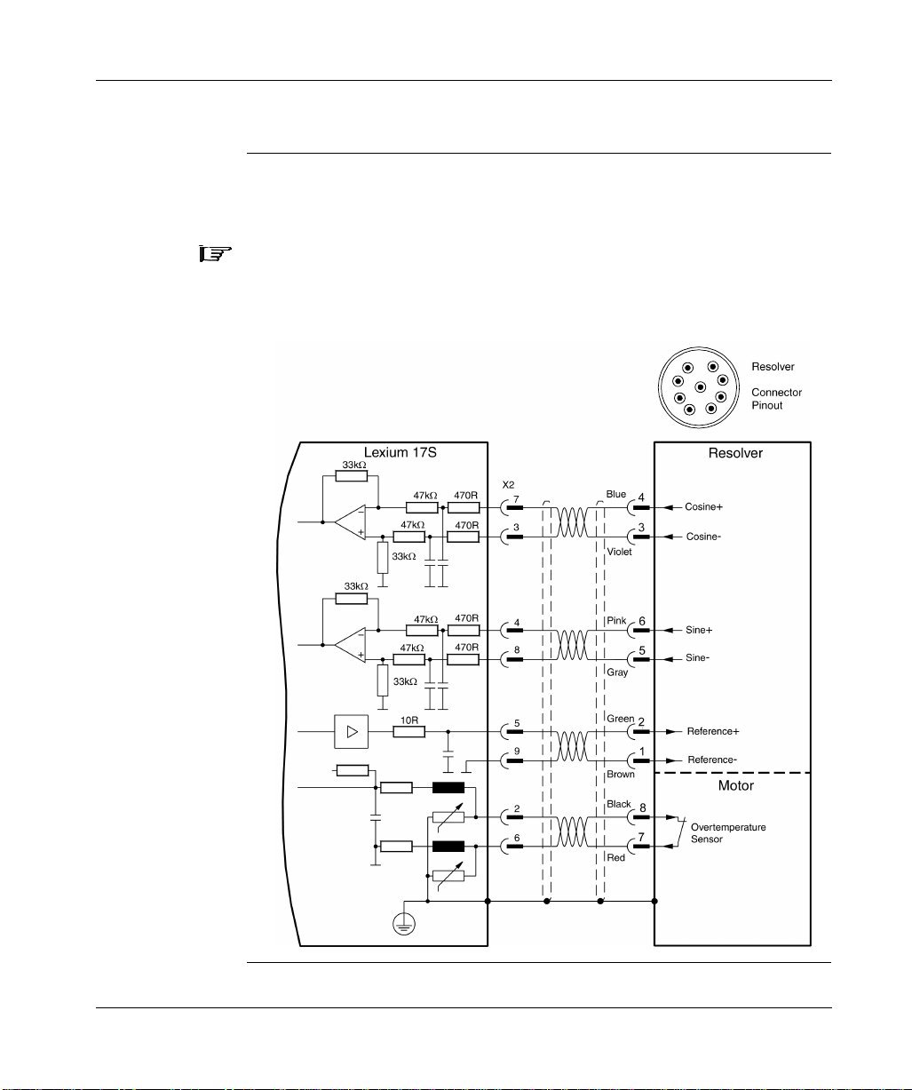
Signal Wiring, continued
Lexium BPH055 Resolver Connection
The following diagram shows the connections between the resolver and the 17S
drive.
Note: The BPH055 servo motors are equipped with two-pole, integral resolvers.
The thermistor contact in the servo motor is connected via the resolver cable to the
17S drive.
1
8
2
9
7
6
4
5
BPH055
3
58
Continued on next page
Page 71

Signal Wiring, continued
Encoder Input Connection
The following diagram shows the encoder input connections between the encoder
and the 17S drive.
Note: The BPH series servo motors can be optionally fitted with a single-turn or
multi-turn sine-cosine encoder, which is used by the 17S drive as the primary
feedback device for operations requiring highly precise positioning or extremely
smooth running. In additi on , the thermi sto r co ntact in the servo motor is co nnected
via the encoder cable to the 17S drive.
Continued on next page
59
Page 72
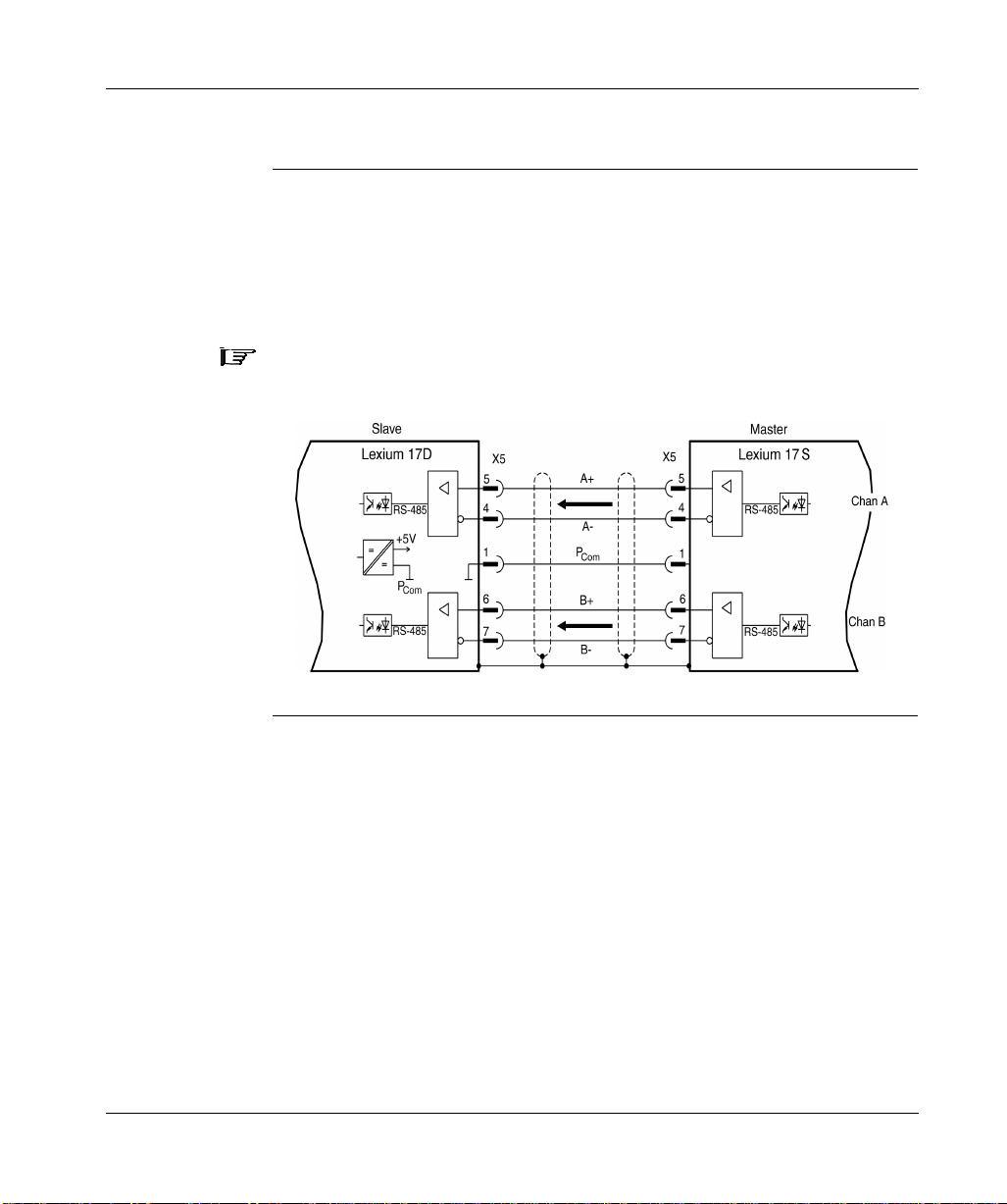
Signal Wiring, continued
Auxiliary Encoder Interface
l Master-slave Operation of Drives Diagram.
The encoder interface can be used to link one or more drives together in a
master-slave operation, as shown in the following diagram. Up to 16 slave
drives can be controlled by a designated master drive via the encoder output.
The UniLink software allows you to setup the parameters for the slave drive(s)
and to adjust the gear ratio (number of pulses/turn).
Note: In this configur ation , the anal og setpoi nt inputs are disab led a nd Anal og Com
and I/O Com (connector X3) must be connected.
60
Page 73
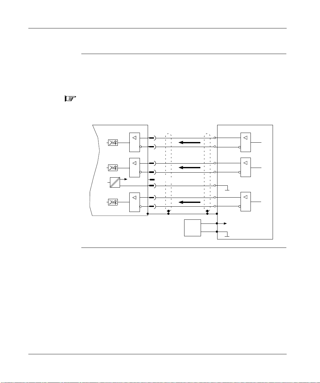
Signal Wiring, continued
l Incremental-Encoder Input Connection.
The following diagram shows the incremental encoder input connections between
the 17 drive and an external incremental encoder.
Note: The receivers are supplied from an internal supply voltage.
P
Incremental encoder is powered by an external Power Supply.
must always be connected to the encoder ground.
Com
Lexium 17S
RS-485
RS-485
=
=
RS-485
5V
X5
5
4
2
3
8
1
6
7
Reserved
A+
A-
M+
M-
Com
P
B+
B-
Power
Supply
Incremental encoder
Chan A
Marker
Gnd
Chan B
+
+Vdc
Gnd
RS-485
RS-485
RS-485
61
Page 74

Signal Wiring, continued
l SSI Encoder Input Connection:
The following diagram shows the connections between an external SSI encoder
and the drive.
Note: The drivers are supplied from an internal supply voltage.
P
SSI encoder is powered by an exter nal Power Supply
must always be connected to the encoder ground.
Com
Lexium 17S
RS-485
=
=
=
=
RS-485
5V
X5
6
7
8
1
4
5
Reserved
Data
Data
P
Clock
Clock
Power
Supply
Com
SSI encoder
RS-485
Gnd
RS-485
+
+Vdc
Gnd
62
Page 75

Analog Input Connection
Analog Inputs The following diagram shows the connections between the two fully programmable,
differential analog inputs on the 17S drive and a user device. (Refer to the list of
pre-programmed functions contained in the UniLink online help.)
Note: The Analog Com must always be connected to the user device Com as a
ground reference.
63
Page 76

Fault Relay and Digital I/O Connection
Digital Inputs and Outputs
The followi ng diag r am sh ows the conne ction s betw een th e f ault re la y, the four fully programmable, digital inputs, dedicated enable input and two digital outputs on the
17S drive and typical us er devices . (A list of pre-pr ogramme d functions is co ntained
in the UniLink online help.)
F
Ω
Ω
64
Continued on next page
Page 77

Fault Relay and Digi tal I/O Connection, continued
Using Functions Pre-programmed into the Drive
Fault Relay- The isolated fault relay contacts are closed during normal operation
and open when a fault condition exists. The relay state is not affected by the enable
signal, I2t limit or warnings. All faults cause the Fault RA/RB contact to open and
the switch-off of the output stage. A list of error messages can be found in chapter
Troubleshooting.
Digital Inputs 1, 2, 3 and 4 - You can use the four digital inputs to initiate preprogrammed functions that are stored in the drive.
Digital Outputs 1 and 2 - You can use the two digital outputs to send messages
from pre-programmed funct ion s that are sto r ed in the drive.
Enable Input - This is a dedicated, level-sensitive (as opposed to edge-sensitive)
hardware input which wil l enable the output stage of the drive when 24 Vdc is
applied and no fault conditions exist.
Note: The hardware enable is powered up upon detection of state sense versus
transition sensitivity. Refer to the UniLink on-line help for software enable
information.
65
Page 78

Serial Communications Connection
RS-232 Null Modem Type Communication Connection Diagram
The following diagram depicts the RS-232 communication connection between the
Lexium 17S and a PC.
See wiring in Append ix C
The setting of the operating, position control, and motion-block parameters can be
carried out with an ordinary commercial PC.
Connect the PC interface (X6) of the servo amplifier while the supply to the
equipment is switched off via a normal commercial 3-core cable to a serial
interface on the PC. Do not use a null-modem link cable!
The interface is electrically isolated through an optocoupler, and is at the same
potential as the CANopen interface.
66
Page 79

At a Glance
System Operation
5
What’s in this Chapter
This chapter provides information on operating the Lex ium 17S s eries s ervo drives
and includes the following topics:
Topic Page
Powering up and powering down the system 68
Procedure for verifying system operation 71
Front panel controls and indicators 73
67
Page 80
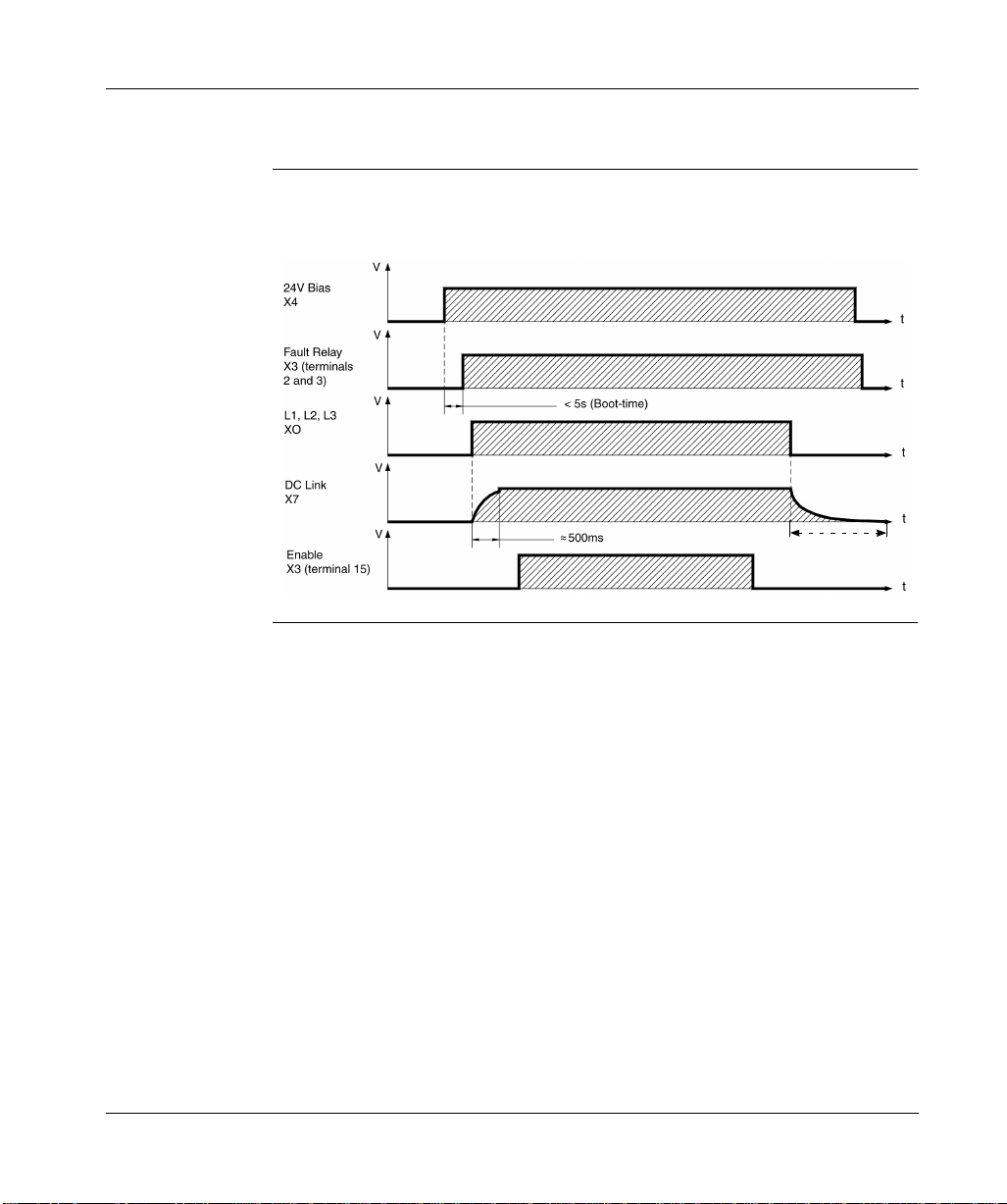
Powering Up and Powering Down the System
Power-on and Power-off Characteristics
The following diagram illustrates the functional sequence that occurs when the
drive is turned on and off.
5 min.
68
Page 81

Power ing Up and Powering Down the System
Stop Function If a fault occurs the output stage of the servo amplifier is switched off and the
Emergency Stop strategies
Fault RA/ RB contact is op ened. In addi tion, a global error signal ca n be giv en out at
one of the digital outputs (terminals X3/16 and X3/17). These signals can be used
by the higher-level control to finish the current PLC cycle or to shut down the drive
(with additional brake or similar.).
Instruments which are equipped with a selected "Brake" function use a special
sequence for switching off the output stage.
The Stop functions are defined in EN 60204 (VDE 0113), Para. 9.2.2, 9.2.5.3.
There are three categories of Stop functions:
l Category 0: Shut down by immediately switching off the supply of energy to the
drive machinery (i.e an uncontrolled shut-down);
l Category 1: A controlled shut-down, during which the supply of energy to the
drive machinery is mainta ined to perf orm the shut-d own, and where the energy
supply is only interrupted when the shut-down has been completed;
l Category 2: A controlled shut-down, where the supply of energy to the drive
machinery is maintained.
Every machine must be equipped with a Stop function to Category 0. Stop
functions to Categories I and/or 2 must be provided if the safety or functional
requirements of the machine make this necessary.
The Emergency Stop function is defined in EN 60204 (VDE 0113), Para. 9.2.5.4.
Implementation of the Emergency Stop function:
l Category 0: The controller is switched to "disable", the el ectrical supply
(400VAC) is disconnected.
The motor must be held by an electromagnet ic holding device (brake).
In multiaxis systems with connected DC-link bus (intermediate circuit) the
motor leads have to be disconnected by a changeover switch and shortcircuited by resistors connected in a star configuration.
l Category 1: If hazardous conditions can result from an eme rge ncy stop switch-
off with an unbraked run-down, then the drive can be switched off by a
controlled shut-down.
Stop Category 1 permits electromotive braking with a switch-off when zero
speed has been reached. Safe shut-down can be achieved, when the loss of
the mains supply is not rated as a fault and the co ntro l ta kes over the disabling
of the servo amplifier.
In the normal situation, only the supply power is switched off in a safe manner.
The 24V auxiliary supply remains switched on.
69
Page 82
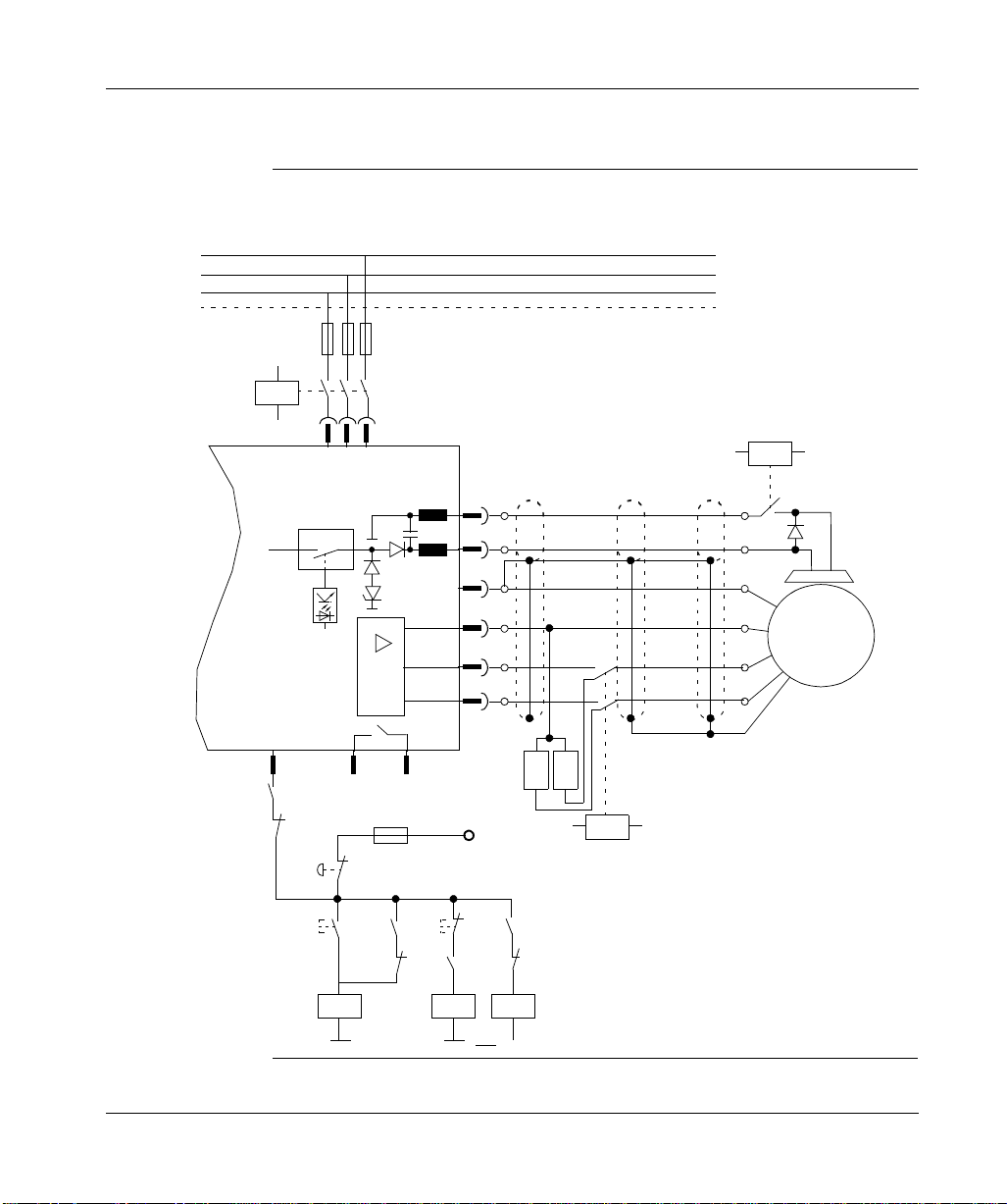
Powering Up and Powering Down the System
Wiring example Stop and Emergency Stop function (Category 0)
L1
L2
L3
PE
K10
XOA
3 2 1
LEXIUM 17S
24 Vdc Com
24 Vdc
Enable
X3 15 2 3
K10
Fault RA/RB
K11
Emergency-Off
K10 K10
+24Vdc Com
K20
X9
1
2
3
4
5
6
B RB
R
F
OFFON
+24Vdc
K30 K11K11
K20K10K30
Brake-
Brake+
Gnd
(Green)
W2
V2
U2
K30
K11 is normally closed
(no fault of equipement)
Servo
Motor
70
Page 83
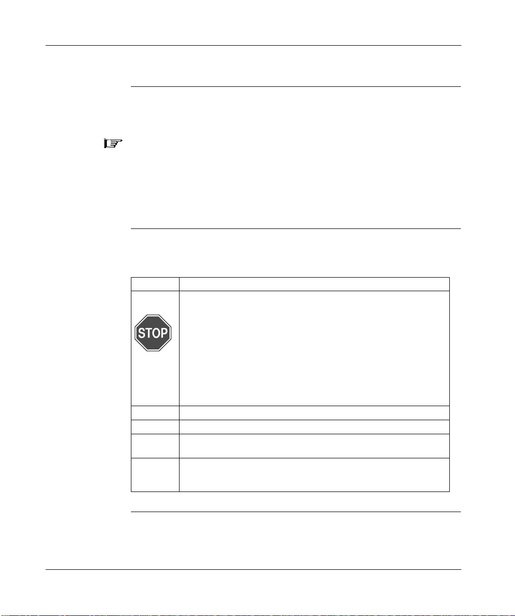
Procedure for Verifying System Operation
Overview The following procedure and associated information verifies operation of the
system without creating a hazard to personnel or jeopardizing the equipment.
Note: Default parameters for each Lexium BPH series motor are loaded into your
drive at the factory and contain valid and safe values for the current and speed
controllers. A d atabase f or the servo motor par amet ers is st ored in t he driv e. D uring
commissioning, you must select the data set for the connected servo motor and
store it in the drive. For most applications, these settings will provide good servo
loop efficiency. For a description of all parameters and motor tuning, see the
UniLink online help.
Quick Tuning Procedure
This procedure will enable you to rapidly assess the op erational readiness of the
system.
Step Action
1 Disconnect the drive from the power source.
WARNING!
MECHANICAL MOVEMENT HAZARD
Ensure the motor is securely mounted and that the load is disconnected from the motor.
Failure to observe this precaution can result in severe injury or equipment damage.
2 Ensure 0 V is applied to the enable input (connector X3, terminal 15).
3 Connect the PC to the drive via the serial communications cable.
4 Turn on the 24 Vdc bias supply. After the initialization procedure
(< 5 seconds) the status is shown in the LED display.
5 Switch on the PC, start the UniLink software and select the serial
communication port to which the drive is connected. (The parameters that
are stored in the SRAM of the drive are transferred to the PC.)
Continued on next page
71
Page 84
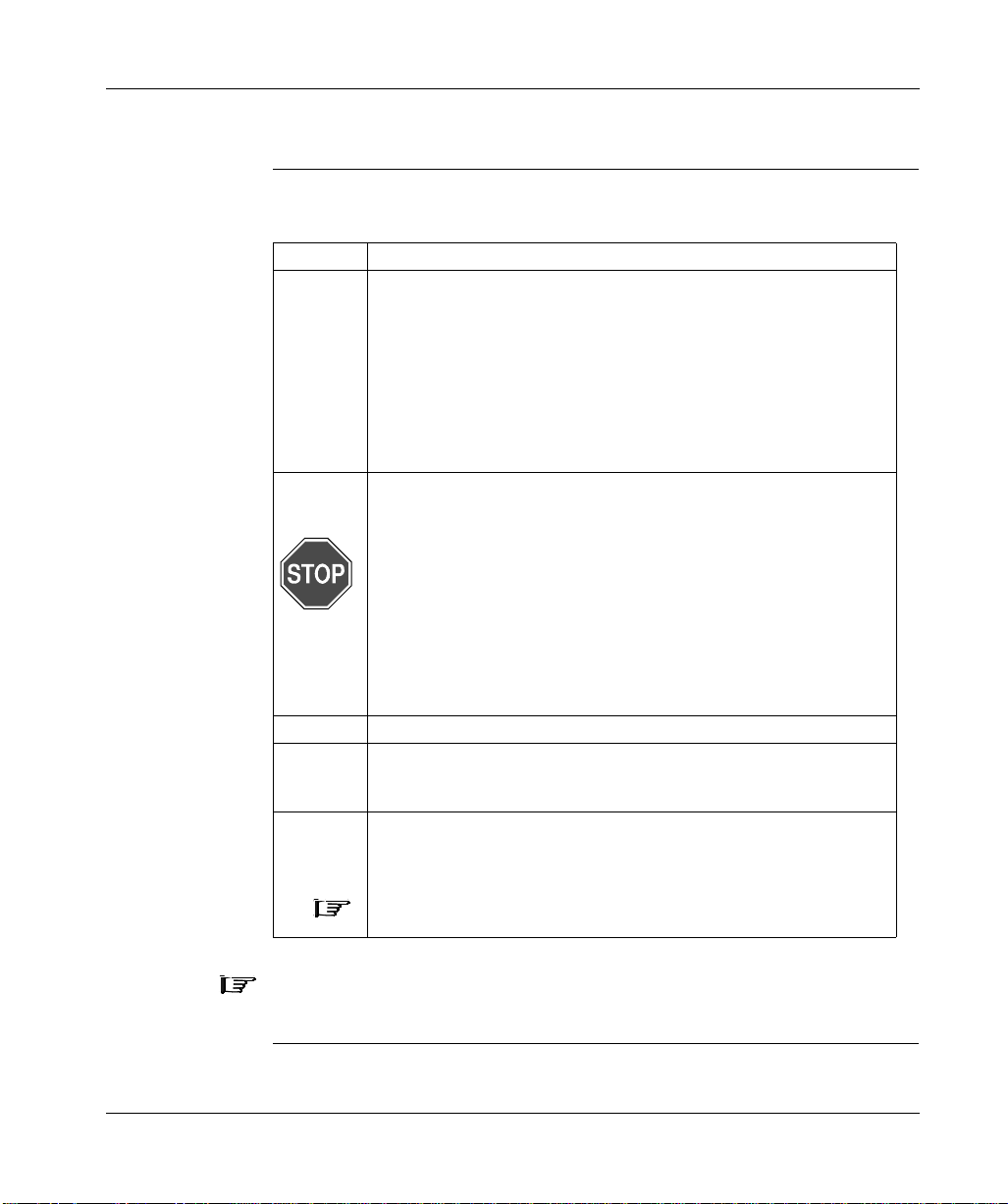
Procedure for Verifying System Operation, continued
Quick Tuning
Procedure,
continued
Step Action
6 Use the UniLink software to check/establish the following:
l Drive Parameters - Set/restore the drive parameters to the factory
default values.
l Supply voltage - Set the supply voltage to the actual mains supply
voltage.
l Servo Motor - Select the applicable BPH servo motor.
l Feedback - Ensure the feedback matches the feedback unit in the
servo motor.
7 Check safety devices such as hardware limit switches, emergency stop
8 Turn on the AC mains power supply.
9 Enable 24 Vdc on connector X3, terminal 15. Observe that 500 ms after
10 Using the UniLink Oscilloscope Service Function, program a small 50-rpm
circuitry and so forth.
WARNING!
MECHANICAL MOVEMENT HAZARD
Ensure personnel, tools and all other obstructions are clear of the equipment.
Failure to observe this precaution can result in severe injury or equipment damage.
the power supply was switched on, the servo motor is motionless with a
standstill torque of M
velocity command. If the servo motor oscillates, the Kp parameter in the
"speed controller" menu page must be adjusted.
.
0
72
Note: The Kp parameter may have to be adjusted after connecting the
load. Refer to UniLink on-line help for more tuning information.
Note: The hardware enable is powered up upon detection of state sense versus
transition sensitivity.
Page 85
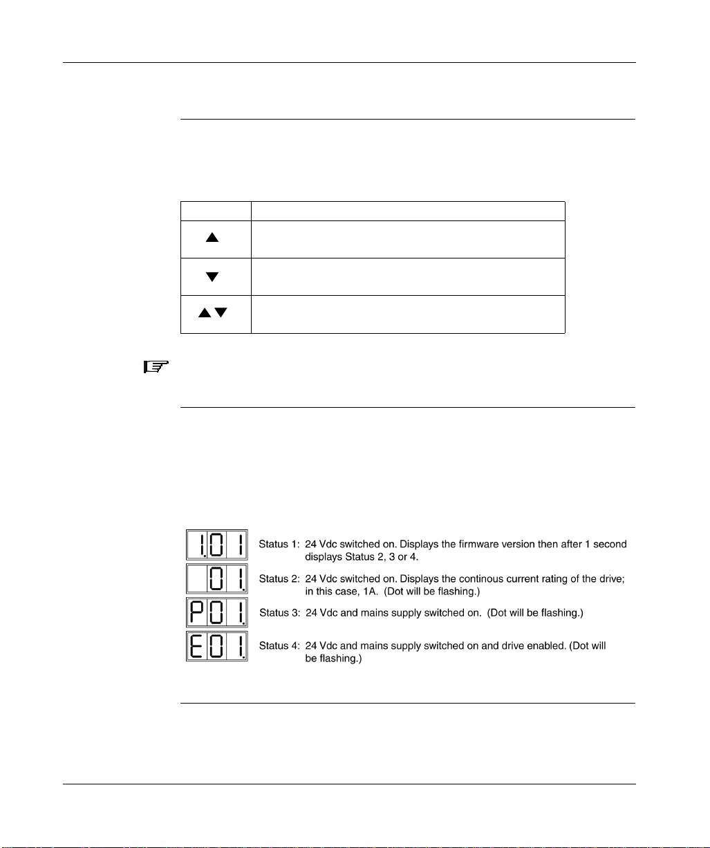
Front Panel Controls and Indicators
Keypad Operation
The operation of the keypad on the front panel of the 17S drive is described in the
following table. The two keys can be used (as an alternative to using the PC) to
specify and enter the SERCOS address for the drive.
Key Function
Press once
Press twice in rapid succession: Increments address by 10
Press once: Decrements address by 1
Press twice in rapid succession: Decrements address by 10
Press and hold right key, then press left key: Enters the
address specified above.
: Increments address by 1
Note: The drive must be powered down then powered up again to confirm an
address change.
LED Display The alphanumeric display indicates drive power status conditions, error codes and
warning codes. The power status condition s are shown below; error and warning
codes are identified and described in the Troubleshooting chapter.
Continued on next page
73
Page 86
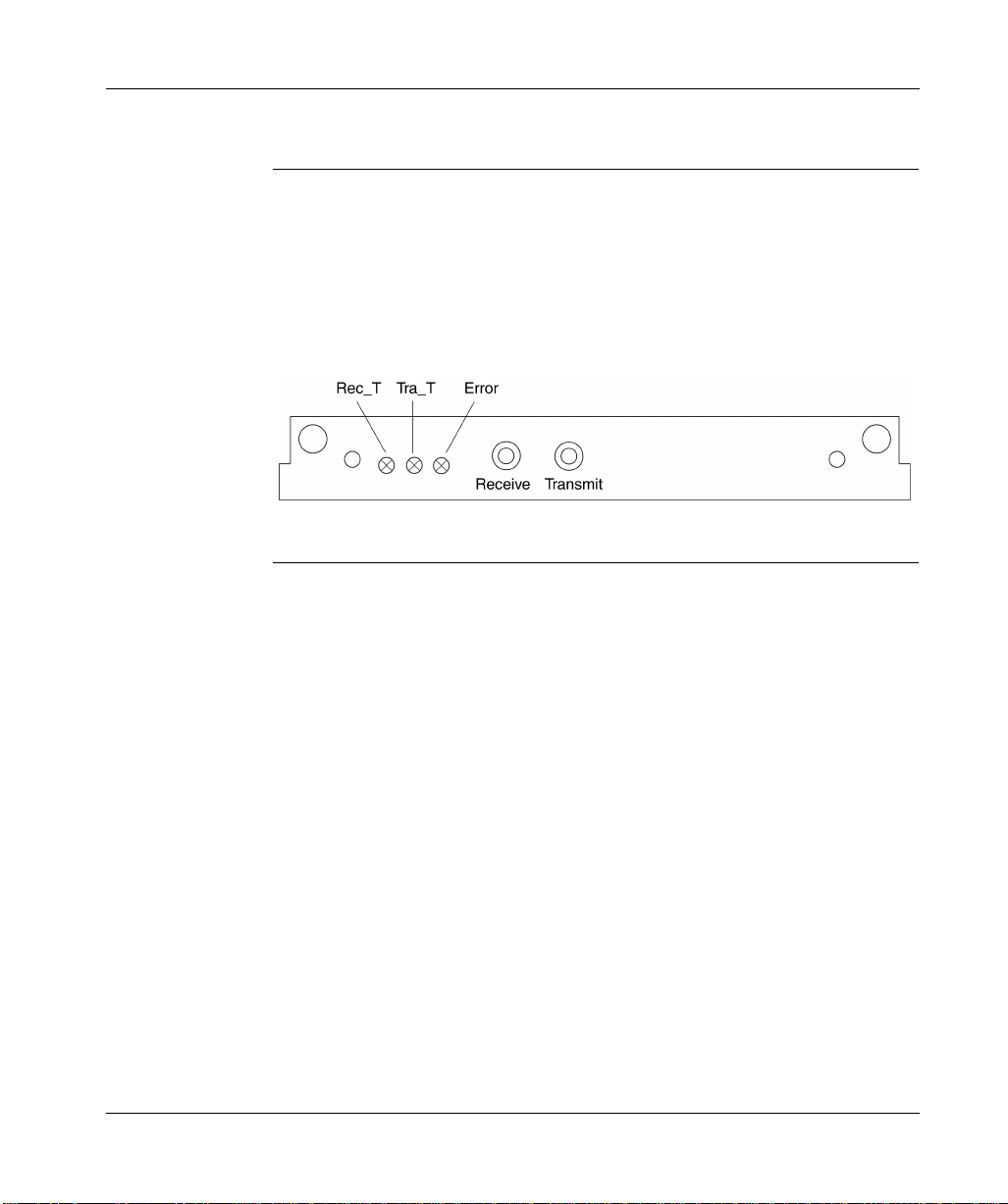
Front Panel Controls and Indicators, continued
SERCOS Communication LED Indicators
The following illustration shows the location of the three SERCOS communication
LED indicators on the SERCOS communication card at the top of the drive. The
Rec_T and Tra_T LEDs are green and (when illuminated) respectively indicate
information is being received or transmitted. The Error LED is red and illuminates
when a SERCOS communication error occurs.
74
Page 87
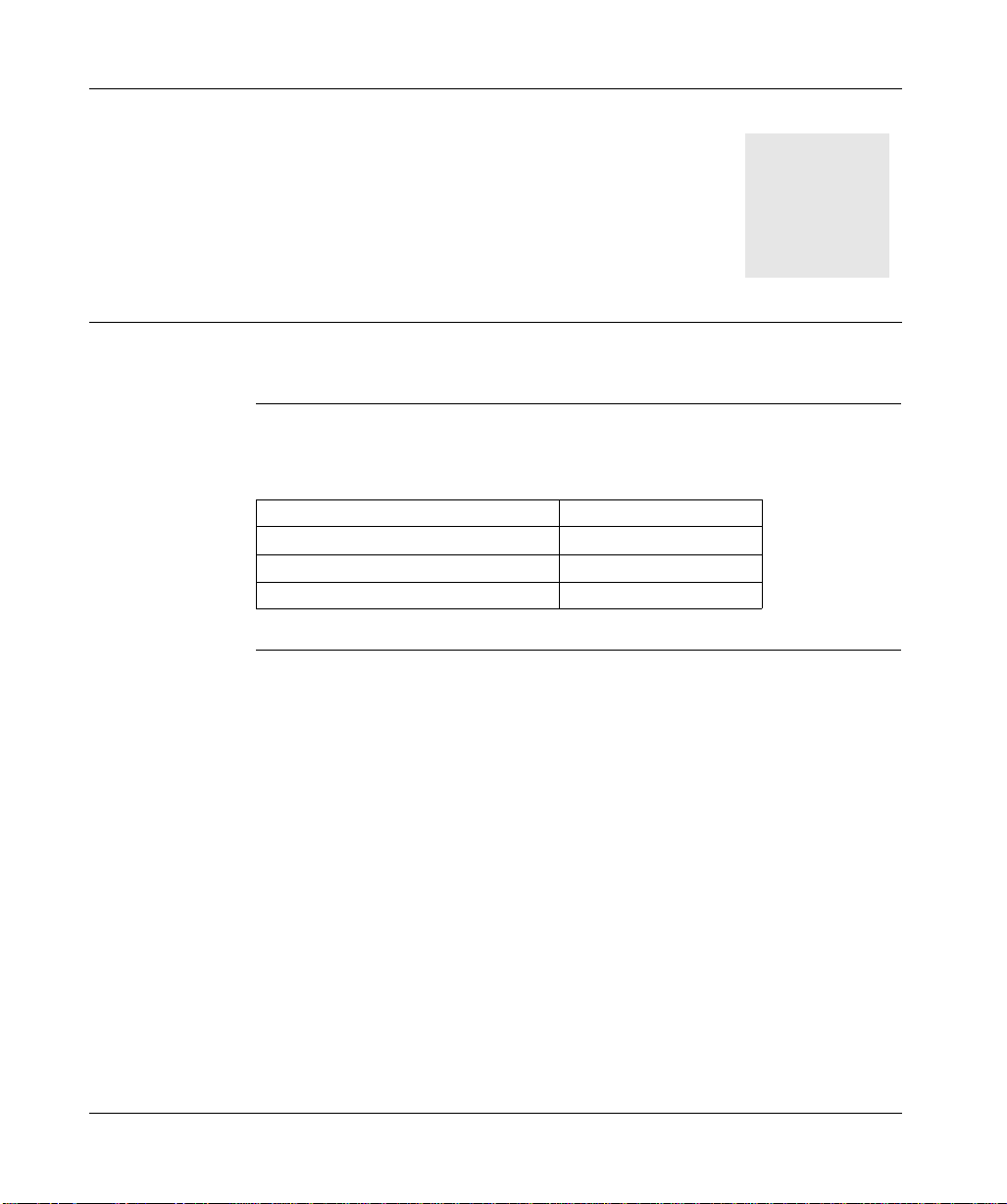
At a Glance
Troubleshooting
6
What’s in this Chapter
This chapter provides information on correcting problems with the 17S drive and
contains the following topics:
Topic Page
Warning messages 76 Error messages 77 Troubleshooting 81
75
Page 88

Warning Messages
Warning Identification and Description
A warning is generated when a non-fatal fault occurs. Non-fatal faults allow the
drive to remain enabled and the fault relay contact to remain closed. Either of the
programmable digital outputs can be programmed to indicate that a warning
condition has been det ected. The ca use of the warning is presented as an
alphanumeric code on the dri v e’s front panel LED displa y; these w arning c odes a re
identified and described in the following table.
Warning Code
n01 I²t warning Current threshold set by “I²t Message” parameter
n02 Regen power Power threshold set by “Max Regen Power”
n03 Following Faul t Following error threshold set by “Following Error”
n04 Response monitoring Response monitoring (fieldbus)is active. n05 Mains phase Mains phase missing. Can be disabled for single
n06 Sw limit-switch 1 Passed software limit-switch 1. n07 Sw limit-switch 2 Passed software limit-switch 2. n08 Motion task error A faulty motion task was started. n09 No “Home” reference point Motion task started with no “Home” reference
n10 Positive Limit Positive limit-switch activated. n11 Negative Limit Negative limit-switch activated. n12 Default values Only HIPERFACE®: motor default v alues loaded. n13 SERCOS interface SERCOS interface not functioning correctly. n14 HIPERFA CE®-reference
n15 Table error Velocity current table INXMODE 35 error n16 ... n31 Reserved reserved n32 Firmware beta version The firmware is not a released beta version A Reset RESET is active at DIGITAL IN x
Designation Explanation
was exceeded.
parameter was exceeded.
parameter was exceeded.
phase operation with the “Mains Phase Missing”
parameter.
point set.
mode
Attempt to reset while HIPERFACE®-reference mode was active.
76
Page 89

Error Messages
Error Identification and Description
Errors are generated when a fatal fault occurs. Fatal faults cause the drive to be
disabled, the br ak e (if ins talled ) to be activated and the fault relay c ontact s to open.
Either of the progr ammab le digita l outpu ts can also b e prog r ammed to indi cate th at
an error has been detected. The cause of the error is presented as an
alphanumeric code on the drive’s front panel LED display; these error codes are
identified and described in the following table.
Error Code
F01 Drive heat sink
F02 DC link voltage limit
F03 Following error limit
F04 Feedback signals missing
Error (Fault) Possible Cause/Corrective Action
overtemperature.
exceeded.
exceeded.
or incorrect.
- Improve ventilation.
- Reduce motion profile duty cycle.
- Check Parameter “Mains Supply Voltage” for correct setting.
- Supply voltage too high; use a mains transformer.
- Regen power limit was exceeded; adjust motion profile or install larger regen resistor.
- Increase I
range).
- SW ramp parameters set too large.
- Defective feedback device.
- Check for correct device type selected in “Feedback Type” parameter.
rms
or I
(keep within motor operating
peak
F05 DC-link voltage less then
factory preset (100V).
- Check feedback cable and connections.
Supply voltage not present or too low when drive was
enabled. Only enable the drive when the mains supply
voltage has been on longer than 500 ms.
Continued on next page
77
Page 90

Error Messages, continued
Error
Identification
and Description,
continued
Error Code
F06 Motor overtemperature. - I
F07 Internal 24 Vdc fault. Return drive to manufacturer F08 Motor speed limit
F09 EEPROM checksum error. Return drive to manufacturer.
F10 Flash-E PROM checksum
F11 Motor brake fault. - Brake parameter set to “WITH” when brake does not
Error (Fault) Possible Cause/Corrective Action
exceeded.
error.
or I
rms
- Defective motor
- If motor is not hot, check feedback cables and connectors.
- Reduce motion profile duty cycle
- Improve ventilation of the motor
- Feedback parameters not set correctly.
- Incorrect feedback wiring.
- Motor phases reversed.
- Check Parameter “Overspeed” fo r correct setting.
Return drive to manufacturer.
exist.
set too high.
peak
78
- Defective brake.
- Check motor power cable and connections.
F12 Motor phase missing. - Defective motor.
- Check motor power cable and connections
F13 Drive internal temperature
exceeded.
- Improve ventilation.
- Reduce motion profile duty cycle.
Continued on next page
Page 91

Error Messages, continued
Error
Identification
and Description,
continued
Error Code
F14 Drive output stage fault. - Check motor cable for damage or shorts.
F15 I²t m aximum value
F16 Mains supply missing two
F17 A/D converter error. Return drive to manufacturer F18 Regen circuit faulty or
Error (Fault) Possible Cause/Corrective Action
exceeded.
or three phases.
incorrect setting.
- Output module is overheated; improve ventilation.
- Short-circuit or short to ground in the external Regen resistor.
- Motor has short-circuit/ground short; replace motor.
- Output stage is faulty; return drive to manufacturer.
- I
or I
rms
- Reduce motion profile duty cycle.
- Check mains fuses.
- Check mains wiring and connections on drive.
- Check jumper on X8 if using internal regen resitor.
- Check wiring of external regen resistor if used.
set incorrectly.
peak
- Check fuses of external regen resistor.
F19 Mains supply missing one
phase.
F20 Slot fault Hardware fault of the expa nsion card F21 Handling fault Software fault of the ex pansion card F22 Reserved Reserved F23 Reserved Reserved F24 Reserved Reserved F25 Commutation error Encoder system only
- For single phase operation, set “Phase Missing” parameter to “no message”.
- Check mains supply fuses.
- Check mains connector on drive.
- Check mains supply wiring.
79
Page 92

Error
Error (Fault) Possible Cause/Corrective Action
Code
F26 Reserved Reserved F27 Reserved Reserved F28 Reserved Reserved F29 SERCOS error SERCOS system s only F30 SERCOS time out SERCOS systems only F31 Reserved Reserved F32 System error System software not responding correctly, return drive
to manufacturer.
80
Page 93

Troubleshooting
Problems, Possible Causes and Corrective Actions
The following table id entifies som e common system problems, their possible
causes and recommended corrective actions. However, the configuration of your
installation may create other reasons, and consequently other corrections, for the
problem.
Problem Possible Causes Corrective Actions
No communication with PC
Motor does not rotate
- Wrong cable used.
- Cable plugged into wrong position in drive or PC.
- Wrong PC interface selected.
- Drive not enabled.
- Break in SERCOS fiber optic cable.
- Motor phases swapped.
- Brake not released.
- Motor is mechanically blocked.
- Motor pole number set incorrectly.
- Feedback set up incorrectly .
- Check cable.
- Plug cable into the correct sockets on the drive and PC.
- Select correct interface.
- Apply enable signal
- Check cable
- Correct motor phase sequence
- Check brake control
- Check mechanism
- Set motor pole number.
- Set up feedback correctly.
Continued on next page
81
Page 94

Troubleshooting, continued
Problems,
Possible Causes
and Correct ive
Actions,
continued
Problem Possible Causes Corrective Actions
Motor oscillates - Gain too high (speed controller).
Poor drive performance (drive too soft)
- Shielding in feedback cable has a break.
- Kp (speed controller) too low.
- Tn (speed controller) too high.
- Reduce Kp (speed controller).
- Replace feedback cable.
- Increase Kp (speed controller).
- Use motor default value for Tn (speed controller).
Motor runs roughly
- PID-T2 too high.
- T-Tacho too high.
- Kp (speed controller) too high.
- Tn (speed controller) too low.
- PID-T2 too low.
- T-Tacho too low.
- Reduce PID-T2.
- Reduce T-Tacho.
- Reduce Kp (speed controller).
- Use motor default value for Tn (speed controller).
- Increase PID-T2.
- Increase T -Tacho.
82
Page 95

At a Glance
Specifications
A
What’s in this Appendix
This appendix contains the following topics.
Topic Page
Performance specifications
Environmental and mechanical specifications
Electrical specifications
Wire specifications (recommended)
84
85
87
99
83
Page 96
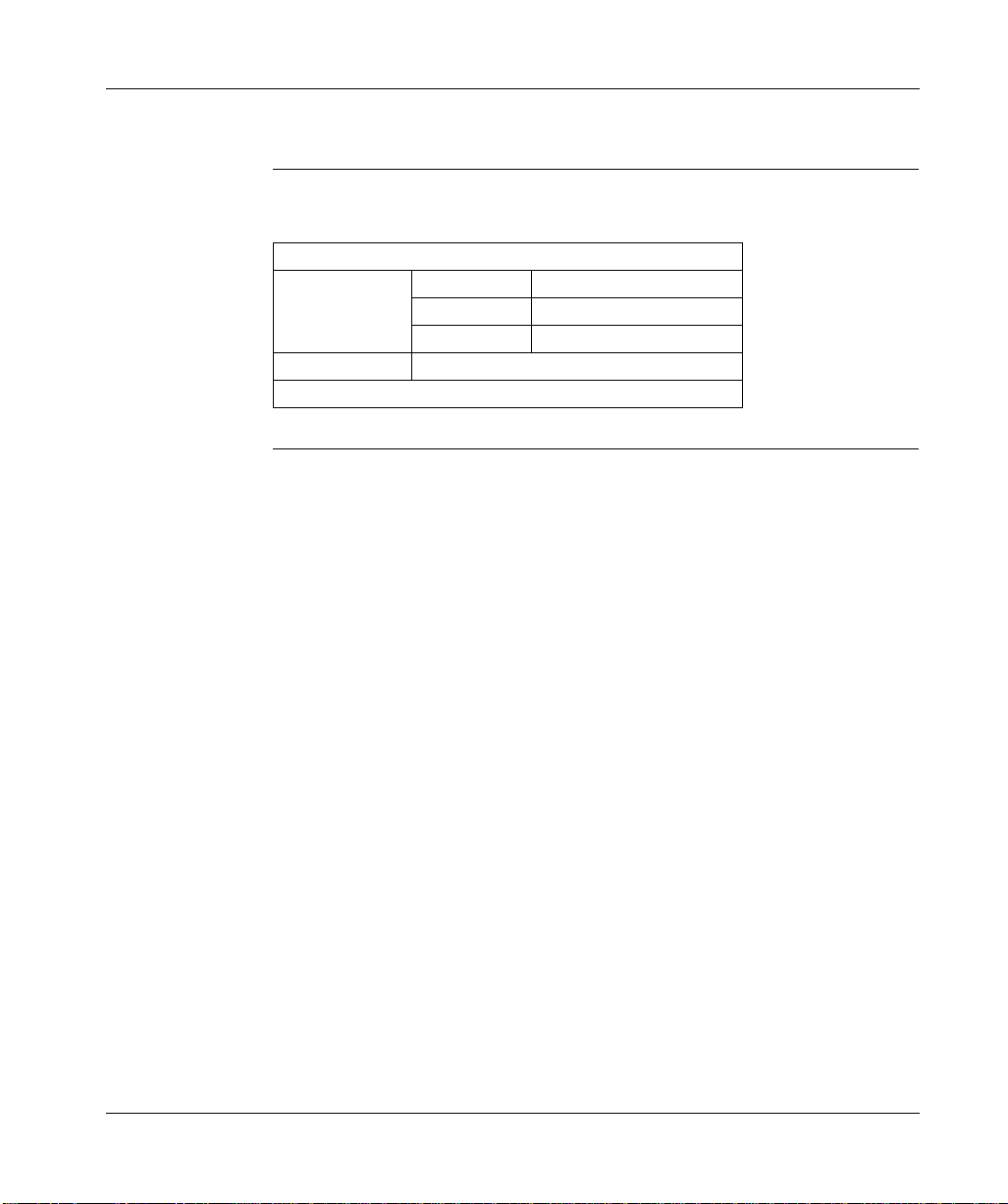
Perf ormance Specifications
Performance Specifications Table
The following table lists 17S performance specifications.
PERFORMANCE
Servo updates Torque 62.5 µs
Velocity 250 µs Position 250 µs
Tuning procedure UniLink application*
* Included in AM0CSW001V•00 (CD-ROM)
84
Page 97
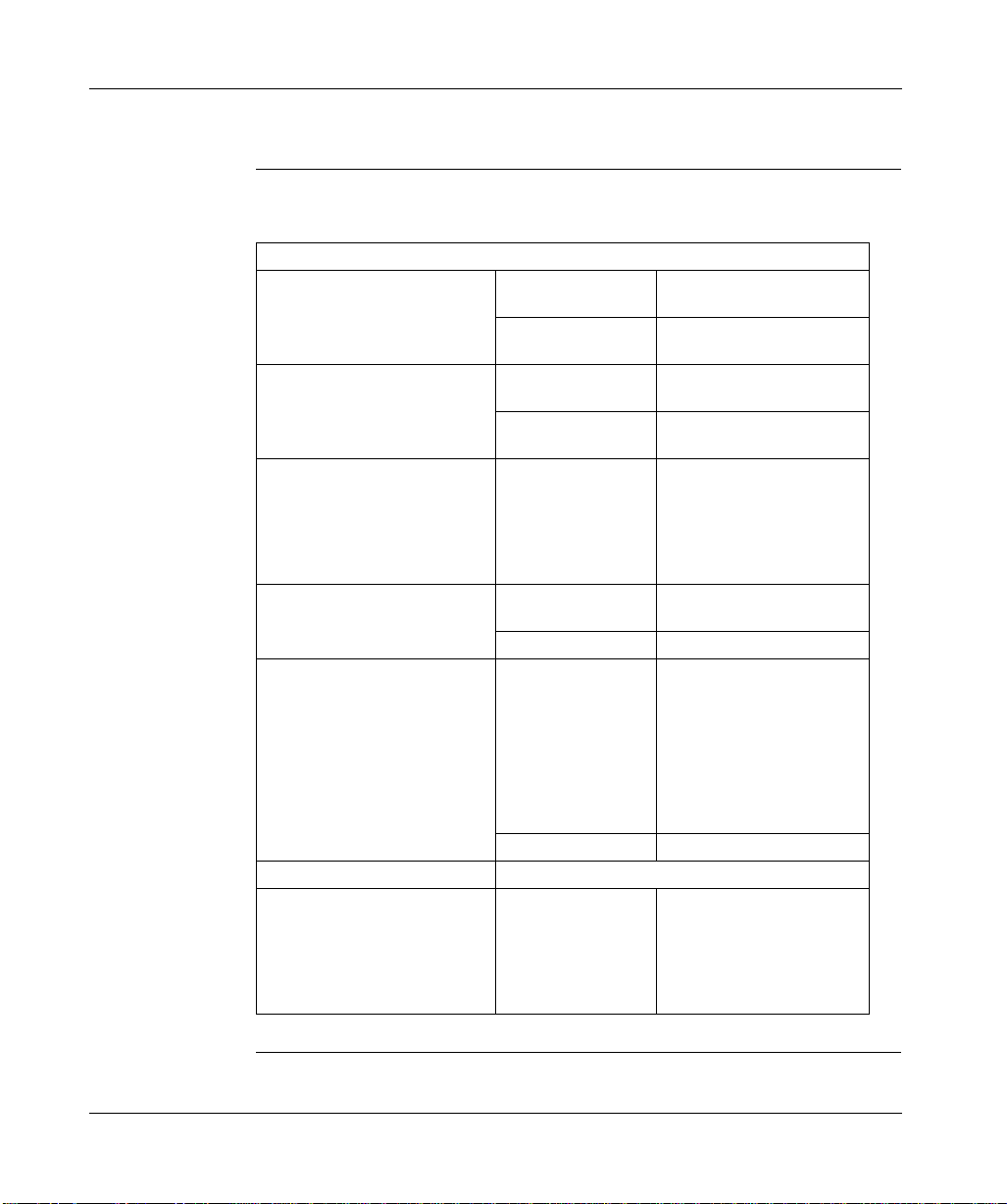
Environmental and Mechanical Specifications
Environmental Specifications Table
The following table provides 17S environmental specifications.
ENVIRONMENTAL
Storage High temperature,
non–operating
Low temperature,
non–operating
Humidity Non–operating 95% RH maximum,
Operating 85% RH maximum,
Operating temperature (ambient measured at fan inlet)
Vibration (operational) 10 ... 57 Hz Sinusoidal, 0.75 mm
Air pressure Operating:
Contaminants Pollution degree 2, as defined in EN60204/EN50178 Cooling Models:
Full power
With linear derating
2,5% / °C
(avail able p ower: 75% of
rated output at 55
57 ... 150 Hz 1.0 g
Full power
With linear derating
1,5% / 100m
(available power: 75% of rated output at 2500m)
Transport 57 kPa (4540 m)
MHDS1004N00
MHDS1008N00
MHDS1017N00
MHDS1028N00
MHDS1056N00
°
C)
°C maximum
+70
°C minimum
–25
non-condensing
non-condensing
0 ... 45°C
45 ... 55°C max
amplitude
1000 m (90 kPa)
1000 ... 2500m (73kPa) max
Integrated heatsink with internal fan.
Continued on next page
85
Page 98
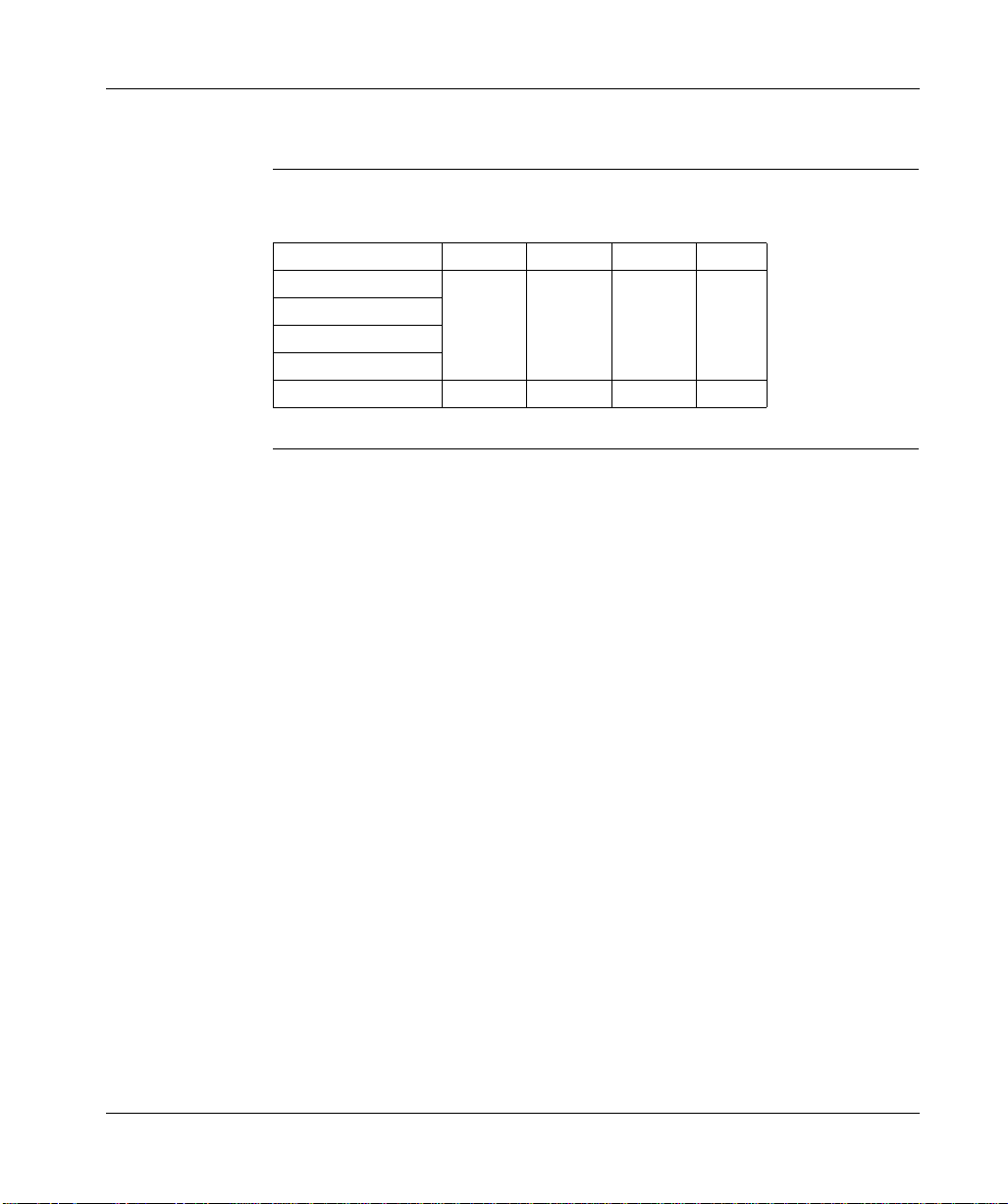
Environmental and Mechanical Specifications, continued
Mechanical Specifications Table
The following table provides 17S mechanical sp ecifications.
Drive Model Number Height Width Depth Weight
MHDS1004N00 325 mm 70 mm 265 mm 2.5 kg MHDS1008N00 MHDS1017N00 MHDS1028N00 MHDS1056N00 325 mm 120 mm 265 mm 3.0 kg
86
Page 99
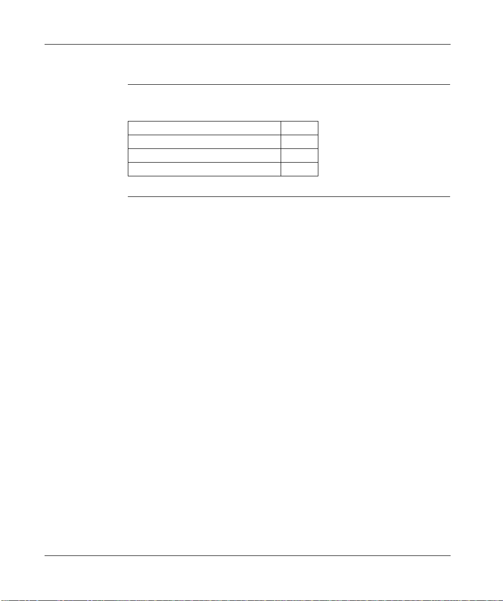
Electrical Specifications
What’s in this Section
This section provides tables for the following topics.
Topic Page
Electrical Specifications - Power 88 Electrical Specifications - Regen resistor 92 Electrical Specifications - Signal 93
87
Page 100

Electrical Specifications - Power
Line Input Specifications Table
The following table provides 17S line input specifications.
LINE INPUT
Voltage 208 Vac -10% 60 Hz, 230 Vac -10% 50 Hz.
480 Vac +10%, 50 - 60 Hz, three-phase*
Current MHDS1004N00 1.8 A RMS**
MHDS1008N00 3.6 A RMS MHDS1017N00 7.2 A RMS MHDS1028N00 12 A RMS
MHDS1056N00 24 A RMS Inrush current Internally limited Efficiency Greater than 98% * Read carefully “Electrical considerations”
** Single-phase operation permitted.
Continued on next page
88
 Loading...