

Page 1
2354235 11/2008
Altivar 61/71
Modbus TCP/IP
Ethernet card
User manual
VW3 A3 310
11/2009
1755879
www.schneider-electric.com
Page 2

Table of Contents
1. Important Information _______________________________________________________________________________________ 4
2. Before you begin___________________________________________________________________________________________ 5
3. Documentation structure_____________________________________________________________________________________ 6
4. Introduction_______________________________________________________________________________________________ 7
4. 1. Presentation _________________________________________________________________________________________ 7
4. 2. Evolutions du logiciel __________________________________________________________________________________ 7
4. 3. Notation ____________________________________________________________________________________________ 7
5. Hardware setup ___________________________________________________________________________________________ 8
5. 1. Receipt _____________________________________________________________________________________________ 8
5. 2. Hardware description __________________________________________________________________________________ 8
5. 3. Installing the card in the drive____________________________________________________________________________ 8
6. Connecting to the Ethernet network ____________________________________________________________________________ 9
6. 1. Card RJ45 connector pinout_____________________________________________________________________________ 9
6. 2. Example of connection to an Ethernet network ______________________________________________________________ 9
6. 3. Ethernet network connection elements____________________________________________________________________ 10
7. Ethernet menu ___________________________________________________________________________________________ 11
7. 1. Access to Ethernet menu via graphic display terminal________________________________________________________ 11
7. 2. Access to Ethernet menu via the integrated display terminal ___________________________________________________ 11
7. 3. Ethernet menu parameters_____________________________________________________________________________ 12
8. Configuration ____________________________________________________________________________________________ 15
8. 1. List of functions to be configured ________________________________________________________________________ 15
8. 2. Configuring IP addresses ______________________________________________________________________________ 16
8. 3. Reserving control ____________________________________________________________________________________ 18
8. 4. Configuring IO Scanning_______________________________________________________________________________ 18
8. 5. Configuring the control ________________________________________________________________________________ 19
8. 6. Configuring the fault management _______________________________________________________________________ 22
8. 7. Configuring monitored parameters _______________________________________________________________________ 24
9. Diagnostics ______________________________________________________________________________________________ 25
9. 1. Signalling LEDs _____________________________________________________________________________________ 25
9. 2. Available information _________________________________________________________________________________ 25
9. 3. Monitoring the control _________________________________________________________________________________ 26
9. 4. Troubleshooting the communication fault __________________________________________________________________ 27
9. 5. Troubleshooting the card fault __________________________________________________________________________ 28
10. Software setup __________________________________________________________________________________________ 29
10. 1. List of services supported_____________________________________________________________________________ 29
10. 2. TCP connections ___________________________________________________________________________________ 29
11. Modbus TCP server ______________________________________________________________________________________ 30
11. 1. Modbus TCP frames_________________________________________________________________________________ 30
11. 2. Drive Modbus servers________________________________________________________________________________ 30
11. 3. Ethernet card parameters_____________________________________________________________________________ 31
11. 4. List of Modbus functions supported _____________________________________________________________________ 34
11. 5. “Read Holding Registers” (3) function ___________________________________________________________________ 34
11. 6. “Write Single Register” (6) function______________________________________________________________________ 35
11. 7. “Write Multiple Registers” (16 = 16#10) function ___________________________________________________________ 36
11. 8. “Read/Write Multiple Registers” (23 = 16#17) function_______________________________________________________ 37
11. 9. “Read Device Identification” (43 = 16#2B) function _________________________________________________________ 38
12. IO Scanning service ______________________________________________________________________________________ 39
12. 1. Presentation _______________________________________________________________________________________ 39
12. 2. Periodic variables ___________________________________________________________________________________ 39
12. 3. Address table ______________________________________________________________________________________ 40
13. FDR service ____________________________________________________________________________________________ 41
13. 1. Presentation _______________________________________________________________________________________ 41
13. 2. Local configuration __________________________________________________________________________________ 42
13. 3. Downloaded configuration ____________________________________________________________________________ 43
13. 4. Periodic saving _____________________________________________________________________________________ 45
13. 5. Other commands ___________________________________________________________________________________ 45
13. 6. Configuration file____________________________________________________________________________________ 45
2 1755879 11/2009
Page 3

Table of Contents
14. Standard Web server _____________________________________________________________________________________ 46
14. 1. Web server functions ________________________________________________________________________________ 46
14. 2. Applets ___________________________________________________________________________________________ 47
14. 3. Access to the Web server_____________________________________________________________________________ 48
14. 4. Web server user interface_____________________________________________________________________________ 49
14. 5. “Home” menu ______________________________________________________________________________________ 49
14. 6. “Monitoring” menu___________________________________________________________________________________ 49
14. 7. “Altivar Viewer” page ________________________________________________________________________________ 50
14. 8. “Data Viewer” page__________________________________________________________________________________ 51
14. 9. “Altivar Chart” page__________________________________________________________________________________ 52
14. 10. “Diagnostics” menu_________________________________________________________________________________ 52
14. 11. “Ethernet Statistics” page ____________________________________________________________________________ 53
14. 12. “Setup” menu _____________________________________________________________________________________ 53
14. 13. “HTTP password” and “Data write password pages” _______________________________________________________ 54
14. 14. “FDR Agent” page__________________________________________________________________________________ 55
14. 15. “IO Scanner” page _________________________________________________________________________________ 57
14. 16. "Email" page ______________________________________________________________________________________ 60
14. 17. “Documentation” menu ______________________________________________________________________________ 61
15. FTP server _____________________________________________________________________________________________ 62
16. Downloading from the Web server ___________________________________________________________________________ 64
17. SNMP agent ____________________________________________________________________________________________ 67
18. Setup using PL7 _________________________________________________________________________________________ 69
19. Setup using Concept _____________________________________________________________________________________ 75
20. Setup using ProWORX NxT ________________________________________________________________________________ 76
1755879 11/2009 3
Page 4
1. Important Information
The addition of this symbol to a Danger or Warning safety label indicates that an electrical hazard exists, which will
result in personnal injury if the instruction are not followed.
This is the safety alert symbol. It is used to alert you to potential personal injury hazards. Obey all safety messages
that follow this symbol to avoid possible injury or death.
NOTICE
Read these instructions carefully, and look at the equipment to become familiar with the device before trying to install, operate, or maintain
it. The following special messages may appear throughout this documentation or on the equipment to warn of potential hazards or to call
attention to information that clarifies or simplifies a procedure.
DANGER
DANGER indicates an imminently hazardous situation, which, if not avoided, will result in death, serious injury, or
equipment damage.
WARNING
Warning indicates a potentially hazardous situation, which, if not avoided, can result in death, serious injury, or
equipment damage.
CAUTION
CAUTION indicates a potentially hazardous situation, which, if not avoided, can result in injury or equipment
damage.
PLEASE NOTE
Electrical equipment should be serviced only by qualified personnel. No responsibility is assumed by Schneider Electric for any
consequences arising out of the use of this material. This document is not intended as an instruction manual for untrained persons.
© 2009 Schneider Electric. All Rights Reserved.
4 1755879 11/2009
Page 5
2. Before you begin
Read and understand these instructions before performing any procedure with this drive.
* For additional information, refer to NEMA ICS 1.1 (latest edition), "Safety Guidelines for the Application, Installation, and
Maintenance of Solid State Control" and to NEMA ICS 7.1 (latest edition), "Safety Standards for Construction and Guide for
Selection, Installation and Operation of Adjustable-Speed Drive Systems".
DANGER
HAZARDOUS VOLTAGE
• Read and understand this bulletin in its entirety before installing or operating Altivar 71 drive.
This equipment must only be installed, adjusted, repaired, and maintained by qualified personnel.
• The user is responsible for compliance with all international and national electrical standards in force concerning
protective grounding of all equipment.
• Many parts of this variable speed drive, including the printed circuit boards, operate at the line voltage. DO NOT TOUCH.
Use only electrically insulated tools.
• DO NOT touch unshielded components or terminal strip screw connections with voltage present.
• DO NOT short across terminals PA and PC or across the DC bus capacitors.
• Install and close all the covers before applying power or starting and stopping the drive.
• Before servicing the variable speed drive
- Disconnect all power.
- Place a “DO NOT TURN ON” label on the variable speed drive disconnect.
- Lock the disconnect in the open position.
• Disconnect all power including external control power that may be present before servicing the drive.
WAIT 15 MINUTES to allow the DC bus capacitors to discharge. Then follow the DC bus voltage measurement
procedure given in the Installation Manual to verify that the DC voltage is less than 45 VDC. The drive LEDs are not
accurate indicators of the absence of DC bus voltage.
Failure to follow these instructions will result in death or serious injury.
WARNING
DAMAGED EQUIPMENT
Do not install or operate any drive or drive accessory that appears damaged.The relays, inputs, or outputs of a damaged
drive may not operate in a normal manner, leading to unintended equipment operation.
Failure to follow this instruction can result in death, serious injury, or equipment damage.
WARNING
LOSS OF CONTROL
• The designer of any control scheme must consider the potential failure modes of control paths and, for certain critical
control functions, provide a means to achieve a safe state during and after a path failure. Examples of critical control
functions are emergency stop and overtravel stop.
• Separate or redundant control paths must be provided for critical control functions.
• System control paths may include communication links. Consideration must be given to the implications of unanticipated
transmission delays or failures of the link.*
• € Each implementation of an Altivar 71 Modbus TCP/IP Ethernet card must be individually and thoroughly tested for proper
operation before being placed into service.
Failure to follow this instruction can result in death, serious injury, or equipment damage.
1755879 11/2009 5
Page 6

3. Documentation structure
The following Altivar 71 technical documents are available on the Web site www.schneider-electric.com and on the CDROM delivered with
each drive.
b Installation Manual
This manual describes:
• How to assemble the drive.
• How to connect the drive.
b Programming Manual
This manual describes:
• The functions.
• The parameters.
• How to use the drive display terminal (integrated display terminal and graphic display terminal).
b Communication Parameters Manual
This manual describes:
• The drive parameters with specific information (addresses, formats, etc.) for use via a bus or communication network.
• The operating modes specific to communication (state chart).
• The interaction between communication and local control.
b Modbus, CANopen, Ethernet, Profibus, INTERBUS, Uni-Telway, DeviceNet, Modbus Plus,
Fipio, etc., manuals.
These manuals describe:
• Connection to the bus or network.
• Configuration of the communication-specific parameters via the integrated display terminal or the graphic display terminal.
• Diagnostics.
• Software setup.
• The communication services specific to the protocol.
b Altivar 58/58F Migration Manual
This manual describes the differences between the Altivar 71 and the Altivar 58/58F.
It explains how to replace an Altivar 58 or 58F, including how to replace drives communicating on a bus or network.
6 1755879 11/2009
Page 7

4. Introduction
4. 1. Presentation
The Ethernet card (catalog number VW3 A3 310) is used to connect an Altivar 71 drive to an Ethernet network using the Modbus TCP/IP
protocol and Transparent Ready services.
The VW3 A3 310 card is equipped with a shielded RJ45 Ethernet connector.
The accessories for connection to the Ethernet network must be ordered separately.
The data exchanges permit full drive functionality:
• Configuration
• Adjustment
• Control
• Monitoring
• Diagnostics
The standard Web server (English only) provides access to the following pages:
• Altivar Viewer
• Data Viewer
• Ethernet
• Security
Etc.
The standard Web server can be adapted or replaced by a customized server depending on the requirements of the application.
The graphic display terminal or the integrated display terminal can be used to access numerous functions for communication diagnostics.
4. 2. Software evolution
The Ethernet option board now provides new functionnalities. The Ethernet option board is now in V2.1 version. This new version can
replace the previous one without modifications.
This documentation deals with the V2.1 version but still usable for the V1.1 since the evolutions don't modify or remove functions previously
available but add new ones.
b Evolution coming with the V2.1 Ethernet version
1 New Email function (see page 60). 2 Names of web pages have been modified:
- Altivar (Eth V1.1) becomes Altivar Viewer (Eth V2.1)
- Data Editor (Eth V1.1) becomes Data Viewer (Eth V2.1)
3 The graphic interface of the Data Viewer page (Eth V2.1) provides the same functionnalities than the Data Editor (Eth V1.1) but offer the
new possibiilty : to write the command word.
4 WEB DESIGNER complian.
Note : A FDR configuration file XXXX.prm coming from an Ethernet V2.1 option board can not be applied on a V1.1 option board.
4. 3. Notation
Drive terminal displays
The graphic display terminal menus are shown in square brackets.
Example: [1.9 COMMUNICATION].
The integrated 7-segment display terminal menus are shown in round brackets.
Example: (COM-).
The parameter names displayed on the graphic display terminal are shown in square brackets.
Example: [Fallback speed].
The parameter codes displayed on the integrated 7-segment display terminal are shown in round brackets.
Example: (LFF).
Formats
Hexadecimal values are written as follows: 16#
Binary values are written as follows: 2#
1755879 11/2009 7
Page 8
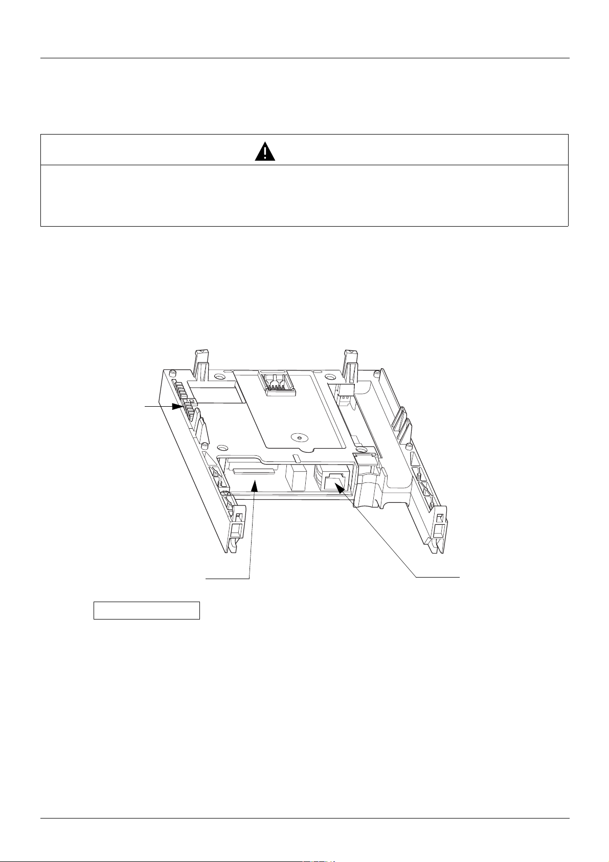
5. Hardware setup
LEDs
Shielded female RJ45
Ethernet connector
MAC address label
on the Ethernet card
00-80-F4-80-xx-yy
5. 1. Receipt
• Check that the card catalog number marked on the label is the same as that on the delivery note corresponding to the purchase order.
• Remove the option card from its packaging and check that it has not been damaged in transit.
CAUTION
STATIC SENSITIVE COMPONENTS
The Modbus TCP/IP Ethernet card can be damaged by static electricity. Observe electrostatic precautions when
handling and installing the card.
Failure to follow this instruction can result in equipment damage.
5. 2. Hardware description
5. 3. Installing the card in the drive
See the Installation Manual.
8 1755879 11/2009
Page 9
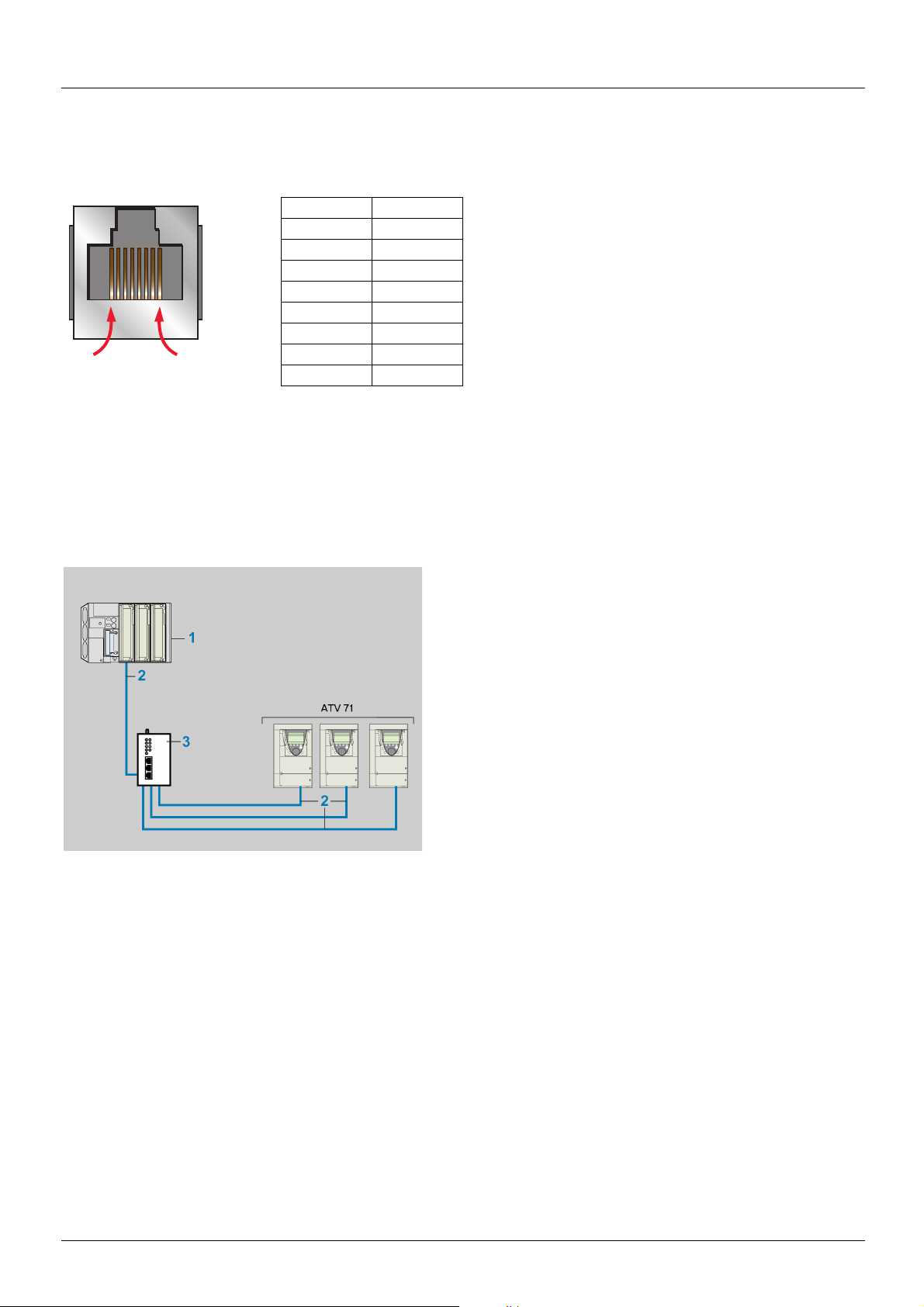
6. Connecting to the Ethernet network
8........................1
6. 1. Card RJ45 connector pinout
The Ethernet card is equipped with a shielded RJ45 connector. The shielding is connected to the drive ground.
Use an STP (shielded twisted pair) Ethernet cable.
Pin Signal
1TD+
2TD-
3 RD+
4
5
6 RD-
7
8
The transmission speed is detected automatically by the card (10 Mbps or 100 Mbps).
The card can operate in half duplex or full duplex mode, whether connected to a hub or a switch and regardless of the transmission speed
(10 Mbps or 100 Mbps).
The card supports the ETHERNET 2 frame format (IEEE 802-3 not supported).
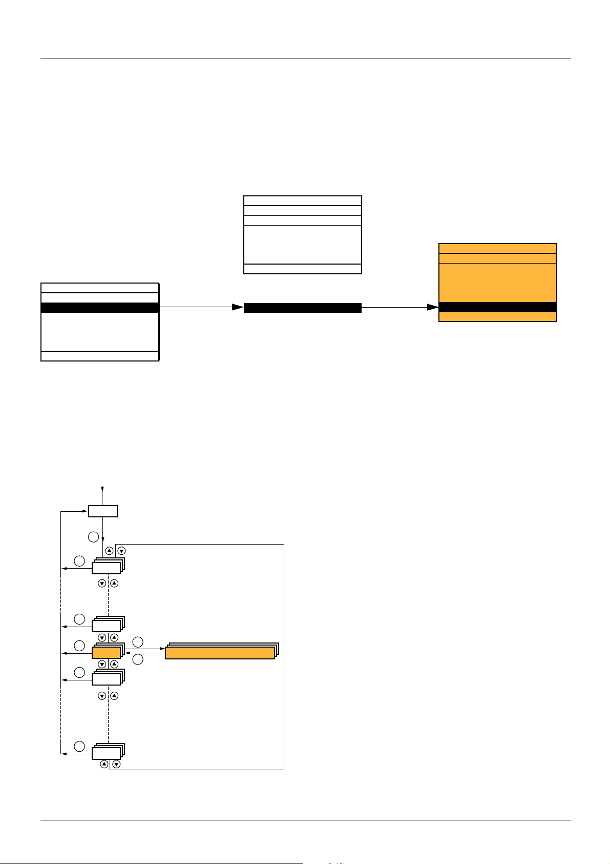
6. 2. Example of connection to an Ethernet network
1 TSX PREMIUM PLC with TSX ETY 4101 or 5101 module
2 490 NTW 000 02 cable
3 499 NEH 104 10 hub
1755879 11/2009 9
Page 10

6. Connecting to the Ethernet network
6. 3. Ethernet network connection elements
Please consult our catalog “Ethernet TCP/IP and the Web” (available on the Web site www.schneider-electric.com).
Connecting cables
Description Use Length Catalog number
From To m
Straight shielded twisted pair cables
2 RJ45 connectors
ATV71
(+ VW3 A3 310 card)
Hubs
pH 1pp 10
499 N
Switches
pS 171 00
499 N
Hubs and switches
Description Characteristics Catalog number
Hubs 4 × 10BASE-T ports 499 NEH 104 10
4 × 100BASE-TX ports 499 NEH 141 10
3 × 10BASE-T ports
2 × 10BASE-FL ports, multimode fiber, ST (BFOC) connectors
Switches 5 × 10BASE-T/100BASE-TX ports
Unmanageable basic
4 × 10BASE-T/100BASE-TX ports
1 × 100BASE-FX port, multimode fiber, SC connectors
Unmanageable
3 × 10BASE-T/100BASE-TX ports
2 × 100BASE-FX port, multimode fiber, SC connectors
Unmanageable
4 × 10BASE-T/100BASE-TX ports
1 × 100BASE-FX port, monomode fiber, SC connectors
Unmanageable
3 × 10BASE-T/100BASE-TX ports
2 × 100BASE-FX port, monomode fiber, SC connectors
Unmanageable
8 × 10BASE-T/100BASE-TX ports
Unmanageable
7 × 10BASE-T/100BASE-TX ports
Manageable
5 × 10BASE-T/100BASE-TX ports
2 × 100BASE-FX port, multimode fiber, SC connectors
Manageable
5 × 10BASE-T/100BASE-TX ports
2 × 100BASE-FX port, monomode fiber, SC connectors
Manageable
2 490 NTW 000 02
5 490 NTW 000 05
12 490 NTW 000 12
40 490 NTW 000 40
80 490 NTW 000 80
499 NOH 105 10
499 NES 251 00
499 NMS 251 01
499 NMS 251 02
499 NSS 251 01
499 NSS 251 02
499 NES 181 00
499 NES 271 00
499 NOS 271 00
499 NSS 271 00
10 1755879 11/2009
Page 11
7. Ethernet menu
RDY NET +0.00 Hz 0A
MAIN MENU
1 DRIVE MENU
2 ACCESS LEVEL
3 OPEN / SAVE AS
4 PASSWORD
5 LANGUAGE
Code Quick
ENT
RDY NET +0.00 Hz 0A
1 DRIVE MENU
1.1 SIMPLY START
1.2 MONITORING
1.3 SETTINGS
1.4 MOTOR CONTROL
1.5 INPUTS/OUTPUTS CFG
Code << >> Quick
1.6 COMMAND
1.7 APPLICATION FUNCT.
1.8 FAULT MANAGEMENT
1.9 COMMUNICATION
1.10 DIAGNOSTICS
1.11 IDENTIFICATION
1.12 FACTORY SETTINGS
1.13 USER MENU
1.14 PROGRAMMABLE CARD
ENT
RUN NET +50.00 Hz 80A
1.9 COMMUNICATION
COM. SCANNER OUTPUT
MODBUS HMI
MODBUS NETWORK
CANopen
ETHERNET
Code << >> Quick
XXX
SIM-
ESC
ESC
ENT
FCS-
LAC-
CON-
FLt-
ESC
ESC
ESC
ENT
ESC
Displays the drive state
COMMUNICATION
Power-up
7. 1. Access to Ethernet menu via graphic display terminal
The [ETHERNET] submenu is used to configure and display the Ethernet card parameters and can be accessed via the
[1.9 - COMMUNICATION] menu.
If you are using the FDR (Faulty Device Replacement) function, you must also configure the device name in the [7. DISPLAY CONFIG.]
menu, [7.1 USER PARAMETERS] submenu, [DEVICE NAME] submenu.
This menu is only accessible in expert mode: In the [2 ACCESS LEVEL] (LAC-) menu, set the level to [expert] (EPr).
7. 2. Access to Ethernet menu via the integrated display terminal
The (EtH-) submenu is used to configure and display the Ethernet card parameters. It can be accessed via the (COM-) menu.
Note: The device name required for the FDR (Faulty Device Replacement) function cannot be configured via the integrated display terminal.
1755879 11/2009 11
Page 12

7. Ethernet menu
7. 3. Ethernet menu parameters
Code Description
(bdr) M [Bit rate]
(PAn-)
(IPC-)
(IPC1)
(IPC2)
(IPC3)
(IPC4)
Transmission speed detected on the network by the Ethernet card
Type: Display (read-only)
Possible
values:
Default value: [0 Mbps] (0M)
b [DEVICE NAME]
Device name used by FDR service. Accessible with an ATV71 from V1.2 and a ATV61 from V1.3 version.
Use the navigation selector button to increment the character (alphabetical order) and << and >> (F2 and F3) to switch
to the next or previous character respectively. Use F1 to change to ABC, abc, 123, *[-.
Type: Configuration (read and write)
Possible values: 16 characters on 1 or 2 lines.
Default value: [0]
b [IP card]
M [139.160.069.241] (139) (160) (069) (241)
Ethernet card IP address
Type: Configuration (read and write)
Possible
values:
Default value: [0.0.0.0] (0) (0) (0) (0)
[0 Mbps] (0M): Indeterminate speed (before automatic detection of the Ethernet network speed)
[10 Mbps] (10M): 10 Mbps
[100 Mbps] (100M): 100 Mbps
Display (read-only)
Display (read-only) if the address has been supplied by a BOOTP or DHCP server
• 0 to 255 for each of fields IPC1, IPC2, IPC3 and IPC4.
• If the value is [0.0.0.0] (0) (0) (0) (0), the Ethernet card waits for an address from a BOOTP
or DHCP server.
Note: If you enter a value other than [0.0.0.0] (0) (0) (0) (0), dynamic addressing by a BOOTP
or DHCP server is disabled.
Note: After dynamic addressing by a BOOTP or DHCP server, the value [0.0.0.0] (0)(0)(0)(0)
is replaced by the address supplied.
(IPM-)
(IPM1)
(IPM2)
(IPM3)
(IPM4)
(IPG-)
(IPG1)
(IPG2)
(IPG3)
(IPG4)
b [IP Mask]
M [255.255.254.0] (255) (255) (254) (0)
Subnet mask
Type: Configuration (read and write)
Possible
values:
Default value: [0.0.0.0] (0) (0) (0) (0)
Display (read-only) if the address has been supplied by a BOOTP or DHCP server
• 0 to 255 for each of fields IPM1, IPM2, IPM3 and IPM4.
• If the value of the IP address [IP card] is [0.0.0.0] (0) (0) (0) (0), the Ethernet card waits for
a mask from a BOOTP or DHCP server.
Note: After dynamic addressing by a BOOTP or DHCP server, the current value is replaced by the
address supplied.
b [IP Gate]
M [0.0.0.0] (0) (0) (0) (0)
Gateway IP address
Type: Configuration (read and write)
Possible
values:
Default value: [0.0.0.0] (0) (0) (0) (0)
Display (read-only) if the address has been supplied by a BOOTP or DHCP server
• 0 to 255 for each of fields IPG1, IPG2, IPG3 and IPG4.
• If the value of the IP address [IP card] is [0.0.0.0] (0) (0) (0) (0), the Ethernet card waits for
a mask from a BOOTP or DHCP server.
Note: After dynamic addressing by a BOOTP or DHCP server, the current value is replaced by the
address supplied.
12 1755879 11/2009
Page 13

7. Ethernet menu
Code Description
(IPP-)
(IPP1)
(IPP2)
(IPP3)
(IPP4)
(IPF-)
(IPF1)
(IPF2)
(IPF3)
(IPF4)
(ISA) M [IO Scan.activ.]
(tOUt) M [time out]
b [IP Master]
M [0.0.0.0] (0) (0) (0) (0)
IP address of the device that retains control
Type: Configuration (read and write)
Possible
values:
Default value: [0.0.0.0] (0) (0) (0) (0)
b [IP FDR]
M [0.0.0.0] (0) (0) (0) (0)
IP address of the FDR server
Type: Display (read-only)
Possible
values:
Default value: [0.0.0.0] (0) (0) (0) (0)
Enable IO Scanner
Type: Configuration (read and write)
Possible
values:
Default value: [Yes] (YES)
Display (read-only) if the address is supplied by a DHCP server
• 0 to 255 for each of fields IPP1, IPP2, IPP3 and IPP4.
• If the value is [0.0.0.0] (0) (0) (0) (0), writing of the control word (CMd) is accepted
by the Ethernet card regardless of which device has sent it.
• If the value is other than [0.0.0.0] (0) (0) (0) (0) only the device which has the IP address
[IP Master] is authorized to write the control word (CMd).
Note: This configuration also affects the type of communication monitoring.
• 0 to 255 for each of fields IPF1, IPF2, IPF3 and IPF4.
• If the value is [0.0.0.0] (0) (0) (0) (0), there is no server.
• [No] (nO): IO Scanner disabled.
• [Yes] (YES): IO Scanner enabled.
Ethernet communication monitoring time out
Type: Configuration (read and write)
Possible
values:
Default value: [2.0 s] (2.0)
(FdrU) M [FDR validation]
Enable FDR service
Type: Configuration (read and write)
Possible
values:
Default value: [Yes] (YES)
(LCFG) M [FDR Local Config.]
Selection of local or server configuration
Type: Configuration (read and write)
Possible
values:
Default value: [No] (nO)
(FdrF) M [FDR Error Mgt.]
Enable FDR fault management process
Type: Configuration (read and write)
Possible
values:
Default value: [Yes] (YES)
• [0] (0): Monitoring disabled.
• [0.5 s] (0.5) to [60.0 s] (60.0): Time out value (unit: 0.1 s).
• [No] (nO): FDR service disabled.
• [Yes] (YES): FDR service enabled.
• [No] (nO): The drive configuration is downloaded from an FDR server.
• [Yes] (YES): The drive configuration is local and saved in a FDR server.
In the event of a problem with the FDR file (missing or invalid):
• [No] (nO): The Ethernet card does not trigger an Ethernet fault (network management).
• [Yes] (YES): The Ethernet card triggers a network management fault.
1755879 11/2009 13
Page 14

7. Ethernet menu
Code Description
(FdrA) M [FDR Action]
FDR service command
Type: Command (read and write)
Possible
values:
Default value: [IDLE] (IdLE)
(FdrS) M [FDR autosave]
Enable periodic saving of the FDR service
Type: Configuration (read and write)
Possible
values:
Default value: [No] (nO)
(Fdrt) M [FDR t.autosave]
Interval for periodic saving of the FDR service
Type: Configuration (read and write)
Possible
values:
Default value: [10] (10)
(FdrE) M [FDR state]
• [IDLE] (IdLE): No command.
• [SAVE] (SAUE): Command: save.
• [REST] (rESt): Command: download.
• [DEL] (dEL): Command: delete.
The command remains displayed during the action then reverts to the value [IDLE] (IdLE).
• [No] (nO): Automatic saving disabled.
• [Yes] (YES): Automatic saving enabled.
• [2] (2) to [9999] (9999): 2 min to 9999 min.
FDR service state
Type: Display (read-only)
Possible
values:
Default value: [IDLE] (IdLE)
(Fdrd) M [FDR Error Code]
FDR service error code
Type: Display (read-only)
Possible
values:
Default value: [0] (0)
• [IDLE] (IdLE): “Idle”.
• [INIT] (INIt): Initialization.
• [CONF] (CONF): Configuration.
• [RDY] (rdY): Ready.
• [GET] (GEt): Download the current configuration.
• [SET] (SEt): Save the current configuration.
• [APP] (APP): Write the FDR server configuration to the drive.
• [OPE] (OPE): Operational.
• [UCFG] (UCFG): Not configured.
• [0] (0): No fault.
• [2] (2): The FDR configuration file is not compatible with the drive type
(example: the drive is not the same rating as that defined in the FDR file).
• [3] (3): Error reading the FDR configuration file on the server.
• [4] (4): Error writing the FDR configuration file to the server.
• [7] (7): Time-out for receipt of the FDR configuration file from the server.
• [9] (9): Duplication of IP address.
• [12] (12): The FDR configuration file is missing.
14 1755879 11/2009
Page 15

8. Configuration
8. 1. List of functions to be configured
The table below gives the list of configuration functions and how they can be accessed:
Functions
Entering the IP addresses ppp
FDR
(Faulty Device Replacement)
IO Scanning
Reserving control (IP master) pppp
Communication monitoring pppp
Security of access
to the standard Web server
Configuration using the drive graphic display terminal or the integrated display terminal is explained in the “Configuration” section.
Configuration using the standard Web server is explained in the “Standard Web server” section.
For configuration using the PowerSuite software workshop, refer to the online help.
Note: The Ethernet card saves its configuration (IP address, mask, gateway, etc.) to the EEPROM each time the configuration is modified.
Note: For performance reasons, we do not recommend using the drive communication scanner. It is better to use the Ethernet IO Scanner.
Note: Configuration must be performed with the motor stopped.
Entering the device name pp
Configuration (time delay, etc.) pppp
Commands (save, etc.) pp p
Enable IO Scanner pppp
Configuring the IO Scanner variables pp
Changing the “username” p
Changing the “HTTP password” p
Changing the “Write password” pp
Graphic
display
terminal
Integrated
display
terminal
PowerSuite
software
workshop
Standard
Web
server
1755879 11/2009 15
Page 16
8. Configuration
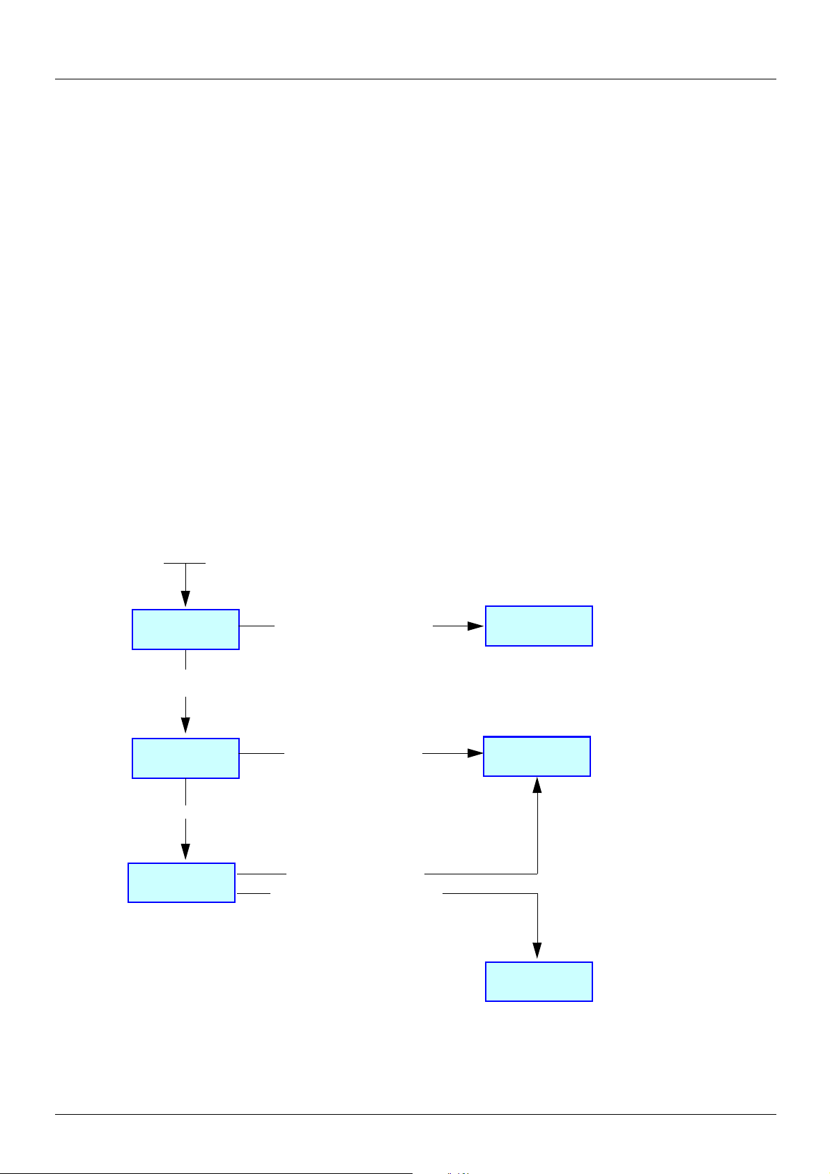
Static
addressing
DHCP
FDR
BOOTP
Initialization
Power-up
An address has been entered
[IP card] <> 0.0.0.0
No address has been entered
[IP card] = 0.0.0.0
Dynamic
addressing
[FDR validation] = [No]
[FDR validation] = [Yes]
[DEVICE NAME] blank
[DEVICE NAME] has been
entered
8. 2. Configuring IP addresses
b Assigning IP addresses
The drive needs 3 IP addresses:
• The drive IP address.
• The subnet mask.
• The gateway IP address.
These IP addresses can be entered directly:
• Using the integrated display terminal.
• Using the graphic display terminal.
• Or using the PowerSuite software workshop.
They can be provided by:
• A BOOTP server (correspondence between the MAC address and the IP addresses).
• Or a DHCP server (correspondence between Device Name [DEVICE NAME] and the IP addresses).
If an IP address other than 0.0.0.0 has been entered using the display terminal or the PowerSuite software workshop, assignment using
a server is disabled.
The BOOTP service is enabled:
• When no IP address other than 0.0.0.0 has been entered.
• And the FDR service has not been enabled ([FDR validation] parameter = [No] or a [DEVICE NAME] has not been entered).
The DHCP service is enabled:
• When no IP address other than 0.0.0.0 has been entered.
• And the FDR service has been enabled ([FDR validation] parameter = [Yes] and a [DEVICE NAME] has been entered).
16 1755879 11/2009
Page 17

8. Configuration
b Entering IP addresses in the terminal
In the [1.9 - COMMUNICATION] (COM-) menu, [ETHERNET] (EtH-) submenu, enter the following IP addresses:
- [IP card] (IPC1) (IPC2) (IPC3) (IPC4).
- [IP Mask] (IPM1) (IPM2) (IPM3) (IPM4).
- [IP Gate] (IPG1) (IPG2) (IPG3) (IPG4).
Turn the drive off and then back on again (control voltage if a separate power supply is being used), otherwise the IP addresses are not
taken into account.
Note: Before entry begins, the IP address displayed is the active IP address.
If this address is modified, the new IP address entered is displayed. This IP address will be effective the next time the drive is turned on.
b Configuring BOOTP
The BOOTP service is used to assign IP addresses from the MAC address. The MAC address consisting of 6 hexadecimal digits
(00-80-F4-80-xx-yy) must be entered in the BOOTP server. The MAC address appears on the label attached to the Ethernet card.
In the [1.9 - COMMUNICATION] (COM-) menu, [ETHERNET] (EtH-) submenu:
• Leave the IP address [IP card] (IPC1) (IPC2) (IPC3) (IPC4) at the value [0.0.0.0] (0) (0) (0) (0).
• Do not enable the FDR service: [FDR validation] (FdrU) = [No] (nO).
b Configuring FDR
The FDR service (based on DHCP) is used to assign the IP addresses from the device name that must be entered in the drive and in the
FDR server (DHCP).
In the [1.9 - COMMUNICATION] (COM-) menu, [ETHERNET] (EtH-) submenu:
• Leave the IP address [IP card] (IPC1) (IPC2) (IPC3) (IPC4) at the value [0.0.0.0] (0) (0) (0) (0).
• Enable the FDR service: [FDR validation] (FdrU) = [Yes] (YES).
For the FDR function, select the drive configuration as either:
•Local: [FDR Local Config.] (LCFG) = [Yes] (YES).
• Downloaded. In this case, it is essential to consult the “FDR Service” section.
Enter the device name, [DEVICE NAME], in the [7. DISPLAY CONFIG.] menu, [7.1 USER PARAMETERS] submenu.
This menu is only accessible in expert mode: In the [2 ACCESS LEVEL] (LAC-) menu, set the level to [expert] (EPr).
Turn the drive off and then back on again (control voltage if a separate power supply is being used), otherwise the device name is not taken
into account.
Note: The FDR function cannot be fully configured using the integrated display terminal as it does not provide access to the device name.
1755879 11/2009 17
Page 18

8. Configuration
8. 3. Reserving control
It is strongly recommended that control should be reserved for a single master device.
If control were not to be reserved for a master device (for example a PLC):
• Any other Modbus TCP Ethernet client could send unwanted commands.
• Other clients could use the 8 available TCP connections and prevent the master from having control.
WARNING
IP MASTER NOT SPECIFIED
Use the [IP MASTER] (IPP) menu option to configure a network master device. If a valid IP address for a master device is not specified
using this option, other Ethernet clients can saturate the TCP connections or send incorrect commands leading to unintended equipment
operation.
Failure to follow this instruction can result in death, serious injury, or equipment damage.
To configure this reservation, enter an IP address other than [0.0.0.0] (0) (0) (0) (0) in the [1.9 COMMUNICATION] (COM-) menu,
[ETHERNET] (EtH-) submenu, [IP Master] submenu.
• If control has been reserved:
Only the control word (CMd) written by the master with control will be accepted via IO Scanning or via Modbus TCP messaging.
2 TCP connections are reserved for this device. In this way, you avoid other TCP clients using all the available connections
(8 maximum) and the control master therefore no longer being able to access the drive Modbus TCP server.
Other parameters written from other IP addresses are accepted (for example, adjustments or writing a setpoint).
When control has been reserved and another device attempts to write the control word (CMd):
- via IO Scanning: The Modbus TCP connection for this client is immediately reinitialized.
- via Modbus TCP messaging: Control is denied.
• If control has not been reserved ([IP Master] = [0.0.0.0] (0) (0) (0) (0)), control can come from any IP address.
8. 4. Configuring IO Scanning
Refer to the “IO Scanning Service” section.
The drive IO Scanning service can be enabled or disabled in the [1.9 - COMMUNICATION] (COM-) menu, [ETHERNET] (EtH-)
submenu via parameter [IO Scan.activ.] (IOSA).
It is not possible to modify the assignment of the IO Scanning periodic variables using the display terminal (integrated or graphic).
To configure IO Scanning, use the standard Web server or the PowerSuite software workshop.
18 1755879 11/2009
Page 19

8. Configuration
8. 5. Configuring the control
Numerous configurations are possible. For more information, refer to the Programming Manual and the Communication parameters
Manual.
The following configurations are just some of the possibilities available.
b Control via Ethernet in I/O profile
The command and setpoint come from Ethernet.
The command is in I/O profile.
Configure the following parameters:
Parameter Value Comment
Profile I/O profile The run command is simply obtained by bit 0 of the control word.
Setpoint 1 configuration Network card The setpoint comes from Ethernet.
Command 1 configuration Network card The command comes from Ethernet.
Configuration via the graphic display terminal or the integrated display terminal:
Menu Parameter Value
[1.6 - COMMAND] (CtL-) [Profile] (CHCF) [I/O profile] (IO)
[Ref.1 channel] (Fr1) [Com. card] (nEt)
[Cmd channel 1] (Cd1) [Com. opt card] (nEt)
b Control via Ethernet or the terminals in I/O profile
Both the command and setpoint come from Ethernet or the terminals. Input LI5 at the terminals is used to switch between Ethernet
and the terminals.
The command is in I/O profile.
Configure the following parameters:
Parameter Value Comment
Profile I/O profile The run command is simply obtained by bit 0 of the control word.
Setpoint 1 configuration Network card Setpoint 1 comes from Ethernet.
Setpoint 1B configuration Analog input 1 on the terminals Setpoint 1B comes from input AI1 on the terminals.
Setpoint switching Input LI5 Input LI5 switches the setpoint (1
Command 1 configuration Network card Command 1 comes from Ethernet.
Command 2 configuration Terminals Command 2 comes from the terminals.
Command switching Input LI5 Input LI5 switches the command.
Note: Setpoint 1B is connected to the functions (summing, PID, etc.), which remain active, even after switching.
Configuration via the graphic display terminal or the integrated display terminal:
Menu Parameter Value
[1.6 - COMMAND] (CtL-) [Profile] (CHCF) [I/O profile] (IO)
[Ref.1 channel] (Fr1) [Com. card] (nEt)
[Cmd channel 1] (Cd1) [Com. card] (nEt)
[Cmd channel 2] (Cd2) [Terminals] (tEr)
[Cmd switching] (CCS) [LI5] (LI5)
[1.7 APPLICATION FUNCT.] (FUn-)
[REFERENCE SWITCH.]
[Ref.1B channel] (Fr1b) [Ref. AI1] (AI1)
[Ref 1B switching] (rCb) [LI5] (LI5)
↔1B).
1755879 11/2009 19
Page 20

8. Configuration
b Control via Ethernet in Drivecom profile
The command and setpoint come from Ethernet.
The command is in Drivecom profile.
Configure the following parameters:
Parameter Value Comment
Profile Drivecom profile not
separate
Setpoint 1 configuration Network card The command comes from Ethernet.
Configuration via the graphic display terminal or the integrated display terminal:
Menu Parameter Value
[1.6 - COMMAND] (CtL-) [Profile] (CHCF) [Not separ.] (SIM) (factory setting)
[Ref.1 channel] (Fr1) [Com. card] (nEt)
b Control via Ethernet or the terminals in Drivecom profile
Both the command and setpoint come from Ethernet or the terminals. Input LI5 at the terminals is used to switch between Ethernet
and the terminals.
The command is in Drivecom profile.
The run commands are in Drivecom profile, the command and the setpoint
come from the same channel.
Configure the following parameters:
Parameter Value Comment
Profile Drivecom profile not separate The run commands are in Drivecom profile, the command and the
Setpoint 1 configuration Network card Setpoint 1 comes from Ethernet.
Setpoint 2 configuration Analog input 1 on the terminals Setpoint 2 comes from input AI1 on the terminals.
Setpoint switching Input LI5 Input LI5 switches the setpoint (1
Note: Setpoint 2 is directly connected to the drive setpoint limit. If switching is performed, the functions that affect the setpoint (summing,
PID, etc.) are disabled.
Configuration via the graphic display terminal or the integrated display terminal:
Menu Parameter Value
[1.6 - COMMAND] (CtL-) [Profile] (CHCF) [Not separ.] (SIM)
[Ref.1 channel] (Fr1) [Com. card] (nEt)
[Ref.2 chan] (Fr2) [Ref. AI1] (AI1)
[Ref. 2 switching] (rFC) [LI5] (LI5)
setpoint come from the same channel.
↔ 2) and the command.
20 1755879 11/2009
Page 21

8. Configuration
b Command in Drivecom profile via Ethernet and setpoint switching at the terminals
The command comes from Ethernet.
The setpoint comes either from Ethernet or from the terminals. Input LI5 at the terminals is used to switch the setpoint between Ethernet
and the terminals.
The command is in Drivecom profile.
Configure the following parameters:
Parameter Value Comment
Profile Drivecom profile separate The run commands are in Drivecom profile, the command and the
Setpoint 1 configuration Network card Setpoint 1 comes from Ethernet.
Setpoint 1B configuration Analog input 1 on the terminals Setpoint 1B comes from input AI1 on the terminals.
Setpoint switching Input LI5 Input LI5 switches the setpoint (1
Command 1 configuration Network card Command 1 comes from Ethernet.
Command switching Channel 1 Channel 1 is the command channel.
Note: Setpoint 1B is connected to the functions (summing, PID, etc.), which remain active, even after switching.
Configuration via the graphic display terminal or the integrated display terminal:
setpoint can come from different channels.
↔1B).
Menu Parameter Value
[1.6 - COMMAND] (CtL-) [Profile] (CHCF) [Separate] (SEP)
[Ref.1 channel] (Fr1) [Com. card] (nEt)
[Cmd channel 1] (Cd1) [Com. card] (nEt)
[Cmd switching] (CCS) [Ch1 active] (Cd1)
[1.7 APPLICATION FUNCT.] (FUn-)
[REFERENCE SWITCH.]
[Ref.1B channel] (Fr1b) [Ref. AI1] (AI1)
[Ref 1B switching] (rCb) [LI5] (LI5)
1755879 11/2009 21
Page 22

8. Configuration
8. 6. Configuring the fault management
b Communication monitoring
The Ethernet card can detect 2 types of fault:
- Network management faults (server missing, duplication of IP address, etc.).
- Communication faults (time out on the master traffic, etc.).
The associated information is:
Network management Communication
Associated drive fault Code:
Configuring the
communication fault
Configuring the drive’s
response
[External fault com.] (EPF2)
Parameter:
[FDR Error Mgt.] (FdrF)
Menu:
[1.9 COMMUNICATION] (COM-)
Submenu:
[ETHERNET] (EtH-)
Parameter:
[External fault mgt] (EPL)
Menu:
[1.8 FAULT MANAGEMENT] (FLt-)
Submenu:
[EXTERNAL FAULT] (EtF-)
Ethernet fault type
Code:
[Com. network] (CnF)
Parameter:
[time Out] (tOUt)
Menu:
[1.9 COMMUNICATION] (COM-)
Submenu:
[ETHERNET] (EtH-)
Parameter:
[COM. fault mgt] (CLL)
Menu:
[1.8 FAULT MANAGEMENT] (FLt-)
Submenu:
[COM. FAULT MANAGEMENT] (CLL-)
b Network management fault
The IP address duplication management fault cannot be configured.
If the FDR (Faulty Device Replacement) service has been configured, the FDR fault can be disabled via the [FDR Error Mgt.] (FdrF)
parameter, which can be accessed via the [1.9 COMMUNICATION] (COM-) menu, [ETHERNET] (EtH-) submenu.
In factory settings mode, a network management fault will trigger a resettable drive fault [External fault com.] (EPF2) and initiate
a freewheel stop.
b Communication fault
It is strongly recommended that control should be reserved for a single master device.
Monitoring begins when the first control word is received.
WARNING
IP MASTER NOT SPECIFIED
Use the [IP MASTER] (IPP) menu option to configure a network master device. If a valid IP address for a master device is not specified
using this option, other Ethernet clients can saturate the TCP connections or send incorrect commands leading to unintended equipment
operation.
Failure to follow this instruction can result in death, serious injury, or equipment damage.
• If control has been reserved:
A communication fault is triggered if the Ethernet card does not receive a Modbus TCP request within a predefined period
of time (time out).
Any type of Modbus request from the master device [IP Master] is taken into account (write operation, read operation, etc.).
• If control has not been reserved:
A communication fault is triggered if the Ethernet card does not receive a control word write request (CMd) within a predefined
period of time (time out).
Receipt of the command (CMd) is taken into account regardless of the sender’s IP address.
The “time out” can be set to between 0.5 and 60 s via the graphic display terminal or integrated display terminal in the
[1.9 COMMUNICATION] (COM-) menu, [ETHERNET] (EtH-) submenu via the [time Out] (tOUt) parameter. The default value is 2 s.
In factory settings mode, if Ethernet is involved in the command or setpoint, a communication fault will trigger a resettable drive fault
[Com. network] (CnF) and initiate a freewheel stop.
22 1755879 11/2009
Page 23
8. Configuration
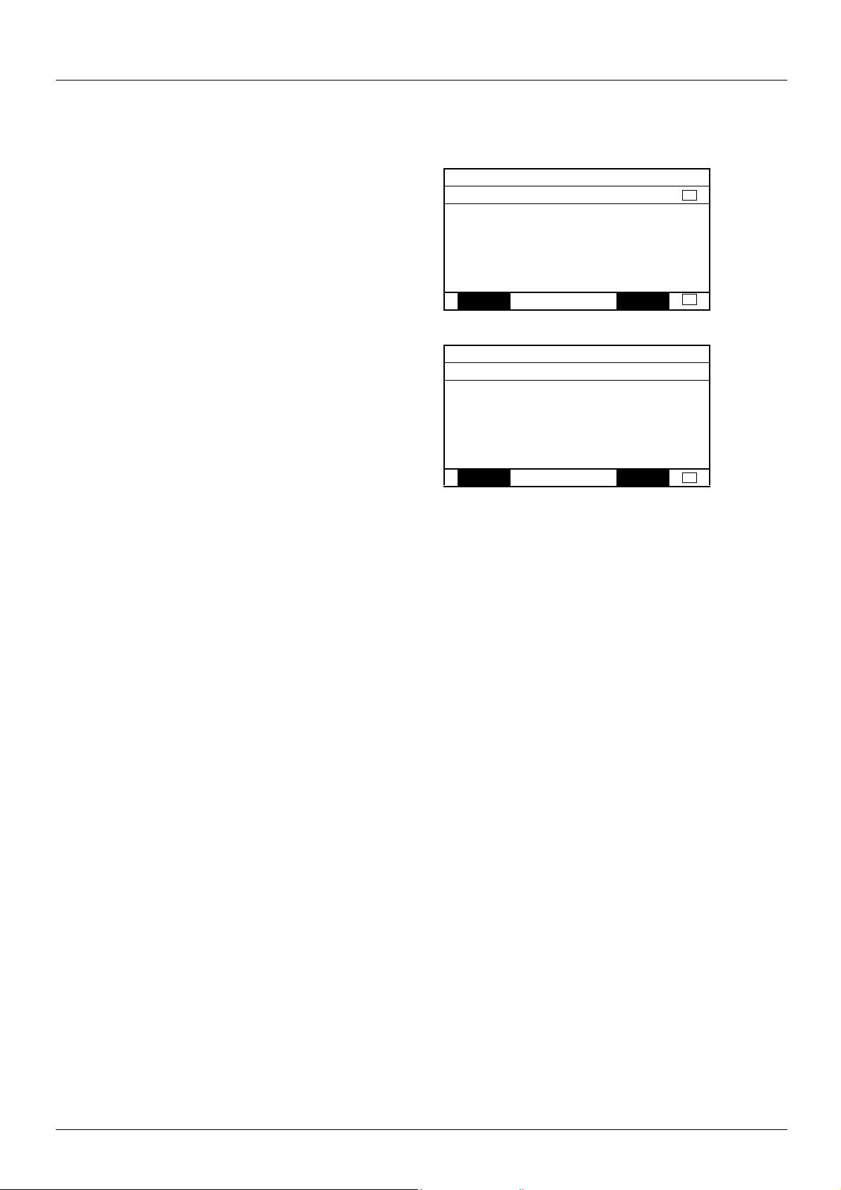
RDY NET +0.00Hz 0A
COM. FAULT MANAGEMENT
Network fault mgt : Freewheel
CANopen fault mgt : Freewheel
Modbus fault mgt : Freewheel
Code Quick
RDY NET +0.00Hz 0A
EXTERNAL FAULT
External fault mgt : Freewheel
Code Quick
For communication faults
in the [COM. FAULT MANAGEMENT] (CLL-) submenu
via parameter [COM. fault mgt] (CLL)
For network management faults
in the [EXTERNAL FAULT] (EtF-) submenu
via the [External fault mgt] (EPL) parameter
b Drive response
The drive response to an Ethernet fault can be configured via the graphic display terminal or the integrated display terminal,
from the [1.8 FAULT MANAGEMENT] (FLt-) menu:
The values of parameters: [COM. fault mgt] (CLL) that will trigger a drive fault [Com. network] (CnF)
and [External fault mgt] (EPL) that will trigger a drive fault [External fault com.] (EPF2) are:
[Freewheel] (YES): Freewheel stop (factory setting).
[Ramp stop] (rMP): Stop on ramp.
[Fast stop] (FSt): Fast stop.
[DC injection] (dCI): DC injection stop.
The values of parameters [COM. fault mgt] (CLL) and [External fault management] (EPL) which will not trigger a drive fault are:
[Ignore] (nO): Fault ignored.
[Per STT] (Stt): Stop according to configuration of [Stop type] (Stt).
[fallback spd] (LFF): Change to fallback speed, maintained as long as the fault persists and the run command has not been removed.
[Spd maint.] (rLS): The drive maintains the speed at the time the fault occurred, as long as the fault persists and the run command has
not been removed.
The fallback speed can be configured in the
[1.8 - FAULT MANAGEMENT] (FLt-) menu via the [Fallback speed] (LLF) parameter.
1755879 11/2009 23
Page 24

8. Configuration
8. 7. Configuring monitored parameters
It is possible to select up to 4 parameters to display their values in the [1.2 - MONITORING] menu on the graphic display terminal.
The selection is made via the [6 - MONITORING CONFIG.] menu, [6.3 - COM. MAP CONFIG.] submenu.
Each parameter in the range [Address 1 select.] … [Address 4 select.]
is used to select the parameter logic address. Select an address of zero
to disable the function.
In the example given here, the monitored words are:
• Parameter 1 = Motor current (LCR): logic address 3204;
signed decimal format.
• Parameter 2 = Motor torque (OTR): logic address 3205;
signed decimal format.
• Parameter 3 = Last fault occurred (LFT): logic address 7121;
hexadecimal format.
• Disabled parameter: address 0; default format: hexadecimal format.
One of the three display formats below can be assigned to each monitored word:
Format Range Terminal display
Hexadecimal 0000 … FFFF [Hex]
Signed decimal -32,767 … 32,767 [Signed]
Unsigned decimal 0 … 65,535 [Unsigned]
RDY NET +0.00Hz 0A
6.3 COM. MAP CONFIG.
Word 1 add. select. : 3204
Format word 1 : Signed
Word 2 add. select. : 3205
Format word 2 : Signed
Word 3 add. select. : 7121
Code Quick
Format word 33 : Hex
Word 4 add. select. : 0
Format word 4 : Hex
24 1755879 11/2009
Page 25

9. Diagnostics
1.1
1.2
1.3
1.4
1.5
2.1
2.2
2.3
2.4
2.5
RX - Reception
TX - Transmission
FLT - Ethernet fault
STS - Communication status
10/100 - 10/100 Mbps
9. 1. Signalling LEDs
The VW3 A3 310 Ethernet card features 5 LEDs, which are visible through the Altivar 71 cover.
The following table gives the meaning of the various states of these LEDs.
No. Code Color State Meaning
2.1 RX Yellow On Receipt of a frame by the Ethernet card.
2.2 TX Yellow On Transmission of a frame by the Ethernet card.
2.3 FLT Red
2.4 STS Green
2.5 10/100 Green
Off No Ethernet fault.
On Ethernet fault present.
Off No IP address entered, or assigned by a BOOTP or FDR (DHCP) server.
On IP address properly configured and Ethernet card connected.
3 flashes: The card is not connected. Corrective action: Check the network wiring.
4 flashes: Another device has
Flashing
5 flashes: Dynamic addressing
Off 10 Mbps or no speed detected.
On 100 Mbps.
the same IP address
as the drive.
is active.
Corrective action: Disconnect one of the devices involved
or modify its IP address, then restart the drive.
Corrective action: If this state lasts too long, check the IP
address server.
9. 2. Available information
In addition to the LEDs, the table below summarizes the diagnostic information available by various means.
Functions Graphic display
Control-signal diagnostics
• Control word
• Setpoint
• Active channel
•Etc.
Communication diagnostics
• Transmission counter
• Reception counter
• Collision counter
•Etc.
1755879 11/2009 25
terminal
Integrated display
terminal
PowerSuite software
workshop
Standard
Web server
pppp
pp
Page 26

9. Diagnostics
RUN NET +50.00 Hz 80A
COMMUNICATION MAP
Command Channel : Com. card
Cmd value : 000F
Hex
Channel ref. active : Com. card
Frequency ref. : 500.0
Hz
Status word : 8627
Hex
Code Quick
W3204 : 53
W3205 : 725
W7132 : 0000
Hex
W0 : -----
Hex
COM. SCANNER INPUT MAP
COM SCAN OUTPUT MAP
CMD. WORD IMAGE
FREQ. REF. WORD MAP
MODBUS NETWORK DIAG
MODBUS HMI DIAG
CANopen MAP
SCANNER CARD PROG.
Active command channel
Value of control word used
to send a command to the drive
(hexadecimal format)
Active setpoint channel
Value of frequency setpoint
(unit 0.1 Hz) used to control the drive
Value of status word
(hexadecimal format)
Values of the four monitored words selected by the user.
The address and display format of these parameters
can be configured in the [6 - MONITORING CONFIG.] menu,
[6.3 - COM. MAP CONFIG.] submenu
(see “Configuration” section on page 15
).
The value of a monitored word is equal to “-----” if:
- Monitoring has not been activated
(address equal to W0)
- The parameter is protected
- The parameter is not known (e.g., W3200)
Communication scanner:
use not recommended for Ethernet
Control word from Ethernet
[COM. card cmd.] (CMd3)
Frequency setpoint from Ethernet
[Com. card ref.] (LFr3)
9. 3. Monitoring the control
On the graphic display terminal only, the [1.2 - MONITORING] menu, [COMMUNICATION MAP] submenu can be used to display
control-signal diagnostic information between the drive and the Ethernet PLC:
26 1755879 11/2009
Page 27

9. Diagnostics
9. 4. Troubleshooting the communication fault
b Communication monitoring
Ethernet faults are indicated by the red FLT LED on the Ethernet card.
The Ethernet card can detect 2 types of fault:
- Network management faults (server missing, duplication of IP address, etc.).
- Communication faults (time out on the master traffic, etc.).
In factory settings mode, a network management fault will trigger a resettable drive fault [External fault com.] (EPF2) and initiate
a freewheel stop.
In factory settings mode, if Ethernet is involved in the command or setpoint, a communication fault will trigger a resettable drive fault
[Com. network] (CnF) and initiate a freewheel stop.
The drive’s response in the event of an Ethernet communication fault can be changed (see the Configuration section).
- Drive fault [Com. network] (CnF) or [External fault com.] (EPF2) (freewheel stop, stop on ramp, fast stop or DC
injection braking stop).
- No drive fault (stop, maintain, fallback).
The associated information is:
Ethernet communication fault type
Network management Communication
Associated drive fault Code:
[External fault com.] (EPF2)
Extended fault code [FDR fault] (Fdrd)
Menu:
[1.9 COMMUNICATION] (COM-)
Submenu:
[ETHERNET] (EtH-)
Code:
[Com. network] (CnF)
[Network fault] (CnF)
Menu:
[1.10 DIAGNOSTICS] (dGt-)
Submenu:
[MORE FAULT INFO] (AFI-)
Parameter [Network fault] (CnF) is used to obtain more detailed information about the origin of the last fault [Com. network] (CnF). It can
be accessed on the graphic display terminal only, in the [1.10 DIAGNOSTICS] (dGt-) menu, [MORE FAULT INFO] (AFI-) submenu.
Value Description of the values of the [Network fault] (CnF) parameter
0No fault
1 Modbus TCP time out
10 Network overload
11 Loss of Ethernet carrier
The [FDR fault] (Fdrd) Ethernet fault parameter is used to obtain more detailed information about the origin of the last fault
[External fault com.] (EPF2). It can be accessed on the graphic display terminal only, in the [1.9 COMMUNICATION] (COM-) menu,
[ETHERNET] (EtH-) submenu.
Value Description of the values of the [FDR fault] (Fdrd) Ethernet fault code parameter
0 No fault.
2 The FDR configuration file is not compatible with the drive type (example: the drive is not the correct rating).
3 Error reading the FDR configuration file on the server.
4 Error writing the FDR configuration file to the server.
7 Time-out for receipt of the FDR configuration file from the server.
9 Duplication of IP address (1).
12 FDR configuration file missing.
(1)The Ethernet card detects IP address duplication each time it connects to the network (power-up or connection to the network).
If the card detects that another device is using the same IP address as itself, it abandons the use of the IP address and triggers a fault
[External fault com.] (EPF2).
If a device with an IP address identical to that of the drive is connected to the network during operation, the drive does not detect a fault
(it is the new station that has to disconnect).
1755879 11/2009 27
Page 28

9. Diagnostics
9. 5. Troubleshooting the card fault
The [internal com. link] (ILF) fault appears when the following serious problems occur:
- Hardware fault on the Ethernet card.
- Dialog fault between the Ethernet card and the drive.
The drive’s response in the event of an [internal com. link] (ILF) fault cannot be configured, and the drive trips with a freewheel stop.
This fault cannot be reset.
Two diagnostic parameters are used to obtain more detailed information about the origin of the [internal com. link] (ILF) fault:
- [Internal link fault 1] (ILF1) if the fault has occurred on option card no. 1 (installed directly on the drive).
- [Internal link fault 2] (ILF2) if the fault has occurred on option card no. 2 (installed on option card no. 1).
The Ethernet card can be in position 1 or 2.
The [Internal link fault 1] (ILF1) and [Internal link fault 2] (ILF2) parameters can only be accessed on the graphic display terminal
in the [1.10 DIAGNOSTICS] (dGt-) menu, [MORE FAULT INFO] (AFI-) submenu.
Value Description of the values of the [Internal link fault 1] (ILF1) and [Internal link fault 2] (ILF2) parameters
0 No fault
1 Loss of internal communication with the drive
3 Error in the EEPROM checksum
101 Unknown card
102 Exchange problem on the drive internal bus
103 Time out on the drive internal bus (500 ms)
28 1755879 11/2009
Page 29

10. Software setup
10. 1. List of services supported
• Modbus TCP server, with the support of the “IO Scanning” periodic service.
• IP protocol (version 4).
• TCP and UDP protocol.
• HTTP server for configuring, adjusting and monitoring the drive.
• ICMP client for supporting certain IP services, such as the “ping” command.
• BOOTP client for assignment of an IP address by an address server.
• FTP protocol for file transfer.
• DHCP client for dynamic assignment of IP addresses by an address server.
• FDR service for replacement of a faulty device.
• SNMP protocol for network management.
• ARP protocol for detecting a competing IP address (IP address already in use).
10. 2. TCP connections
Number of simultaneous connections limited to 8 maximum (port 502).
The table below gives the number of connections consumed for each service:
Client Service Number of connections
Controller (PLC)
Web browser
Example:
If the “Altivar Viewer” page is viewed in two different windows of a Web browser, on the same PC, four connections are consumed.
If the drive is controlled by a PLC, two connections are consumed by IO Scanning and Modbus messaging, so the total number
of connections consumed is then six.
Two connections are still available, since the maximum number of simultaneous connections is eight.
If control is reserved for a device ([IP Master] (IPP-) configured), 2 connections are reserved for this device, even if it is not present
on the network.
IO Scanning 1
Modbus messaging 1
“Home” page 0
“Monitoring\Altivar Viewer” page 2
“Monitoring\Data Viewer” page 1
“Monitoring\Altivar chart” page 1
“Diagnostics\Ethernet Statistics” page 1
“Setup\Security\HTTP password” page 0
“Setup\Security\Data write password” page 0
“Setup\FDR agent” page 1
“Setup\IO Scanner” page 1
If the maximum number of connections has been exceeded, any new connection attempt will be rejected by the Ethernet card.
1755879 11/2009 29
Page 30

11. Modbus TCP server
11. 1. Modbus TCP frames
Modbus TCP frames consist of a header and a Modbus request.
Header format:
Byte Description Comments
0
Transaction identifier
1 low order
2
Protocol identifier
3 low order
4
Length of data
5 low order
6 Destination identifier (Unit ID)
7 Modbus request function code
The frame header returned by the Altivar 71 server is identical to that of the frame sent by the client.
11. 2. Drive Modbus servers
The destination identifier (Unit ID) is used to access 4 drive Modbus TCP servers:
high order
high order
high order
This identifier always equals 0.
Number of bytes in the Modbus request +1. The frame length is always less than
256 bytes, the value of the significant byte therefore equals 0.
Unit ID Modbus TCP server Accessible parameters
0 Variable speed drive See the Altivar 71 Communication parameters Manual.
251, AMOC Ethernet card See the “Ethernet card parameters” section.
252, AMOA Controller Inside card 2048 words (%MW0 to %MW2047).
255 IO Scanner See the “IO Scanner” section.
30 1755879 11/2009
Page 31

11. Modbus TCP server
11. 3. Ethernet card parameters
Comments:
• Parameters on 2 words are double words (low order in address word n, high order in address word n+1).
• Parameters 60 019 to 60 043 and 60 066 to 60 068 can be accessed in both read and write mode. They can be reset using
a write operation.
• The current IP addresses (60006 to 60017) are the ones displayed on the terminal.
The EEPROM IP addresses (60075 to 60079) are the ones used by the card.
Address Size
(in words)
60 000 6 MAC address R 00-80-F4-80-xx-yy
60 006 4 Current value of IP Address
60 010 4 Current value of Subnet mask
60 014 4 Current value of Gateway Address
60 018 1 Transmission speed
60 019 2 OK transmission counter R/W
60 021 1 Store-and-forward transmission counter R/W
60 022 1 Late collision counter R/W
60 023 1 Buffer (Tx) error counter R/W
60 024 2 OK reception counter R/W
60 026 1 CRC error counter R/W
60 027 1 Frame error counter R/W
60 028 1 Buffer (Rx) error counter R/W
60 029 1 Collision counter R/W
60 030 1 Multiple collision counter R/W
60 031 1 OverRun counter R/W
60 032 2 Sent Modbus TCP message counter R/W IO Scanning messages not included
60 034 2 Received Modbus TCP message counter R/W IO Scanning messages not included
60 036 1 Modbus TCP message error counter R/W IO Scanning messages not included
60 037 2 Sent IO Scanning message counter R/W
60 039 2 Received IO Scanning message counter R/W
60 041 1 IO Scanning message error counter R/W
60 042 1 Active traffic (msg/s) R/W
60 043 1 Max. traffic (msg/s) R/W
60 044 1 Number of active TCP connections R 8 maximum
Description Access Possible values, comments
00: 60 000
80: 60 001
F4: 60 002
80: 60 003
xx: 60 004
yy: 60 005
[IP card] (IPC-)
[IP Mask] (IPM-)
[IP Gate] (IPG-)
[Bit rate] (bdr)
R/W IPC1.IPC2.IPC3.IPC4
R/W IPM1.IPM2.IPM3.IPM4
R/W IPG1.IPG2.IPG3.IPG4
R= 0:
IPC1: 60 006
IPC2: 60 007
IPC3: 60 008
IPC4: 60 009
IPM1: 60 010
IPM2: 60 011
IPM3: 60 012
IPM4: 60 013
IPG1: 60 014
IPG2: 60 015
IPG3: 60 016
IPG4: 60 017
Speed not defined
= 10:
10 Mbps
= 100:
100 Mbps
1755879 11/2009 31
Page 32

11. Modbus TCP server
Address Size
(in words)
60 045 1 Communication monitoring
60 046 1 Drive type R = 2 ATV71
60 047 1 Reserved R = 0
60 048 1 Enable IO Scanner
60 049 1 Reserved R = 0
60 050 4 IP address of Master [IP Master] (IPP-) R/W IPP1.IPP2.IPP3.IPP4
60 054 4 IP address of DHCP-FDR server
60 058 1 Enable FDR service
60 059 1 Select local configuration
60 060 1 Enable FDR fault
60 061 1 FDR service command
60 062 1 FDR service state
60 063 1 Ethernet fault code
Description Access Possible values, comments
time out [time out] (tOUt)
[IO Scan. activ.] (IOSA)
[IP FDR] (IPF-)
[FDR validation] (FdrU)
[FDR Local Config.] (LCFG)
[FDR Error Mgt.] (FdrF)
[FDR Action] (FDrA)
[FDR state] (FDrE)
[FDR fault] (Fdrd)
R/W Unit: 0.1 s; min. = 5 (0.5 s); max. = 600 (60.0 s)
R/W = 0 [No] (nO) : IO Scanning disabled.
= 1 [Yes] (YES) : IO Scanning enabled.
IPP1 = 60 050
IPP2 = 60 051
IPP3 = 60 052
IPP4 = 60 053
R IPF1.IPF2.IPF3.IPF4
R/W 0 = [No] (nO) : FDR service disabled
R/W 0 = [No] (nO) : The drive configuration is
R/W In the event of a problem with the FDR file (missing or invalid)
R/W 0 =
R0 =
R When an Ethernet fault is present, this parameter is used to
IPF1 = 60 054
IPF2 = 60 055
IPF3 = 60 056
IPF4 = 60 057
1 = [Yes] (YES) : FDR service enabled
1 = [Yes] (YES) : The drive configuration is local
0 = [No] (nO) : The Ethernet card does not trigger
1 = [Yes] (YES) : The Ethernet card triggers an
[IDLE] (IdLE)
20 =
[SAVE] (SAUE)
21 =
[REST] (rESt)
22 =
[DEL] (dEL)
[IDLE] (IdLE)
1 =
[INIT] (INIt)
2 =
[CONF] (CONF)
3 =
[RDY] (rDY)
4 =
[GET] (GEt)
5 =
[SET] (SEt)
6 =
[APP] (APP)
7 =
[OPE] (OPE
[UCFG] (UCFG)
8 =
ascertain the cause of the fault.
The fault code remains saved after the disappearance of the
fault.
2 = The FDR configuration file is not compatible with the
drive type
(example: the drive is not the correct rating)
3 = Error reading the FDR configuration file on the server
4 = Error writing the FDR configuration file to the server
7 = Time out for receipt of the FDR configuration file from the
server
9 = Duplication of IP address
12 = The FDR configuration file is missing
downloaded from an FDR server
an Ethernet fault
Ethernet fault
: No command
: Command: save
: Command: download
: Command: delete
: “Idle”
: Initialization
: Configuration
: Ready
: Downloading the current
configuration
: Saving the current configuration
: Writing the FDR server
configuration to the drive
)
: Operational
: Not configured
32 1755879 11/2009
Page 33

11. Modbus TCP server
Address Size
(in words)
60 064 1 Enable periodic saving
60 065 1 Interval for saving
60 066 1 Number of FDR save
60 067 1 Number of FDR restore
60 068 1 Number of FDR deletions R/W
60 069 1 FDR file checksum R
60 070 5 Reserved R
60 075 4 IP address
60 079 4 Subnet mask
60 083 4 Gateway
60 087 20 Reserved R
60 107 1 Method of assigning IP
60 108 4 Adresse IP serveur Email R/W
60112 1 Email activation R/W Bit 0 : Drive error activation (ETA.3)
60113 1 Email status (of the
60114 1 Emails number
60115 1 Number of errors R/W
60116 1 Last error code R
60117 85 Email address of the
60202 85 Email addresse of the
Description Access Possible values, comments
of the FDR service
[FDR autosave]
(FdrS)
the FDR service
[FDR t. autosave]
(Fdrt)
operations
operations
(EEPROM value)
(EEPROM value)
(EEPROM value)
addresses
option board)
successfully sent
destination
sender
R/W 0 = [No] (nO) : Periodic saving is disabled
1 = [Yes] (YES) : Periodic saving is enabled
R/W 2 to 9999, unit: min
R/W
R/W
R IPC1.IPC2.IPC3.IPC4
IPC1 = 60 075
IPC2 = 60 076
IPC3 = 60 077
IPC4 = 60 078
R IPM1.IPM2.IPM3.IPM4
IPM1 = 60 079
IPM2 = 60 080
IPM3 = 60 081
IPM4 = 60 082
R IPG1.IPG2.IPG3.IPG4
IPG1 = 60 083
IPG2 = 60 084
IPG3 = 60 085
IPG4 = 60 086
R 0 = Configuration via the display terminal or PowerSuite
1 = Configuration via BOOTP
2 = Configuration via DHCP
Bit 1 : Drive alarm activation (ETA.7)
Bit 2 : Ethernet error activation
Bit 3 : Controller Inside message activation
R
R/W
R/W
R/W
1755879 11/2009 33
Page 34

11. Modbus TCP server
11. 4. List of Modbus functions supported
Code
(decimal)
3 = 16#03 Read Holding Registers Read N output words 63 words max.
6 = 16#06 Write Single Register Write one output word -
16 = 16#10 Write Multiple Registers Write N output words 61 words max.
23 = 16#17 Read/Write Multiple Registers Read/write N words 20/20 words max.
43 = 16#2B Read Device Identification Identification -
Modbus name Description Size of data
11. 5. “Read Holding Registers” (3) function
This Modbus request is used to read the values of a number (No. of Points) of adjacent words starting at the address indicated (Starting
Address). The values read are restored one after another, at the end of the response (First Point Data
Request format:
Byte Meaning
0 Function Code = 16#03
1 Starting Address Hi
2 Starting Address Lo
3 No. of Points Hi (0)
4 No. of Points Lo (1 - 125)
Response format:
→ Last Point Data).
Byte Meaning
0 Function Code = 16#03
1 Byte Count (B = 2 × No. of Points)
2 First Point Data Hi
3 First Point Data Lo
… ………………………
B Last Point Data Hi
B+1 Last Point Data Lo
Exception response format:
Byte Meaning With the VW3 A3 310 Ethernet card
0 Function Code = 16#83
1 Exception Code
01 (Illegal Function)
02 (Illegal Data Address)
34 1755879 11/2009
Page 35

11. Modbus TCP server
11. 6. “Write Single Register” (6) function
This Modbus request is used to write a given value (Preset Data) to the address supplied (Register Address).
Request format:
Byte Meaning
0 Function Code = 16#06
1 Register Address Hi
2 Register Address Lo
3 Preset Data Hi
4 Preset Data Lo
Response format:
Byte Meaning
0 Function Code = 16#06
1 Register Address Hi
2 Register Address Lo
3 Preset Data Hi
4 Preset Data Lo
Exception response format:
Byte Meaning With the VW3 A3 310 Ethernet card
0 Function Code = 16#86
1 Exception Code
01 (Illegal Function)
02 (Illegal Data Address)
1755879 11/2009 35
Page 36

11. Modbus TCP server
11. 7. “Write Multiple Registers” (16 = 16#10) function
This Modbus request is used to write a number (No. of Registers) of adjacent words starting at a given address (Starting Address).
The values to be written are supplied one after another (First Register Data
Request format:
Byte Meaning
0 Function Code = 16#10
1 Starting Address Hi
2 Starting Address Lo
3 No. of Registers Hi (0)
4 No. of Registers Lo (1 - 100)
5 Byte Count (B = 2 × No. of Registers)
6 First Register Data (Hi)
7 First Register Data (Lo)
… ……………
B+4 Last Register Data (Hi)
B+5 Last Register Data (Lo)
Response format:
Byte Meaning
0 Function Code = 16#10
1 Starting Address Hi
2 Starting Address Lo
3 No. of Registers Hi (0)
4 No. of Registers Lo (1 - 100)
V Last Register Data).
Exception response format:
Byte Meaning With the VW3 A3 310 Ethernet card
0 Function Code = 16#90
1 Exception Code
01 (Illegal Function)
02 (Illegal Data Address)
36 1755879 11/2009
Page 37

11. Modbus TCP server
11. 8. “Read/Write Multiple Registers” (23 = 16#17) function
The “Read/Write Multiple Registers” service is reserved for setting up the IO Scanning service (see “IO Scanning” section).
Request format:
Byte Meaning With the VW3 A3 310 Ethernet card
0 Function Code = 16#17 16#17
1 Read Reference Address Hi 0 (not handled)
2 Read Reference Address Lo 0 (not handled)
3 Quantity to Read Hi (0) 0
4 Quantity to Read Lo (1 - 125) 32
5 Write Reference Address Hi 0 (not handled)
6 Write Reference Address Lo 0 (not handled)
7 Quantity to Write Hi (0) 0
8 Quantity to Write Lo (1 - 100) 32
9 Byte Count (2 × Quantity to Write) 64
10 Write Data 01 (Hi)
11 Write Data 01 (Lo)
… …………………… ……………………
72 Write Data 32 (Hi) PKW output: PKE (Hi)
73 Write Data 32 (Lo) PKW output: PKE (Lo)
Value of 1st IO Scanner output register
(by default: value of the control word (CMd))
Response format:
Byte Meaning With the VW3 A3 310 Ethernet card
0 Function Code = 16#17 16#17
1 Byte Count (2 × Quantity to Write) 64
2 Read Data 01 (Hi)
3 Read Data 01 (Lo)
… …………………… ……………………
64 Read Data 32 (Hi) PKW input: PKE (Hi)
65 Read Data 32 (Lo) PKW input: PKE (Lo)
Exception response format:
Byte Meaning With the VW3 A3 310 Ethernet card
0 Function Code = 16#97 16#97
1 Exception Code 01 (Illegal Function)
Value of 1st IO Scanner input register
(by default: value of the status word (EtA))
1755879 11/2009 37
Page 38

11. Modbus TCP server
11. 9. “Read Device Identification” (43 = 16#2B) function
Request format:
Byte Meaning With the VW3 A3 310 Ethernet card
0 Function Code = 16#2B 16#2B
1 Type of MEI 16#0E
2 Read Device ID code
3 Object ID 16#00
Response format:
Byte(s) Meaning With the VW3 A3 310 Ethernet card
0 Function code = 16#2B 16#2B
1 Type of MEI 16#0E
2 ReadDeviceId code 16#01
3 Degree of conformity 16#02
4 Number of additional frames 16#00 (a single frame)
5 Next object ID 16#00
6 Number of objects
7 Object no. 1 ID 16#00 = Vendor Name
8 Length of object no. 1 (A) 13
9…21 Value of object no. 1 (A ASCII characters) “Telemecanique”
22 Object no. 2 ID 16#01 = Product Code
23 Length of object no. 2 (B) 11 (for the following example only)
24…23+B Value of object no. 2 (B ASCII characters) (1) Example: “ATV71HU15M3”
24+B Object no. 3 ID 16#02 = Major.Minor Revision
25+B Length of object no. 3 (C) 4
26+B…29+B Value of object no. 3 (C ASCII characters) Example: “0201” for version 2.1
30+B Object no. 4 ID 16#06 = Application Name (2)
32+B…31+B+D Value of object no. 4 (D ASCII characters) (1) Example: “MACHINE 4”
16#01: Basic
16#02: Regular
16#03: Extended
3 for Basic
4 for Regular or Extended
for Regular and Extended31+B Length of object no. 4 (D) 8 (for the following example only)
(1)The length of this field is variable. Use the “Length of object no. X” field associated with it to determine the length.
(2)In the case of the drive, this data item corresponds to [DEVICE NAME].
The response to a “drive identification” request does not cause an exception response.
38 1755879 11/2009
Page 39
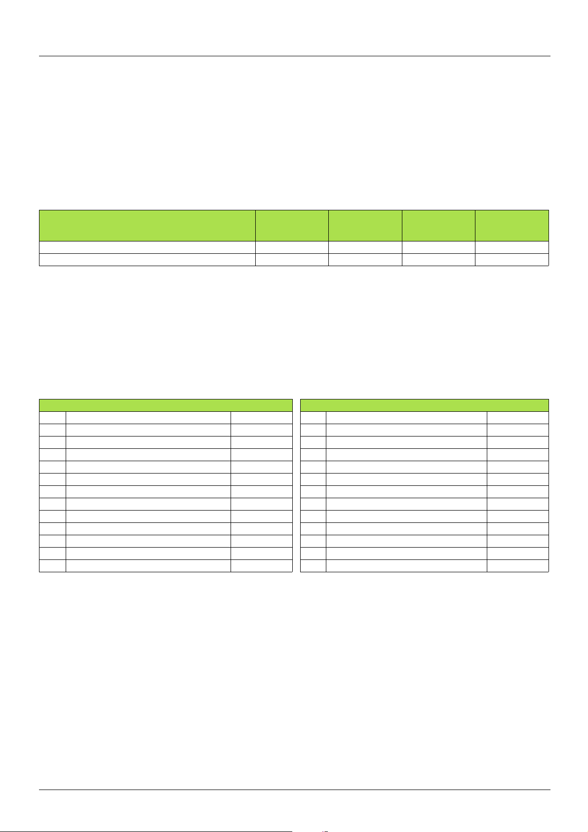
12. IO Scanning service
12. 1. Presentation
The IO Scanning service is used to exchange periodic I/O data between:
• A controller or PLC (IO Scanner).
• Devices (IO Scanning servers).
This exchange is usually performed by implicit services, thus avoiding the need to program the controller (PLC).
The IO Scanner periodically generates the Read/Write Multiple Registers (23 = 16#17) request.
The IO Scanning service operates if it has been enabled in the PLC and the drive.
The drive parameters assigned to IO Scanning have been selected by default. This assignment can be modified by configuration.
The table below indicates the tools which can be used to modify these configurations:
Functions Graphic display
terminal
Enable IO Scanning pppp
Configuring the IO Scanning variables pp
The drive IO Scanning service can also be configured by the Ethernet card Modbus server.
When the IO Scanning service has been enabled in the Altivar 71 drive:
• A TCP connection is assigned to it.
• The parameters assigned in the periodic variables are exchanged cyclically between the Ethernet card and the drive.
• The parameters assigned to the periodic output variables are reserved for IO Scanning. They cannot be written by other Modbus services,
even if the IO Scanner is not sending its periodic output variables.
Integrated
display
terminal
PowerSuite
software
workshop
Standard
Web server
12. 2. Periodic variables
Output variables (written by IO Scanner) Input variables (read by IO Scanner)
No. Meaning/default assignment Configurable No. Meaning/default assignment Configurable
0 Reserved no 0 Reserved no
1 Control word (CMd) yes 1 Status word (EtA) yes
2 Speed setpoint (LFrd) yes 2 Output speed (rFrd) yes
3 Not assigned yes 3 Not assigned yes
4 Not assigned yes 4 Not assigned yes
5 Not assigned yes 5 Not assigned yes
6 Not assigned yes 6 Not assigned yes
7 Not assigned yes 7 Not assigned yes
8 Not assigned yes 8 Not assigned yes
9 Not assigned yes 9 Not assigned yes
10 Not assigned yes 10 Not assigned yes
11-31 Reserved no 11-31 Reserved no
It is possible to configure the assignment of periodic variables 1 to 10.
Note: • Avoid configuring the drive configuration parameters as periodic output variables because they cannot be modified with the
1755879 11/2009 39
motor running (DSP 402 state “5-Operation Enabled”).
• Monitoring parameters must not be configured as periodic output variables, because they cannot be written.
Page 40

12. IO Scanning service
The values of the periodic variables are listed in a table.
This table can be accessed in read-only mode by the Ethernet card Modbus server (Unit ID = 251).
Address Description Default value Address Description Default value
40 001 Value of output variable 1 Value of the
control word
(CMd)
40 002 Value of output variable 2 Value of the speed
setpoint (LFrd)
40 003 Value of output variable 3 40 019 Value of input variable 3
40 004 Value of output variable 4 40 020 Value of input variable 4
40 005 Value of output variable 5 40 021 Value of input variable 5
40 006 Value of output variable 6 40 022 Value of input variable 6
40 007 Value of output variable 7 40 023 Value of input variable 7
40 008 Value of output variable 8 40 024 Value of input variable 8
40 009 Value of output variable 9 40 025 Value of input variable 9
40 010 Value of output variable 10 40 026 Value of input variable 10
12. 3. Address table
40 017 Value of read register 1 Value of the status
word (EtA)
40 018 Value of read register 2 Value of the output
speed (rFrd)
The periodic variables are defined in the address table.
This table can be accessed in read-write mode by the Ethernet card Modbus server (Unit ID = 251).
Address Description Default value Address Description Default value
50 001 Logic address
of output variable 1
50 002 Logic address
of output variable 2
50 003 Logic address
of output variable 3
50 004 Logic address
of output variable 4
50 005 Logic address
of output variable 5
50 006 Logic address
of output variable 6
50 007 Logic address
of output variable 7
50 008 Logic address
of output variable 8
50 009 Logic address
of output variable 9
50 010 Logic address
of output variable 10
To modify the address table, IO Scanning must be disabled (only when the motor is stopped).
Address of the control word
(CMd) = 8501
Address of the speed setpoint
(LFrd) = 8602
0 50 019 Logic address
0 50 020 Logic address
0 50 021 Logic address
0 50 022 Logic address
0 50 023 Logic address
0 50 024 Logic address
0 50 025 Logic address
0 50 026 Logic address
50 017 Logic address
of input variable 1
50 018 Logic address
of input variable 2
of input variable 3
of input variable 4
of input variable 5
of input variable 6
of input variable 7
of input variable 8
of input variable 9
of input variable 10
Address of the status
word (EtA) = 3201
Address of the output
speed (rFrd) = 8604
0
0
0
0
0
0
0
0
40 1755879 11/2009
Page 41

13. FDR service
13. 1. Presentation
The FDR (Faulty Device Replacement) service is used to simplify the maintenance of drives connected on the Ethernet network.
In the event of a drive malfunction, this service automatically reconfigures its replacement.
The new drive (FDR client) retrieves:
• Its IP addresses and the FDR file path from a DHCP server.
• The FDR file from an FTP server, if the drive is not configured in local configuration.
In practice, the DHCP server and the FTP server are the same device (TSX Premium or Quantum PLC).
The FDR file contains:
• The Ethernet parameters (configuration of IO Scanning, FDR etc.).
• The drive parameters (drive, functions, application, etc.).
The FDR service is based on identification of the device by a “Device Name”. In the case of the Altivar 71 drive, this is represented
by the [DEVICE NAME] parameter.
Configuration using the drive graphic display terminal or the integrated display terminal is explained in the “Configuration” section.
Configuration using the standard Web server is explained in the “Standard Web server” section.
For configuration using the PowerSuite software workshop, refer to the software online help.
Note: Check that all the network devices do have different “Device Names”.
The FDR server controls duplication of “Device Names” (it does not assign an IP address that has already been assigned and is active).
If the same IP address is supplied on 2 devices, the 2nd should trigger an IP address duplication (network management fault which leads
to a drive fault [External fault com.] (EPF2) by default).
If the FDR service has been enabled, the Ethernet card attempts to restore its IP addresses on each power-up. Each time the procedure
fails, the Ethernet card reiterates its FDR requests (DHCP).
Where the configuration also needs to be downloaded by the FDR server:
After assigning the Ethernet card IP addresses, if the configuration download fails, the Ethernet card detects a network management fault
(which leads to a drive fault [External fault com.] (EPF2) by default).
1755879 11/2009 41
Page 42

13. FDR service
IP assignment
Save
13. 2. Local configuration
If the drive parameter configuration is local, the FDR server only assigns the IP addresses:
• Card IP address.
• Subnet mask.
• Gateway IP address.
On connection to the network, the drive automatically saves its parameters in the FDR server.
To make the system operational, it is necessary to:
• Configure the FDR server.
• Configure the drive.
• Turn off the drive.
• Connect the drive to the network.
M Configure the FDR server
See the PLC manual or the section on software setup using PL7.
M Configure the drive
In the [1.9 - COMMUNICATION] (COM-) menu, [ETHERNET] (EtH-) submenu:
• Leave the IP address [IP card] (IPC1) (IPC2) (IPC3) (IPC4) at the value [0.0.0.0] (0) (0) (0) (0)
• Enable the FDR service: [FDR validation] (FdrU) = [Yes] (YES)
• Select local drive configuration: [FDR Local Config.] (LCFG) = [Yes] (YES)
Enter the device name, [DEVICE NAME], in the [7. DISPLAY CONFIG.] menu, [7.1 USER PARAMETERS] submenu.
This menu can only be accessed in expert mode: In the [2 ACCESS LEVEL] (LAC-) menu, set the level to [expert] (EPr).
M Turn the drive off and then back on again
Turn the drive off and then back on again (control voltage if a separate power supply is being used), otherwise the device name is not taken
into account.
M Connect the drive to the network
42 1755879 11/2009
Page 43

13. FDR service
IP assignment
Save
Downloading
13. 3. Downloaded configuration
If the drive parameter configuration has been downloaded, the FDR server assigns:
M The IP addresses
• Card IP address.
• Subnet mask.
• Gateway IP address.
• FDR server IP address.
M Drive parameters (configuration)
b First use
Procedure:
• Configure the drive.
• Turn off the drive.
• Connect the drive to the network.
• Configure the FDR server (see the PLC manual).
• Supply the FDR server with the configuration file.
• Check that the system is operational.
In the procedure described below, the configuration file is supplied to the FDR server, via the Ethernet network, using a save command
performed on the drive graphic display terminal.
Note: This procedure can also be performed using a Web browser, which is more user-friendly than the drive graphic display terminal
(see the “Standard Web server” section).
M Configure the drive
In the [1.9 - COMMUNICATION] (COM-) menu, [ETHERNET] (EtH-) submenu:
• Leave the IP address [IP card] (IPC1) (IPC2) (IPC3) (IPC4) at the value [0.0.0.0] (0) (0) (0) (0).
• Enable the FDR service: [FDR validation] (FdrU) = [Yes] (YES).
• Caution, before the first connection, you must select local drive configuration: [FDR Local Config.] (LCFG) = [Yes] (YES).
The drive must first supply the configuration to the server.
WARNING
RISK OF UNINTENDED EQUIPMENT OPERATION
Always select the local configuration option [FDR Local Config.] (LCFG)=[Yes] (YES) when configuring the first drive. If this option is
not selected, an invalid or null configuration file may be uploaded to the FDR server. Subsequent drives would then receive incorrect
configuration files, leading to unexpected behavior.
Failure to follow this instruction can result in death, serious injury, or equipment damage.
Enter the device name, [DEVICE NAME], in the [7. DISPLAY CONFIG.] menu, [7.1 USER PARAMETERS] submenu.
This menu can only be accessed in expert mode: In the [2 ACCESS LEVEL] (LAC-) menu, set the level to [expert] (EPr).
M Turn the drive off and then back on again
Turn the drive off and then back on again (control voltage if a separate power supply is being used), otherwise the device name is not taken
into account.
M Connect the drive to the network
1755879 11/2009 43
Page 44

13. FDR service
M Download the IP addresses
• Connect the drive and the FDR server (PLC) to the Ethernet network.
• The server downloads the IP addresses to the Ethernet card.
Check that the operation has proceeded correctly:
• The “STS” LED should be on.
You can also check, in the [1.9 - COMMUNICATION] (COM-) menu, [ETHERNET] (EtH-) submenu whether the [IP card] (IPC1)
(IPC2) (IPC3) (IPC4), [IP Mask] (IPM1) (IPM2) (IPM3) (IPM4) and [IP Gate] (IPG1) (IPG2) (IPG3) (IPG4)
parameters have values other than [0.0.0.0] (0) (0) (0) (0).
M Save the drive configuration parameters in the FDR server
• Configure the drive parameters.
In the [1.9 - COMMUNICATION] (COM-) menu, [ETHERNET] (EtH-) submenu:
• Specify that the drive configuration is to be downloaded from the FDR server on each power-up: [FDR Local Config.] (LCFG) = [No] (nO).
• Send a save command to the FDR server: [FDR Action]
After execution of the command, the [FDR Action] (FdrA) parameter reverts to the value [IDLE] (IdLE).
M Check that the system is operational
Check that the operation has proceeded correctly:
• The “STS” LED should be on.
• The [FDR state] (FdrE) parameter should be at the value [OPE] (OPE).
(FdrA) = [SAVE] (SAUE).
If the save operation has not been successful, the card detects a communication (network management) fault which, in factory settings
mode, triggers a drive fault [External fault com.] (EPF2).
b Replacing a drive
Procedure:
• Configure the drive.
• Turn off the drive.
• Connect the drive to the network.
• Check that the drive is operational.
M Configure the drive
In the [1.9 - COMMUNICATION] (COM-) menu, [ETHERNET] (EtH-) submenu:
• Leave the IP address [IP card] (IPC1) (IPC2) (IPC3) (IPC4) at the value [0.0.0.0] (0) (0) (0) (0).
• Enable the FDR service: [FDR validation] (FdrU) = [Yes] (YES).
• Specify that the drive configuration is to be downloaded from the FDR server on each power-up:
[FDR Local Config.] (LCFG) = [No] (nO).
These configurations are the default values.
Enter the device name, [DEVICE NAME], in the [7. DISPLAY CONFIG.] menu, [7.1 USER PARAMETERS] submenu.
This menu can only be accessed in expert mode: In the [2 ACCESS LEVEL] (LAC-) menu, set the level to [expert] (EPr).
M Turn the drive off and then back on again
Turn the drive off and then back on again (control voltage if a separate power supply is being used), otherwise the device name is not taken
into account.
M Connect the drive to the network
M Check that the system is operational
Check that the operation has proceeded correctly:
• The “STS” LED should be on.
• The [FDR state] (FdrE) parameter should be at the value [OPE] (OPE).
If downloading has not been possible after a period of 2 min following assignment of the IP addresses, the card detects a communication
(network management) fault which, in factory settings mode, triggers a drive fault [External fault com.] (EPF2).
44 1755879 11/2009
Page 45

13. FDR service
13. 4. Periodic saving
Periodic saving of the drive configuration can be configured on the FDR server in either local configuration or downloaded
configuration mode.
In the [1.9 - COMMUNICATION] (COM-) menu, [ETHERNET] (EtH-) submenu:
•Select: [FDR autosave] (FdrS) = [Yes] (YES).
• Set the [FDR t.autosave] (Fdrt) parameter.
Note: Saving too often risks overburdening the network and adversely affecting its performance (factory setting: 10 min).
13. 5. Other commands
On request, the configuration saved in the FDR server can be downloaded to the drive using the [FDR Action] (FdrA)
command = [REST] (rESt).
The saved configuration can be deleted from the FDR server using the [FDR Action] (FdrA) command = [DEL] (dEL).
13. 6. Configuration file
The configuration file, XXXX.prm where XXXX is the DeviceName, is an HTML file which contains the entire drive configuration
as a comment.
The HTML format is a simple way of providing the user with a summary of the configuration. An example appears below:
FDR Configuration File
File Revision: 2
ATV Revision: 1.0IE1.0
Catalog number: ATV-71HU15M3
CheckSum File: SE92
b Limitations
• The FDR configuration file XXXX.prm coming from an Ethernet V2.1 option board can not be applied on a V1.1 option board.
• The FDR service is able to store the current configuration of the drive, but does not provide the possibility to store muli-configurations or
multi-parameters configurations.
1755879 11/2009 45
Page 46

14. Standard Web server
“Home” menu
“Monitoring” menu
“Diagnostics” menu
“Setup” menu
“Altivar Viewer” page
“Data Viewer” page
“Ethernet Statistics” page
“Security” submenu
“Documentation” menu
www.schneider-electric.com
“FDR Agent” page
“IO Scanner” page
“HTTP password” page
“Data write password” page
“Altivar Chart” page
A
A
A
A
A
A
14. 1. Web server functions
Menu Page Function
HOME English Home page
Altivar Viewer Display of the main drive parameters (motor speed, state of drive logic and analog I/O, status)
MONITORING
DIAGNOSTICS Ethernet Statistics
SETUP
DOCUMENTATION References Link to the site http://www.schneider-electric.com
Data Viewer Display and modification (password-protected) of the drive parameters, arranged by category
Altivar Chart
[Security]
HTTP password
[Security]
Data write password
FDR Agent Display of the state and management of the Ethernet card FDR agent
IO Scanner
Display of two drive parameters (speed, voltage, etc.) in the form of an oscilloscope type
time chart
Display and resetting of the communication statistics
Drive identification
Changing the HTTP password used to access the Web server
Changing the Write password that allows modification of the parameters
Display and modification (password-protected) of the assignment of the IO Scanning
periodic variables
Enabling and disabling of IO Scanning (password-protected)
Setting (password-protected) of the IO Scanning and Modbus TCP messaging time outs
Pages which contain applets are marked “A”.
46 1755879 11/2009
Page 47

14. Standard Web server
14. 2. Applets
The Web server downloads Java programs called “applets” to your computer. These applets communicate with the drive using Modbus
services (on port 502), thus establishing one or more connections between the computer and the drive. Until an applet has been fully
transmitted from the drive to the browser, a gray rectangle appears in the place reserved for it in the page.
The applet connects when the page is opened and remains connected until the page is closed.
Display problems can appear with the SUN “Java virtual machine”. Use the Internet Explorer default JVM.
The applets associated with the Web pages monitor communication with the drive. When the drive no longer responds to requests to update
the data, the message “Link down” is displayed in one field and all the other field contents are emptied.
Subsequently, the description of each page indicates the data refresh period requested by the applet loaded on the computer. The refresh
period actually observed depends on:
• The performance of the computer on which the Web browser is running.
• The communication system response time.
• The amount of data to be refreshed on the page.
1755879 11/2009 47
Page 48

14. Standard Web server
14. 3. Access to the Web server
Number of Modbus TCP connections 0
To connect to the Web server of a drive located, for example, at IP address 139.160.69.241 enter the URL
“http://139.160.69.241/” in the address bar of a Web browser.
When the browser first connects to the drive Web server, it requests entry of a user name and a password (HTTP password).
By default, the user name and the password (HTTP password) are both “USER” (upper case).
If authentication is accepted, the home page is displayed. If not, after three failed attempts, access to this page is denied:
To attempt a new connection to the drive server home page, simply refresh the Web browser display (F5 key or “Refresh” button,
for example).
48 1755879 11/2009
Page 49

14. Standard Web server
1
2
1
3
14. 4. Web server user interface
All the drive Web server pages have the same appearance:
1 A bar at the top containing links to HTML pages for the main menus: “Home”, “Documentation”, “Monitoring”, “Control”, etc.
This bar is the same regardless of which HTML page is being viewed.
Note: The “Control” and “Maintenance” menus are inoperative and grayed-out. They only appear because of the “Transparent Ready”
common interface.
2 A menu down the left-hand side which displays links to the HTML pages available in the selected menu.
3 The center part of the window displays the information for the selected page.
14. 5. “Home” menu
Number of Modbus TCP connections 0
The home page or “Home” menu contain the following items:
• A “Languages” submenu containing:
- A link to the “English” page
The only link in the “Languages” submenu sends the user to the home page in English and configures the Web browser to open the HTML
pages located in the corresponding directory (e.g., the “http://139.160.69.241/html/english/” directory becomes the standard directory in the
case of English).
14. 6. “Monitoring” menu
Number of Modbus TCP connections 0
The “Monitoring” menu contains the following items:
• A link to the “Altivar Viewer” page.
• A link to the “Data Viewer” page.
• A link to the “Altivar Chart” page.
1755879 11/2009 49
Page 50

14. Standard Web server
14. 7. “Altivar Viewer” page
Number of Modbus TCP connections 2 Refresh period 0.5 s
This page gives an overview of the drive state.
The state indicated in the “Altivar State” field corresponds to the display on the drive integrated display terminal. A delay may sometimes
be noticed between the displays on the Web server and the display terminal, depending on the performance of the computer used to display
the pages using a Web browser and the communication system performance.
The motor speed displayed on the “Motor Speed” gauge is calibrated according to the maximum frequency [Max frequency] (tFr)
and the number of pairs of poles [Pr] (PPn).
The LI… area gives the state of the drive terminals (logic inputs LI1 to LI14, logic outputs LO1 to LO4, relay outputs R1 to R4, analog inputs
AI1 to AI4 and analog outputs AO1 to AO3). When a logic input is active, the LED is green. When a logic output is active, the LED is red.
50 1755879 11/2009
Page 51
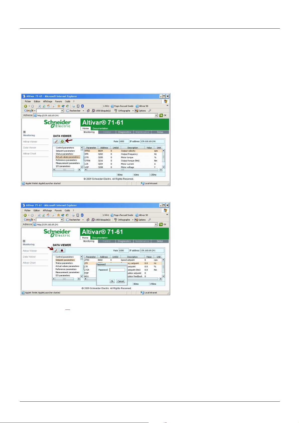
14. Standard Web server
14. 8. “Data Viewer” page
This page is used to display the drive parameters and modify their values.
The parameters are arranged in groups, and consistent with the keypad and user manuals
The display mode for each value depends on the nature of the parameter.
• The unit for the physical values is displayed in the "Unit" column.
• The registers (bit fields) are displayed in hexadecimal format (16#xxxx).
• Signed values are displayed as such.
To begin the monitoring, click the "Start animation" button :
To modify the parameter value, click the "Write value of selected row" button then select the parameter to modify
It is only possible to modify the parameter values after entering the "Write password" (see "HTTP password" and "Data write password
pages" section on page 54
also a "Cancel" button, for canceling the password entry. After entering the password, press the Enter key so that it is taken into account
by the Web browser.
When the value of a parameter cannot be modified, a warning appears : "This parameter can't be written !"
This is the case for all parameters until you have correctly entered the Password.
). Click on the "Password" button to enter this password. An entry field then appears in the parameter table, and
If IO Scanning has been enabled, modifying the value of a parameter assigned to periodic output variables will have no effect since this
value is updated cyclically by the PLC. The same applies if a parameter is written periodically by a Modbus service.
WARNING : It is possible to write the cmonnad word using the DATA VIEWER. It is mandatory to configure an IP Master in order
to avoid any not desired action
1755879 11/2009 51
Page 52

14. Standard Web server
14. 9. “Altivar Chart” page
Number of Modbus TCP connections 1 Refresh period 1 s
This page is used to see how two drive parameters evolve over time.
Two parameters can be selected and displayed simultaneously. To do this, select them in the Trace1 and Trace2 list.
To define the display range better, you can modify the curve min and max points by entering the values directly in the fields: Min and Max
of each trace.
In order to speed up sampling, it is possible to put the value 0 in the Intv(s) entry field.
Note: Entering the value 0 increases the traffic on the Ethernet network and can cause collision problems if there is too much traffic, thereby
reducing the overall network performance. The sampling period can be increased.
To start the oscilloscope function, press the Run/Stop button. Pressing the button again halts sampling and updates the screen.
Reset: clears the active traces.
14. 10. “Diagnostics” menu
Number of Modbus TCP connections 0
The “Diagnostics” menu contains the following item:
• A link to the “Ethernet Statistics” page.
52 1755879 11/2009
Page 53

14. Standard Web server
14. 11. “Ethernet Statistics” page
Number of Modbus TCP connections 1 Refresh period 0.5 s
This page provides the Ethernet statistics and the drive identification data.
14. 12. “Setup” menu
Number of Modbus TCP connections 0
The “Setup” menu contains the following items:
• A “Security” submenu containing:
- A link to the ”HTTP password” page.
- A link to the ”Data write password” page.
• A link to the ”FDR Agent” page.
• A link to the ”IO Scanner” page.
• A link to the ”Email” page.
1755879 11/2009 53
Page 54

14. Standard Web server
14. 13. “HTTP password” and “Data write password pages”
Number of Modbus TCP connections (for each page) 0
These two pages are used to modify the two Web server passwords.
By default, the user name and both passwords are: “USER” (upper case).
The user name can only be modified using the PowerSuite software workshop.
The user name and the “HTTP password” are used to access the Web server in display mode.
The “Write password” is used to access the Web server in modification mode.
When the value of a parameter cannot be modified, the background of the corresponding cell appears grayed-out. This is the case for all
parameters until you have correctly entered the “Write password”.
Note: Do not lose the user name or the passwords. If they are lost, the Web server can no longer be used, and the card has to be sent
for repair.
54 1755879 11/2009
Page 55

14. Standard Web server
14. 14. “FDR Agent” page
Number of Modbus TCP connections 1 Refresh period 1s
This page displays the main parameters used by the VW3 A3 310 Ethernet card FDR function and is used to configure these parameters.
See the “FDR Service” section.
Information
on the FDR
Agent page
IP Address [IP card]
NetMask [IP Mask]
Gateway [IP Gate]
FTP Server [IP FDR]
DeviceName [DEVICE NAME] Used by the DHCP server to assign the Ethernet card IP addresses dynamically
Device File Not accessible Name of FDR configuration file.
Device Reference - Drive catalog number.
Checksum File Not accessible Drive configuration Checksum value. Whenever a drive parameter is modified, this value
Corresponding
terminal display
(IPC-)
(IPM-)
(IPG-)
(IPF-)
Description/Possible values
Ethernet card IP address
Subnet mask
Gateway IP address
Indicates the IP address of the FDR server that has supplied the Ethernet card
configuration, in particular its IP addresses.
This is the server which also supplies the drive configuration file, if [FDR Local Config.]
(LCFG) = [No] (nO).
(example: Machine 157).
The file name is consistent with the DeviceName (in our example: Machine 157.prm).
If the FDR server file has not been downloaded to the drive, “Local” is displayed in this field.
changes.
1755879 11/2009 55
Page 56

14. Standard Web server
Information
on the FDR
Agent page
Validation [FDR validation]
Local Config [FDR Local Config.]
File Error [FDR Error Mgt.]
AutoSave [FDR autosave]
Period [FDR t.autosave]
FDR State [FDR state]
Error Code [FDR fault]
Save Counter Not accessible Number of times the configuration has been saved to the FDR server.
Restore Counter Not accessible Number of times the configuration has been downloaded from the FDR server.
Delete Counter Not accessible Number of times the configuration file has been deleted in the FDR server.
Save File [FDR Action]
Restore File [FDR Action]
Delete File [FDR Action]
Reset counter Not accessible Command to reset the “Save counter”, “Restore counter” and “Delete counter” counters.
Corresponding
terminal display
(FdrU)
(LCFG)
(FdrF)
(FdrS)
(Fdrt)
(FdrE)
(Fdrd)
(FdrA)
(FdrA)
(FdrA)
Description/Possible values
Enables the FDR function
• Off = [No] (nO): FDR service disabled.
•On = [Yes] (YES): FDR service enabled.
Selection of local or server configuration
• Off = [No] (nO): The drive configuration is downloaded from an FDR server.
•On = [Yes] (YES): The drive configuration is local.
Enables the FDR fault management process.
• Off = [No] (nO): In the event of a problem with the FDR file (missing or invalid),
the Ethernet card does not trigger an Ethernet (network management) fault.
•On = [Yes] (YES): In the event of a problem with the FDR file (missing or invalid),
the Ethernet card triggers a network management fault.
Enables periodic saving of the FDR service.
• Off = [No] (nO): Automatic saving disabled.
•On = [Yes] (YES): Automatic saving enabled.
Interval for periodic saving of the FDR service.
2 min to 9999 min
FDR service state.
• Idle = [IDLE] (IdLE): FDR service inactive.
• Initialization = [INIT] (InIt): Initialization of the current Ethernet card.
• Configuration = [CONF] (COnF): Configuration of the current Ethernet card.
• Ready = [RDY] (rdY): Ethernet card ready.
• Get Conf = [GET] (GEt): Downloads the current configuration from the FDR server.
• Store Conf = [SET] (SEt): Saves the current configuration to the FDR server.
• Apply Conf = [APP] (APP): Writes the FDR server configuration to the drive.
• Operational = [OPE] (OPE): Operational.
• Unconfigured = [UCFG] (UCFG): FDR service fault.
Ethernet error code.
• No error = [0]: No fault.
• Service Unavailable = The FDR server is not available.
•= [2]: The FDR configuration file is not compatible with the drive type
(example: the drive is not the same rating as that defined in the FDR file).
•= [3]: Error reading the FDR configuration file on the server.
•= [4]: Error writing the FDR configuration file to the server.
•= [7]: Time out for receipt of the FDR configuration file from the server.
•= [9]: Duplication of IP address.
• File Not Found = [12]: The FDR configuration file is missing.
This counter is incremented even if the drive configuration is identical to that of the server.
This counter is not incremented if the drive configuration is identical to that of the server
(comparison of checksums).
Command to save the configuration to the FDR server.
Corresponds to the display terminal command: [SAVE] (SAUE).
Command to download the configuration from the FDR server.
Corresponds to the display terminal command: [REST] (rESt).
Command to delete the configuration file in the FDR server.
Corresponds to the display terminal command: [DEL] (dEL).
56 1755879 11/2009
Page 57

14. Standard Web server
14. 15. “IO Scanner” page
Number of Modbus TCP connections 1 Refresh period 1s
This page is used to:
• Enable or disable IO Scanning.
• Display and modify assignment of the IO Scanning periodic variables.
• Set the communication monitoring time out.
The default configuration is described in the screen below:
All modifications are protected by the “Write password” modification password. Click on the “PassWord” button to enter the
“Write password”. After correctly entering the password, you can access “IoScanner”, “Time Out (s)”, “Master”, “Output parameters”,
“Input parameters” and the “Save” and “Abort” buttons.
By default, the password is “USER”. It can be modified in the “Data write password” page.
1755879 11/2009 57
Page 58

14. Standard Web server
b Enabling IO Scanning
Control by the IO Scanner is enabled if the “IoScanner” field is at the value “Yes” and disabled by the value “No”.
The “IoScanner” field corresponds to the parameter [IO Scan.activ.] (IOSA).
WARNING
RISK OF UNINTENDED EQUIPMENT OPERATION
• Do not disable a drive's IO scanning support when the PLC is using the IO scanner to monitor/control client devices.
• Do not modify the assignment of the periodic variables if the PLC is using IO scanning to monitor/control client devices.
Disabling a drive's IO Scanning or modifying the assignment of periodic variables can result in a loss of control via the network, and could
result in unintended equipment operation.
Failure to follow this instruction can result in death, serious injury, or equipment damage.
Note: Disabling IO Scanning results in loss of control if a PLC is using an IO Scanner.
Before disabling IO Scanning, you must disable the time out (set the value to 0). However, communication monitoring remains active and
the card triggers a communication fault at the end of the period defined by the time out. In factory settings mode, the drive then changes to
[Com. network] (CnF) fault mode.
Once the value in the “IoScanner” field has been modified, it may take a while to update the page, depending on the capacity of your
computer.
The “IoScanner” field corresponds to the parameter [IO Scan.activ.] (IOSA).
b Assigning the IO Scanning periodic variables
Note: Modifying the assignment of the periodic variables can result in loss of control if a PLC is using an IO Scanner.
To modify the IO Scanning periodic variables, proceed as follows:
1 Enter “No” in the “Io Scanner” field. 2 Modify the assignment of periodic variables. 3 Apply these modifications using the “Save” button. 4 Enter “Yes” in the “Io Scanner” field.
Once the value in the “IoScanner” field has been set to “No”, it may take a while to update the page, depending on the capacity of your
computer.
A dropdown menu is used to modify the assignment of each of the periodic variables.
Click on the periodic variable whose assignment you wish to modify, then choose the code corresponding to the drive parameter to be
assigned.
All modifications to “Output parameters” and/or “Input parameters” can be confirmed by clicking the “Save” button or canceled by clicking
the “Abort” button.
Each time the “Save” button is pressed the address table will be saved to an EEPROM on the Ethernet card.
The assignments are now saved, even if the power is turned off.
58 1755879 11/2009
Page 59

14. Standard Web server
b Time out
This page can also be used to modify the communication monitoring “time out”. All entries must be confirmed by pressing “Enter”.
The accepted values are as follows:
0: No communication check.
0.5 to 60.0 s: Time out value.
See the “Configuration - Communication faults” section.
The default time out value is 2 s (display: “2.0”).
The “Time Out” field corresponds to the [time out] (tOUt) parameter.
b Master
See the “Reserving control” section.
To configure reservation, enter an IP address other than [0.0.0.0] in the “Master” field. This field is equivalent to the [IP Master] (IPP-)
parameter.
1755879 11/2009 59
Page 60

14. Standard Web server
14. 16. "Email" page
The configuration page of the Email service is available in the setup menu V Email of the option board web page, only for V2.1 version
and above.
This service is able to generate and send emails to a predefined address in case of alarm warning or drive fault. The controller inside option
board can also initiate the sending of an email.
It is possible to configure the Email service after entering the "Write password" (see "HTTP password" and "Data write password pages"
section on page 54
Enter the following information to configure the Email service :
Email IP Server : IP address of the Email server that will process the message (SMTP server)
Email Dest @ : Email address of the Email recipient
Email From @ : Email address of the Ethernet option board which will send the email (this is a virtual address since the option board does
not provide any incoming email box)
Configure the triggering mode for sending Email :
Drive Fault : an Email is sent on a drive fault (triggered by ETA.3)
Drive alarm : an Email is sent on a drive warning (triggered by ETA.7)
Eth. Board fault : an Email is sent on an ethernet board fault
PLC Board status : an Email is sent on demand from the application of the controller inside board
Email example sent on CNF fault of the Ethernet board :
From: ALTIVAR@pascal.fr
Subject: Error CNF on Altivar Drive
Date: Wed, 14 Dec 2005 14:55:32 +0100
Fault occured on Ethernet Board's Drive:
DeviceName: ATV
IP Address: 139.160.69.241
Reference : ATV71H037M3
Description: TimeOut TCP/Modbus (CNF)
).
IMPORTANT NOTICE
This Email has been automatically generated. Please do not reply.
Copyright © 2005, Schneider Automation. All rights reserved
Service diagnostic :
• Email Status
-0 V Idle
-1 V Operational
-2 V Stopped
• SentCount : number of emails successfully sent
• ErrorCount : number of errors occurred
• LastError : last error code (compliant with S
60 1755879 11/2009
Page 61

14. Standard Web server
14. 17. “Documentation” menu
Number of Modbus TCP connections 0
The “Documentation” menu contains a link to the “References” page.
This page displays a link to the site: http://www.schneider-electric.com/.
1755879 11/2009 61
Page 62

15. FTP server
username
HTTP password
IP address
ftp://USER:USER@xxx.xxx.xxx.xx
b Access
The Ethernet card has a structured FTP server which is used to:
• Access the embedded Web server resource files.
• Store the FDR (Faulty Device Replacement) service configuration files.
Access to the FTP server is protected. To access it, the user has to enter a user name and a password:
• The user name is USER.
• The default HTTP password is USER. It can be changed by the standard Web server.
Address format in lnternet Explorer: .
With some FTP clients, it is necessary to click “CANCEL” after connecting.
To obtain this display in Internet Explorer, first activate the “Enable folder view for FTP sites” option (in: Tools, Internet Options …,
Advanced, Browsing).
The FTP server accepts up to 2 FTP clients connected at the same time.
The FTP server content cannot be modified if the motor is running.
62 1755879 11/2009
Page 63

15. FTP server
b Functions
The table below describes the functions available:
FTP functionality Comment
User name check. Accepts or rejects connection Handled
HTTP password check. Accepts or rejects Handled
User output Handled
Type of file system Handled. “DOS”.
Create a volume or disk Not handled
Change file name Handled
Delete a file Handled
Open a file Handled in read/write mode
Read a file Handled
Write a file Handled
Close a file Handled
Open a directory Handled
Close a directory Handled
Change directory Handled
Current directory = parent directory Handled
Delete a directory Handled
Create a directory Handled
Restore current directory Handled
Read next directory input Handled
b File system
The FTP server “fdr” directory is fixed. The RD (remove directory) command therefore has no effect on this directory.
Conversely, the whole “html” directory can be modified using the MD (make directory) and RD commands.
Note: Before modifying the content of this directory, remember to save it to the hard disk of your PC. Do not modify this saved directory
because in the event of a problem, you can use it to restore the original content of the FTP server “html” directory.
The file system is DOS type. The response to DIR or LS commands, handled by the tfFSOpenDir and tfFSGetNextDirEntry functions
is as follows:
08-28-01 08:07AM <DIR> Java
08-28-01 08:07AM 57346 AtvSys.jar
This syntax must be strictly adhered to.
The Ethernet card manages the time and date of Web server file save operations.
But there is a specific procedure for starting the Ethernet card date/time function:
• Connect a browser to the standard Web server.
• Open one of the pages containing a Java applet (Altivar Viewer, Data Viewer, Altivar chart, Ethernet Statistics, FDR agent, IO Scanner).
• On each connection, the applet sends the date and time present on the PC on which it is executed.
The date/time function remains active until the end of the day. After midnight, it is automatically deactivated.
Note: If the date/time function has not been activated, the date and time used to date-stamp the Web server files are those supplied by the
Ethernet card software.
1755879 11/2009 63
Page 64
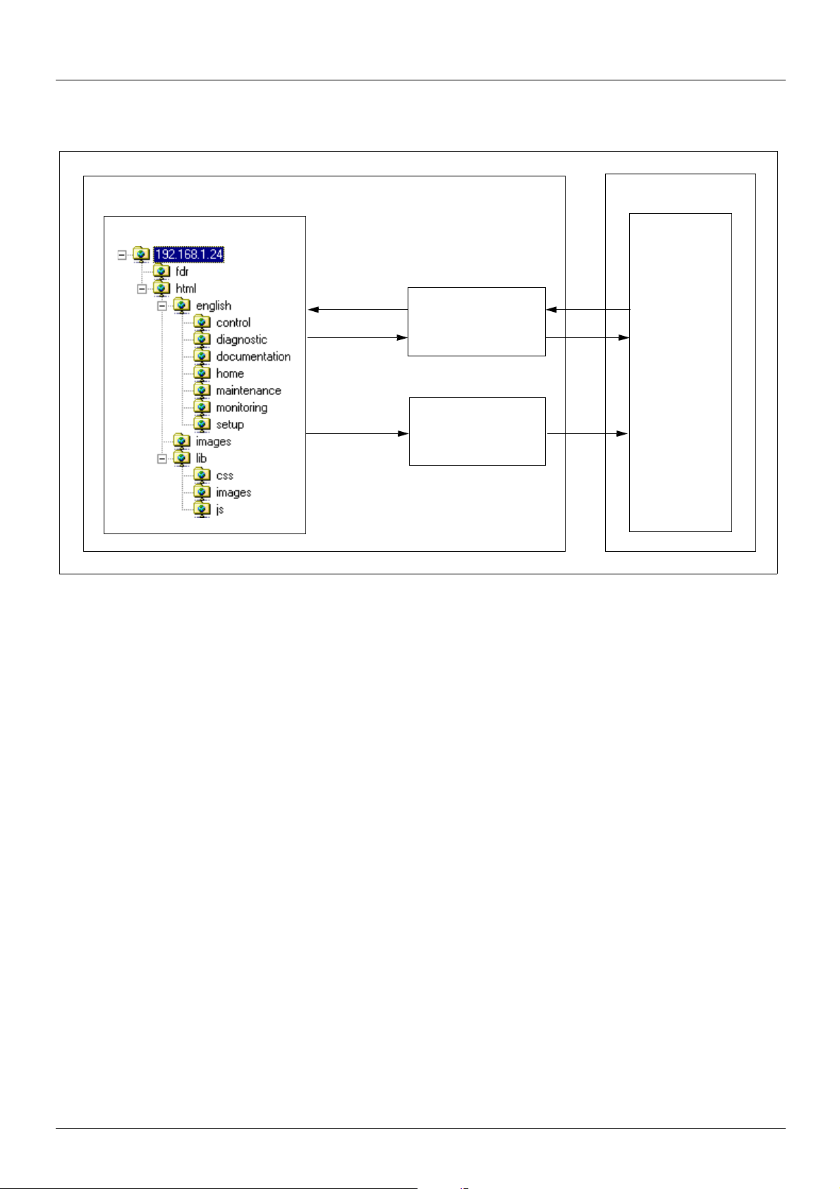
16. Downloading from the Web server
VW3 A3 310 Ethernet card
FTP server
File system
Write to
Flash memory
Read
Read
HTTP server
Internet
Explorer
PC
b Principle
The Ethernet card has an embedded FTP server which authorizes access to the various URLs available for the HTTP server. A browser
such as Internet Explorer can be used to display the URLs like a disk in the Windows explorer. This “disk” consists of various directories
containing the URL files. It is therefore possible to use the different commands managed by the explorer such as deletion, renaming or
writing (downloading) files (check that card IO Scanning has been disabled).
b File management
The memory zone assigned to the Web server URLs consists of 24 blocks:
• 23 sectors of 64 Kb for file storage.
• 1 sector of 64 Kb for the file table.
The Web server storage capacity is 1.5 Mb, i.e. 1536 Kb.
The file table is used to make the link between the HTTP server, the FTP server and the various “URL” files. This table is dynamic, in other
words it changes according to the file write and file delete type user commands. The table is cleared and reprogrammed each time there is
a change.
The maximum number of URL files is limited to 150.
The information relating to each file is as follows:
•File name (32 characters max.).
• Location address in the card memory.
• File size in bytes.
• “FTP” storage directory (html, html/lib/js etc.).
• URL processing function. (Access management, etc.). All the URLs have a default function which requires a password
(“HTTP password”) in order to access them via HTTP, apart from a few exceptions (see below).
64 1755879 11/2009
Page 65

16. Downloading from the Web server
Each URL in the HTTP server is stored in the file table. As a result, the user can easily change the standard Web server by adding, deleting
or modifying the URL files.
However, some URLs are compulsory and/or cannot be modified.
• The “index.htm”, “html/english/home/index.htm” and “html/english/home/home.htm” pages, which form the entry page to the Web server,
are compulsory.
• The WebServer.htm page (see later), and the various HTML requests, such as password modification, are fixed and are not visible via
the FTP server.
The maximum file size is limited to 64 Kb. The size of the AtvSys.jar java archive file, containing all the java applets, is almost 64 Kb.
If additional java applets are required, two archive files must be created.
b Web server
The Web server has a masked page, which cannot be accessed directly via a hyperlink, providing access to a summary of the memory
resources, sector by sector, used by the Web server.
Example of access: http://192.168.1.23/WebServer.htm
Memory Sector Free (bytes) Max (bytes) FastFree (bytes) # File
Sector 12 1,429 65,536 1,429 44
Sector 13 237 65,536 237 01
Sector 14 18,516 65,536 18,516 02
Sector 15 65,536 65,536 65,536 00
Sector 16 65,536 65,536 65,536 00
Sector 17 65,536 65,536 65,536 00
Sector 18 65,536 65,536 65,536 00
Sector 19 65,536 65,536 65,536 00
Sector 20 65,536 65,536 65,536 00
Sector 21 65,536 65,536 65,536 00
Sector 22 65,536 65,536 65,536 00
Sector 23 65,536 65,536 65,536 00
Sector 24 65,536 65,536 65,536 00
Sector 25 65,536 65,536 65,536 00
Sector 26 65,536 65,536 65,536 00
Sector 27 65,536 65,536 65,536 00
Sector 28 65,536 65,536 65,536 00
Sector 29 65,536 65,536 65,536 00
Sector 30 65,536 65,536 65,536 00
Sector 31 65,536 65,536 65,536 00
Sector 32 65,536 65,536 65,536 00
Sector 33 65,536 65,536 65,536 00
Sector 34 65,536 65,536 65,536 00
TOTAL 1,330,902 1,507,328 1,330,902 47
1755879 11/2009 65
Page 66

16. Downloading from the Web server
b Standard Web server resources
The Web server is version HTTP 1.1 and also supports HTTP 1.0.
The HTTP server provides access to the resources (URLs) in the Ethernet card:
• HTML pages
• Images
• Java applets
• Text file (Description of the drive parameters)
Type
HTML pages
File name
(Complete URL)
AtvChart.htm 651
AtvConf.htm 630 Access not permitted -
AtvFdr.htm 628 Pwd change OK -
AtvView.htm 880 Pwd change NOK -
DataEditor.htm 633 Parameter file fdr/Current.prm Variable
DocReferences.htm 660
index.htm 591 images/Telemecanique.gif 3,582
SecurityData.htm 1,570
SecurityHttp.htm 1,523 lib/images/left.gif 870
Statistic.htm 648 lib/images/moins.gif 866
html/english/header.htm 968 lib/images/plus.gif 883
html/english/index.htm 560 lib/images/right.gif 882
html/english/control/index.htm 575
html/english/control/menu.htm 760 AtvSys.jar 64,736
html/english/diagnostic/index.htm 575 Text file DataFile.txt 42,196
html/english/diagnostic/menu.htm 856
html/english/documentation/
index.htm
html/english/documentation/
menu.htm
html/english/home/home.htm 698 lib/js/index.js 895
html/english/home/index.htm 575 lib/js/menu.js 4,824
html/english/home/menu.htm 830 lib/js/tools.js 261
html/english/maintenance/
index.htm
html/english/maintenance/
menu.htm
html/english/monitoring/
index.htm
html/english/monitoring/
menu.htm
html/english/setup/index.htm 575
html/english/setup/menu.htm 1,056
Size
(bytes)
575 lib/js/header.js 5,629
839 lib/js/home.js 536
575
64 lib/css/header.css 988
575 lib/css/main.css 341
960 lib/css/menu.css 655
Type
Special
HMTL
pages
Images
Java
applets
JavaScript
scripts
Cascaded
Style
Sheets
File name
(Complete URL)
WebServer.htm -
altivar71.jpg 14,982
images/
TelemecaniquePocketPC.gif
AtvChart.jar 15,479
html/config.js 418
main.css 314
Size
(bytes)
3,216
The total size is 176,426 bytes for a total of 47 files (excluding special HTML pages and parameters file).
The standard Web server HTML pages have been designed for a 1024 × 768 minimum screen resolution.
66 1755879 11/2009
Page 67

17. SNMP agent
b Presentation
The SNMP protocol (Simple Network Management Protocol) is used to provide the data and services required for managing a network.
The data is stored in an MIB (Management Information Base).
The SNMP protocol is used to read or write MIB data.
Implementation of the Ethernet card SNMP services is minimal, as only the compulsory objects are handled.
Note: An SNMP agent can be configured to generate TRAPS to the SNMP Manager.
TRAPS are used to signal a specific agent state (fault, reset, etc.).
The VW3 A3 310 Ethernet card does not handle TRAPS.
b Tree structure
1755879 11/2009 67
Page 68

17. SNMP agent
b Objects handled
Objects Description Access Default value
SysDescr Text description of the device R SCHNEIDER ATV Altivar Fast
SysObjectID Pointer to the product reference
in the private MIB
SysUpTime Time elapsed since the
Ethernet card was last turned on
SysContact Data item used to contact
the manager of this node
SysName Node administrative name R/W ATV
SysLocation Physical location of the product R/W -
SysService Indicates the type of service
offered by this product
The SysContact, SysName and SysLocation objects can be modified by the user. The values written are saved to the Ethernet card via an
SNMP client not supplied with the VW3 A3 310 Ethernet card.
The size of these character strings is limited to 50 characters.
Using the “public” character string as a “community string” allows the user to access objects in read mode (all objects), whereas the
“schneider” character string enables read access (all objects) and write access (R/W objects only) to the string.
R entreprises.3833.1.7.255.6
R-
R/W -
R72
Ethernet TCP/IP Module
68 1755879 11/2009
Page 69

18. Setup using PL7
b Defining the hardware configuration
Configure an Ethernet module, then configure the module so that it can communicate with the drive. The example shows a TSX Premium
PLC equipped with a TSX ETY5102 module.
1755879 11/2009 69
Page 70

18. Setup using PL7
b BOOTP configuration
The BOOTP server function consists of allocating BOOTP clients their IP addresses.
The activation conditions for the drive BOOTP client are described in the “Configuration - IP Addresses” section.
This window is used to configure the BOOTP server.
The drive MAC address is given on a label attached to its VW3 A3 310 Ethernet card. The IP address assigned to the drive must be entered
in the table against the MAC address.
In this example, the Ethernet card MAC address is 00.80.F4.80.19.76, and its IP address is 139.160.69.242.
Each line in the “Table of supplied addresses” can accept both the MAC and IP addresses of a BOOTP client.
70 1755879 11/2009
Page 71

18. Setup using PL7
b Configuring Modbus messaging
To use Modbus messaging in PL7, the “IP address”, “Subnet mask” and “Gateway address” parameters must be configured in the
“Messaging” tab in the PLC Ethernet module configuration screen.
Data entered in the “Connection configuration” box is used to manage the PLC Modbus messaging service, but has no effect on IO
Scanning which is an independent service.
Example:
PLC IP address 139.160.69.245
Subnet mask 255.255.254.0
Gateway address 139.160.68.1
Drive IP address 139.160.69.242
Xway address IP address Protocol Access Mode
1 1.101 139.160.69.242 MODBUS MULTI
1755879 11/2009 71
Page 72

18. Setup using PL7
b Configuring periodic variables
This window is used to configure the IO Scanning function, described in the IO Scanning Service section on page 39.
In this example:
• The periodic variables of the drive at IP address 139.160.69.242 are associated with PLC data words.
• The drive periodic output variables (control) are associated with the 32 words (WR count) starting at PLC address %MW550 (Write Ref.).
• The drive periodic input variables (monitoring) are associated with the 32 words (RD count) starting at PLC address %MW500 (Read Ref.).
72 1755879 11/2009
Page 73

18. Setup using PL7
The addresses for the PLC %MW words correspond to the configuration in the previous example.
PLC
address
%MW 550 Reserved no %MW 500 Reserved no
%MW 551 Control word (CMd) yes %MW 501 Status word (EtA) yes
%MW 552 Speed setpoint (LFrd) yes %MW 502 Output speed (rFrd) yes
%MW 553 Not assigned yes %MW 503 Not assigned yes
%MW 554 Not assigned yes %MW 504 Not assigned yes
%MW 555 Not assigned yes %MW 505 Not assigned yes
%MW 556 Not assigned yes %MW 506 Not assigned yes
%MW 557 Not assigned yes %MW 507 Not assigned yes
%MW 558 Not assigned yes %MW 508 Not assigned yes
%MW 559 Not assigned yes %MW 509 Not assigned yes
%MW 560 Not assigned yes %MW 510 Not assigned yes
%MW 561
to
%MW 581
Periodic output variable
(default assignment)
Reserved no
Configurable
PLC
address
%MW 511
to
%MW 531
Periodic input variable
(default assignment)
Reserved no
Configurable
1755879 11/2009 73
Page 74

18. Setup using PL7
b Configuring the DHCP address server (FDR)
The DHCP server function consists of allocating BOOTP clients an IP address.
The activation conditions for the drive DHCP (FDR) client are described in the “Configuration - IP Addresses” section.
This window is used to configure the DHCP server.
The user must enter the following fields:
• “Name” to indicate the device name. In our example the ATV name is “ATV_0004”. This “name” corresponds to the FDR function
DeviceName and the drive parameter [DEVICE NAME].
• “IP address” to indicate the device IP address. In our example the ATV IP address is “139.160.69.242”.
• “Netmask” to indicate the subnet mask. In our example the subnet mask is “255.255.254.0”.
• “Gateway” to indicate the gateway IP address. In our example the gateway IP address is “139.160.68.1”.
Each line in the “Table of supplied addresses” can accept both the names and IP addresses of a DHCP client.
74 1755879 11/2009
Page 75

19. Setup using Concept
b Hardware configuration
b Ethernet and I/O Scanner configuration
The screen illustrated below does not apply to the 140-NOE-771-10 master module.
1755879 11/2009 75
Page 76
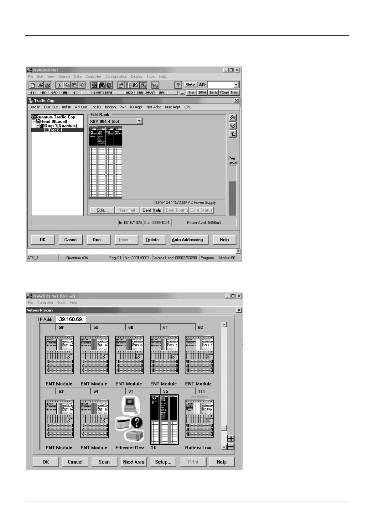
20. Setup using ProWORX NxT
b Hardware configuration (Traffic Cop)
b Network configuration
76 1755879 11/2009
Page 77

20. Setup using ProWORX NxT
b TCP/IP configuration
b I/O Scanner configuration
1755879 11/2009 77
Page 78

ATV61/71_Ethernet_EN_1755879_03
1755879 11/2009
 Loading...