


1672604 01/2009
Altivar 32
Variable Speed Drives
for Synchronous and Asynchronous Motors
®
PROFINET
VW3A3627
10/2013
Communication Manual
HRB25668
www.schneider-electric.com

The information provided in this documentation contains general descriptions and/or technical characteristics
of the performance of the products contained herein. This documentation is not intended as a substitute for
and is not to be used for determining suitability or reliability of these products for specific user applications. It
is the duty of any such user or integrator to perform the appropriate and complete risk analysis, evaluation and
testing of the products with respect to the relevant specific application or use thereof. Neither Schneider
Electric nor any of its affiliates or subsidiaries shall be responsible or liable for misuse of the information
contained herein. If you have any suggestions for improvements or amendments or have found errors in this
publication, please notify us.
No part of this document may be reproduced in any form or by any means, electronic or mechanical, including
photocopying, without express written permission of Schneider Electric. All pertinent state, regional, and local
safety regulations must be observed when installing and using this product. For reasons of safety and to help
ensure compliance with documented system data, only the manufacturer should perform repairs to
components.
When devices are used for applications with technical safety requirements, the relevant instructions must be
followed.
Failure to use Schneider Electric software or approved software with our hardware products may result in
injury, harm, or improper operating results.
Failure to observe this information can result in injury or equipment damage.
© 2013 Schneider Electric. All rights reserved.
2 HRB25668 10/2013

Table of Contents
Table of Contents
Safety Information . . . . . . . . . . . . . . . . . . . . . . . . . . . . . . . . . . . . . . . . . . . . . . . . . . . . 5
About the Book. . . . . . . . . . . . . . . . . . . . . . . . . . . . . . . . . . . . . . . . . . . . . . . . . . . . . . . 6
Chapter 1 Altivar PROFINET Overview . . . . . . . . . . . . . . . . . . . . . . . . . . . . . . . . . . . . . . . . . . . . . 9
Overview. . . . . . . . . . . . . . . . . . . . . . . . . . . . . . . . . . . . . . . . . . . . . . . . . . . . . . . . . . . . 10
PROFINET Fieldbus Module Features Overview. . . . . . . . . . . . . . . . . . . . . . . . . . . . . 10
PROFINET . . . . . . . . . . . . . . . . . . . . . . . . . . . . . . . . . . . . . . . . . . . . . . . . . . . . . . . . . . 11
Modbus TCP. . . . . . . . . . . . . . . . . . . . . . . . . . . . . . . . . . . . . . . . . . . . . . . . . . . . . . . . . 11
PROFINET and Ethernet Features. . . . . . . . . . . . . . . . . . . . . . . . . . . . . . . . . . . . . . . . 11
Web server . . . . . . . . . . . . . . . . . . . . . . . . . . . . . . . . . . . . . . . . . . . . . . . . . . . . . . . . . . 11
Notation rules in this manual . . . . . . . . . . . . . . . . . . . . . . . . . . . . . . . . . . . . . . . . . . . . 11
Chapter 2 Hardware Setup . . . . . . . . . . . . . . . . . . . . . . . . . . . . . . . . . . . . . . . . . . . . . . . . . . . . . . 13
Hardware Presentation. . . . . . . . . . . . . . . . . . . . . . . . . . . . . . . . . . . . . . . . . . . . . . . . . 14
Firmware and GSDML Version Compatibility . . . . . . . . . . . . . . . . . . . . . . . . . . . . . . . . 14
Installation . . . . . . . . . . . . . . . . . . . . . . . . . . . . . . . . . . . . . . . . . . . . . . . . . . . . . . . . . . 14
Wiring . . . . . . . . . . . . . . . . . . . . . . . . . . . . . . . . . . . . . . . . . . . . . . . . . . . . . . . . . . . . . . 17
Installation Topology. . . . . . . . . . . . . . . . . . . . . . . . . . . . . . . . . . . . . . . . . . . . . . . . . . . 18
Chapter 3 Configuration and Parameters . . . . . . . . . . . . . . . . . . . . . . . . . . . . . . . . . . . . . . . . . . 19
Network Settings . . . . . . . . . . . . . . . . . . . . . . . . . . . . . . . . . . . . . . . . . . . . . . . . . . . . . 20
iPar Settings . . . . . . . . . . . . . . . . . . . . . . . . . . . . . . . . . . . . . . . . . . . . . . . . . . . . . . . . . 22
Modbus TCP Settings. . . . . . . . . . . . . . . . . . . . . . . . . . . . . . . . . . . . . . . . . . . . . . . . . . 23
Chapter 4 Configuration . . . . . . . . . . . . . . . . . . . . . . . . . . . . . . . . . . . . . . . . . . . . . . . . . . . . . . . . 25
Configuring the Control Channel . . . . . . . . . . . . . . . . . . . . . . . . . . . . . . . . . . . . . . . . . 26
Configuring Monitor Parameters. . . . . . . . . . . . . . . . . . . . . . . . . . . . . . . . . . . . . . . . . . 29
Configuring Communication Interruption Management . . . . . . . . . . . . . . . . . . . . . . . . 30
Chapter 5 Diagnostics and monitoring . . . . . . . . . . . . . . . . . . . . . . . . . . . . . . . . . . . . . . . . . . . . 31
LED Indicators . . . . . . . . . . . . . . . . . . . . . . . . . . . . . . . . . . . . . . . . . . . . . . . . . . . . . . . 32
Communication Diagnostics . . . . . . . . . . . . . . . . . . . . . . . . . . . . . . . . . . . . . . . . . . . . . 34
Monitoring of Communication Channels. . . . . . . . . . . . . . . . . . . . . . . . . . . . . . . . . . . . 36
Control-Signal Diagnostics . . . . . . . . . . . . . . . . . . . . . . . . . . . . . . . . . . . . . . . . . . . . . . 38
Chapter 6 Telegram 100, 101, 102. . . . . . . . . . . . . . . . . . . . . . . . . . . . . . . . . . . . . . . . . . . . . . . . .41
Overview. . . . . . . . . . . . . . . . . . . . . . . . . . . . . . . . . . . . . . . . . . . . . . . . . . . . . . . . . . . . 42
Configuring an ATV32 With a Siemens© S7-300. . . . . . . . . . . . . . . . . . . . . . . . . . . . . 46
Configuration of the Altivar 32 With the Telegram 100. . . . . . . . . . . . . . . . . . . . . . . . . 47
Configuring an ATV32 With the Telegram 101 or 102 . . . . . . . . . . . . . . . . . . . . . . . . . 48
Parameters Management With the telegram 100, 101, 102. . . . . . . . . . . . . . . . . . . . . 49
Chapter 7 Telegram 1. . . . . . . . . . . . . . . . . . . . . . . . . . . . . . . . . . . . . . . . . . . . . . . . . . . . . . . . . . . 51
Overview. . . . . . . . . . . . . . . . . . . . . . . . . . . . . . . . . . . . . . . . . . . . . . . . . . . . . . . . . . . . 52
State Diagram. . . . . . . . . . . . . . . . . . . . . . . . . . . . . . . . . . . . . . . . . . . . . . . . . . . . . . . . 53
Command Word and Status Word . . . . . . . . . . . . . . . . . . . . . . . . . . . . . . . . . . . . . . . . 54
Speed Setpoint . . . . . . . . . . . . . . . . . . . . . . . . . . . . . . . . . . . . . . . . . . . . . . . . . . . . . . . 57
PROFIdrive / Acyclic Messaging . . . . . . . . . . . . . . . . . . . . . . . . . . . . . . . . . . . . . . . . . 57
Chapter 8 Embedded Web server. . . . . . . . . . . . . . . . . . . . . . . . . . . . . . . . . . . . . . . . . . . . . . . . . 59
Overview. . . . . . . . . . . . . . . . . . . . . . . . . . . . . . . . . . . . . . . . . . . . . . . . . . . . . . . . . . . . 60
HRB25668 10/2013 3

Table of Contents
Connection to the Web server . . . . . . . . . . . . . . . . . . . . . . . . . . . . . . . . . . . . . . . . . . . 60
Pages Description . . . . . . . . . . . . . . . . . . . . . . . . . . . . . . . . . . . . . . . . . . . . . . . . . . . . 61
FTP SERVER . . . . . . . . . . . . . . . . . . . . . . . . . . . . . . . . . . . . . . . . . . . . . . . . . . . . . . . . 67
Chapter 9 Common Additional Features . . . . . . . . . . . . . . . . . . . . . . . . . . . . . . . . . . . . . . . . . . . 69
Identification and Maintenance Data . . . . . . . . . . . . . . . . . . . . . . . . . . . . . . . . . . . . . . 70
I&M Records Description . . . . . . . . . . . . . . . . . . . . . . . . . . . . . . . . . . . . . . . . . . . . . . . 70
Chapter 10 Annexes. . . . . . . . . . . . . . . . . . . . . . . . . . . . . . . . . . . . . . . . . . . . . . . . . . . . . . . . . . . . . 71
Annex A - Simple CONT Language FC (Controlling the Drive in CiA 402 Mode) . . . . 72
Annex B - The PROFIdrive Parameters Channel. . . . . . . . . . . . . . . . . . . . . . . . . . . . . 77
Annex C - iPar Service . . . . . . . . . . . . . . . . . . . . . . . . . . . . . . . . . . . . . . . . . . . . . . . . . 82
Glossary . . . . . . . . . . . . . . . . . . . . . . . . . . . . . . . . . . . . . . . . . . . . . . . . . . . . . . . . . . . . 84
4
HRB25668 10/2013

§
Safety Information
Important Information
NOTICE
Read these instructions carefully, and look at the equipment to become familiar with the device before trying
to install, operate, or maintain it. The following special messages may appear throughout this documentation
or on the equipment to warn of potential hazards or to call attention to information that clarifies or simplifies a
procedure.
Safety Information
The addition of this symbol to a Danger or Warning safety label indicates that an electrical hazard
exists, which will result in personal injury if the instructions are not followed.
This is the safety alert symbol. It is used to alert you to potential personal injury hazards. Obey all
safety messages that follow this symbol to avoid possible injury or death.
DANGER
DANGER indicates an imminently hazardous situation, which, if not avoided, will result in death or serious
injury.
WARNING
WARNING indicates a potentially hazardous situation, which, if not avoided, can result in death, serious
injury or equipment damage.
CAUTION
CAUTION indicates a potentially hazardous situation, which, if not avoided, can result in injury or equipment
damage.
NOTICE
NOTICE, used without the safety alert symbol, indicates a potentially hazardous situation which, if not
avoided, can result in equipment damage.
PLEASE NOTE
The word "drive" as used in this manual refers to the controller portion of the adjustable speed drive as defined
by NEC.
Electrical equipment should be installed, operated, serviced, and maintained only by qualified personnel. No
responsibility is assumed by Schneider Electric for any consequences arising out of the use of this product.
© 2013 Schneider Electric. All Rights Reserved.
HRB25668 10/2013 5

About the Book
Document Scope
Validity Note
Related Documents
About the Book
The purpose of this document is to:
• show you how to install the PROFINET communication module on your Altivar,
• show you how to configure the Altivar to use PROFINET fieldbus
NOTE: Read and understand this document and all related documents (see below) before installing,
operating, or maintaining your ATV32.
This documentation is valid for the Altivar 32 PROFINET fieldbus.
User Comments
Title of Documentation Catalog Number
ATV32 Quick Start guide S1A41715
ATV32 Quick Start Annex S1B39941
ATV32 Installation manual S1A28686
ATV32 Programming manual S1A28692
ATV32 Atex manual S1A45605
ATV32 Safety manual S1A45606
ATV32 Modbus manual S1A28698
ATV32 CANopen manual S1A28699
ATV32 PROFIBUS DP manual S1A28700
ATV32 Modbus TCP - EtherNet/IP manual S1A28701
ATV32 DeviceNet manual S1A28702
ATV32 EtherCAT manual S1A28703
ATV32 communication parameters manual S1A44568
ATV32 Safety integrated functions manual S1A45606
ATV32 certificates and other module manuals: see www.schneider-electric.com
You can download the latest versions of these technical publications and other technical information from
www.schneider-electric.com.
We welcome your comments about this document.
You can reach us by e-mail at techpub.drives@schneider-electric.com.
6 HRB25668 10/2013

About the Book
Before You Begin
DANGER
HAZARD OF ELECTRIC SHOCK, EXPLOSION, OR ARC FLASH
• Only appropriately trained persons who are familiar with and understand the contents of this manual and all
other pertinent product documentation and who have received safety training to recognize and avoid hazards
involved are authorized to work on and with this drive system. Installation, adjustment, repair, and maintenance
must be performed by qualified personnel.
• The system integrator is responsible for compliance with all local and national electrical code requirements as
well as all other applicable regulations with respect to grounding of all equipment.
• Many components of the product, including the printed circuit boards, operate with mains voltage. Do not touch.
Use only electrically insulated tools.
• Do not touch unshielded components or terminals with voltage present.
• Motors can generate voltage when the shaft is rotated. Prior to performing any type of work on the drive system,
block the motor shaft to prevent rotation.
• AC voltage can couple voltage to unused conductors in the motor cable. Insulate both ends of unused
conductors of the motor cable.
• Do not short across the DC bus terminals or the DC bus capacitors or the braking resistor terminals.
• Before performing work on the drive system:
- Disconnect all power, including external control power that may be present.
- Place a "Do Not Turn On" label on all power switches.
- Lock all power switches in the open position.
- Wait 15 minutes to allow the DC bus capacitors to discharge. The DC bus LED is not an indicator of the
absence of DC bus voltage that can exceed 800 Vdc.
- Measure the voltage on the DC bus between the DC bus terminals using a properly rated voltmeter to verify
that the voltage is < 42 Vdc.
- If the DC bus capacitors do not discharge properly, contact your local Schneider Electric representative.
• Install and close all covers before applying voltage.
Failture to follow these instructions will result in death or serious injury.
WARNING
DAMAGE DRIVE EQUIPMENT
Do not operate or install any drive or drive accessory that appears damaged.
Failure to follow these instructions can result in death, serious injury, or equipment damage.
WARNING
LOSS OF CONTROL
• The designer of any control scheme must consider the potential failure modes of control paths and, for
critical control functions, provide a means to achieve a safe state during and after a path failure. Examples
of critical control functions are emergency stop, overtravel stop, power outage, and restart.
• Separate or redundant control paths must be provided for critical control functions.
• System control paths may include communication links. Consideration must be given to the implications
of unanticipated transmission delays or failures of the link.
• Observe all accident prevention regulations and local safety guidelines.
• Each implementation of the product must be individually and thoroughly tested for proper operation before
being placed into service.
Failure to follow these instructions can result in death, serious injury, or equipment damage.
1. For additional information, refer to NEMA ICS 1.1 (latest edition), Safety Guidelines for the Application, Installation, and
Maintenance of Solid State Control” and to NEMA ICS 7.1 (latest edition), “Safety Standards for Construction and Guide
for Selection, Installation and Operation of Adjustable-Speed Drive Systems.”
1
HRB25668 10/2013 7

About the Book
8
HRB25668 10/2013

Altivar PROFINET Overview
Altivar PROFINET Overview
What Is in this Chapter?
This chapter contains the following topics:
Overview 10
PROFINET Fieldbus Module Features Overview 10
PROFINET 11
Modbus TCP 11
PROFINET and Ethernet Features 11
Web server 11
Notation rules in this manual 11
1
Topic Page
HRB25668 10/2013 9

Altivar PROFINET Overview
PROFINET
Controller
I/O
Scanner
PROFINET
Explicit
Messaging
Modbus
TCP
Standard
Web
browser
Ie, Mozilla
Modbus
Messaging
(func: 3, 6, 8,
16, 43)
iPar server
DCP
MRP
Embedded
Web server,
Java applets
Modbus TCP
TCP/UDP/IP
messaging
ProfiDrive profile
CiA 402 native drive profile
Parameters
management
Drive setup
PROFINET RT
exchanges
Available
telegrams
1,100,101,102
Overview
The VW3A3627 is a dual port PROFINET fieldbus module that can be used in a PROFINET industrial fieldbus. The VW3A3627 also
offers an embedded Web server (5 languages) which offers comfortable monitoring and commissioning functions directly from a
standard web browser.
Basic Overview According to the Simplified TCP/IP Model
Application PROFINET / IP Services PROFINET RT
Transport TCP/UDP –
Network IP –
Link Ethernet Ethernet
PROFINET Fieldbus Module Features Overview
10
HRB25668 10/2013

Altivar PROFINET Overview
PROFINET
PROFINET RT extends Ethernet by an advanced industrial protocol management as an application layer for
automation applications in this way, Ethernet is excellently suited for industrial control. PROFINET relies on
TCP and UDP for non-RT information. Products from different manufacturers can be networked by using a
PROFINET-compliant switch.
Modbus TCP
The Modbus application layer is standard. Thousands of manufacturers are already implementing this
protocol. Many have already developed a Modbus TCP/IP connection and numerous products are currently
available. With the simplicity of its protocol and the fast Ethernet throughput data rate of 100 Mbit/s, Modbus
TCP/IP achieves excellent performance.
PROFINET and Ethernet Features
The product supports the following functions:
• Automatic IP address assignment via DHCP and DCP
• Support of MRP (Media Redundancy Protocol)
• Automatic configuration data via iPar-Server
• Commissioning via commissioning SoMove Lite software
• Support of LLDP (Link Layer Discovery Protocol)
• Diagnostics and configuration via integrated Web server
Web server
The standard Web server provides access to the following pages:
• Drive monitor
• Data viewer/editor
• Save and restore configuration
• Network parameters
• iPar client settings
• Administration
• TCP/UIP statistics
• Modbus statistics
Notation rules in this manual
Drive Terminal Displays
The graphic display terminal (to be ordered separately - catalog number VW3A1101) menus are shown in
square brackets.
Example: [COMMUNICATION CARD]
The integrated 7-segment display terminal menus are shown in round brackets.
Example: (Cbd-)
Parameter names are displayed on the graphic display terminal in square brackets.
Example: [fallback spd]
Parameter codes are displayed on the integrated 7-segment display terminal in round brackets.
Example: (LFF)
Formats
In this manual, hexadecimal values are written as follows: 16#
Binary values are written as follow: 2#
HRB25668 10/2013 11

Altivar PROFINET Overview
12
HRB25668 10/2013

Hardware Setup
Hardware Setup
What Is in this Chapter?
This chapter contains the following topics:
Hardware Presentation 14
Firmware and GSDML Version Compatibility 14
Installation 14
Wiring 17
Installation Topology 18
2
Topic Page
HRB25668 10/2013 13
Hardware Presentation
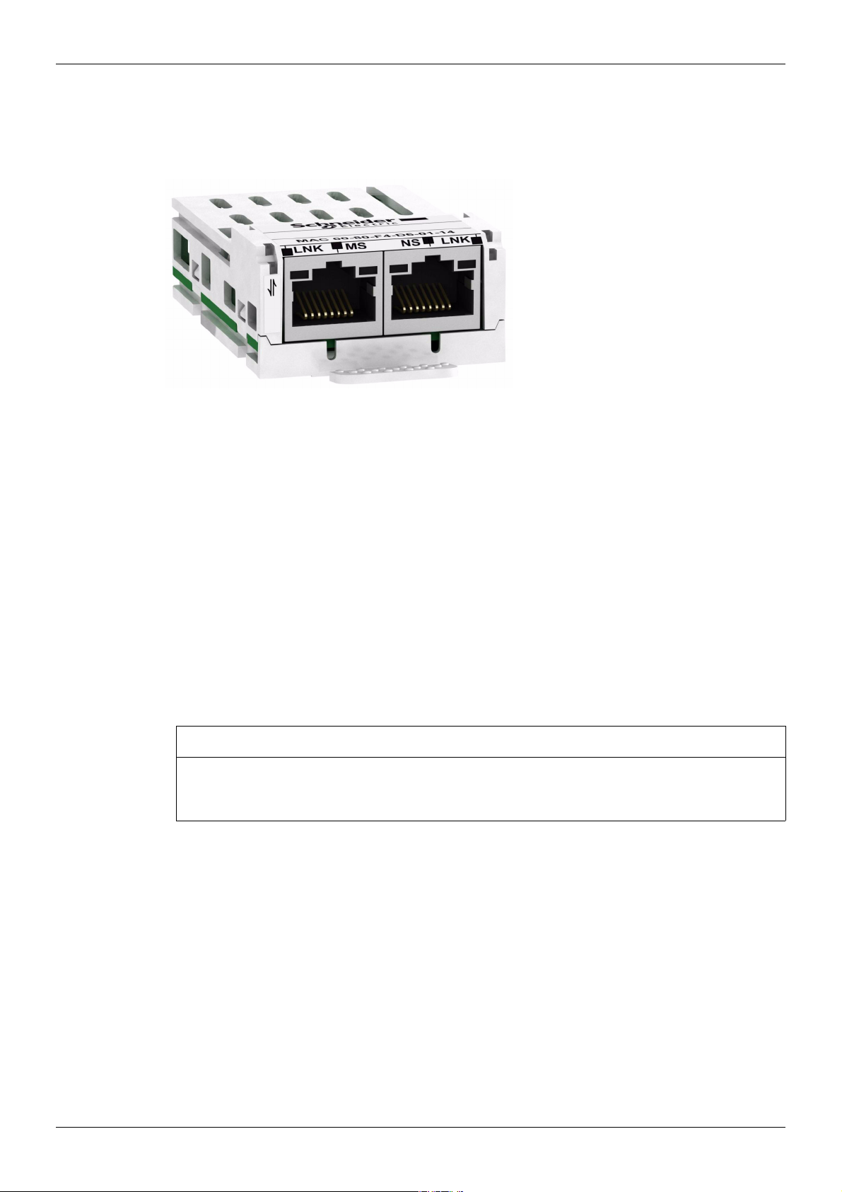
2 RJ45 female sockets
for the PROFINET
connection
The following figure shows the dual RJ45 connector, PROFINET module:
Hardware Setup
Firmware and GSDML Version Compatibility
VW3A3627 option module is compliant with Altivar 32 V1.8 IE11 minimum versions.
Check the firmware version, on the packaging label (on the right part of the label).
The associated GSDML are named as the following example:
GSDML-V2.25-Schneider-ATV32-20130128.xml
The files are available on www.schneider-electric.com.
Installation
Check that the module catalog number marked on the label is the same as that on the delivery note
corresponding to the purchase order.
Remove the communication module from its packaging and check that it has not been damaged in transit.
RISK OF DAMAGE TO THE DRIVE
Install only communication modules designed for ATV32. See catalog numbers in the catalog.
Failure to follow these instructions can result in equipment damage.
NOTICE
14
HRB25668 10/2013
Hardware Setup
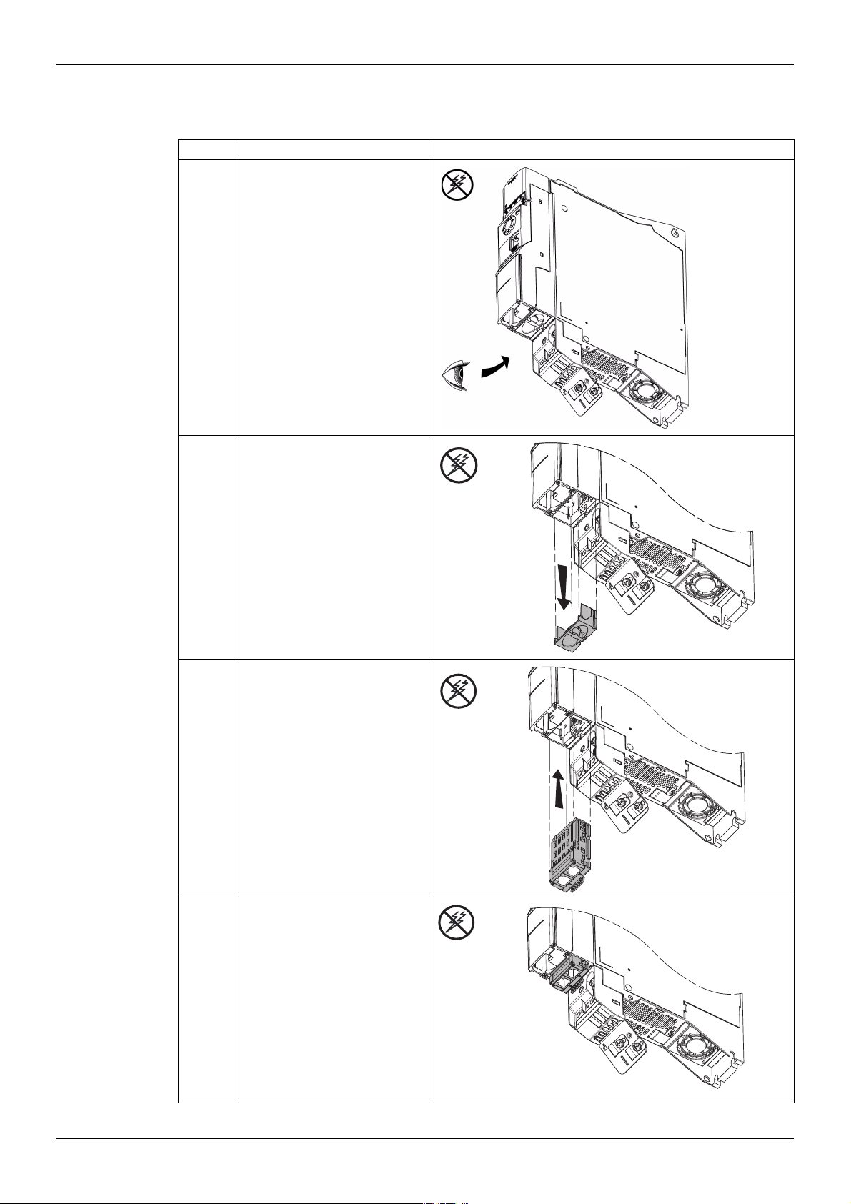
Install the PROFINET module in ATV32
Refer to the installation manual (S1A28686). Install the PROFINET module in ATV32 as follows:Install the
communication module in ATV32 as follows:
Step Action Comment
1 Ensure that the power is off.
Locate the option module port on the
bottom of the ATV32.
2 Extract the cover.
3 Insert the module
4 Check that the module is correctly
inserted and locked mechanically in
the drive.
HRB25668 10/2013 15

Extract the communication module as follows:
Step Action Comment
1 Ensure that the power is off.
Press the strip.
2 Extract the module while maintaining
the strip pressed,
Hardware Setup
16
HRB25668 10/2013

Hardware Setup
Wiring
Cable specifications
The VW3A3627 option module is equipped with 2 RJ45 female sockets for the PROFINET connection.
• Minimum Cat 5e,
• Use equipotential bonding conductors (100 BASE-TX, Category 5e or Industrial Ethernet fast connect)
• Connector RJ45, no crossover cable
• Shield: both ends grounded
• Twisted-pair cable
• Verify that wiring, cables, and connected interfaces meet the PELV requirements.
• Maximum cable length per segment = 100 m (328 ft) / 6 plugs
The following table describes the pin out of each RJ45:
Pin Signal Meaning
1 Tx+ Ethernet transmit line +
2 Tx– Ethernet transmit line –
3 Rx+ Ethernet receive line +
4––
5––
6 Rx– Ethernet receive line –
7––
8––
HRB25668 10/2013 17

Installation Topology
MRP
manager
The VW3A3627 option module, with its 2 RJ45 connector, enables several wiring solutions:
Daisy Chain and/or Star topology
Ring topology
Hardware Setup
PROFINET
SWITCH
The ring topology can only be used with a Media Redundancy Protocol (MRP) capable managed device.
The bus watchdog shall be increased when using MRP function in order to avoid untimely [Com. network]
(CnF) trip.
18
HRB25668 10/2013

Configuration and Parameters
Configuration and Parameters
Overview
This chapter describes the parameters of the VW3A3627 module. These parameters are described here
according to the local HMI or the Graphic keypad. These settings are also possible from SoMove or from the
embedded Web server.
What Is in this Chapter?
This chapter contains the following topics:
Network Settings 20
iPar Settings 22
Modbus TCP Settings 23
3
Topic Page
HRB25668 10/2013 19

Network Settings
Configuration and Parameters
The parameters are accessible in the [CONFIGURATION] (COnF), [FULL] (FULL),
[COMMUNICATION] (COM-) menu and [COMMUNICATION CARD] (Cbd-) submenu.
Parameter Description
(HMI mnemonic)
[DEVICE NAME] (PAn) 16 characters maxi. – [–] - R/W 3340
[IP mode] (IpM)
Use this parameter to select the IP
address assignment method.
[IP card] (IPC- )
(IPC1) (IPC2) (IPC3) (IPC4)
These fields are editable when IP
mode is set to Fixed address
[IP Mask] (IPM-)
(IPM1) (IPM2) (IPM3) (IPM4)
These fields are editable when IP
mode is set to Fixed address
[IP Gate] (IPG-)
(IPG1) (IPG2) (IPG3) (IPG4)
These fields are editable when IP
mode is set to Fixed address
[Network error] (Err)
Ethernet Error Code
[SERVICES] (EWE-)
Enable web services
[PPO profile used] (PrFL)
Actual profile
[MAC @] (MAC)
MAC ad
Displays MAC addresses of the
device.
dress d
isplay
Range or Listed Values Default Long
Name
0: Man
2: DHCP
3: DCP
0 to 255 for each of the 4 fields 0.0.0.0 [0.0.0.0] 0
0 to 255 for each of the 4 fields 0.0.0.0 [255.255.254.0] 255
0 to 255 for each of the 4 fields 0.0.0.0 [0.0.0.0] 0
0: No error
1: PROFINET I/O timeout
2: Network overload
3: Loss of Ethernet Carrier
9: Duplicated IP address.
10: No valid IP.
12: IPAR unconfigured state
13: IPAR unrecoverable error
17: Application I/O configuration error
0: No web services
1: Web server enabled
0: UNCFG
1: Profidrive
100: Device specif
[xx-xx-xx-XX-XX-XX] – [xx-xx-xx-XX-
Man [fixed]
[DHCP]
[DCP]
0 – – R 64270
1– – R/W–
0 [0] 0 R/W 6665
XX-XX]
Short
Name
MAnU
dHCP
dCP
0
0
0
255
254
0
0
0
0
–––
Access Parameter
Number
to
3347
R/W 64250
R/W 64212
64213
64214
64215
R/W 64216
64217
64218
64219
R/W 64220
64221
64222
64223
Left port MAC address is +1.
Right port MAC address is + 2.
If the IP address is not set to a valid value at first power-on, the drive will trip in EPF2.
Assigning IP parameters
The drive needs 3 IP parameters:
• The drive IP address.
• The subnet mask.
• The gateway IP address.
These IP addresses can be entered directly:
If [IP mode] (IpM) is set to [fixed] (MAnU). Using the integrated display terminal, using the graphic display
terminal, or using the SoMove software.
They can be provided by either:
• A DHCP server (correspondence between the Device name and the IP addresses).
• A DCP (Discovery Control Protocol) protocol to discover PROFINET devices.
20
HRB25668 10/2013

Configuration and Parameters
Entering IP parameters in the Terminal
In the [CONFIGURATION] (COnF), [FULL] (FULL), [COMMUNICATION] (COM-) menu and
[COMMUNICATION CARD] (Cbd-) submenu, enter the following IP parameters:
• [IP card] (IPC1) (IPC2) (IPC3) (IPC4),
• [IP Mask] (IPM1) (IPM2) (IPM3) (IPM4),
• [IP Gate] (IPG1) (IPG2) (IPG3) (IPG4).
Turn off the drive and then back on again (control voltage if a separate power supply is being used), otherwise
the IP parameters are not taken into account.
If this address is modified, the new IP address entered is displayed. This IP address will be effective the next
time the drive is turned on.
Case of manual switching of [IP mode] (IPMode)
1. When switching [IP mode] (IPMode) to [DCP] (dCP)
- IP Settings are no longer editable
- Turn off the drive supply and then back on again, including control voltage if a separate power supply
is being used
- The new configuration is applied, the device is waiting for IP settings from PROFINET controller
2. When switching [IP mode] (IPMode) to [Manual] (Manu)
- IP Settings becomes editable
- Set IP settings with valid values
- Turn off the drive and then back on again, including control voltage if a separate power supply is being
used
- The new configuration is applied
Note: If IP settings are not valid, the drive will trip in EPF2 after next power-on.
3. When switching [IP mode] (IPMode) to [DHCP] (dHCP)
- IP Settings are no longer editable.
- Set the Device Name with a valid value.
- Turn off the drive and then back on again, including control voltage if a separate power supply is being
used.
- The new configuration is applied, the device is waiting for IP settings from DHCP Server.
Note: If the Device Name is not valid, the drive will trip in EPF2 after next power-on.
Case of automatic switching of [IP mode] (IPMode) to [DCP] (dCP)
Needed conditions:
- The device has a Station Name configured and validated
- The device is connected to a PROFINET controller
- The PROFINET controller has the Station Name in its own configuration
- The settings are in local configuration of the PROFINET controller
If all of these conditions are fulfilled:
- [IP mode] (IPMode) is automatically set to [DCP] (dCP)
- IP settings are replaced by the one set in local PROFINET controller
- The new configuration is applied immediately
HRB25668 10/2013 21

iPar Settings
Configuration and Parameters
These parameters are accessible in the [CONFIGURATION] (COnF), [FULL] (FULL),
[COMMUNICATION] (COM-) menu and [COMMUNICATION CARD] (Cbd-) submenu.
The following table describes the parameters related to the iPar settings server function
Parameter Description
(HMI mnemonic)
[iPar Validation] (IPAU)
Enable iPar service
[iPar Autosave] (IPAS)
Enable iPar autosave service
[iPar timer] (IPAt)
Interval for periodic saving of the
iPar service
[iPar Error Mgt] (IPAF)
Enable iPar detected error
management
[iPar Local Conf] (ICFG)
Selection of local or server
configuration
[iPar Status] (IPAE)
iPar service status
[iPar Error Cod] (IPAd)
Detected error code
Range or Listed Values Default Long
Name
0: no
1: yes
0: no
1: yes
0: no autosave
1 to 9999 (minutes)
0: no
1: yes
0: The drive configuration is downloaded
from the iPar server at Power-onof the drive.
1: The drive configuration is local.
0: idle state
1: initialization
2: configuration
3: ready
4: operational
5: not configured
6: Unrecoverable detected fault state
0: No detected error
1: Stored configuration is not ok
2: No configuration file on the IPAR server or
configuration is not compatible. (Served
configuration is not ok)
3: Detected error connection to the IPAR
configuration file on the server.
4: Detected error writing the configuration file
to the server.
0 [No]
[Yes]
0 [No]
[Yes]
10 – – R/W 64278
1 [No]
[Yes]
0 [No]
[Yes]
[IDLE]
[INIT]
[CONF]
[RDY]
[OPE]
[UCF
[UNR
0 [0]
[1]
[2]
[3]
[4]
G]
EC]
Short
Name
(nO)
(YES)
(nO)
(YES)
(nO)
(YES)
(nO)
(YES)
(IdLE)
(INIt)
(CONF)
(rdY)
(OPE)
(UCFG)
(UrEC)
(0)
(1)
(2)
(3)
(4)
Access Parameter
Number
R/W 64274
R/W 64275
R/W 64277
R/W 64276
R 64279
R 64280
22
HRB25668 10/2013

Configuration and Parameters
Modbus TCP Settings
The Modbus channel is only used for commissioning tools and for embedded Web server
(UnitID 251: Fieldbus module, Unit ID 248: Variable Speed Drive).
Function Name Code Description Remarks
Read Multiple Register 03
Write Single Register 06
Diagnostic 08
Write multiple register 16
Read device Identification 43
Identification
Byte(s) Meaning With the VW3 A3627 PROFINET module
24…23+B Value of object 2 (B ASCII characters) (1) Example: “ATV32HU15M3”
26+B…29+B Value of object 3 (C ASCII characters) Example: “0201” for version 2.1
32+B…31+B+D Value of object 4 (D ASCII characters) (1) Example: “MACHINE 4”
Read Multiple Register Maximum PDU length: 63 words
16#03
Write Single Register –
16#06
Diagnostic –
16#08
Write Multiple Register Maximum PDU length: 63 words
16#10
Schneider Identification (subfunction 14/16#0E)
16#2B
See the table below
0 Function code = 16#2B 16#2B
1 Type of MEI 16#0E
2 ReadDeviceId code 16#01
3 Degree of conformity 16#02
4 Number of additional frames 16#00 (a single frame)
5 Next object ID 16#00
6 Number of objects
3 for Basic
4 for Regular or Extended
7 Object 1 ID 16#00 = Vendor Name
8 Length of object 1 (A) 13
9…21 Value of object 1 (A ASCII characters) “SchneiderElectric”
22 Object 2 ID 16#01 = Product Code
23 Length of object 2 (B) 11 (for the following example only)
24+B Object 3 ID 16#02 = Major.Minor Revision
25+B Length of object 3 (C) 4
30+B Object 4 ID 16#06 = Application Name (2)
31+B Length of object 4 (D) 8 (for the following example only)
For Regular
And
Extended
(1)The length of this field is variable. Use the “Length of object X” field associated with it to determine the length.
(2)In the case of the drive, this data item corresponds to [DEVICE NAME].
The response to a “drive identification” request does not cause an exception response.
HRB25668 10/2013 23

Configuration and Parameters
24
HRB25668 10/2013

Configuration
Configuration
What Is in this Chapter?
This chapter contains the following topics:
Configuring the Control Channel 26
Configuring Monitor Parameters 29
Configuring Communication Interruption Management 30
4
Topic Page
HRB25668 10/2013 25
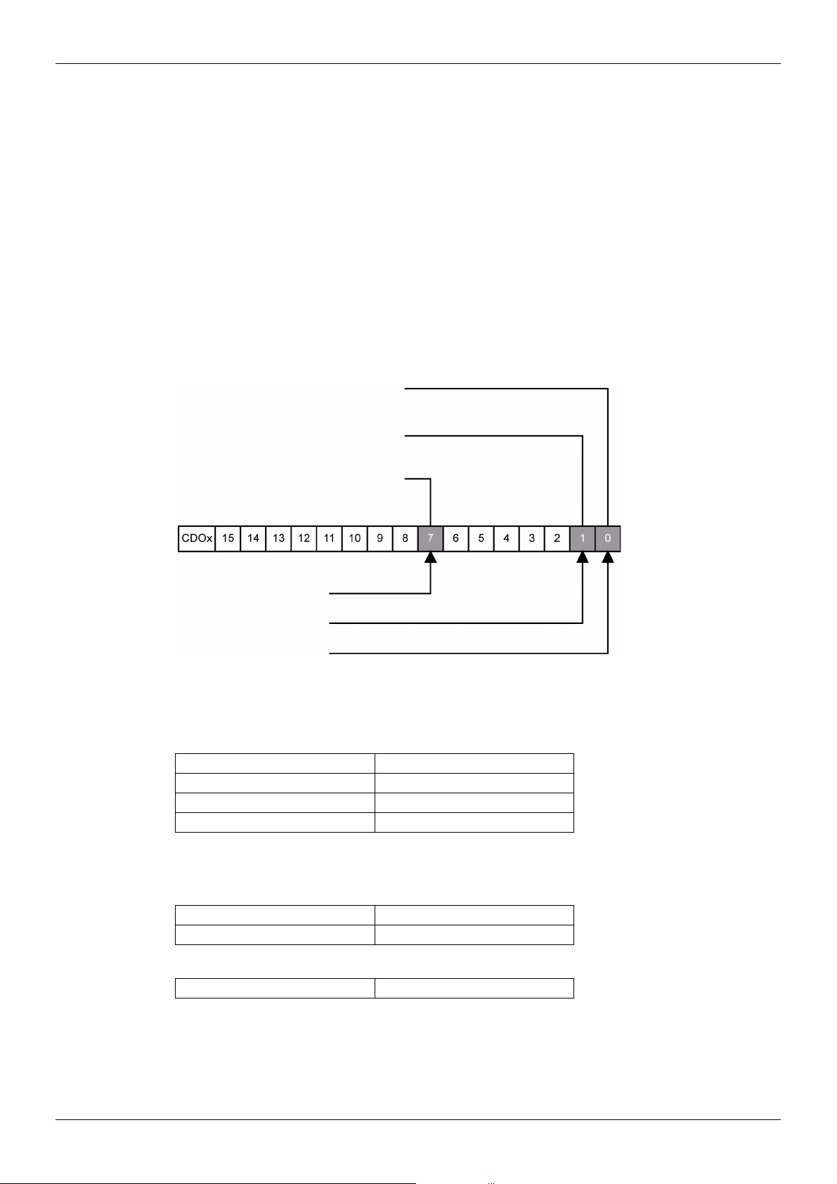
Configuring the Control Channel
Reset
Run reverse
Run forward
[INPUTS / OUTPUTS CFG] /
[Forward] is assigned to CMd bit 0
[INPUTS / OUTPUTS CFG] /
[Reverse assign.] is assigned to
CMd bit 1
[FAULT MANAGEMENT] /
[FAULT RESET] / [Fault reset] is
assigned to CMd bit 7
This chapter explains through 3 examples how to configure the drive for operation from communication
network. Several other combinations are possible. The whole coverage of these possibilities is not in the scope
of this document. For more information, refer to the programming manual.
• I/O Mode - a simple command word (based on forward, reverse, and reset binary commands).
• Combined Mode (with native profile CiA 402) - Both reference and command word come from the
communication network.
• Separate (with native profile CiA 402) - reference and command come from separate sources: for example,
the command (in CiA 402) comes from the communication network and the reference from the HMI.
Configuration of the Drive for Operation in I/O Profile
To illustrate the I/O Profile, here is a simple example, which can be extended with additional features. The
command word is made of Run forward (bit 0 of CMd), run reverse (bit 1 of CMd), and a detected fault reset
(bit 7 of CMd).
Configuration
NOTE: This operating mode is not applicable when the drive is configured from the controller to operate with
the telegram 1 (PROFIdrive).
The settings will be the following:
[Ref.1 channel] (Fr1) [Com. card] (nEt)
[Profile] (CHCF) [I/O profile] (IO)
[Cmd switching] (CCS) Default value
[Cmd channel 1] (Cd1) [Com. card] (nEt)
The bits of the command word can now be configured.
In the [INPUTS / OUTPUTS CFG] menu, configure:
[Forward] (Frd) [Cd00] (Cd00)
[Reverse assign.] (rrS) [Cd01] (Cd01)
In the [FAULT MANAGEMENT] menu, [FAULT RESET] submenu, configure:
[Fault reset] (rSF) [Cd07] (Cd07)
26
HRB25668 10/2013
 Loading...