

Page 1
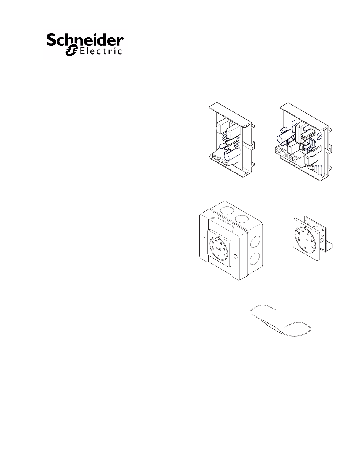
AM-705
AM-703
AM-706
AM-704
AM-708
Applications
The AM-703 span adjustment module changes
non-standard current and volt age sign als into a 2 to 10
Vdc signal.
The AM-704 modulation interface converts signa l input
from a pulse-width modulated input signal to an analog
2 to 10 Vdc signal.
The AM-705 and AM-706 positioners are used for
remotely controlling proportional actuators. The
AM-705 is for surface mounting. The AM-706 is for
flush mounting.
The AM-708 500 ohm resistor converts a 4 to 20 mA
signal to a 2 to 10 Vdc signal.
AM-703, AM-704, AM-705,
AM-706, AM-708
Actuator Accessories for Proportional
Schneider Electric DuraDrive™ Actuators
General Instructions
Features
AM-703
• Zero offset of 0 to 18 Vdc
• S pan range of 2.6 to 17 Vdc
• Will accept 4 to 20 mA signal
AM-704
• Four input pulse clock rates
• Optically isolated input signal
• Linear analog output has 256 steps of resolution
• Diagnostic LEDs
AM-705 and AM-706
• Control range is 0 to 100% of the actuator rotation
angle
• Control signal is switchable from 0 to 10 Vdc to 2 to
10 Vdc
• AM-705 is surface mount, AM-706 is flush mount
AM-708
• Hook up wires are pre-stripped
• Resistor is covered with shrink-wrap tubing
Printed in U.S.A. 4-10 © Copyright 2010 Schneider Electric All Rights Reserved. F-26895-4
Page 2

Applicable Literature
F-Number Description Audience Purpose
F-26645 MS40-7043Series, MS4x-7073 Series,
F-27214 MS41-6043, MS41-6083 Series DuraDrive
F-26748 MS40-717x Series DuraDrive Series Spring
F-26646 Mx4x-6xxx, Mx4x-7xxx Series DuraDrive
MS4x-7153 Series DuraDrive Series Spring
Return Proportional Actuator General
Instructions
Non-Spring Return Direct Coupled Actuator
General instructions
Return Direct Coupled Actuator General
instructions
Actuator Selection Guide
Specifications
AM-703 Power Supply Supply Voltage: 24 Vac ± 15%
Power Consumption <1 Watt Transformer Sizing 1 VA Input Voltage: Max voltage:
Output Voltage: Electrical Connection Wire terminals, 14 gauge max.
Ambient temperature -20 F to 150°F (-30 to 65° C) Humidity 5 to 95% RH non-condensing Mounting Snap-Track (provided) Dimensions Board:
Weight 0.9 oz.
– Sales Personnel
– Application Engineers
– Installers
– Service Personnel
– Start-up Technicians
zero (starting point)
Span adjustment:
Impedence:
0 to 20 mA
Impedence:
Current:
W/ snap-track
Describes the actuator’s features,
specifications, and possible
applications. Provides step-bystep mounting instructions.
24 Vdc ± 15%
25 Vdc 0 to 18 Vdc
2.6 to 17 Vdc 400 Ω
500 Ω 2 to 10 Vdc
15 mA max
1-3/16” x 2-3/16” x 9/16” 1-7/8” x 2-3/8” x 15/16”
2 © Copyright 2010 Schneider Electric All Rights Reserved. F-26895-4
Page 3

AM-704 Power Supply Supply Voltage: 24 Vac ± 15%
Power Consumption <1 Watt Transformer Sizing 2 VA Input
-Isolation
-Type
-Trigger level
-time between trigger pulses
-Impedance
-Pulse duration/resolution
-Range 1
-Range 2
-Range 3
-Range 4 Output Voltage:
Electrical Connection Wire terminals, 14 gauge max. Ambient temperature -20 to 150°F (-30 to 65° C) Operating Humidity 5 to 95% RH non-condensing Mounting Snap-Track (provided) Dimensions Board:
Weight 1.5 oz.
Optically isolated (when wired as such)
Normal or triac, jumper selectable
12 to 24 Vac/Vdc or dry contact to com
12.5 milliseconds minimum Va c - 500 Ω, Vdc - 10 Ω
Four selectable ranges, in seconds or dry contact or SSR closure ± 40% of signal increment
0.0235 to 6 seconds/in 0.0235 sec increments
0.0196 to 5 seconds in 0.0196 sec increments
0.1 to 25.5 seconds/ in 0.100 sec increments
0.59 to 2.93 seconds/ in 0.0092 sec increments Current:
Accuracy:
W/ snap-track
24 Vdc ± 15%
2 to 10 Vdc 15 mA max ± 2%
2-3/16” x 2-3/16” x 9/16” 2-3/8” x 2-1/4” x 15/16”
AM-705, AM-706 Power Supply 24 Vac ± 20%, 50/60 Hz, 24 Vdc ± 10%
Installation
Transformer Sizing 1 VA Control Signal Y 0 to 10 Vdc, 2 to 10 Vdc (switchable) Power Output Up to 10 actuators (1 mA max) Degree of Protection AM-705 only NEMA 4 (IP54) Connection Terminals (14 gauge wire max) Humidity 5 to 95% RH non-condensing
AM-708 Resistance 500 Ω
Length 9"
F-26895-4 © Copyright 2010 Schneider Electric All Rights Reserved. 3
Page 4
AM-703
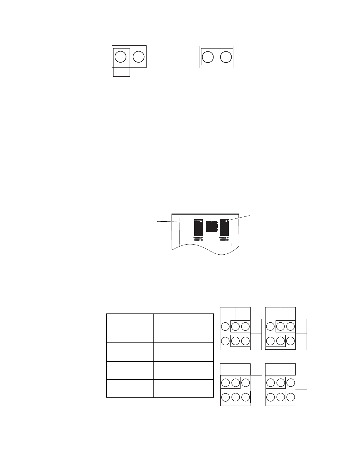
Figure-1 Jumper Settings.
Span Adjustment
Zero Offset
Adjustment
Figure-2 Calibration Adjustments.
Range 1
10
A
B
Range 2
10
A
B
Range 3
10
A
B
Range 3
10
A
B
Position Clock Rate
Range 1
Range 2
Range 3
Range 4
Figure-3 Timing Jumper Settings.
0.0235 to 6 seconds in
0.0235 sec. increments
0.0196 to 5 seconds in
0.0196 sec. increments
0.1 to 25.5 seconds in
0.100 sec. increments
0.59 to 2.93 seconds in
0.0092 sec. increments
Set the circuit board jumper to fit the application.
Jumper not
connected to
both pins for
voltage applications
(as shipped)
Jumper on both
pins for
4 to 20 mA
applications
The AM-703 may also be used to sequence several actuators from one signal source. This
is done by adjusting multiple modules to work at different input ranges. (Example: 2 to 5 Vdc,
5 to 8 Vdc, 8 to 11 Vdc, etc.)
Calibration
1. Attach a variable signal source to the AM-703 input and power wires.
2. Apply power.
3. Input the minimum signal level.
4. Adjust the offset potentiometer to produce a 2 Vdc signal at the output. A clockwise rotation of the potentiometer screw will increase the output signal. See Figure-2.
5. Input the maximum signal level.
6. Adjust the span adjustment to produce a 10 Vdc signal at the output. A clockwise rotation of the potentiometer screw will increase the output signal. See Figure-2.
7. Double check the input-output calibration and install.
AM-704
1. Set the input pulse timing jumpers.
4 © Copyright 2010 Schneider Electric All Rights Reserved. F-26895-4
Page 5
2. Set input jumper for normal or triac.
N O T E
N
O
R
M
A
L
T
R
I
A
C
P
2
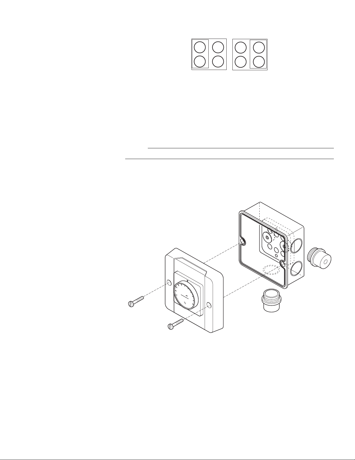
Figure-4 Input Jumper Settings.
100
80
60
40
20
0
BELIMO
Figure-5 AM-705 Mounting.
Do not move the adjustment screws for zero and span.
AM-705
1. Remove the two screws from the front cover.
2. Remove the front cover and position rear cover for mounting.
the rear cover (Figure-6).
4. Punch out a plug to route wiring into box. Two screw-in caps are provided.
5. Connect wires (Figure-13) and set output switch to either 2 to 10 Vdc or 0 to 10 Vdc (Figure-8).
6. Secure front cover with screws removed in step one.
3. Use two mounting screws (customer supplied) and appropriate drill to drill and mount
F-26895-4 © Copyright 2010 Schneider Electric All Rights Reserved. 5
Page 6
1 7/16
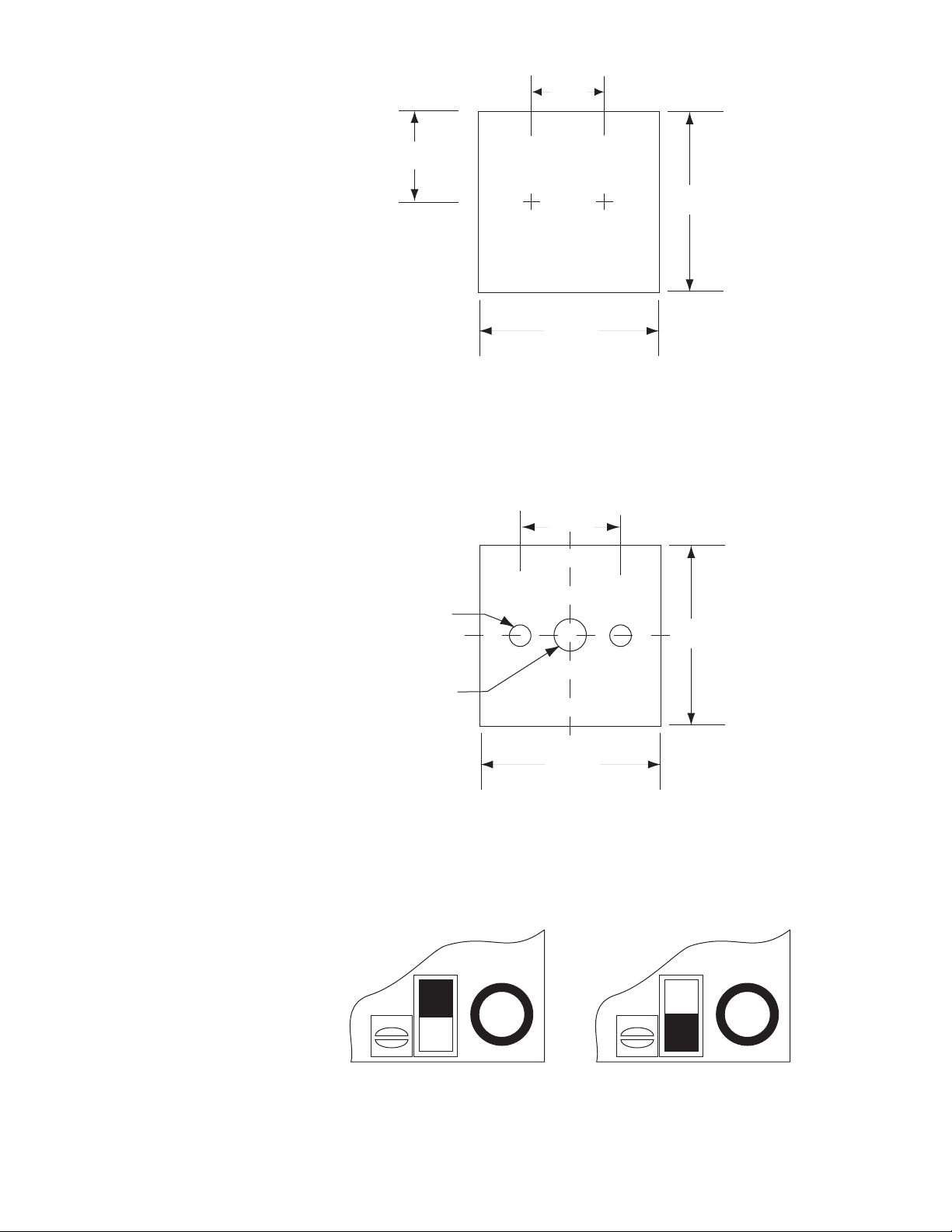
Figure-6 AM-705 Mounting Dimensions.
1/4 (6.4) Dia.
.136 (3.4) Dia.
1 7/8 (48)
1 7/8 (48)
1.10 (28)
Figure-7 AM-706 Mounting Dimensions.
Figure-8 AM-706 Output Switch Settings.
(37)
1.62
(41)
3 1/4 (83)
AM-706
To mount the AM-706 positioner use the following dimensions:
3 1/4 (83)
6 © Copyright 2010 Schneider Electric All Rights Reserved. F-26895-4
1. Drill the three holes (Figure- 7 ).
2. Set the output to 2 to 10 Vdc or 0 to 10 Vdc (Figure-8).
Y = 2 to 10 Vdc Y = 0 to 10 Vdc
Page 7
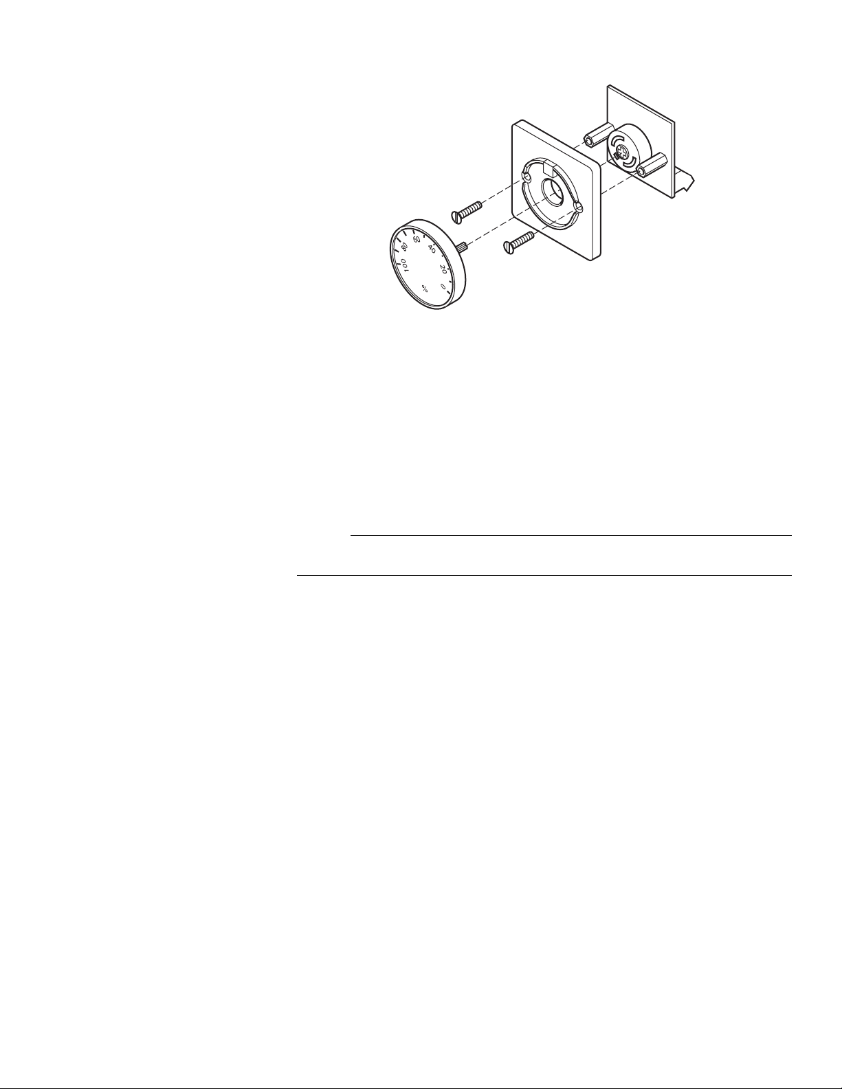
3. Rotate the dial until the percent sign is at the bottom. Pry the dial out with a flat
N O T E
Figure-9 AM-706 Mounting.
screwdriver. A slot at the top of the dial is provided.
4. Remove the two screws from the front cover plate and separate the cover from the circuit board (Figure-9).
5. Position the circuit board behind the mounting surface. The wire screw terminals should be at the bottom.
6. Position the front cover plate and secure it to the circuit board with the two screws removed in step 4.
The dial has a sealing O-ring for moisture resistance. A thin gasket may be placed between
the front cover plate and the mounting surface.
7. Connect wires (Figure-13).
AM-708
The wires of the AM-708 can be attached using whatever means is acceptable to the
application. This includes: wire nuts, soldering, crimp connections and screw terminals.
F-26895-4 © Copyright 2010 Schneider Electric All Rights Reserved. 7
Page 8
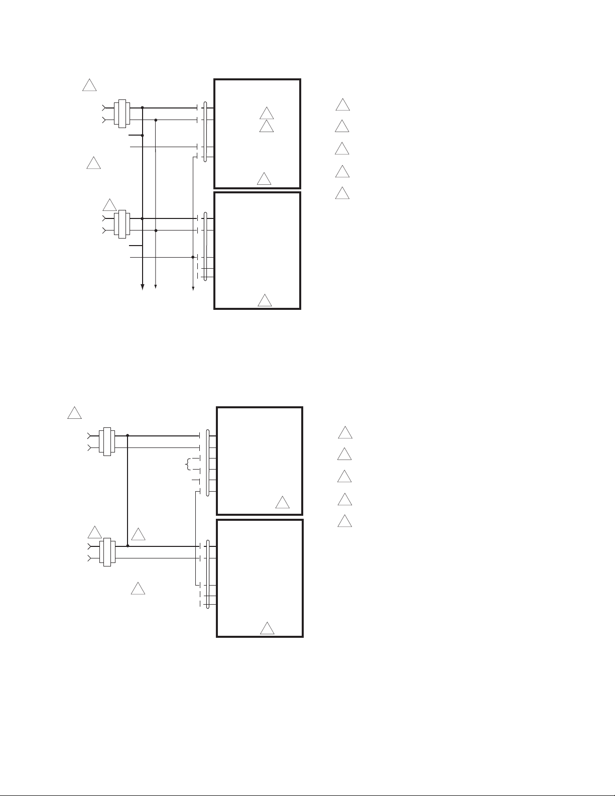
Wiring Diagrams
24 Vac
Transformer
4
Common
1
(1)
(2)
Line
Volts
(3)
(4)
3
4
1 Provide overload protection and disconnect
as required.
2 The controller should be powered from a
separate transformer
3 the actuator and AM-703 may be powered
from the same transformer.
4 Consult controller instruction manual for
more detailed installation information.
5 To reverse control rotation, use the
reversing switch.
+ Hot
Signal Input
Output, 2 to 10 Vdc
(-)
(+)
Control
Signal
Common
2
(1)
(2)
Line
Volts
(3)
(4)
To other
actuators
1
5
+ Hot
Y
Y
(-)
(+)
1
2
(5)
U
AM-703
Proportional
Actuator
Figure-10 AM-703 Wiring Diagram.
24 Vac
Transformer
Common
1
(1)
(2)
Line
Volts
(3)
(4)
3
1 Provide overload protection and disconnect
as required.
2 The actuator and controller must have
separate transformers
3 Consult controller instruction manual for
more detailed installation information.
4 The actuator and AM-704 may be powered
from the same transformer.
5 To reverse control rotation, use the
reversing switch.
+ Hot
+ Signal Input
Output, 0 to 10 Vdc
(-)
(+)
Control
Signal
Common
1
(1)
(2)
Line
Volts
(3)
(4)
5
4
+ Hot
Y
Y
1
2
(5)
U
(5)
(6)
Aux. Power Output
- Signal Input
See control
interface
diagrams
below
2
AM-704
Proportional
Actuator
Figure-11 AM-704 Wiring Diagram.
8 © Copyright 2010 Schneider Electric All Rights Reserved. F-26895-4
Page 9
Line
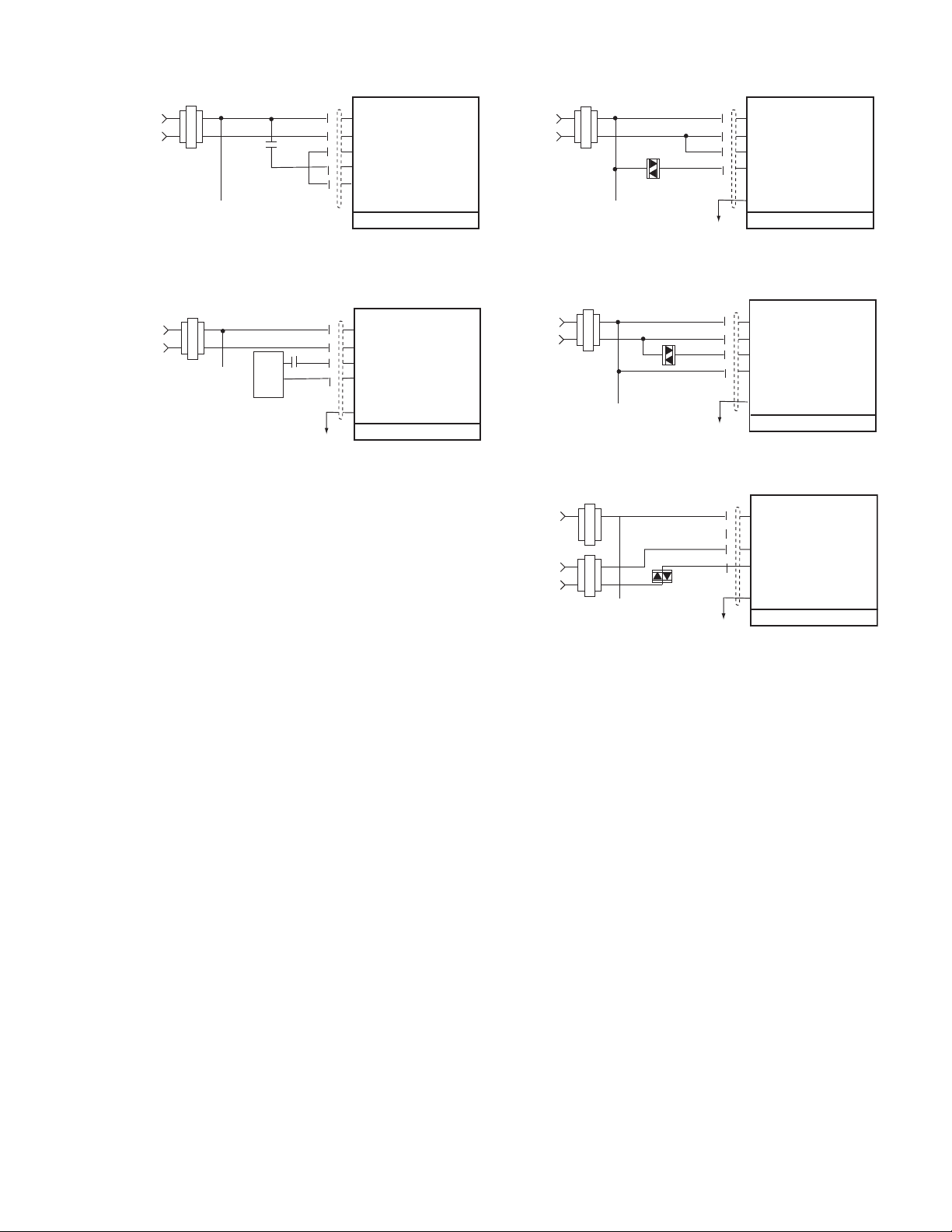
Figure-12 AM-704 Control Interface.
Volts
24 Vac
Transformer
N.O.
Common(1)
+ Hot
(2)
+ Signal Input
(3)
(4)
- Signal Input
Aux Power Output
(5)
(6)
Line
Volts
24 Vac
Transformer
(2)
(3)
(4)
(5)
(6)
Common(1)
+ Hot
AC
AC
Relay pulsed pulsed signal (non-isolated circuit)
24 Vac
Transformer
Line
Volts
N.O.
Separate power supply
12 to 24 Vdc/Vac
Common(1)
+ Hot
(2)
+ Signal Input
(3)
(4)
- Signal Input
(5)
(6)
Relay pulsed pulsed signal (isolated circuit)
Triac, Common pulsed signal (non-isolated circuit)
24 Vac
Transformer
Line
Volts
(2)
(3)
(4)
(5)
(6)
Common(1)
+ Hot
AC
AC
Triac, hot pulsed signal (non-isolated circuit)
24 Vac
Transformer
Line
Volts
BAS
Power
(2)
(3)
(4)
(5)
(6)
Common(1)
+ Hot
AC
AC
Triac, pulsed signal (isolated circuit)
F-26895-4 © Copyright 2010 Schneider Electric All Rights Reserved. 9
Page 10
24 Vac
Transformer
Common
1
(1)
(2)
Line
Volts
(3)
1 Provide overload protection and disconnect
as required.
2 Override Switches are optional.
+
Common
2
(1)
(2)
(3)
(4)
+
+ Y
+ Z
+ Y
A
B
2
Proportional Actuator
AM-705, AM-706
24 Vac
Transformer
Common
1
(1)
(2)
Line
Volts
(3)
+
(-)
(+)
0 to 10 Vdc
Control Signal
Common(1)
(2)
(3)
(4)
+
+ Y
+ Z
+ Y
AM-705, AM-706
Proportional Actuator
A B Damper Control
off
off
on
on
off
on
off
on
0%
0%
0 to 100%
100%
Minimum Position Setting
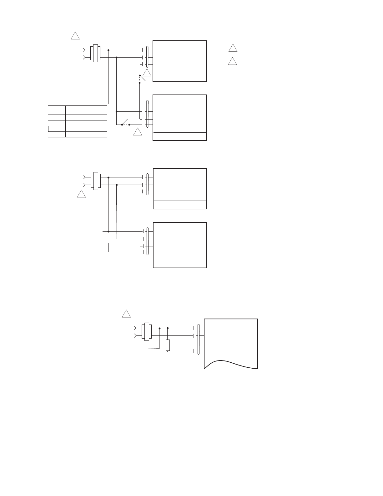
Figure-13 AM-705 and AM-706 Wiring Diagram.
24 Vac
Transformer
Common
1
(1)
(2)
Line
Volts
(3)
+
Y1 Input, 0 to 10 V
AM-708
Figure-14 AM-708 Wiring Diagram.
10 © Copyright 2010 Schneider Electric All Rights Reserved. F-26895-4
Page 11
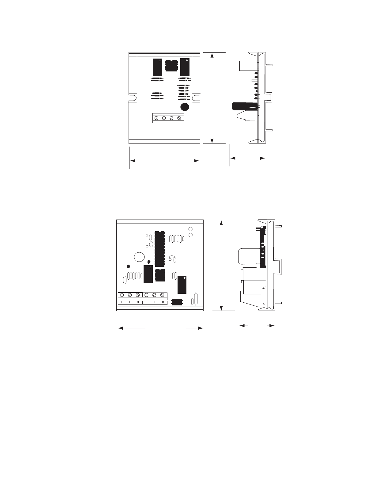
Dimensions
Figure-15 AM-703 Dimensions.
2 1/4" (57 mm)
2 3/8"
(51 mm)
1"
(25 mm)
1 2 3 4 5 6
Figure-16 AM-704 Dimensions.
2 3/8"
(51 mm)
1 2 3 4
1 7/8" (48 mm)
15/16"
(24 mm)
F-26895-4 © Copyright 2010 Schneider Electric All Rights Reserved. 11
Page 12
On October 1st, 2009, TAC became the Buildings business of its parent company Schneider Electric. This document reflects the visual identi ty of Schneider Electric,
ho wever there r em ains references to TAC as a corporate brand in the body copy. As each document is updated, the body co py will be changed to r efl ect app ropriate
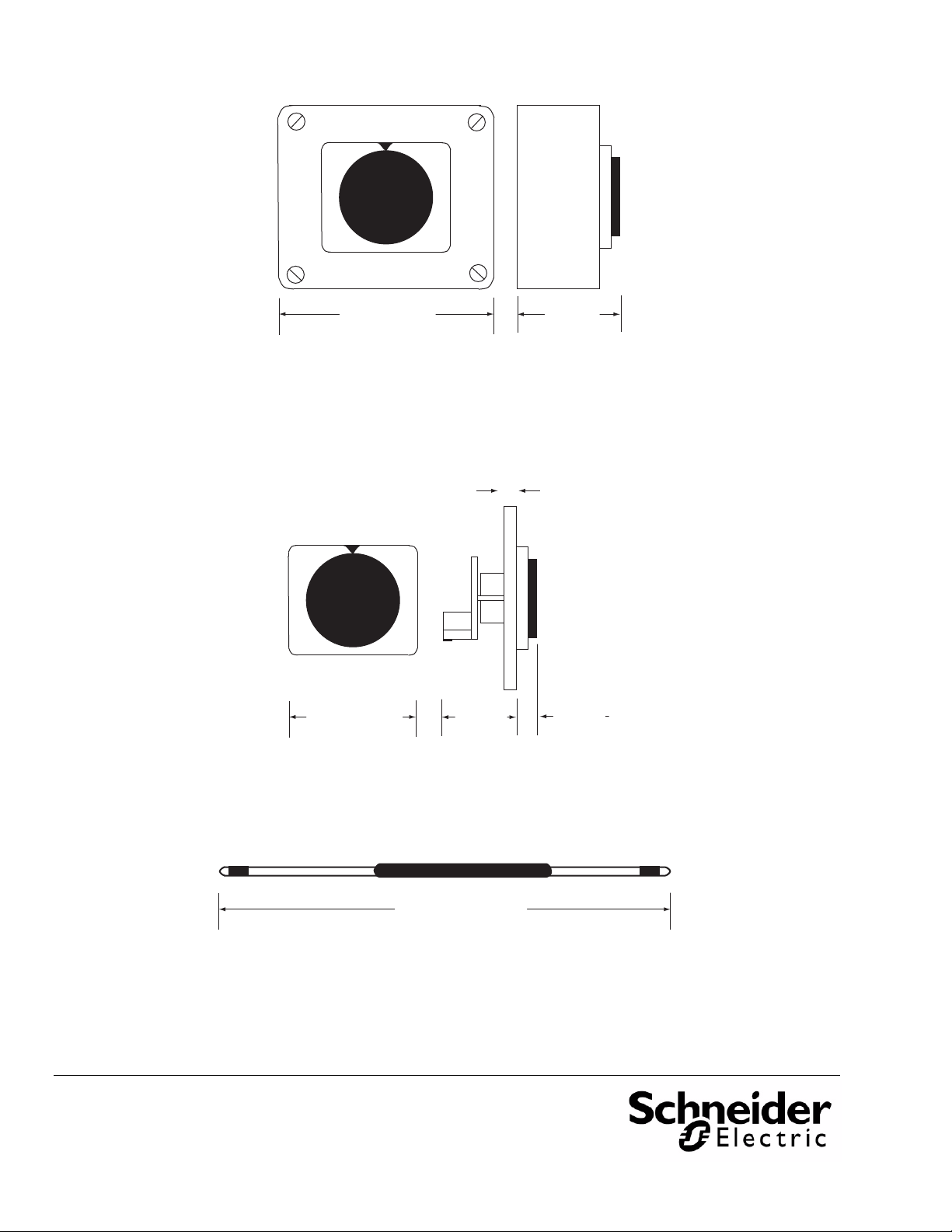
g
3 5/16" (84 mm)
Figure-17 AM-705 Dimensions.
1 7/8" (48 mm)
11/16"
(27 mm)
1.4"
(6 mm)
SQ
3/64 to 13/64"
(1 to 5 mm)
Panel Thickness
Figure-18 AM-706 Dimensions.
Approx. 9" (229 mm)
Figure-19 AM-708 Dimensions.
2 5/16"
(59.5 mm)
corporate brand chan
Copyright 2010, Schneider Electric
All brand names, trademarks and registered
trademarks are the property of their respective
owners. Information contained within this
document is subject to change without notice.
F-26895-4
es.
Schneider Electric
1354 Clifford Avenue
P.O. Box 2940
Loves Park, IL 61132-2940
www.schneider-electric.com/buildings
 Loading...