

Page 1

Application
To provide 24 Vac power to components such as
actuators and controllers.
Features
• Meets NEC Class 2 requirements
• 120/208/240 Vac multiple primary
AM-610
Transformer
General Instructions
• Color coded leads
Applicable Literature
• Cross-Reference Guide, F-23638
• Reference Manual, F-12683
• Application Manual, F-21335
Printed in U.S.A. 4/10 © Copyright 2010 Schneider Electric All Rights Reserved. F-24859-3
Page 2

SPECIFICATIONS
Transformer Inputs
Environment
INSTALLATION
Inspection
Voltage and Current Ratings:
Primary, 120/208/240 volts, 50/60Hz.
Secondary, 24 Vac, 40 VA.
Leads: 7" (178 mm) long, #18 GA. stranded wire.
Rating: NEC Class 2.
Mounting: 1/2"-14 standard straight pipe thread conduit nipple.
Ambient Temperature Limits:
Shipping and Storage, -40 to 160°F (-40 to 71°C).
Operating, -40 to 140°F (-40 to 60°C).
Location: NEMA Type 1.
Inspect the package for damage. If damaged, notify the appropriate carrier immediately. If undamaged, open the package and inspect the device for obvious damage. Return damaged products.
Requirements
• Tools (not provided):
Volt-ohm Meter (VOM)
Appropriate screwdriver for mounting screws and terminal connections
• Training: Installer must be a qualified, experienced technician.
WARNING
• Avoid locations where excessive moisture, corrosive fumes or vibration are present.
• Make all connections in accordance with the wiring table (Table-1) and in accordance with
national and local electrical codes. Use No. 18 AWG or larger copper conductors only.
CAUTION
• Do not exceed ratings of the device.
2 © Copyright 2010 Schneider Electric All Rights Reserved. F-24859-3
Page 3
Mounting
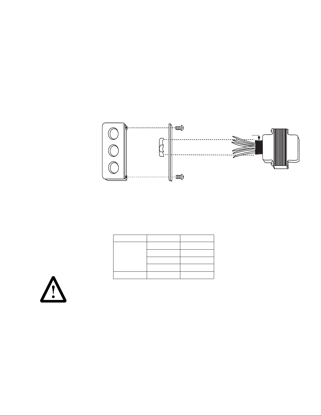
Figure-1 AM-610 Conduit Box Assembly.
4 x 4 conduit box
screw
conduit nipple
AM-610
screw
conduit lock
nut for AM-610
conduit box
cover plate
insert AM-610 conduit nipple
through cover plate knockout
Mount AM-610 transformer to 4" X 4" conduit box by referring to Figure-1, and using the following procedure:
1. Remove lock nut from conduit nipple on transformer.
2. Remove the cover plate of the conduit box.
3. Insert the transformer conduit nipple into cover plate knockout.
4. Replace lock nut and tighten to secure transformer to the cover plate.
5. Proceed with transformer wiring (refer to the Wiring Section Table-1 for lead descriptions).
6. Tape off all unused wire leads.
Wiring
Table-1 Transformer Power Lead Selection.
WARNING
Tape unused power wires. Injury may occur if bare wires are not taped off.
Rating Selection Color
120 volts White
Primary
Secondary 24 volts Brown
208 volts Red/Yellow
240 volts Orange
Common Black
F-24859-3 © Copyright 2010 Schneider Electric All Rights Reserved. 3
Page 4
On Oc tober 1st, 2009, TA C becam e the Buildings busi n ess of its par ent company Schneider Electric. Thi s document reflects the visu al identity of Schneider Electri c,
ho wever t he re remains refer ences to TAC as a corporate brand i n the body copy. As each document is updated, the body copy will be changed to reflect appropri ate
DIMENSIONAL DATA
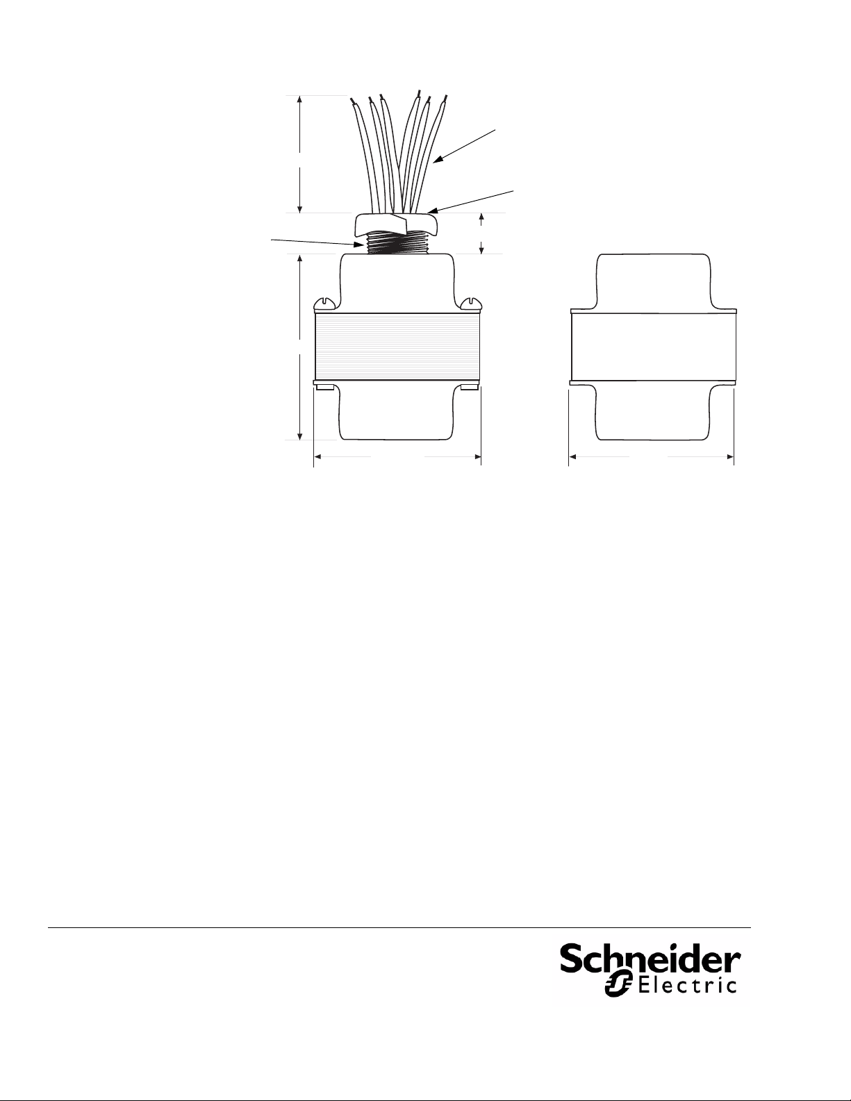
Power Leads
Lock Nut
Conduit Nipple
7"
2-1/2"
2-3/16" 2-5/8"
Figure-2 AM-610 Transformer.
1/2"
(64 mm)
(178 mm)
(13 mm)
(56 mm) (67 mm)
corpor ate br a nd changes.
Copyright 2010, Schneider Electric
All brand names, trademarks and registered
trademarks are the property of their respective
owners. Information contained within this
document is subject to change without notice.
F-24859-3
 Loading...