

Page 1

Altivar Library
SoMachine
Function blocks
Software manual
V2.08, 04.2011
0198441113880, V2.08, 04.2011
www.schneider-electric.com
Page 2

Important information Altivar Library
Important information
This manual is part of the product.
Carefully read this manual and observe all instructions.
Keep this manual for future reference.
Hand this manual and all other pertinent product documentation over
to all users of the product.
Carefully read and observe all safety instructions and the chapter
"Before you begin - safety information".
Some products are not available in all countries.
For information on the availability of products, please consult the catalog.
Subject to technical modifications without notice.
All details provided are technical data which do not constitute warranted qualities.
Most of the product designations are registered trademarks of their
respective owners, even if this is not explicitly indicated.
2 Function blocks
0198441113880, V2.08, 04.2011
Page 3

Altivar Library Table of contents
Table of contents
Important information 2
Table of contents 3
About this manual 7
1 Before you begin - safety information 9
1.1 Qualification of personnel 9
1.2 Intended use 9
1.3 Hazard categories 10
1.4 Basic information 11
1.5 Standards and terminology 12
2 Altivar Library Guide 13
2.1 List of the function blocks 14
2.2 Basic inputs and outputs 17
2.2.1 Signal behavior of function blocks with the input Enable 19
2.2.2 Signal behavior of function blocks with the input Execute 21
2.3 Single axis 23
2.3.1 Initialization 23
2.3.1.1 MC_Power_ATV 23
2.3.2 Operating mode Jog 24
2.3.2.1 MC_Jog_ATV 24
2.3.3 Operating mode Speed Control 26
2.3.3.1 VelocityControlAnalogInput_ATV 26
2.3.3.2 VelocityControlSelectAI_ATV 27
2.3.4 Operating mode Profile Velocity 28
2.3.4.1 MC_MoveVelocity_ATV 28
2.3.5 Stopping 29
2.3.5.1 MC_Stop_ATV 29
2.4 Administrative 30
2.4.1 Reading a parameter 30
2.4.1.1 MC_ReadActualVelocity_ATV 30
2.4.1.2 MC_ReadActualTorque_ATV 31
2.4.1.3 MC_ReadStatus_ATV 32
2.4.1.4 MC_ReadParameter_ATV 34
2.4.1.5 GetSupplierVersion 35
2.4.2 Writing a parameter 36
2.4.2.1 MC_WriteParameter_ATV 36
2.4.2.2 SetDriveRamp_ATV 37
2.4.2.3 SetFrequencyRange_ATV 38
2.4.2.4 ResetParameters_ATV 39
0198441113880, V2.08, 04.2011
Function blocks 3
Page 4

Table of contents Altivar Library
2.4.2.5 StoreParameters_ATV 40
2.4.3 Saving and restoring device configuration 41
2.4.3.1 UploadDriveParameter_ATV 41
2.4.3.2 DownloadDriveParameter_ATV 42
2.4.4 Inputs and outputs 43
2.4.4.1 ReadAnalogInput_ATV 43
2.4.4.2 MC_ReadDigitalInput_ATV 44
2.4.4.3 MC_ReadDigitalOutput_ATV 46
2.4.4.4 MC_WriteDigitalOutput_ATV 48
2.4.5 Error handling 49
2.4.5.1 MC_ReadAxisError_ATV 49
2.4.5.2 MC_Reset_ATV 53
2.5 Device Function 54
2.5.1 Startup 54
2.5.1.1 Altivar_Startup 54
2.5.2 Control 63
2.5.2.1 Altivar31_Control 63
2.5.2.2 Altivar71_Control 72
2.5.2.3 Altivar32_Control 81
3 Glossary 93
3.1 Units and conversion tables 93
3.1.1 Length 93
3.1.2 Mass 93
3.1.3 Force 93
3.1.4 Power 93
3.1.5 Rotation 94
3.1.6 Torque 94
3.1.7 Moment of inertia 94
3.1.8 Temperature 94
3.1.9 Conductor cross section 94
3.2 Terms and Abbreviations 95
4 Index 97
4 Function blocks
0198441113880, V2.08, 04.2011
Page 5

Altivar Library
0198441113880, V2.08, 04.2011
Function blocks 5
Page 6

Altivar Library
6 Function blocks
0198441113880, V2.08, 04.2011
Page 7

Altivar Library
About this manual
Purpose of this document
Validity note
About this manual
This manual is an extract of the SoMachine Online Help. Fully read
and understand all manuals of the SoMachine Online Help and of the
products used.
This document describes the functions of the Altivar Library.
Software environment Devices Fieldbus
SoMachine
Device Descriptions of version 4.0.0.0 and higher are
supported.
ATV31/ATV312
ATV71/ATV32
CANopen
This document is valid for SoMachine as of Version 2.0.
Source manuals The latest versions of the manuals can be downloaded from the Inter-
net at:
http://www.schneider-electric.com
Corrections and suggestions We always try to further optimize our manuals. We welcome your sug-
gestions and corrections.
Please get in touch with us by e-mail:
techcomm@schneider-electric.com.
Work steps If work steps must be performed consecutively, this sequence of steps
is represented as follows:
■
Special prerequisites for the following work steps
▶
Step 1
◁
Specific response to this work step
▶
Step 2
If a response to a work step is indicated, this allows you to verify that
the work step has been performed correctly.
Unless otherwise stated, the individual steps must be performed in the
specified sequence.
SI units SI units are the original values. Converted units are shown in brackets
behind the original value; they may be rounded.
Example:
Minimum conductor cross section: 1.5 mm2 (AWG 14)
Glossary Explanations of special technical terms and abbreviations.
Index List of keywords with references to the corresponding page numbers.
0198441113880, V2.08, 04.2011
Function blocks 7
Page 8

About this manual
Altivar Library
Disclaimer The information provided in this documentation contains general
descriptions and/or technical characteristics of the performance of the
products described here. This documentation is not intended as a
substitute for and is not to be used for determining suitability or reliability of these products for specific user applications. It is the duty of
any user or integrator to perform the appropriate and fully comprehensive risk analyses, evaluation and testing of the products with respect
to the relevant specific application or use of the products. Neither
Schneider Electric nor any of its affiliate or subsidiaries shall be
responsible or liable for misuse of the information contained herein. If
you have any suggestions for improvements or amendments or have
found errors in this publication, please notify us.
No part of this document may be reproduced in any form or by any
means, electronic or mechanical, including photocopying, without
express written permission of Schneider Electric.
All pertinent state, regional, and local safety regulations must be
observed when installing and using this product. For reasons of safety
and to help ensure compliance with documented system data, only
the manufacturer should perform repairs to components.
When devices are used for applications with technical safety requirements, the relevant instructions must be followed.
Failure to use Schneider Electric software or approved software with
our hardware products may result in injury, harm, or improper operating results.
Failure to observe this information can result in injury or equipment
damage.
8 Function blocks
0198441113880, V2.08, 04.2011
Page 9

Altivar Library
1 Before you begin - safety information
1 Before you begin - safety information
1.1 Qualification of personnel
Only appropriately trained persons who are familiar with and understand the contents of this manual and all other pertinent product documentation are authorized to work on and with this product. In addition,
these persons must have received safety training to recognize and
avoid hazards involved. These persons must have sufficient technical
training, knowledge and experience and be able to foresee and detect
potential hazards that may be caused by using the product, by changing the settings and by the mechanical, electrical and electronic equipment of the entire system in which the product is used.
All persons working on and with the product must be fully familiar with
all applicable standards, directives, and accident prevention regulations when performing such work.
1
1.2
Intended use
This product is a library for industrial use with the appropriate controllers and drives.
The product may only be used in compliance with all applicable safety
regulations and directives, the specified requirements and the technical data.
Prior to using the product, you must perform a risk assessment in view
of the planned application. Based on the results, the appropriate
safety measures must be implemented.
Since the product is used as a component in an entire system, you
must ensure the safety of persons by means of the design of this
entire system (for example, machine design).
Any use other than the use explicitly permitted is prohibited and can
result in hazards.
Electrical equipment should be installed, operated, serviced, and
maintained only by qualified personnel.
0198441113880, V2.08, 04.2011
Function blocks 9
Page 10
1 Before you begin - safety information
1.3 Hazard categories
Safety instructions to the user are highlighted by safety alert symbols
in the manual. In addition, labels with symbols and/or instructions are
attached to the product that alert you to potential hazards.
Depending on the seriousness of the hazard, the safety instructions
are divided into 4 hazard categories.
DANGER indicates an imminently hazardous situation, which, if not
avoided, will result in death or serious injury.
WARNING indicates a potentially hazardous situation, which, if not
avoided, can result in death, serious injury, or equipment damage.
CAUTION indicates a potentially hazardous situation, which, if not
avoided, can result in injury or equipment damage.
Altivar Library
DANGER
WARNING
CAUTION
CAUTION
CAUTION used without the safety alert symbol, is used to address
practices not related to personal injury (e.g. can result in equipment
damage).
10 Function blocks
0198441113880, V2.08, 04.2011
Page 11
Altivar Library
1.4 Basic information
1 Before you begin - safety information
WARNING
LOSS OF CONTROL
•
The designer of any control scheme must consider the potential
failure modes of control paths and, for certain critical functions,
provide a means to achieve a safe state during and after a path
failure. Examples of critical control functions are emergency stop,
overtravel stop, power outage and restart.
•
Separate or redundant control paths must be provided for critical
functions.
•
System control paths may include communication links. Consideration must be given to the implication of unanticipated transmission delays or failures of the link.
•
Observe all accident prevention regulations and local safety
guidelines.
•
Each implementation of the product must be individually and thoroughly tested for proper operation before being placed into service.
Failure to follow these instructions can result in death or serious injury.
1)
1)
For USA: Additional information, refer to NEMA ICS 1.1 (latest edition), “Safety
Guidelines for the Application, Installation, and Maintenance of Solid State Control”
and to NEMA ICS 7.1 (latest edition), “Safety Standards for Construction and Guide
for Selection, Installation and Operation of Adjustable-Speed Drive Systems”.
WARNING
UNINTENDED BEHAVIOR DUE TO IMPROPER ERROR HANDLING
Improper error handling can change movements or signals or deactivate monitoring functions.
•
Carefully program the error handling routines.
•
Verify the effectiveness of error handling.
Failure to follow these instructions can result in death, serious
injury or equipment damage.
WARNING
UNINTENDED BEHAVIOR DUE TO CHANGES TO THE LIBRARY
•
Do not change or manipulate the library in any way whatsoever.
Failure to follow these instructions can result in death, serious
injury or equipment damage.
0198441113880, V2.08, 04.2011
Function blocks 11
Page 12

1 Before you begin - safety information
1.5 Standards and terminology
Technical terms, terminology and the corresponding descriptions in
this manual are intended to use the terms or definitions of the pertinent standards.
In the area of drive systems, this includes, but is not limited to, terms
such as "safety function", "safe state", "fault", "fault reset", "failure",
"error", "error message", "warning", "warning message", etc.
Among others, these standards include:
•
IEC 61800 series: "Adjustable speed electrical power drive systems"
•
IEC 61158 series: "Industrial communication networks - Fieldbus
specifications"
•
IEC 61784 series: "Industrial communication networks - Profiles"
•
IEC 61508 series: "Functional safety of electrical/electronic/programmable electronic safety-related systems"
Also see the glossary at the end of this manual.
Altivar Library
12 Function blocks
0198441113880, V2.08, 04.2011
Page 13

Altivar Library
2 Altivar Library Guide
Library name Altivar Library (ATV)
Software environment Devices Fieldbus
SoMachine
Device Descriptions of version 4.0.0.0 and higher are
supported.
The function blocks described here are used to control ATV drives in
CANopen fieldbuses under the SoMachine software environment. The
function blocks are compliant with the IEC 61131-3 standard.
ATV31/ATV312
ATV71/ATV32
2 Altivar Library Guide
2
CANopen
Naming conventions
Simple application
Categorization of the function
blocks
Preparing the drive Before you can access the drive via CANopen or CANmotion, you
•
Function blocks with the prefix MC_ ("Motion Control") are compliant with the PLCopen specifications. They conform to a global
standard for programming motion control applications.
•
Function blocks without a prefix are vendor-specific (Schneider
Electric); however, they comply with the general PLC open rules.
•
The function blocks are used in the same way.
•
The function blocks comply with the PLCopen state diagram.
•
The function blocks feature a visualization that can be easily integrated into the application.
•
Single axis: These function blocks are used for movements or
functions of a single, independent axis.
•
Administrative: These function blocks are used for configuration
tasks (such as reading and writing of parameters, restoring a
device configuration, etc.).
•
Device Function: These function blocks support you in commissioning a drive at a controller. Before these function blocks can be
used, you must correctly set the communication parameters baud
rate and node address.
must make a number of settings. Among others, these settings
include:
•
Address and baud rate
•
Profile (CHCF) = Separate
•
Reference 1 (Fr1) = CAN
•
Control channel (Cd1) = CAN
•
Control channel switching (CSS) = Cd1
•
Reference switching (rFC) = C214
Note the pertinent information in the product manual.
If you do not know the existing configuration, it may be useful to
restore the factory settings. See "2.4.2.4 ResetParameters_ATV".
0198441113880, V2.08, 04.2011
Function blocks 13
Page 14

2 Altivar Library Guide
2.1 List of the function blocks
Category Single axis
Altivar Library
Category Subcategory Function block Type ATV31/
ATV312
Single axis
Initialization "2.3.1.1
MC_Power_ATV"
Operating mode
Jog
Operating mode
Speed Control
Operating mode
Profile Velocity
Stopping "2.3.5.1
"2.3.2.1
MC_Jog_ATV"
"2.3.3.1 VelocityControlAnalogInput_ATV"
"2.3.3.2 VelocityControlSelectAI_ATV"
"2.3.4.1 MC_MoveVelocity_ATV"
MC_Stop_ATV"
PLCopen X X X
PLCopen X X X
Vendor-specific X X X
Vendor-specific X X X
PLCopen X X X
PLCopen X X X
ATV71 ATV32
14 Function blocks
0198441113880, V2.08, 04.2011
Page 15

Altivar Library
Category Administrative
2 Altivar Library Guide
Category Subcategory Function block Type ATV31/
ATV312
Administrative
Reading a parameter
Writing a parameter "2.4.2.1 MC_Write-
Saving and restoring device configuration
Inputs and outputs "2.4.4.1 ReadAna-
Error handling "2.4.5.1 MC_Read-
"2.4.1.1 MC_ReadActualVelocity_ATV"
"2.4.1.2 MC_ReadActualTorque_ATV"
"2.4.1.3 MC_ReadStatus_ATV"
"2.4.1.4 MC_ReadParameter_ATV"
"2.4.1.5 GetSupplierVersion"
Parameter_ATV"
"2.4.2.2 SetDriveRamp_ATV"
"2.4.2.3 SetFrequencyRange_ATV"
"2.4.2.4 ResetParameters_ATV"
"2.4.2.5 StoreParameters_ATV"
"2.4.3.1 UploadDriveParameter_ATV"
"2.4.3.2 DownloadDriveParameter_ATV"
logInput_ATV"
"2.4.4.2 MC_ReadDigitalInput_ATV"
"2.4.4.3 MC_ReadDigitalOutput_ATV"
"2.4.4.4 MC_WriteDigitalOutput_ATV"
AxisError_ATV"
"2.4.5.2
MC_Reset_ATV"
PLCopen X X X
PLCopen X X X
PLCopen X X X
PLCopen X X X
Vendor-specific X X X
PLCopen X X X
Vendor-specific X X X
Vendor-specific X X X
Vendor-specific X X X
Vendor-specific X X X
Vendor-specific X X X
Vendor-specific X X X
Vendor-specific X X X
PLCopen X X X
PLCopen X X X
PLCopen X X X
PLCopen X X X
PLCopen X X X
ATV71 ATV32
0198441113880, V2.08, 04.2011
Function blocks 15
Page 16

2 Altivar Library Guide
Category Device Function
Altivar Library
Category Subcategory Function block Type ATV31/
ATV312
Device Function
Startup "2.5.1.1 Alti-
var_Startup"
Control "2.5.2.1 Alti-
var31_Control"
"2.5.2.2 Altivar71_Control"
"2.5.2.3 Altivar32_Control"
Vendor-specific X X X
Vendor-specific X - -
Vendor-specific - X -
Vendor-specific - - X
ATV71 ATV32
16 Function blocks
0198441113880, V2.08, 04.2011
Page 17

Altivar Library
2.2 Basic inputs and outputs
Input/output Data type Description
Axis Axis_Ref_ATV
Input Input_Ref_ATV
Output
Input Data type Description
Enable BOOL
Execute
Output_Ref_ATV
BOOL
Name of the axis (instance) for which the function block is to
be executed. The name must be declared in the PLC configuration. The name of the axis can be found to the left in the tree
structure of your software.
Input is a special data type for digital and analog inputs. The
data type corresponds to the name of the axis (instance) to
which the inputs belong (similar to Axis).
In the case of function blocks specifically provided for reading
analog and digital inputs, Input replaces the input Axis.
Output is a special data type for digital and outputs. The data
type corresponds to the name of the axis (instance) to which
the outputs belong (similar to Axis).
In the case of function blocks specifically provided for writing
and reading analog and digital inputs, Output replaces the
input Axis.
Value range: TRUE, FALSE
Initial value: FALSE
The input Enable starts or terminates the execution of a function block. (exception "2.3.1.1 MC_Power_ATV")
FALSE: Execution of the function block is terminated. The outputs Valid, Busy, CommandAborted and Error are set to
FALSE.
TRUE: The function block is executed repeatedly.
Value range: TRUE, FALSE
Initial value: FALSE
The input Execute starts the execution of a function block in
the case of a rising edge (FALSE->TRUE).
If a second rising edge is detected during the execution of the
function block, the current execution is aborted and the function block is executed again.
Execution is terminated as soon as the output Busy is FALSE.
FALSE and, at the same time, Busy = FALSE:
Either Done, Error or CommandAborted are set to TRUE for
one call.
TRUE and, at the same time, Busy = FALSE:
Either Done, Error or CommandAborted are set to TRUE
and remain TRUE until Execute is set to FALSE.
2 Altivar Library Guide
0198441113880, V2.08, 04.2011
Function blocks 17
Page 18

2 Altivar Library Guide
Output Data type Description
Done BOOL
Valid
Busy
CommandAborted
Error
BOOL
BOOL
BOOL
BOOL
Value range: TRUE, FALSE
Initial value: FALSE
FALSE: Execution has not (yet) been terminated without an
error.
TRUE: Execution has been completed without an error.
Value range: TRUE, FALSE
Initial value: FALSE
FALSE: Execution has not (yet) been terminated without an
error. The values at the outputs are not (yet) valid.
TRUE: Execution has been completed without an error. The
values at the outputs are valid and can be further processed.
Value range: TRUE, FALSE
Initial value: FALSE
FALSE: Execution of the function block has been terminated.
TRUE: Function block is being executed.
NOTE: In the operating mode Profile Velocity, the output
remains TRUE even when the target velocity has been
reached or Execute becomes FALSE. The output Busy is set
to FALSE as soon as another function block such as MC_Stop
is executed.
Value range: TRUE, FALSE
Initial value: FALSE
FALSE: Execution has not (yet) been canceled without an
error.
TRUE: Execution has been aborted by another function block.
Value range: TRUE, FALSE
Initial value: FALSE
FALSE: Execution of the function block is running, nor error
has occurred up until now.
TRUE: An error has occurred in the execution of the function
block.
Altivar Library
18 Function blocks
0198441113880, V2.08, 04.2011
Page 19
Altivar Library
2 Altivar Library Guide
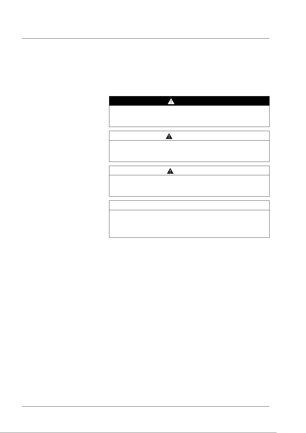
2.2.1 Signal behavior of function blocks with the input Enable
Example 1 Single execution without error (execution requires more than one call).
Enable
Error
Valid
Busy
Example 2 Single execution with error (execution requires more than one call).
Enable
Error
Valid
Busy
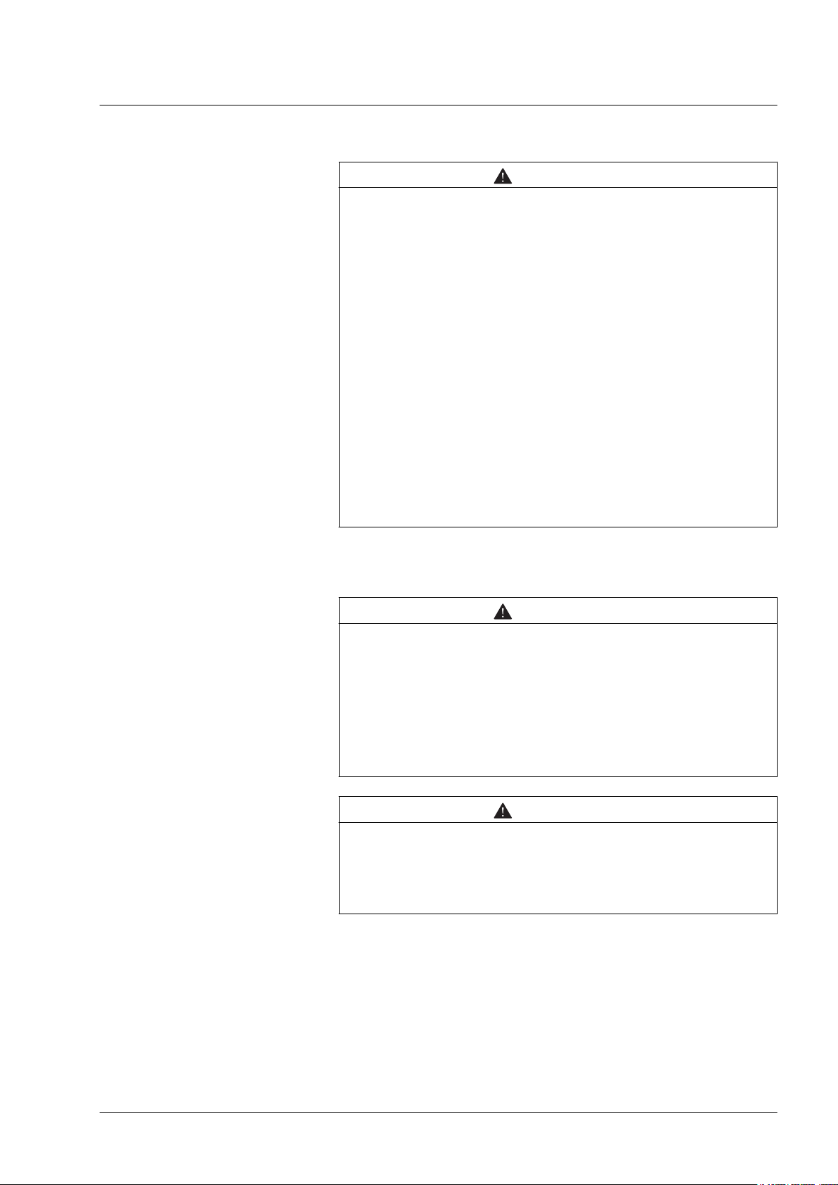
Example 3 Single execution without error (execution requires only one call).
Enable
Error
Valid
Busy
Example 4 Single execution with error (execution requires only one call).
Enable
Error
Valid
Busy
0198441113880, V2.08, 04.2011
Function blocks 19
Page 20
2 Altivar Library Guide
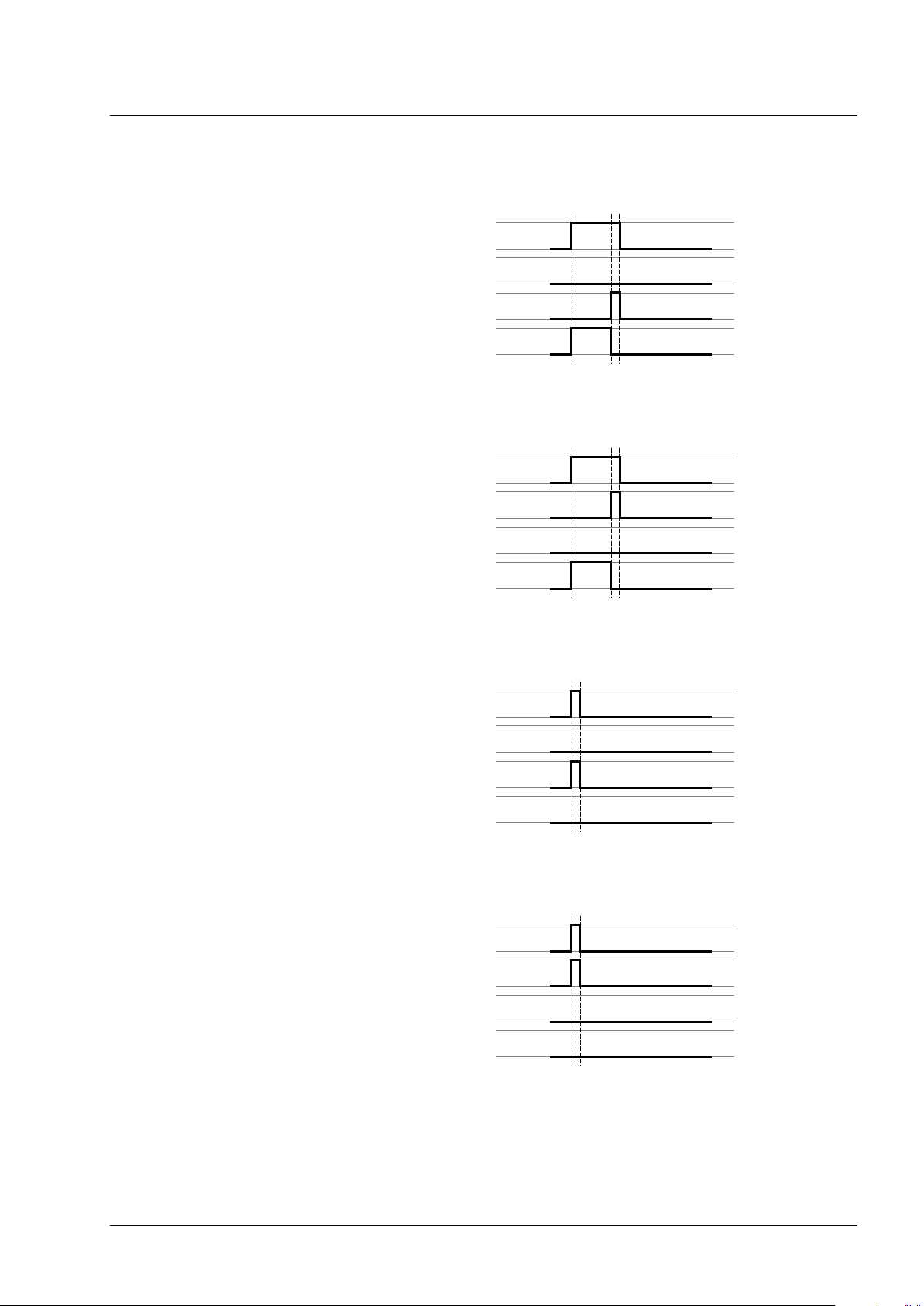
Example 5 Repeated execution without error (execution requires more than one
Example 6 Repeated execution with error (execution requires more than one
Altivar Library
call).
Enable
Error
Valid
Busy
call).
Enable
Error
Valid
Busy
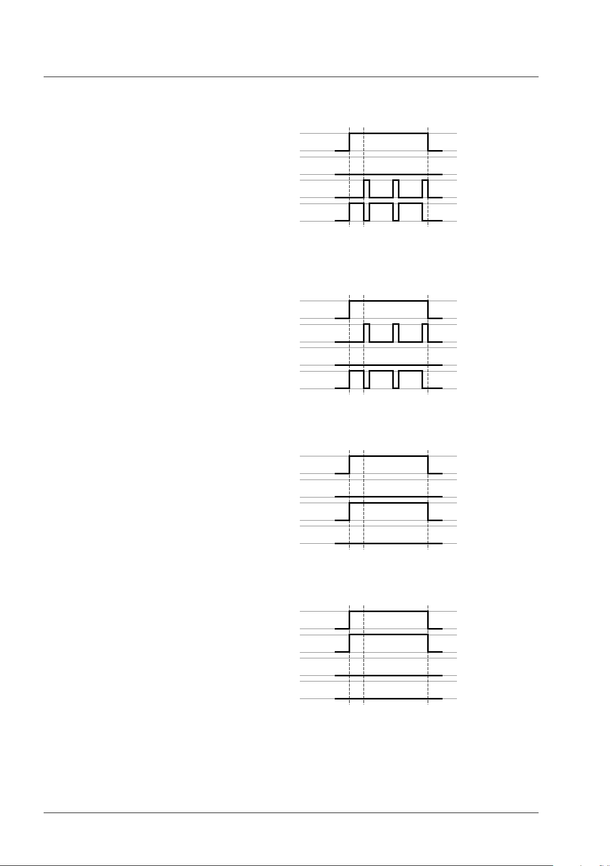
Example 7 Repeated execution without error (execution requires only one call).
Enable
Error
Valid
Busy
Example 8 Repeated execution with error (execution requires only one call).
Enable
Error
Valid
Busy
20 Function blocks
0198441113880, V2.08, 04.2011
Page 21
Altivar Library
2 Altivar Library Guide
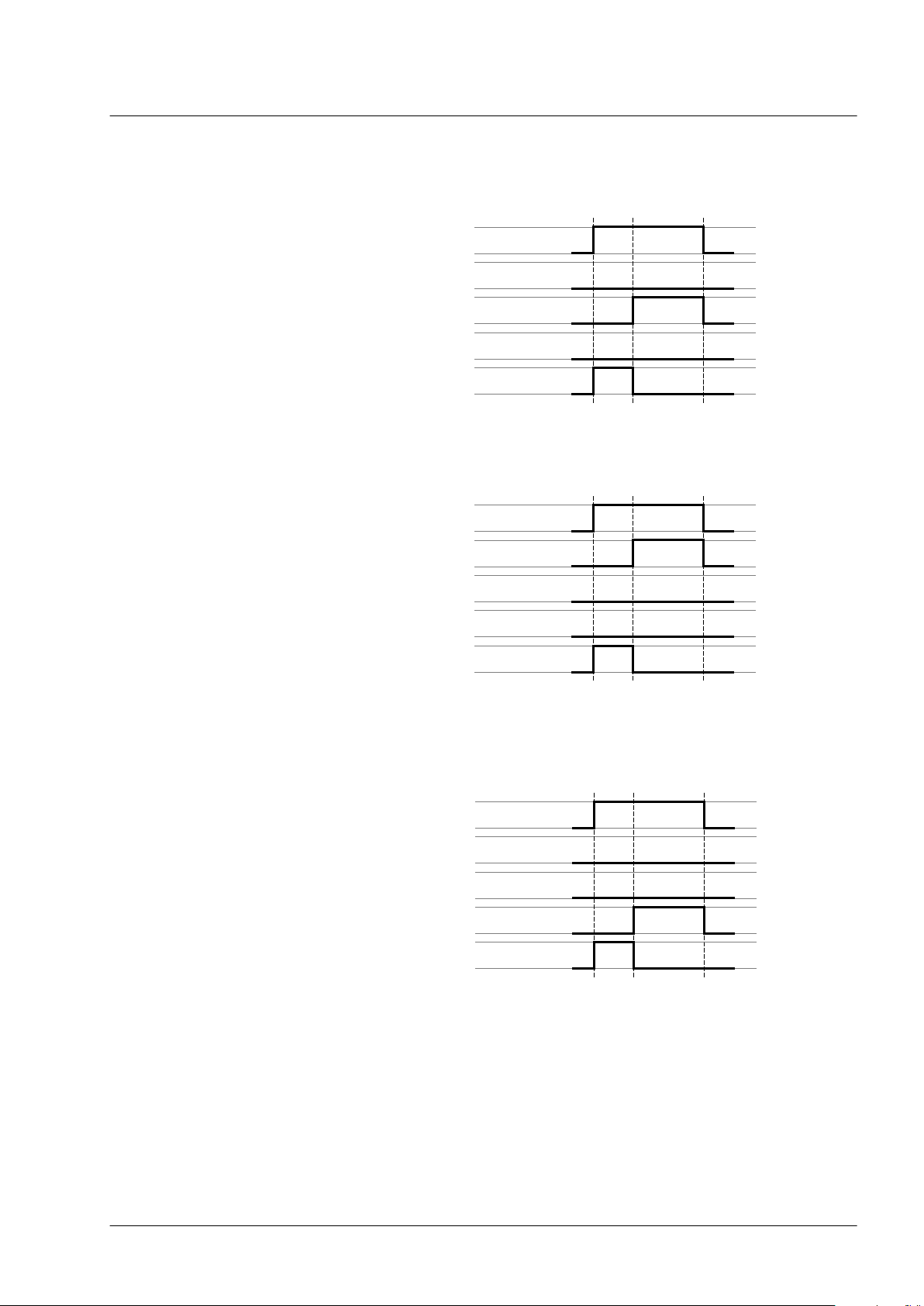
2.2.2 Signal behavior of function blocks with the input Execute
Example 1 Execution terminated without error.
Execute
Error
Done
CommandAborted
Busy
Example 2 Execution terminated with error.
Execute
Error
Done
CommandAborted
Busy
Example 3 Abortion of the execution because another function block takes over
control.
Execute
Error
Done
CommandAborted
Busy
0198441113880, V2.08, 04.2011
Function blocks 21
Page 22

2 Altivar Library Guide
Example 4 Execution completed without error after Execute has been set to
Altivar Library
FALSE during execution.
Execute
Error
Done
CommandAborted
Busy
22 Function blocks
0198441113880, V2.08, 04.2011
Page 23

MC_Power_ATV
Axis Axis_Ref_ATV
Enable BOOL
BOOL Status
BOOL Error
Altivar Library
2.3 Single axis
2.3.1 Initialization
2.3.1.1 MC_Power_ATV
Function description The function block enables or disables the power stage. TRUE at the
Graphical representation
2 Altivar Library Guide
The initialization function block enables or disables the power stage.
Other function blocks can only be used when the power stage is enabled.
input Enable enables the power stage. Once the power stage is enabled, the output Status is set. FALSE at the input Enable disables
the power stage. Once the power stage is disabled, the output Sta-
tus is reset. If errors occur during execution, the output Error is set.
Compatible devices ATV31/ATV312 and ATV71/ATV32
Inputs/outputs The table below shows the outputs.
Output Data type Description
Status BOOL
"2.2 Basic inputs and outputs"
Notes In the case of a Node Guarding error, the error memory must be reset
by means of the function block "2.4.5.2 MC_Reset_ATV" before the
power stage can be enabled again.
•
An asynchronous motor has no torque when it is at a standstill.
Enabling the power stage does not automatically generate torque.
•
If the input Enable = TRUE, one of the following errors is signaled if
the power supply is lost.
-
3120h (undervoltage)
-
ATV71/ATV32: FF34h (PowerOnTimeout_ATV)
-
If the 24V power supply is lost: 8100hh (NodeguardError_ATV)
-
The output Status is set to FALSE and the output Error to
TRUE. Once the power supply is available again, the output
Status is set back to TRUE.
Value range: FALSE, TRUE
Initial value: FALSE
FALSE: Power stage is disabled.
TRUE: Power stage is enabled.
0198441113880, V2.08, 04.2011
Function blocks 23
Page 24

MC_Jog_ATV
Axis Axis_Ref_ATV
Forward BOOL
Backward BOOL
Velocity INT
BOOL Done
BOOL Busy
BOOL CommandAborted
BOOL Error
2 Altivar Library Guide
2.3.2 Operating mode Jog
2.3.2.1 MC_Jog_ATV
Function description The function block starts the operating mode Jog. TRUE at the input
Graphical representation
Altivar Library
In the operating mode Jog, a movement is made from the actual motor
position in the desired direction. The velocity can be set. As long as
the signal for the direction is available, a continuous movement is
made in the desired direction.
If movements in positive and negative directions are requested at the
same time, there is no motor movement.
Forward or the input Backward starts the jog movement. If both the
inputs Forward and Backward are FALSE, the operating mode is
terminated and the output Done is set. If both the inputs Forward and
Backward are TRUE, the operating mode remains active, the jog
movement is stopped and the output Busy remains set.
Compatible devices ATV31/ATV312 and ATV71/ATV32
24 Function blocks
0198441113880, V2.08, 04.2011
Page 25

Altivar Library
Inputs/outputs The table below shows the inputs.
Input Data type Description
Forward BOOL
Backward
Velocity
BOOL
INT
Value range: FALSE, TRUE
Initial value: FALSE
Forward = FALSE and Backward = FALSE:
Movement is terminated.
Forward = TRUE and Backward = FALSE:
Movement in positive direction is started if Velocity >0.
Movement in negative direction is started if Velocity <0.
Forward = FALSE and Backward = TRUE:
Movement in negative direction is started if Velocity >0.
The movement is stopped if Velocity <0.
Forward = TRUE and Backward = TRUE:
The movement in the current direction continues. If the inputs
Forward or Backward are set to FALSE, the movement is
continued in the direction and at the velocity valid at that point
in time.
Value range: -5000 ... +5000
Initial value: 0
Target velocity for the operating mode. Adjustable in increments of 0.1 Hz.
NOTE:
The values for LowFrequency and HighFrequency are set
in the function block SetFrequencyRange_ATV.
If the value for the target velocity velocity is less than the
value for LowFrequency, the movement is made with the
velocity value for LowFrequency. No error is signaled.
If the value for the target velocity velocity is greater than the
value for HighFrequency, the movement is made with the
velocity value for HighFrequency. No error is signaled.
2 Altivar Library Guide
"2.2 Basic inputs and outputs"
0198441113880, V2.08, 04.2011
Function blocks 25
Page 26

VelocityControlAnalogInput_ATV
Axis Axis_Ref_ATV
Execute BOOL
NegativeDir BOOL
BOOL InVelocity
BOOL Busy
BOOL CommandAborted
BOOL Error
2 Altivar Library Guide
2.3.3 Operating mode Speed Control
In the operating mode Speed Control, you can set a reference velocity
via an analog input.
2.3.3.1 VelocityControlAnalogInput_ATV
Function description The function block uses the reference values supplied by the analog
input selected with the function block
"2.3.3.2 VelocityControlSelectAI_ATV".
Graphical representation
Compatible devices ATV31/ATV312 and ATV71/ATV32
Inputs/outputs The table below shows the inputs.
Altivar Library
Input Data type Description
NegativeDir BOOL
Value range: FALSE, TRUE
Initial value: FALSE
FALSE: Clockwise rotation.
TRUE: Counter-clockwise rotation.
The table below shows the outputs.
Output Data type Description
InVelocity BOOL
Value range: FALSE, TRUE
Initial value: FALSE
FALSE: The velocity does not correspond to the reference
value.
FALSE: The velocity corresponds to the reference value.
"2.2 Basic inputs and outputs"
Notes See also "2.4.2.3 SetFrequencyRange_ATV" and
"2.3.3.2 VelocityControlSelectAI_ATV".
If voltage levels -10V ... 10V are used, the direction of movement
(rotation) is inversed when the sign changes. If the voltage is 0 V, this
may result in jumps in the direction of movement, in the minimum frequency and in jumps at standstill.
NOTE for ATV31: If you have selected the analog current input
(0 mA ... 20 mA), the following frequency levels are used:
•
The minimum frequency is used below 4 mA.
•
The medium frequency is used at 12 mA.
•
The maximum frequency is used at 20 mA.
26 Function blocks
0198441113880, V2.08, 04.2011
Page 27

VelocityControlSelectAI_ATV
Axis Axis_Ref_ATV
Execute BOOL
InputNumber INT
BOOL Done
BOOL Busy
BOOL Error
Altivar Library
2.3.3.2 VelocityControlSelectAI_ATV
Function description This function block is used to select the analog input for supplying the
reference value. See also "2.3.3.1 VelocityControlAnalogInput_ATV".
Graphical representation
Compatible devices ATV31/ATV312 and ATV71/ATV32
Inputs/outputs The table below shows the inputs.
Input Data type Description
InputNumber INT
Value range: 1 ... 16
Initial value: 1
1: AI1
2: AI2
3: AI3 (ATV71 only with expansion card)
4: AI4 (ATV71 only and only with expansion card)
16: AIP (internal potentiometer, ATV31/312 only)
2 Altivar Library Guide
"2.2 Basic inputs and outputs"
Notes The function block can only be executed if the drive is in the operating
state 3 Switch On Disabled (operating state of drive). To transition to
this state, disable the power stage with the function block
"2.3.1.1 MC_Power_ATV".
0198441113880, V2.08, 04.2011
Function blocks 27
Page 28

MC_MoveVelocity_ATV
Axis Axis_Ref_ATV
Execute BOOL
Velocity INT
BOOL InVelocity
BOOL Busy
BOOL CommandAborted
BOOL Error
2 Altivar Library Guide
2.3.4 Operating mode Profile Velocity
You can set a target velocity in the operating mode Profile Velocity.
The movement is performed with this target velocity in the operating
mode Profile Velocity. The movement continues until a new target
velocity is set or until the operating mode is aborted.
Transitions between two target velocities are performed on the basis
of a motion profile. The motion profile is determined by the profile generator in the drive on the basis of the actual velocity, the target velocity and the acceleration and deceleration ramps.
2.3.4.1 MC_MoveVelocity_ATV
Function description The function block starts the operating mode Profile Velocity with the
velocity Velocity. When the target velocity is reached, InVelocity
is set.
Graphical representation
Altivar Library
Compatible devices ATV31/ATV312 and ATV71/ATV32
Inputs/outputs The table below shows the inputs.
Input Data type Description
Velocity INT
Value range: -5000 ... +5000
Initial value: 0
Target velocity in [0.1Hz]
NOTE:
The values for LowFrequency and HighFrequency are set
in the function block SetFrequencyRange_ATV.
If the value for the target velocity velocity is less than the
value for LowFrequency, the movement is made with the
velocity value for LowFrequency. No error is signaled.
If the value for the target velocity velocity is greater than the
value for HighFrequency, the movement is made with the
velocity value for HighFrequency. No error is signaled.
The table below shows the outputs.
Output Data type Description
InVelocity BOOL
Value range: FALSE, TRUE
Initial value: FALSE
FALSE: Target velocity not yet reached.
TRUE: Target velocity reached.
"2.2 Basic inputs and outputs"
Notes In the operating mode Profile Velocity, a position overtravel does not
trigger an error. A position overtravel results in a loss of the zero point.
28 Function blocks
0198441113880, V2.08, 04.2011
Page 29

MC_Stop_ATV
Axis Axis_Ref_ATV
Execute BOOL
BOOL Done
BOOL Busy
BOOL Error
Altivar Library
2.3.5 Stopping
2.3.5.1 MC_Stop_ATV
Function description The function block is used to stop the current movement. The operat-
Graphical representation
Compatible devices ATV31/ATV312 and ATV71/ATV32
Inputs/outputs "2.2 Basic inputs and outputs"
2 Altivar Library Guide
Each operating mode can be canceled by stopping. Stopping the
operating mode does not generate an error.
ing mode is stopped by the function block.
Notes
The type of deceleration (deceleration ramp, coasting down without
braking) is set via the parameter Stt. Note the pertinent information in
the product manual.
•
The deceleration ramp is set with the function block
"2.4.2.2 SetDriveRamp_ATV".
•
The function block can only be interrupted by disabling the power
stage via the function block "2.3.1.1 MC_Power_ATV".
•
As long as the input Execute is TRUE, no other function block
with the exception of "2.3.1.1 MC_Power_ATV" can be started.
0198441113880, V2.08, 04.2011
Function blocks 29
Page 30

MC_ReadActualVelocity_ATV
Axis Axis_Ref_ATV
Enable BOOL
BOOL Valid
BOOL Busy
BOOL Error
INT Velocity
2 Altivar Library Guide
2.4 Administrative
2.4.1 Reading a parameter
The following functions blocks allow you to read drive parameters
such as the actual position or the actual velocity.
An additional function block provides read access to individual parameters of the device. See the product manual for a description of the
parameters.
2.4.1.1 MC_ReadActualVelocity_ATV
Function description The function block is used to read the actual velocity of the motor.
Graphical representation
Altivar Library
Compatible devices ATV31/ATV312 and ATV71/ATV32
Inputs/outputs The table below shows the outputs.
Output Data type Description
Velocity INT
Value range: -5000 ... +5000
Initial value:
Actual velocity in min
"2.2 Basic inputs and outputs"
Notes The function block uses Service Data Objects (SDO) to read the
parameter from the device. Therefore, it is strongly recommended not
to permanently set the input Enable to TRUE. This may cause overload on the fieldbus. It is recommended to deactivate the function
block when the output Busy is set to FALSE.
The value is specified in min-1. Example: At a frequency of 3 Hz and 2
pairs of poles, this results in a velocity of 90 min-1. (3 Hz * 60 s / 2
pairs of poles = 90 min-1). Note that the reference value for the velocity
("2.3.4.1 MC_MoveVelocity_ATV") is specified in increments of 0.1 Hz
(3 Hz -> Velocity = 30).
-1
30 Function blocks
0198441113880, V2.08, 04.2011
Page 31

MC_ReadActualTorque_ATV
Axis Axis_Ref_ATV
Enable BOOL
BOOL Valid
BOOL Busy
BOOL Error
INT Torque
Altivar Library
2.4.1.2 MC_ReadActualTorque_ATV
Function description The function block is used to read the actual torque of the motor.
Graphical representation
Compatible devices ATV31/ATV312 and ATV71/ATV32
Inputs/outputs The table below shows the outputs.
Output Data type Description
Torque INT
"2.2 Basic inputs and outputs"
Value range: -3276.7 ... 3276.7
Initial value:
Actual torque of the motor on increments of 0.1 %.
2 Altivar Library Guide
Notes The function block uses Service Data Objects (SDO) to read the
parameter. Therefore, it is strongly recommended not to permanently
set the input Enable to TRUE. This may cause overload on the fieldbus. It is recommended to deactivate the function block when the output Busy is set to FALSE.
0198441113880, V2.08, 04.2011
Function blocks 31
Page 32

MC_ReadStatus_ATV
Axis Axis_Ref_ATV
Enable BOOL
BOOL Valid
BOOL Busy
BOOL Error
BOOL Errorstop
BOOL Disabled
BOOL Stopping
BOOL StandStill
BOOL DiscreteMotion
BOOL ContinuousMotion
BOOL ConstantVelocity
BOOL Accelerating
BOOL Decelerating
2 Altivar Library Guide
2.4.1.3 MC_ReadStatus_ATV
Function description The function block is used to read the current status of the device.
Graphical representation
Compatible devices ATV31/ATV312 and ATV71/ATV32
Altivar Library
32 Function blocks
0198441113880, V2.08, 04.2011
Page 33

Altivar Library
Inputs/outputs The table below shows the outputs.
Output Data type Description
ErrorStop BOOL
Disabled BOOL
Stopping
StandStill
DiscreteMotion BOOL
ContinuousMotion BOOL
ConstantVelocity BOOL
Accelerating BOOL
Decelerating BOOL
BOOL
BOOL
Value range: FALSE, TRUE
Initial value: FALSE
TRUE: The movement has been interrupted by an error.
Value range: FALSE, TRUE
Initial value: FALSE
FALSE: Power stage is enabled.
TRUE: Power stage is disabled
Value range: FALSE, TRUE
Initial value: FALSE
TRUE: The function block "2.3.5.1 MC_Stop_ATV" is being
executed or the movement is being stopped.
Value range: FALSE, TRUE
Initial value: FALSE
TRUE: The movement hast been stopped.
Value range: FALSE, TRUE
Initial value: FALSE
TRUE: The operating mode Profile Position has been started.
Value range: FALSE, TRUE
Initial value: FALSE
TRUE: The operating mode Profile Velocity has been started.
Value range: FALSE, TRUE
Initial value: FALSE
TRUE: A movement at a constant velocity is performed.
Value range: FALSE, TRUE
Initial value: FALSE
TRUE: The motor accelerates.
Value range: FALSE, TRUE
Initial value: FALSE
TRUE: The motor decelerates.
2 Altivar Library Guide
"2.2 Basic inputs and outputs"
Notes At any given point in time, the drive is in one of the states: StandStill,
DiscreteMotion, ContinuousMotion, Stopping, Disabled or ErrorStop.
The corresponding output is then TRUE.
0198441113880, V2.08, 04.2011
Function blocks 33
Page 34

MC_ReadParameter_ATV
Axis Axis_Ref_ATV
Enable BOOL
ParameterNumber INT
Index UINT
Subindex UINT
BOOL Valid
BOOL Busy
BOOL Error
DINT Value
UINT Length
2 Altivar Library Guide
2.4.1.4 MC_ReadParameter_ATV
Function description The function block reads an object from the device parameter list.
Graphical representation
Compatible devices ATV31/ATV312 and ATV71/ATV32
Inputs/outputs The table below shows the inputs.
Input Data type Description
ParameterNumber INT
Index
Subindex
UINT
UINT
Value range: 0 ... 65535
Initial value: 1000
Number of the parameter:
10: Actual velocity.
11: Target velocity.
1000: Selection via index and subindex.
Value range: 0 ... 65535
Initial value:
Index of parameter to be read. Only valid if ParameterNum-
ber = 1000.
See the product manual for an overview of the parameters.
Value range: 0 ... 255
Initial value:
Subindex of parameter to be read. Only valid if Parameter-
Number = 1000.
See the product manual for an overview of the parameters.
Altivar Library
The table below shows the outputs.
Output Data type Description
Value DINT
Length UINT
Value range: -2147483648 ... 2147483647
Initial value: 0
Value of the parameter.
Value range: 1 ... 4
Initial value: 4
Length of the parameter in bytes.
"2.2 Basic inputs and outputs"
Notes The function block uses Service Data Objects (SDO) to read the
parameter. Therefore, it is strongly recommended not to permanently
set the input Enable to TRUE. This may cause overload on the fieldbus. It is recommended to deactivate the function block when the
input Busy is set to FALSE.
34 Function blocks
0198441113880, V2.08, 04.2011
Page 35

GetSupplierVersion
WORD GetSupplierVersion
Altivar Library
2.4.1.5 GetSupplierVersion
Function description The function block returns the version of the library of the device.
Graphical representation
Compatible devices ATV31/ATV312 and ATV71/ATV32
Inputs/outputs The table below shows the outputs.
Output Data type Description
GetSupplierVersion
WORD
The output provides the version number of the library. Convert
the decimal value to hex.
Example: GetSupplierVersion = 12368 = 3050h = Version
3.0.5.0
2 Altivar Library Guide
0198441113880, V2.08, 04.2011
Function blocks 35
Page 36

MC_WriteParameter_ATV
Axis Axis_Ref_ATV
Execute BOOL
ParameterNumber INT
Value DINT
Index UINT
Subindex UINT
Length UINT
BOOL Done
BOOL Busy
BOOL Error
2 Altivar Library Guide
2.4.2 Writing a parameter
2.4.2.1 MC_WriteParameter_ATV
Function description The function block is used to write a value to a specific parameter.
Graphical representation
Altivar Library
The following function bocks allow you to write drive parameters, for
example the values for the acceleration and deceleration ramps.
An additional function block provides write access to individual parameters of the device. See the product manual for a description of the
parameters.
Compatible devices ATV31/ATV312 and ATV71/ATV32
Inputs/outputs The table below shows the inputs.
Input Data type Description
ParameterNumber INT
Value DINT
Index UINT
Subindex
Length
UINT
UINT
Value range: 1000
Initial value: 1000
Reserved.
Value range: -2147483648 ... 2147483647
Initial value: 0
New value to be written to the parameter.
Value range: 0 ... 65535
Initial value: 0
Index of the parameter to be written.
See the product manual for a list of the parameters with the
corresponding CANopen address.
Value range: 0 ... 255
Initial value: 0
Subindex of the parameter to be written.
See the product manual for a list of the parameters with the
corresponding CANopen address.
Value range: 0 ... 4
Initial value: 0
Length of the parameter to be written in bytes.
"2.2 Basic inputs and outputs"
Notes If the inputs ParameterNumber, Index or Subindex are changed
36 Function blocks
while Busy is TRUE, the function block uses the previous values. The
next time the function block is executed, the new values will be used.
0198441113880, V2.08, 04.2011
Page 37

SetDriveRamp_ATV
Axis Axis_Ref_ATV
Execute BOOL
Acceleration DINT
Deceleration DINT
BOOL Done
BOOL Busy
BOOL Error
Altivar Library
2.4.2.2 SetDriveRamp_ATV
Function description The function block configures the acceleration ramp and the decelera-
tion ramp of the device.
Graphical representation
Compatible devices ATV31/ATV312 and ATV71/ATV32
Inputs/outputs The table below shows the inputs.
Input Data type Description
Acceleration DINT
Deceleration
DINT
Value range: 1 ... 9999
Initial value: 30
Time for the acceleration ramp in 0.1 s.
Example: With a value of 30, 3 seconds are required to accelerate from 0 to the nominal frequency of the motor. It must be
possible to reach the value with the available nominal torque of
the motor.
Value range: 1 ... 9999
Initial value: 30
Time for the deceleration ramp in 0.1 s.
Example: With a value of 30, 3 seconds are required to decelerate from 0 to the nominal frequency of the motor. It must be
possible to reach the value with the available nominal torque of
the motor.
2 Altivar Library Guide
0198441113880, V2.08, 04.2011
Function blocks 37
"2.2 Basic inputs and outputs"
Notes Note the following for drives with high external moments of inertia or
for highly dynamic applications: The motors regenerate energy during
deceleration. The DC bus can absorb a limited amount of energy in
the capacitors. Connecting additional capacitors to the DC bus increases the amount of energy that can be absorbed. If the capacity of the
capacitors is exceeded, the excess energy must be discharged via
internal or external braking resistors. If the energy is not discharged,
an overvoltage monitor will shut off the power stage. Overvoltages can
be limited by adding a braking resistor with a corresponding braking
resistor controller. This converts the regenerated energy to heat
energy during deceleration.
Page 38

SetFrequencyRange_ATV
Axis Axis_Ref_ATV
Execute BOOL
LowFrequency DINT
HighFrequency DINT
MaxFrequency DINT
BOOL Done
BOOL Busy
BOOL Error
2 Altivar Library Guide
2.4.2.3 SetFrequencyRange_ATV
Function description The function block is used to configure the frequency ranges of the
Graphical representation
Compatible devices ATV31/ATV312 and ATV71/ATV32
Inputs/outputs The table below shows the inputs.
Altivar Library
device for the function blocks MC_MoveVelocity and MC_Jog. If the
frequency (speed of rotation) falls below the value in LowFrequency,
the device uses the frequency specified in LowFrequency without
triggering an error message. If the frequency (speed of rotation)
exceeds the value in HighFrequency, the device uses the frequency
specified in HighFrequency without triggering an error message.
Input Data type Description
LowFrequency DINT
HighFrequency DINT
MaxFrequency DINT
Value range: 0 ... HighFrequency
Initial value: 0
Motor frequency at minimum reference value.
Value range: LowFrequency ... MaxFrequency
Initial value: 500
Motor frequency at maximum reference value.
Value range: 100 ... 5000/10000 (see product manual)
Initial value: 600
Maximum permissible motor frequency
Adapt the value to the motor and the mechanical situation. The
maximum frequency depends on certain parameters. Note the
pertinent information in the product manual.
"2.2 Basic inputs and outputs"
38 Function blocks
0198441113880, V2.08, 04.2011
Page 39

ResetParameters_ATV
Axis Axis_Ref_ATV
Execute BOOL
BOOL Done
BOOL Busy
BOOL Error
Altivar Library
2.4.2.4 ResetParameters_ATV
Function description This function block restores all parameters to the factory settings.
Graphical representation
Compatible devices ATV31/ATV312 and ATV71/ATV32
Inputs/outputs "2.2 Basic inputs and outputs"
Notes Observe the information provided in chapter "Preparing the drive".
2 Altivar Library Guide
•
The new settings are not saved to the EEPROM. Use
"2.4.2.5 StoreParameters_ATV" to save the new settings to the
EEPROM.
0198441113880, V2.08, 04.2011
Function blocks 39
Page 40

StoreParameters_ATV
Axis Axis_Ref_ATV
Execute BOOL
BOOL Done
BOOL Busy
BOOL Error
2 Altivar Library Guide
2.4.2.5 StoreParameters_ATV
Function description The function block saves the parameter values to the EEPROM.
Graphical representation
Compatible devices ATV31/ATV312 and ATV71/ATV32
Inputs/outputs "2.2 Basic inputs and outputs"
Altivar Library
40 Function blocks
0198441113880, V2.08, 04.2011
Page 41

UploadDriveParameter_ATV
Axis Axis_Ref_ATV
ParameterSetVar TypeParameterSetVar_ATV
Execute BOOL
BOOL Done
BOOL Busy
BOOL Error
UINT Size
Altivar Library
2.4.3 Saving and restoring device configuration
Using a function block, you can upload the device configuration from
the drive to the controller. A further function block lets you download a
device configuration stored on the controller to a drive.
2.4.3.1 UploadDriveParameter_ATV
Function description The function blocks reads the parameter values that can be modified
from the device. See also "2.4.3.2 DownloadDriveParameter_ATV".
Graphical representation
Compatible devices ATV31/ATV312 and ATV71/ATV32
Inputs/outputs The table below shows the inputs/outputs.
2 Altivar Library Guide
Input/output Data type Description
ParameterSetVar TypeParameterSetVar_ATV
Value range:
Initial value:
List of the device parameters. Predefined data structure (array
of DINT).
The table below shows the outputs.
Output Data type Description
Size UINT
Value range:
Initial value: 0
Number of parameters read. In the case of an incorrect upload,
the value remains 0.
"2.2 Basic inputs and outputs"
Notes
•
The two function blocks "2.4.3.2 DownloadDriveParameter_ATV"
and "2.4.3.1 UploadDriveParameter_ATV" allow you to save the
parameters stored in a device to an identical device without using
the commissioning software.
0198441113880, V2.08, 04.2011
Function blocks 41
Page 42

DownloadDriveParameter_ATV
Axis Axis_Ref_ATV
ParameterSetVar TypeParameterSetVar_ATV
Execute BOOL
BOOL Done
BOOL Busy
BOOL Error
UINT Index
UINT Subindex
2 Altivar Library Guide
2.4.3.2 DownloadDriveParameter_ATV
Function description The function blocks writes the parameter values that can be modified
to the device. Before calling the function block, you must execute
"2.4.3.1 UploadDriveParameter_ATV". If not, an error message will be
generated.
Graphical representation
Compatible devices ATV31/ATV312 and ATV71/ATV32
Inputs/outputs The table below shows the inputs/outputs.
Input/output Data type Description
ParameterSetVar TypeParameterSetVar_ATV
Value range:
Initial value:
List of device parameters
Altivar Library
The table below shows the outputs.
Output Data type Description
Index UINT
Subindex
UINT
Value range: 0 ... 65535
Initial value:
Index of the parameter. See the product manual for an overview of the parameters.
Value range: 0 ... 255
Initial value:
Subindex of the parameter. See the product manual for an
overview of the parameters.
"2.2 Basic inputs and outputs"
Notes
•
The function block can only be executed if the drive is in the operating state 3 Switch On Disabled (operating state of drive). To transition to this state, disable the power stage with the function block
"2.3.1.1 MC_Power_ATV".
•
In order to permanently store the parameters, you must save them
to the EEPROM using the function block
"2.4.2.5 StoreParameters_ATV".
•
The two function blocks "2.4.3.2 DownloadDriveParameter_ATV"
and "2.4.3.1 UploadDriveParameter_ATV" allow you to save the
parameters stored in a device to an identical device without using
the commissioning software.
42 Function blocks
0198441113880, V2.08, 04.2011
Page 43

ReadAnalogInput_ATV
Input Input_Ref_ATV
Enable BOOL
InputNumber INT
BOOL Valid
BOOL Busy
BOOL Error
INT Value
Altivar Library
2.4.4 Inputs and outputs
The following function blocks allow you to access the digital and analog inputs and outputs of all CAN nodes in the system..
2.4.4.1 ReadAnalogInput_ATV
Function description The function block reads the current value of an analog input.
Graphical representation
Compatible devices ATV31/ATV312 and ATV71/ATV32
Inputs/outputs The table below shows the inputs.
Input Data type Description
InputNumber INT
Value range: 1 ... 4
Initial value: 1
1: AI1
2: AI2
3: AI3 (ATV71 only with expansion card)
4: AI4 (ATV71 only and only with expansion card)
2 Altivar Library Guide
The table below shows the outputs.
Output Data type Description
Value INT
Value range: Initial value: 0
Corresponds to the input voltage in mV or the input current in
0.001 mA increments at the selected analog input.
"2.2 Basic inputs and outputs"
Notes
•
The analog inputs of ATV31/ATV312 and ATV71/ATV32 are different. See the product manual for additional information.
0198441113880, V2.08, 04.2011
Function blocks
43
Page 44

MC_ReadDigitalInput_ATV
Input Input_Ref_ATV
Enable BOOL
InputNumber INT
BOOL Valid
BOOL Busy
BOOL Error
BOOL Value
WORD Inputs
2 Altivar Library Guide
2.4.4.2 MC_ReadDigitalInput_ATV
Function description Reads the current state of the digital inputs of the drive.
Graphical representation
Compatible devices ATV31/ATV312 and ATV71/ATV32
Altivar Library
44
0198441113880, V2.08, 04.2011
Function blocks
Page 45

Altivar Library
Inputs/outputs The table below shows the inputs.
Input Data type Description
InputNumber INT
Value range: 1 ... 14 (product-dependent)
Initial value: 1
Number of the input to be read.
Assignment of the inputs of the drive.
1: IL1
2: IL2
3: IL3
4: IL4
5: IL5
6: IL6
Inputs of the I/O expansion card (ATV71):
7: IL7
8: IL8
9: IL9
10: IL10
Inputs of the I/O expansion card (ATV71):
11: IL11
12: IL12
13: IL13
14: IL14
15: Reserved. Value = 0.
2 Altivar Library Guide
The table below shows the outputs.
Output Data type Description
Value BOOL
Inputs
WORD
Value range: FALSE, TRUE
Initial value: FALSE
FALSE: Level at selected input is 0 V.
TRUE: Level at selected input is 24 V.
Value range: 0000h ... 3FFFh
Initial value: 0000
Image of the inputs as a bit pattern.
Bit 0: IL1
Bit 1: IL2
Bit 2: IL3
Bit 3: IL4
Bit 4: IL5
Bit 5: IL6
Inputs of the I/O expansion card (ATV71):
Bit 6: IL7
Bit 7: IL8
Bit 8: IL9
Bit 9: IL10
Inputs of the I/O expansion:
Bit 10: IL11:
Bit 11: IL12
Bit 12: IL13
Bit 13: IL14
Bit 14 and bit 15: Reserved. Value = 0.
h
0198441113880, V2.08, 04.2011
Function blocks
"2.2 Basic inputs and outputs"
Notes See the product manual for a description of the digital inputs.
45
Page 46

MC_ReadDigitalOutput_ATV
Output Output_Ref_ATV
Enable BOOL
OutputNumber INT
BOOL Valid
BOOL Busy
BOOL Error
BOOL Value
WORD Outputs
2 Altivar Library Guide
2.4.4.3 MC_ReadDigitalOutput_ATV
Function description The function block is used to get the current state of the digital out-
puts.
Graphical representation
Compatible devices ATV31/ATV312 and ATV71/ATV32
Altivar Library
46
0198441113880, V2.08, 04.2011
Function blocks
Page 47

Altivar Library
Inputs/outputs The table below shows the inputs.
Input Data type Description
OutputNumber INT
The table below shows the outputs.
Output Data type Description
Value BOOL
Outputs
WORD
Value range: 1 ... 8 (product-dependent)
Initial value: 1
Number of the output to be read.
ATV31/312/32:
1: Relay1
2: Relay2
3: LO
ATV71:
1: Relay1
2: Relay2
3: Relay3
4: Relay4
5: LO1
6: LO2
7: LO3
8: LO4
Value range: FALSE, TRUE
Initial value: FALSE
FALSE: Level at selected output is 0 V.
TRUE: Level at selected output is 24 V.
Value range: 00h ...0Fh
Initial value: 00
Image of the outputs as a bit pattern.
ATV31/312/32:
Bit 0: Relay1
Bit 1: Relay2
Bit 2: LO
ATV71:
Bit 0: Relay1
Bit 1: Relay2
Bit 2: Relay3
Bit 3: Relay4
Bit 4: LO1
Bit 5: LO2
Bit 6: LO3
Bit 7: LO4
The value of the other bits is 0.
2 Altivar Library Guide
h
0198441113880, V2.08, 04.2011
Function blocks
"2.2 Basic inputs and outputs"
Notes See the product manual for a description of the digital outputs.
47
Page 48

MC_WriteDigitalOutput_ATV
Output Output_Ref_ATV
Execute BOOL
OutputNumber INT
Value BOOL
AllOutputs BOOL
Outputs WORD
BOOL Done
BOOL Busy
BOOL Error
2 Altivar Library Guide
2.4.4.4 MC_WriteDigitalOutput_ATV
Function description The function blocks writes values to the digital outputs.
Graphical representation
Compatible devices ATV31/ATV312 and ATV71/ATV32
Inputs/outputs The table below shows the inputs.
Input Data type Description
OutputNumber INT
Value
AllOutputs
Outputs
BOOL
BOOL
WORD
Signal output to which to write.
ATV31/312/32:
1: Relay1
2: Relay2
3: LO
ATV71:
1: Relay1
2: Relay2
3: Relay3
4: Relay4
5: LO1
6: LO2
7: LO3
8: LO4.
Value range: FALSE, TRUE
Initial value: FALSE
FALSE: 0V is written to the selected signal output.
TRUE: 24V is written to the selected signal output.
Value range: FALSE, TRUE
Initial value:
FALSE: The signal output to be written to is set via input Out-
putNumber.
TRUE: The signal outputs to be written to are set via input
Output.
Value range: 0000h ... 0003h
Initial value: 0
The input defines the signal outputs to which the value defined
in Value is to be written.
0000 0000 0000 00002 (0000h) = Signal output/relay 1
0000 0000 0000 00102 (0002h) = Signal output/relay 2
0000 0000 0000 00112 (0003h) = Signal output/relay 1 and signal output/relay 2
Altivar Library
48
"2.2 Basic inputs and outputs"
0198441113880, V2.08, 04.2011
Function blocks
Page 49

MC_ReadAxisError_ATV
Axis Axis_Ref_ATV
Enable BOOL
BOOL Valid
BOOL Busy
BOOL Error
WORD ErrorID
Altivar Library
2.4.5 Error handling
2.4.5.1 MC_ReadAxisError_ATV
Function description The function block reads the error information pertaining to the most
Graphical representation
2 Altivar Library Guide
For error handling, each function block has an output Error which is
set if a synchronous or asynchronous error occurs.
The function block MC_ReadAxisError_xxx is called to analyze the
cause of the error. The function block contains the stored error information.
The function block MC_Reset_xxx deletes the error information
entered. Future error information can now be stored.
If an additional error occurs, the error information is only stored if no
stored error information already exists. If there is still information pertaining to a previous error, the new error message is ignored.
recent error.
Compatible devices ATV31/ATV312 and ATV71/ATV32
Inputs/outputs The table below shows the outputs.
Output Data type Description
ErrorID WORD
Value range: 0000h ... FFFFh
Initial value: 0000
0: No error stored.
>0: Stored error number.
See the product manual for an overview of the error numbers.
"2.2 Basic inputs and outputs"
h
0198441113880, V2.08, 04.2011
Function blocks
49
Page 50

2 Altivar Library Guide
Table of error numbers The table below shows the error numbers of the library. See the prod-
Altivar Library
uct manual for the error numbers of the drive.
ErrorID hexadecimal
1000
h
2310
h
2320
h
2330
h
2340
h
3110
h
3120
h
3130
h
3310
h
4210
h
5520
h
6100
h
6300
h
7300
h
7510
h
8100
h
9000
h
A309
h
FE00
h
FE01
h
FF00
h
FF01
h
FF02
h
FF03
h
FF04
h
FF05
h
FF06
h
FF07
h
FF08
h
FF09
h
FF0A
h
FF0B
h
FF0C
h
FF0D
h
FF0E
h
FF0F
h
FF10
h
ErrorID decimal HMI Description
4096
8976
8992
CrF
OLF
SOF
OCF
SCF
Capacitor error
Motor overload
Speed of rotation too high
Motor overcurrent
Motor short circuit
9008 SCF Short circuit motor phases (ground fault)
9024 SCF Short circuit motor phase (phase to phase)
12560
12576
12592
13072
16912
21792
24832
25344
29440
29968
33024
OSF
USF
PHF
ObF
OPF
OHF
EEF
InF
CCF
LFF
SLF
COF
Overvoltage mains supply
Undervoltage mains supply
Error mains phases
DC bus overvoltage
Error motor phase
Overtemperature
EEPROM error
Internal event
Parameter out of permissible range
Error at AI3
Modbus communication error
CANopen communication error, Heartbeat or Life
Guard error
36864
41737
65024
65025
EPF
tnF
bLF
External error
Drive not in operating state6 Operation Enabled
Error during autotuning
Error brake controller
65280 - Toggle bit unchanged
65281 - SDO timeout
65282 - Server / client command specifier invalid or unknown
65283 - Invalid block size (only in Block Mode)
65284 - Invalid sequence number (only in Block Mode)
65285 - CRC error (only in Block Mode)
65286 - No memory available
65287 - Access to object not possible
65288 - No read access, because write-only object (wo)
65289 - No write access, because read object (ro)
65290 - Object does not exist in object dictionary
65291 - Object does not support PDO mapping
65292 - Number or length of objects exceed the byte length of
the PDO
65293 - Parameters are incompatible
65294 - Device detects internal incompatibility
65295 - Hardware error, access denied
65296 - Data type and parameter length do not match
50
0198441113880, V2.08, 04.2011
Function blocks
Page 51

Altivar Library
2 Altivar Library Guide
ErrorID hexadecimal
FF11
h
FF12
h
FF13
h
FF14
h
FF15
h
FF16
h
FF17
h
FF18
h
FF19
h
FF1A
h
FF1B
h
FF1C
h
FF1D
h
FF1E
h
FF1F
h
FF20
h
FF21
h
FF22
h
FF34
h
FF37
h
FF38
h
FF39
h
FF3A
h
FF3B
h
FF3C
h
FF3D
h
FF3E
h
FF50
h
FF51
h
FF52
h
ErrorID decimal HMI Description
65297 - Data type does not match, parameter too long
65298 - Data type does not match, parameter too short
65299 - Subindex not supported
65300 - Value range of parameter too large (relevant only for
write access)
65301 - Parameter values too great
65302 - Parameter values too small
65303 - Upper value is less than lower value
65304 - General error
65305 - Data can neither be transmitted to the application nor
saved.
65306 - Local access channel is used, data can neither be
transmitted nor saved.
65307 - Device status keeps data from being transmitted and
saved.
65308 - Object dictionary does not exist or cannot be generated
(for example, if data error occurs during generation
from file)
65309 - Reserved
65310 - Reserved
65311 - Reserved
65312 - Unknown status
65313 - Input variable was changed before response was
received ("2.4.1.4 MC_ReadParameter_ATV",
"2.4.2.1 MC_WriteParameter_ATV")
65314 - Attempt to interrupt a non-interruptible function block
("2.3.1.1 MC_Power_ATV", "2.3.5.1 MC_Stop_ATV")
65332 -
Power stage does not switch to operating state 6 Operation Enabled
65335 -
Power stage is not in operating state 6 Operation Enabled
65336 - Parameter list has not yet been read from the device
via "2.4.3.1 UploadDriveParameter_ATV".
65337 - Parameter list and device do not match
65338 - Drive in state PreOperational
65339 -
Drive is not in operating state 3 Switch On Disabled
65340 - STO "Safe Torque Off" (Power Removal) active
65341 - Drive is not compatible
65342 - Error in mapping
65360 - Initialization error of function block
"2.5.1.1 Altivar_Startup"
65361 - The function block "2.5.1.1 Altivar_Startup" cannot be
controlled via the application since i_iControlMode
= 1.
65362 - The function block "2.5.1.1 Altivar_Startup" cannot be
controlled via the visualization since i_iControlMode
= 0.
0198441113880, V2.08, 04.2011
Function blocks
51
Page 52

2 Altivar Library Guide
Altivar Library
ErrorID hexadecimal
FF53
h
FF54
h
ErrorID decimal HMI Description
65363 - The value at the input i_iControlMode is outside of
the valid value range.
65364 - The value at the input iq_iCmd is outside of the valid
value range.
52
0198441113880, V2.08, 04.2011
Function blocks
Page 53

MC_Reset_ATV
Axis Axis_Ref_ATV
Execute BOOL
BOOL Done
BOOL Busy
BOOL Error
Altivar Library
2.4.5.2 MC_Reset_ATV
Function description The function block is used to acknowledge an error. The error memory
Graphical representation
Compatible devices ATV31/ATV312 and ATV71/ATV32
Inputs/outputs "2.2 Basic inputs and outputs"
2 Altivar Library Guide
is cleared so that it is available for future error messages. If the power
stage has been disabled by the automatic error response, it can be
enabled again, provided that the cause of the error has been rectified
when the error message is acknowledged.
0198441113880, V2.08, 04.2011
Function blocks
53
Page 54

Altivar_Startup
iq_stAxis Axis_Ref_ATV
iq_iCMD INT
i_sUserDeviceName string
i_xActivate BOOL
i_iControlMode INT
i_iVelocity INT
i_udiAcceleration UDINT
i_udiDeceleration UDINT
i_xConfUld BOOL
i_xConfDld BOOL
BOOL q_xReady
BOOL q_xBusy
State q_eStatus
OpState_ATV q_eDrvStatus
DINT q_diActVelUsr
INT q_iActIdq
DriveParams q_stDriveParams
BOOL q_xError
WORD q_wErrorID
2 Altivar Library Guide
2.5 Device Function
2.5.1 Startup
Altivar Library
These function blocks "Startup" support you in commissioning a drive
system at a controller. Before these function blocks can be used, you
must set the communication parameters baud rate and node address
in the drive and in the controller. Function blocks and the visualization
cannot be used simultaneously.
The function blocks "Startup" with visualization elements have the following functions:
•
Switching on the drive system.
•
Displaying the status of the drive system.
•
Fast access to frequently used parameters.
•
The parameters are accessed via their index and subindex.
•
Transmitting a device parameter list from the drive to the controller
and from the controller to the drive (upload and download).
•
Using the operating mode Jog.
•
Using the operating mode Profile Velocity (movement at defined
velocity).
•
Displaying and acknowledging error messages.
2.5.1.1 Altivar_Startup
Function description This function block supports you in commissioning a frequency inver-
Graphical representation
Compatible devices ATV31/ATV312 and ATV71/ATV32
54
ter for the first time. The function block comprises two visualizations to
facilitate usage of the function block. Function blocks and the visualization cannot be used simultaneously.
0198441113880, V2.08, 04.2011
Function blocks
Page 55

Altivar Library
Inputs/outputs The table below shows the inputs/outputs.
Input/output Data type Description
iq_stAxis Axis_Ref_ATV
iq_iCMD
INT
Value range:
Initial value:
Corresponds to the input/output Axis. See
"2.2 Basic inputs and outputs".
Value range:
Initial value:
Commands:
-1: command is active
0: no ongoing command
1: ENABLE (enable power stage)
2: DISABLE (disable power stage)
3: Reset
4: Stop
9: MoveVel
The function to be executed is written by the application as a
command and overwritten by the function block when it is processed.
Condition: The input is only effective if the value of ControlMode is 1.
To start the selected function, the value in the parameter CMD
must be written once. As soon as the command is executed,
the value is overwritten by -1. When the execution of the command is terminated, the value is overwritten by 0.
2 Altivar Library Guide
0198441113880, V2.08, 04.2011
Function blocks
55
Page 56

2 Altivar Library Guide
The table below shows the inputs.
Input Data type Description
i_sUserDeviceName string
i_xActivate
i_iControlMode
i_iVelocity
i_udiAcceleration UDINT
i_udiDeceleration UDINT
i_xConfUld BOOL
i_xConfDld
BOOL
INT
INT
BOOL
Value range:
Initial value:
Name of the axis. The name is defined by the user. If no name
is entered, the node ID is displayed.
Value range: FALSE, TRUE
Initial value:
The selected ControlMode is activated with a rising edge.
If all requirements for the selected ControlMode are met, the
selected ControlMode is started.
If the requirements are not met, the selection is canceled with
an error message.
Value range:
Initial value:
ControlMode = 0: The functions are controlled via the visualization.
ControlMode = 1: The functions are controlled via the application. The visualization is deactivated.
Value range:
Initial value:
Target velocity in usr
Value range:
Initial value: 30
Acceleration ramp in [usr].
Value range:
Initial value: 30
Deceleration ramp in [usr]
Value range: FALSE, TRUE
Initial value:
A rising edge triggers an upload (saving parameters from
device to controller).
Value range: FALSE, TRUE
Initial value:
A rising edge triggers a download (stored parameters from
controller to device).
Altivar Library
56
0198441113880, V2.08, 04.2011
Function blocks
Page 57

Altivar Library
The table below shows the outputs.
Output Data type Description
q_xReady BOOL
q_xBusy BOOL
q_eStatus
q_eDrvStatus
q_diActVelUsr
q_iActIdq INT
q_stDriveParams DriveParams
q_xError
q_wErrorID
State
OpState_ATV
DINT
BOOL
WORD
Value range: FALSE, TRUE
Initial value:
Function block has been activated and is ready for operation.
Value range: FALSE, TRUE
Initial value:
A function is being performed via the function block. If a new
function is started, the currently active function is canceled.
Value range:
Initial value:
State as per PLCopen state diagram:
0: Undefined
1: Errorstop
2: Disabled
3: Stopping
4: StandStill
5: DiscreteMotion
6: ContinuousMotion
7: SynchronizedMotion
8: Homing
Value range:
Initial value:
Operating state of the drive:
1: init
2: nrdy
3: dis
4: rdy
5: son
6: run
7: stop
8: flt
Value range:
Initial value:
Actual velocity in [usr]
Value range:
Initial value:
Actual current in [A
Value range:
Initial value:
Data structure, consisting of
STRING: Device identification
REAL: Firmware version of the device
Value range: FALSE, TRUE
Initial value:
FALSE: No error has been detected.
TRUE: An error has been detected.
Value range:
Initial value:
Error number. See "Table of error numbers".
rms
2 Altivar Library Guide
]
0198441113880, V2.08, 04.2011
Function blocks
57
Page 58

2 Altivar Library Guide
Altivar Library
Notes
WARNING
UNINTENDED BEHAVIOR DUE TO INCONSISTENT COMMANDS
If you have activated this function block, simultaneous use of other
function blocks of the library leads to unintended behavior.
•
Only activate this function block when all other function blocks of
the library are inactive.
•
Deactivate this function block before activating any other function
block of the library.
Failure to follow these instructions can result in death, serious
injury or equipment damage.
58
The visualization Altivar_Startup_TuneVis provides direct
access to many of the parameters of the drive. The parameters are
addressed by means of index and subindex. Parameter values can be
read and written. An image of defined parameter values can be saved
from the drive to the controller. The stored parameter values can also
be transferred from the controller to the drive as a unit. "Conf Download" corresponds to the function block
0198441113880, V2.08, 04.2011
Function blocks
Page 59

Altivar Library
2 Altivar Library Guide
"2.4.3.2 DownloadDriveParameter_ATV". "Conf Upload" corresponds
to the function block "2.4.3.1 UploadDriveParameter_ATV".
The visualization Altivar_Startup_ManVis allows you to display
the status of the drive. You can start the operating mode Profile Velocity (movement at defined velocity) or the operating mode Jog.
0198441113880, V2.08, 04.2011
Function blocks
59
Page 60

2 Altivar Library Guide
Table of error numbers The table below shows the error numbers of the library. See the prod-
Altivar Library
uct manual for the error numbers of the drive.
ErrorID hexadecimal
1000
h
2310
h
2320
h
2330
h
2340
h
3110
h
3120
h
3130
h
3310
h
4210
h
5520
h
6100
h
6300
h
7300
h
7510
h
8100
h
9000
h
A309
h
FE00
h
FE01
h
FF00
h
FF01
h
FF02
h
FF03
h
FF04
h
FF05
h
FF06
h
FF07
h
FF08
h
FF09
h
FF0A
h
FF0B
h
FF0C
h
FF0D
h
FF0E
h
FF0F
h
FF10
h
ErrorID decimal HMI Description
4096
8976
8992
CrF
OLF
SOF
OCF
SCF
Capacitor error
Motor overload
Speed of rotation too high
Motor overcurrent
Motor short circuit
9008 SCF Short circuit motor phases (ground fault)
9024 SCF Short circuit motor phase (phase to phase)
12560
12576
12592
13072
16912
21792
24832
25344
29440
29968
33024
OSF
USF
PHF
ObF
OPF
OHF
EEF
InF
CCF
LFF
SLF
COF
Overvoltage mains supply
Undervoltage mains supply
Error mains phases
DC bus overvoltage
Error motor phase
Overtemperature
EEPROM error
Internal event
Parameter out of permissible range
Error at AI3
Modbus communication error
CANopen communication error, Heartbeat or Life
Guard error
36864
41737
65024
65025
EPF
tnF
bLF
External error
Drive not in operating state6 Operation Enabled
Error during autotuning
Error brake controller
65280 - Toggle bit unchanged
65281 - SDO timeout
65282 - Server / client command specifier invalid or unknown
65283 - Invalid block size (only in Block Mode)
65284 - Invalid sequence number (only in Block Mode)
65285 - CRC error (only in Block Mode)
65286 - No memory available
65287 - Access to object not possible
65288 - No read access, because write-only object (wo)
65289 - No write access, because read object (ro)
65290 - Object does not exist in object dictionary
65291 - Object does not support PDO mapping
65292 - Number or length of objects exceed the byte length of
the PDO
65293 - Parameters are incompatible
65294 - Device detects internal incompatibility
65295 - Hardware error, access denied
65296 - Data type and parameter length do not match
60
0198441113880, V2.08, 04.2011
Function blocks
Page 61

Altivar Library
2 Altivar Library Guide
ErrorID hexadecimal
FF11
h
FF12
h
FF13
h
FF14
h
FF15
h
FF16
h
FF17
h
FF18
h
FF19
h
FF1A
h
FF1B
h
FF1C
h
FF1D
h
FF1E
h
FF1F
h
FF20
h
FF21
h
FF22
h
FF34
h
FF37
h
FF38
h
FF39
h
FF3A
h
FF3B
h
FF3C
h
FF3D
h
FF3E
h
FF50
h
FF51
h
FF52
h
ErrorID decimal HMI Description
65297 - Data type does not match, parameter too long
65298 - Data type does not match, parameter too short
65299 - Subindex not supported
65300 - Value range of parameter too large (relevant only for
write access)
65301 - Parameter values too great
65302 - Parameter values too small
65303 - Upper value is less than lower value
65304 - General error
65305 - Data can neither be transmitted to the application nor
saved.
65306 - Local access channel is used, data can neither be
transmitted nor saved.
65307 - Device status keeps data from being transmitted and
saved.
65308 - Object dictionary does not exist or cannot be generated
(for example, if data error occurs during generation
from file)
65309 - Reserved
65310 - Reserved
65311 - Reserved
65312 - Unknown status
65313 - Input variable was changed before response was
received ("2.4.1.4 MC_ReadParameter_ATV",
"2.4.2.1 MC_WriteParameter_ATV")
65314 - Attempt to interrupt a non-interruptible function block
("2.3.1.1 MC_Power_ATV", "2.3.5.1 MC_Stop_ATV")
65332 -
Power stage does not switch to operating state 6 Operation Enabled
65335 -
Power stage is not in operating state 6 Operation Enabled
65336 - Parameter list has not yet been read from the device
via "2.4.3.1 UploadDriveParameter_ATV".
65337 - Parameter list and device do not match
65338 - Drive in state PreOperational
65339 -
Drive is not in operating state 3 Switch On Disabled
65340 - STO "Safe Torque Off" (Power Removal) active
65341 - Drive is not compatible
65342 - Error in mapping
65360 - Initialization error of function block
"2.5.1.1 Altivar_Startup"
65361 - The function block "2.5.1.1 Altivar_Startup" cannot be
controlled via the application since i_iControlMode
= 1.
65362 - The function block "2.5.1.1 Altivar_Startup" cannot be
controlled via the visualization since i_iControlMode
= 0.
0198441113880, V2.08, 04.2011
Function blocks
61
Page 62

2 Altivar Library Guide
Altivar Library
ErrorID hexadecimal
FF53
h
FF54
h
ErrorID decimal HMI Description
65363 - The value at the input i_iControlMode is outside of
the valid value range.
65364 - The value at the input iq_iCmd is outside of the valid
value range.
62
0198441113880, V2.08, 04.2011
Function blocks
Page 63

Altivar31_Control
i_xEn BOOL
i_xFwd BOOL
i_xRev BOOL
i_xQckStop BOOL
i_xFreeWhl BOOL
i_xFltRst BOOL
i_wDrvStat WORD
i_wSpdRef WORD
i_wAcc WORD
i_wDec WORD
i_iActSpd INT
i_wActCur WORD
BOOL q_xEn
WORD q_wDrvComCtrl
WORD q_wSpdTarg
BOOL q_xAlrm
WORD q_wAcc
WORD q_wDec
Altivar Library
2.5.2 Control
2.5.2.1 Altivar31_Control
Function description The function block manages the control word (q_wDrvComCtrl) of
2 Altivar Library Guide
the drive via its status word (i_wDrvStat) and the other inputs.
Internal structure of the function
block
Graphical representation
The following illustration shows an overview of the internal structure of
the function block.
Acceleration, deceleration and reference velocity are directly copied
from the input to the output. The reference velocity can be forced via
the visualization of the function block.
0198441113880, V2.08, 04.2011
Function blocks
Compatible devices ATV31/ATV312
63
Page 64

2 Altivar Library Guide
Inputs/outputs The table below shows the inputs.
Input Data type Description
i_xEn BOOL
i_xFwd
i_xRev
i_xQckStop
i_xFreeWhl
i_xFltRst
BOOL
BOOL
BOOL
BOOL
BOOL
Value range: FALSE, TRUE
Initial value: FALSE
Command for activating or deactivating the function block.
FALSE:
•
The output q_wDrvComCtrl is set to 16#0000
•
The output q_wSpdTarg is set to 16#0000
•
The output q_xAlrm is set to FALSE
TRUE: Function block is active
Value range: FALSE, TRUE
Initial value: FALSE
FALSE: Stops a movement in positive direction
TRUE: If the drive is in the operating state "Switched On" and
if there is no local forcing active, a movement is started in positive direction (Forward) with the velocity reference value
i_wSpdRef.
The command "Forward" is triggered with a rising edge. The
movement stops when the level is FALSE.
Value range: FALSE, TRUE
Initial value: FALSE
FALSE: Stops a movement in negative direction.
TRUE: If the drive is in the operating state "Switched On" and
if there is no local forcing active, a movement is started in negative direction (Reverse) with the velocity reference value
i_wSpdRef.
The command "Reverse" is triggered with a rising edge. The
movement stops when the level is FALSE.
Value range: FALSE, TRUE
Initial value: FALSE
FALSE: If there is a motor movement, the drive triggers a
Quick Stop. The output q_wDrvComCtrl is set to 16#0002.
TRUE: Normal behavior of the function block.
After a Quick Stop, the drive automatically switches to the
operating state "Switched On ". when the actual velocity and
the actual current values have reached a value of zero and if
the commands Forward and Reverse are both FALSE.
The Quick Stop must be deactivated (set i_xQckStop to
TRUE) to restart the motor.
Value range: FALSE, TRUE
Initial value: FALSE
FALSE: If there is a motor movement, the drive triggers a
"Free Wheel Stop". The output q_wDrvComCtrl is set to
16#0000.
TRUE: Normal behavior of the function block.
Value range: FALSE, TRUE
Initial value: FALSE
FALSE: Normal behavior of the function block.
TRUE: The output q_wDrvComCtrl is set to 16#0080.
Altivar Library
64
0198441113880, V2.08, 04.2011
Function blocks
Page 65

Altivar Library
Input Data type Description
i_wDrvStat WORD
i_wSpdRef
i_wAcc
i_wDec
i_iActSpd
i_wActCur
WORD
WORD
WORD
INT
WORD
Value range:
Initial value: 0
Must be mapped directly to the status word of the drive (CANopen object 6041). This value must not be modified between
the CANopen interface and the function block.
Value range:
Initial value: 0
Reference velocity for the drive. Is copied directly to the target
velocity q_wSpdTarg when the function block is activated and
if the visualization does not force the velocity to a specific
value.
Value range: Initial value: -
Acceleration: Is copied directly to the output q_wAcc when the
function block is activated.
Value range: -Initial value: -
Deceleration: Is copied directly to the output q_wDec when the
function block is activated.
Value range:
Initial value: 0
Actual velocity of the drive. This input must be mapped directly
to the PDO (CANopen object 2002 / subindex 03 to get the
speed in 0.1 Hz).
Value range:
Initial value: 16#FFFF
Actual current of the drive. This input must be mapped directly
to the PDO (CANopen object 2002 / subindex 05, unit 0.1 A).
This input is used to detect whether the motor current is equal
to zero or not equal to zero.
2 Altivar Library Guide
0198441113880, V2.08, 04.2011
Function blocks
65
Page 66

2 Altivar Library Guide
The table below shows the outputs.
Output Data type Description
q_xEn BOOL
q_wDrvComCtrl WORD
q_wSpdTarg
q_xAlrm
q_wAcc
q_wDec
WORD
BOOL
WORD
WORD
Value range: FALSE, TRUE
Initial value: FALSE
Function block activated/deactivated. Direct copy from i_xEn.
Value range:
Initial value:
Must be mapped directly to the control word of the drive (CANopen object 6040). This value must not be modified between
the CANopen interface and the function block.
Value range:
Initial value:
Target velocity for the drive. Is copied directly from the reference velocity i_wSpdRef when the function block is activated
and if the visualization does not force the velocity to a specific
value.
The target velocity is set to 0 if the function block is not active.
This output must be mapped directly to the PDO (CANopen
object 6042 to transmit it in rpm).
Value range: FALSE, TRUE
Initial value: FALSE
Is set to FALSE when the function block is deactivated and
when the drive transitions to operating state "Switch On Disabled" (see state diagram of the drive profile).
Is set to TRUE when the drive detects an error (bit 3 of the status word).
Value range: Initial value: -
Acceleration: Is copied directly from the input i_wAcc when
the function block is activated. This output must be mapped
directly to the PDO (CANopen object 203C:2).
Value range: Initial value: -
Deceleration: Is copied directly from the input i_wDec when
the function block is activated. This output must be mapped
directly to the PDO (CANopen object 203C:3).
Altivar Library
66
Notes
WARNING
UNINTENDED BEHAVIOR DUE TO INCONSISTENT COMMANDS
If you have activated this function block, simultaneous use of other
function blocks of the library leads to unintended behavior.
•
Only activate this function block when all other function blocks of
the library are inactive.
•
Deactivate this function block before activating any other function
block of the library.
Failure to follow these instructions can result in death, serious
injury or equipment damage.
Function blocks
0198441113880, V2.08, 04.2011
Page 67

Altivar Library
Using the function block Starting the function block with the default settings:
2 Altivar Library Guide
Note the following:
•
After a "Quick Stop", the operating state "Quick Stop Active" (see
state diagram below) is automatically left when the actual velocity
and the actual current values have reached a value of zero and if
the commands Forward and Reverse are both FALSE. To restart
the motor, deactivate the Quick Stop (set i_xQckStop to TRUE).
•
A "Quick Stop" has a higher priority than a regular stop ("Forward"
and "Reverse" set to FALSE).
•
A "Free Wheel Stop" has a higher priority than a "Quick Stop".
•
If the drive displays the flashing message COF on the 7-segment
display after a download of an application to the drive, a rising
edge and then a falling edge are required at the Fault Reset input
(i_xFltRst) to restart proper communication with the drive.
Step Action
1
Map the status word and the control word to the PDOs:
•
Map i_wDrvStat to a PDO from the drive to the controller
•
Map q_wDrvComCtrl to a PDO from the controller to
the drive
2
3 Deactivate "Free Wheel": set i_xFreeWhl to TRUE.
4 Deactivate "Quick Stop": set i_xQckStop to TRUE.
5 Activate the function block: set i_xEn to TRUE.
6 Set a reference velocity: Set i_wSpdRef to a value not
7 Start a movement in positive ("Forward") or negative
Map the actual velocity and the actual current to a PDO
from the drive to the controller
•
i_wActCur
•
i_iActSpd
equal to zero.
("Reverse") direction: Set i_xFwd or i_xRev to TRUE.
0198441113880, V2.08, 04.2011
Function blocks
67
Page 68

2 Altivar Library Guide
Direct mapping PDOs - CANopen Interface for direct PDO - CANopen mapping:
The actual velocity is read in 0.1 Hz (from 0 to 500 if HSP = 50 Hz)
The frequency must be:
•
divided by 10 (to get the velocity in Hz)
•
divided by 2 (2 pairs of poles)
•
multiplied by 60 (60 to get the velocity in rpm)
Calculation for motors with 2 pairs of poles:
Actual velocity multiplied by 3 converts 0.1 Hz to rpm (min-1).
Altivar Library
68
PDO configuration:
The figure shows a sample configuration. Other configurations of the
PDOs are possible.
0198441113880, V2.08, 04.2011
Function blocks
Page 69

Altivar Library
2 Altivar Library Guide
Mapping of the data to the PDO:
Visualization With the above minimum configuration, the visualization of this func-
tion block can be used to control the drive. After the PDO mapping of
the 5 data specified above, the drive can be started with the following
sequence of steps:
0198441113880, V2.08, 04.2011
Function blocks
Step Action
1 Click the button "Enable" to activate the function block
2 Click the button "Quick Stop" to deactivate "Quick Stop"
3 Click the button "Free Wheel" to deactivate "Free Wheel"
4 Enter a velocity value not equal to zero in revolutions per
minute (in the field next to the Force Speed button).
5 Click the button "Force Speed"
6 Click the button "Forward" or "Reverse": The motor runs
69
Page 70

2 Altivar Library Guide
Altivar Library
Example of an application that uses the function block:
70
0198441113880, V2.08, 04.2011
Function blocks
Page 71

Altivar Library
Altivar 31 drive profile CiA402 state diagram:
DRIVECOM state diagram
2 Altivar Library Guide
Key
DRIVECOM drive state
Drive status applied to ATV
ETA = 16#xxxx
"ATV terminal display"
Transition
condition
CMD = 16#xxxx
Disable voltage
CMD = 16#0000
or
modification of
a configuration
9
parameter
(motor stopped)
or
STOP key on
display terminal
or
STOP via input
8
Shutdown
CMD =16#0006
CMD = 16#xxxF
X
Enable
operation
3A
Enter the state -
Not ready to switch on
ATV powered down
ETA = 16#xx00
Switch on disabled
ETA = 16#xx40
Shutdown
CMD = 16#0006
Ready to switch on
ETA = 16#xx21
Switch on
CMD = 16#0007
ETA = 16#xx23
Enable
operation
CMD = 16#xxxF
Operation enabled
ETA = 16#xx27
"rUn, rdY, ..."
diagram
0
1
ATV locked
"nSt"
Disable
voltage
CMD = 16#0000
2 7
or
Quick stop
CMD = 16#0002
ATV waiting
"nSt"
Shutdown
6
3
CMD = 16#0006
Switched on
ATV ready
"nSt"
Disable
operation
4 5
CMD = 16#0007
ATV running
Malfunction detected
Fault reset
CMD =16#0080
15
Disable
voltage
10
CMD = 16#0000
or
modification of
a configuration parameter
(motor stopped)
Quick stop active
Quick stop
CMD = 16#000B
11
All states
Malfunction
reaction active
ETA = 16#xxxx
Malfunction
ETA = 16#xxx8
Disable voltage
CMD = 16#0000
or
modification of
a configuration
12
parameter
(motor stopped)
or
STOP key on
display terminal
or
STOP via input
ETA = 16#xx07
"rdY, dCb"
13
14
Examples:
ETA = 16#0627 : Normal stop or
- Forward operation, speed reached
ETA = 16#8627 : Reverse operation, speed reached
ETA = 16#0227 : Forward operation, ACC or DEC
ETA = 16#8227 : Reverse operation, ACC or DEC
0198441113880, V2.08, 04.2011
Function blocks
Examples (default configuration):
CMD = 16#000F : Forward operation
CMD = 16#080F : Reverse operation
CMD = 16#100F : Stop (configured by "Stt")
CMD = 16#200F : DC injection stop
CMD = 16#400F : Fast stop
Exiting the state "Operation Enabled" via "Disable Voltage" (9) or
"Shutdown" (8) triggers a "Free Wheel Stop".
71
Page 72

Altivar71_Control
i_xEn BOOL
i_xFwd BOOL
i_xRev BOOL
i_xQckStop BOOL
i_xFreeWhl BOOL
i_xFltRst BOOL
i_wDrvStat WORD
i_wSpdRef WORD
i_wAcc WORD
i_wDec WORD
i_iActSpd INT
i_wActCur WORD
BOOL q_xEn
WORD q_wDrvComCtrl
WORD q_wSpdTarg
BOOL q_xAlrm
WORD q_wAcc
WORD q_wDec
2 Altivar Library Guide
2.5.2.2 Altivar71_Control
Function description The function block manages the control word (q_wDrvComCtrl) of
Altivar Library
the drive via its status word (i_wDrvStat) and the other inputs.
Internal structure of the function
block
Graphical representation
The following illustration shows an overview of the internal structure of
the function block.
Acceleration, deceleration and reference velocity are directly copied
from the input to the output. The reference velocity can be forced via
the visualization of the function block.
72
Compatible devices ATV71
0198441113880, V2.08, 04.2011
Function blocks
Page 73

Altivar Library
Inputs/outputs The table below shows the inputs.
Input Data type Description
i_xEn BOOL
i_xFwd
i_xRev
i_xQckStop
i_xFreeWhl
i_xFltRst
BOOL
BOOL
BOOL
BOOL
BOOL
Value range: FALSE, TRUE
Initial value: FALSE
Command for activating or deactivating the function block.
FALSE:
•
The output q_wDrvComCtrl is set to 16#0000
•
The output q_wSpdTarg is set to 16#0000
•
The output q_xAlrm is set to FALSE
TRUE: Function block is active
Value range: FALSE, TRUE
Initial value: FALSE
FALSE: Stops a movement in positive direction
TRUE: If the drive is in the operating state "Switched On" and
if there is no local forcing active, a movement is started in positive direction (Forward) with the velocity reference value
i_wSpdRef.
The command "Forward" is triggered with a rising edge. The
movement stops when the level is FALSE.
Value range: FALSE, TRUE
Initial value: FALSE
FALSE: Stops a movement in negative direction.
TRUE: If the drive is in the operating state "Switched On" and
if there is no local forcing active, a movement is started in negative direction (Reverse) with the velocity reference value
i_wSpdRef.
The command "Reverse" is triggered with a rising edge. The
movement stops when the level is FALSE.
Value range: FALSE, TRUE
Initial value: FALSE
FALSE: If there is a motor movement, the drive triggers a
Quick Stop. The output q_wDrvComCtrl is set to 16#0002.
TRUE: Normal behavior of the function block.
After a Quick Stop, the drive automatically switches to the
operating state "Switched On ". when the actual velocity and
the actual current values have reached a value of zero and if
the commands Forward and Reverse are both FALSE.
The Quick Stop must be deactivated (set i_xQckStop to
TRUE) to restart the motor.
Value range: FALSE, TRUE
Initial value: FALSE
FALSE: If there is a motor movement, the drive triggers a
"Free Wheel Stop". The output q_wDrvComCtrl is set to
16#0000.
TRUE: Normal behavior of the function block.
Value range: FALSE, TRUE
Initial value: FALSE
FALSE: Normal behavior of the function block.
TRUE: The output q_wDrvComCtrl is set to 16#0080.
2 Altivar Library Guide
0198441113880, V2.08, 04.2011
Function blocks
73
Page 74

2 Altivar Library Guide
Input Data type Description
i_wDrvStat WORD
i_wSpdRef
i_wAcc
i_wDec
i_iActSpd
i_wActCur
WORD
WORD
WORD
INT
WORD
Value range:
Initial value: 0
Must be mapped directly to the status word of the drive (CANopen object 6041). This value must not be modified between
the CANopen interface and the function block.
Value range:
Initial value: 0
Reference velocity for the drive. Is copied directly to the target
velocity q_wSpdTarg when the function block is activated and
if the visualization does not force the velocity to a specific
value.
Value range: Initial value: -
Acceleration: Is copied directly to the output q_wAcc when the
function block is activated.
Value range: Initial value: -
Deceleration: Is copied directly to the output q_wDec when the
function block is activated.
Value range:
Initial value: 0
Actual velocity of the drive. This input must be mapped directly
to the PDO (CANopen object 2002 / subindex 03 to get the
speed in 0.1 Hz).
Value range:
Initial value: 16#FFFF
Actual current of the drive. This input must be mapped directly
to the PDO (CANopen object 2002 / subindex 05, unit 0.1 A).
This input is used to detect whether the motor current is equal
to zero or not equal to zero.
Altivar Library
74
0198441113880, V2.08, 04.2011
Function blocks
Page 75

Altivar Library
The table below shows the outputs.
Output Data type Description
q_xEn BOOL
q_wDrvComCtrl WORD
q_wSpdTarg
q_xAlrm
q_wAcc
q_wDec
WORD
BOOL
WORD
WORD
Value range: FALSE, TRUE
Initial value: FALSE
Function block activated/deactivated. Direct copy from i_xEn.
Value range:
Initial value:
Must be mapped directly to the control word of the drive (CANopen object 6040). This value must not be modified between
the CANopen interface and the function block.
Value range:
Initial value:
Target velocity for the drive. Is copied directly from the reference velocity i_wSpdRef when the function block is activated
and if the visualization does not force the velocity to a specific
value.
The target velocity is set to 0 if the function block is not active.
This output must be mapped directly to the PDO (CANopen
object 6042 to transmit it in rpm).
Value range: FALSE, TRUE
Initial value: FALSE
Is set to FALSE when the function block is deactivated and
when the drive transitions to operating state "Switch On Disabled" (see state diagram of the drive profile).
Is set to TRUE when the drive detects an error (bit 3 of the status word).
Value range: Initial value: -
Acceleration: Is copied directly from the input i_wAcc when
the function block is activated. This output must be mapped
directly to the PDO (CANopen object 203C:2).
Value range: Initial value: -
Deceleration: Is copied directly from the input i_wDec when
the function block is activated. This output must be mapped
directly to the PDO (CANopen object 203C:3).
2 Altivar Library Guide
0198441113880, V2.08, 04.2011
Function blocks
Notes
WARNING
UNINTENDED BEHAVIOR DUE TO INCONSISTENT COMMANDS
If you have activated this function block, simultaneous use of other
function blocks of the library leads to unintended behavior.
•
Only activate this function block when all other function blocks of
the library are inactive.
•
Deactivate this function block before activating any other function
block of the library.
Failure to follow these instructions can result in death, serious
injury or equipment damage.
75
Page 76

2 Altivar Library Guide
Using the function block Starting the function block with the default settings:
Altivar Library
Note the following:
•
After a "Quick Stop", the operating state "Quick Stop Active" (see
state diagram below) is automatically left when the actual velocity
and the actual current values have reached a value of zero and if
the commands Forward and Reverse are both FALSE. To restart
the motor, deactivate the Quick Stop (set i_xQckStop to TRUE).
•
A "Quick Stop" has a higher priority than a regular stop ("Forward"
and "Reverse" set to FALSE).
•
A "Free Wheel Stop" has a higher priority than a "Quick Stop".
•
If the drive displays the flashing message COF on the 7-segment
display after a download of an application to the drive, a rising
edge and then a falling edge are required at the Fault Reset input
(i_xFltRst) to restart proper communication with the drive.
Step Action
1
Map the status word and the control word to the PDOs:
•
Map i_wDrvStat to a PDO from the drive to the controller
•
Map q_wDrvComCtrl to a PDO from the controller to
the drive
2
3 Deactivate "Free Wheel": set i_xFreeWhl to TRUE.
4 Deactivate "Quick Stop": set i_xQckStop to TRUE.
5 Activate the function block: set i_xEn to TRUE.
6 Set a reference velocity: Set i_wSpdRef to a value not
7 Start a movement in positive ("Forward") or negative
Map the actual velocity and the actual current to a PDO
from the drive to the controller
•
i_wActCur
•
i_iActSpd
equal to zero.
("Reverse") direction: Set i_xFwd or i_xRev to TRUE.
76
0198441113880, V2.08, 04.2011
Function blocks
Page 77

Altivar Library
2 Altivar Library Guide
Direct mapping PDOs - CANopen Interface for direct PDO - CANopen mapping:
The actual velocity is read in 0.1 Hz (from 0 to 500 if HSP = 50 Hz)
The frequency must be:
•
divided by 10 (to get the velocity in Hz)
•
divided by 2 (2 pairs of poles)
•
multiplied by 60 (60 to get the velocity in rpm)
Calculation for motors with 2 pairs of poles:
Actual velocity multiplied by 3 converts 0.1 Hz to rpm (min-1).
0198441113880, V2.08, 04.2011
Function blocks
77
Page 78

2 Altivar Library Guide
Altivar Library
PDO configuration:
The figure shows a sample configuration. Other configurations of the
PDOs are possible.
Mapping of the data to the PDO:
78
0198441113880, V2.08, 04.2011
Function blocks
Page 79

Altivar Library
2 Altivar Library Guide
Visualization With the above minimum configuration, the visualization of this func-
tion block can be used to control the drive. After the PDO mapping of
the 5 data specified above, the drive can be started with the following
sequence of steps:
Step Action
1 Click the button "Enable" to activate the function block
2 Click the button "Quick Stop" to deactivate "Quick Stop"
3 Click the button "Free Wheel" to deactivate "Free Wheel"
4 Enter a velocity value not equal to zero in revolutions per
minute (in the field next to the Force Speed button).
5 Click the button "Force Speed"
6 Click the button "Forward" or "Reverse": The motor runs
0198441113880, V2.08, 04.2011
Function blocks
79
Page 80

2 Altivar Library Guide
Altivar Library
Example of an application that uses the function block (as Altivar31_Control):
80
0198441113880, V2.08, 04.2011
Function blocks
Page 81

Power section line supply present or absent
Power section line supply present
Transition condition
with example of command
Value of
status word
AC power
absent
AC power
present
State display on
graphic display terminal
State
Key:
Enable
operation
CMD=16#xxxF
Switched on
Ready to switch on
or
Switched on
Operation enabled
AC power absent
or present
Enable
operation
CMD=16#xxxF
Disable
operation
CMD=16#0007
or
fast stop
Quick stop
CMD=16#0002
Quick stop active
Switch on
CMD=16#xxxF
Shutdown
CMD=16#0006
Switch on
CMD=16#0007
Shutdown
CMD=16#0006
Disable
voltage
CMD=16#0000
or
Quick stop
CMD=16#0002
or
STOP key
or
freewheel stop
via input
or
modification
of a configuration
parameter
If Quick stop option code
= 2:
transition after stop.
If Quick stop option code
= 6:
Disable voltage
CMD=16#0000
or
STOP key
or
freewheel stop
via input
Disable
voltage
CMD=16#0000
or
Quick stop
CMD=16#0002
or
STOP key
Shutdown
CMD=16#0006
Disable voltage
CMD=16#0000
or
STOP key
or
freewheel stop
via input
or
Power Removal
or
Switch on disabled
Fault reset
CMD=16#0080
Not ready to switch on
Entry into
state diagram
Fault reaction active
From all states
Error
Fault
Examples:
ETA=16#0637: Stop or forward, speed reached
ETA=16#8637: Stop or reverse, speed reached
ETA=16#0237: Forward, accelerating or decelerating
ETA=16#8237: Reverse, accelerating or decelerating
Altivar Library
Altivar 71 drive profile CiA402 state diagram:
2 Altivar Library Guide
2.5.2.3 Altivar32_Control
0198441113880, V2.08, 04.2011
Function blocks
Function description The function block manages the control word (q_wDrvComCtrl) of
the drive via its status word (i_wDrvStat) and the other inputs.
81
Page 82

Altivar32_Control
i_xEn BOOL
i_xFwd BOOL
i_xRev BOOL
i_xQckStop BOOL
i_xFreeWhl BOOL
i_xFltRst BOOL
i_wDrvStat WORD
i_wSpdRef WORD
i_wAcc WORD
i_wDec WORD
i_iActSpd INT
i_wActCur WORD
BOOL q_xEn
WORD q_wDrvComCtrl
WORD q_wSpdTarg
BOOL q_xAlrm
WORD q_wAcc
WORD q_wDec
2 Altivar Library Guide
Altivar Library
Internal structure of the function
block
Graphical representation
The following illustration shows an overview of the internal structure of
the function block.
Acceleration, deceleration and reference velocity are directly copied
from the input to the output. The reference velocity can be forced via
the visualization of the function block.
82
Compatible devices ATV32
0198441113880, V2.08, 04.2011
Function blocks
Page 83

Altivar Library
Inputs/outputs The table below shows the inputs.
Input Data type Description
i_xEn BOOL
i_xFwd
i_xRev
i_xQckStop
i_xFreeWhl
i_xFltRst
BOOL
BOOL
BOOL
BOOL
BOOL
Value range: FALSE, TRUE
Initial value: FALSE
Command for activating or deactivating the function block.
FALSE:
•
The output q_wDrvComCtrl is set to 16#0000
•
The output q_wSpdTarg is set to 16#0000
•
The output q_xAlrm is set to FALSE
TRUE: Function block is active
Value range: FALSE, TRUE
Initial value: FALSE
FALSE: Stops a movement in positive direction
TRUE: If the drive is in the operating state "Switched On" and
if there is no local forcing active, a movement is started in positive direction (Forward) with the velocity reference value
i_wSpdRef.
The command "Forward" is triggered with a rising edge. The
movement stops when the level is FALSE.
Value range: FALSE, TRUE
Initial value: FALSE
FALSE: Stops a movement in negative direction.
TRUE: If the drive is in the operating state "Switched On" and
if there is no local forcing active, a movement is started in negative direction (Reverse) with the velocity reference value
i_wSpdRef.
The command "Reverse" is triggered with a rising edge. The
movement stops when the level is FALSE.
Value range: FALSE, TRUE
Initial value: FALSE
FALSE: If there is a motor movement, the drive triggers a
Quick Stop. The output q_wDrvComCtrl is set to 16#0002.
TRUE: Normal behavior of the function block.
After a Quick Stop, the drive automatically switches to the
operating state "Switched On ". when the actual velocity and
the actual current values have reached a value of zero and if
the commands Forward and Reverse are both FALSE.
The Quick Stop must be deactivated (set i_xQckStop to
TRUE) to restart the motor.
Value range: FALSE, TRUE
Initial value: FALSE
FALSE: If there is a motor movement, the drive triggers a
"Free Wheel Stop". The output q_wDrvComCtrl is set to
16#0000.
TRUE: Normal behavior of the function block.
Value range: FALSE, TRUE
Initial value: FALSE
FALSE: Normal behavior of the function block.
TRUE: The output q_wDrvComCtrl is set to 16#0080.
2 Altivar Library Guide
0198441113880, V2.08, 04.2011
Function blocks
83
Page 84

2 Altivar Library Guide
Input Data type Description
i_wDrvStat WORD
i_wSpdRef
i_wAcc
i_wDec
i_iActSpd
i_wActCur
WORD
WORD
WORD
INT
WORD
Value range:
Initial value: 0
Must be mapped directly to the status word of the drive (CANopen object 6041). This value must not be modified between
the CANopen interface and the function block.
Value range:
Initial value: 0
Reference velocity for the drive. Is copied directly to the target
velocity q_wSpdTarg when the function block is activated and
if the visualization does not force the velocity to a specific
value.
Value range: Initial value: -
Acceleration: Is copied directly to the output q_wAcc when the
function block is activated.
Value range: Initial value: -
Deceleration: Is copied directly to the output q_wDec when the
function block is activated.
Value range:
Initial value: 0
Actual velocity of the drive. This input must be mapped directly
to the PDO (CANopen object 2002 / subindex 03 to get the
speed in 0.1 Hz).
Value range:
Initial value: 16#FFFF
Actual current of the drive. This input must be mapped directly
to the PDO (CANopen object 2002 / subindex 05, unit 0.1 A).
This input is used to detect whether the motor current is equal
to zero or not equal to zero.
Altivar Library
84
0198441113880, V2.08, 04.2011
Function blocks
Page 85

Altivar Library
The table below shows the outputs.
Output Data type Description
q_xEn BOOL
q_wDrvComCtrl WORD
q_wSpdTarg
q_xAlrm
q_wAcc
q_wDec
WORD
BOOL
WORD
WORD
Value range: FALSE, TRUE
Initial value: FALSE
Function block activated/deactivated. Direct copy from i_xEn.
Value range:
Initial value:
Must be mapped directly to the control word of the drive (CANopen object 6040). This value must not be modified between
the CANopen interface and the function block.
Value range:
Initial value:
Target velocity for the drive. Is copied directly from the reference velocity i_wSpdRef when the function block is activated
and if the visualization does not force the velocity to a specific
value.
The target velocity is set to 0 if the function block is not active.
This output must be mapped directly to the PDO (CANopen
object 6042 to transmit it in rpm).
Value range: FALSE, TRUE
Initial value: FALSE
Is set to FALSE when the function block is deactivated and
when the drive transitions to operating state "Switch On Disabled" (see state diagram of the drive profile).
Is set to TRUE when the drive detects an error (bit 3 of the status word).
Value range: Initial value: -
Acceleration: Is copied directly from the input i_wAcc when
the function block is activated. This output must be mapped
directly to the PDO (CANopen object 203C:2).
Value range: Initial value: -
Deceleration: Is copied directly from the input i_wDec when
the function block is activated. This output must be mapped
directly to the PDO (CANopen object 203C:3).
2 Altivar Library Guide
0198441113880, V2.08, 04.2011
Function blocks
Notes
WARNING
UNINTENDED BEHAVIOR DUE TO INCONSISTENT COMMANDS
If you have activated this function block, simultaneous use of other
function blocks of the library leads to unintended behavior.
•
Only activate this function block when all other function blocks of
the library are inactive.
•
Deactivate this function block before activating any other function
block of the library.
Failure to follow these instructions can result in death, serious
injury or equipment damage.
85
Page 86

2 Altivar Library Guide
Using the function block Starting the function block with the default settings:
Altivar Library
Note the following:
•
After a "Quick Stop", the operating state "Quick Stop Active" (see
state diagram below) is automatically left when the actual velocity
and the actual current values have reached a value of zero and if
the commands Forward and Reverse are both FALSE. To restart
the motor, deactivate the Quick Stop (set i_xQckStop to TRUE).
•
A "Quick Stop" has a higher priority than a regular stop ("Forward"
and "Reverse" set to FALSE).
•
A "Free Wheel Stop" has a higher priority than a "Quick Stop".
•
If the drive displays the flashing message COF on the 7-segment
display after a download of an application to the drive, a rising
edge and then a falling edge are required at the Fault Reset input
(i_xFltRst) to restart proper communication with the drive.
Step Action
1
Map the status word and the control word to the PDOs:
•
Map i_wDrvStat to a PDO from the drive to the controller
•
Map q_wDrvComCtrl to a PDO from the controller to
the drive
2
3 Deactivate "Free Wheel": set i_xFreeWhl to TRUE.
4 Deactivate "Quick Stop": set i_xQckStop to TRUE.
5 Activate the function block: set i_xEn to TRUE.
6 Set a reference velocity: Set i_wSpdRef to a value not
7 Start a movement in positive ("Forward") or negative
Map the actual velocity and the actual current to a PDO
from the drive to the controller
•
i_wActCur
•
i_iActSpd
equal to zero.
("Reverse") direction: Set i_xFwd or i_xRev to TRUE.
86
0198441113880, V2.08, 04.2011
Function blocks
Page 87

Altivar Library
2 Altivar Library Guide
Direct mapping PDOs - CANopen Interface for direct PDO - CANopen mapping:
The actual velocity is read in 0.1 Hz (from 0 to 500 if HSP = 50 Hz)
The frequency must be:
•
divided by 10 (to get the velocity in Hz)
•
divided by 2 (2 pairs of poles)
•
multiplied by 60 (60 to get the velocity in rpm)
Calculation for motors with 2 pairs of poles:
Actual velocity multiplied by 3 converts 0.1 Hz to rpm (min-1).
0198441113880, V2.08, 04.2011
Function blocks
87
Page 88

2 Altivar Library Guide
Altivar Library
PDO configuration:
The figure shows a sample configuration. Other configurations of the
PDOs are possible.
Mapping of the data to the PDO:
88
0198441113880, V2.08, 04.2011
Function blocks
Page 89

Altivar Library
2 Altivar Library Guide
Visualization With the above minimum configuration, the visualization of this func-
tion block can be used to control the drive. After the PDO mapping of
the 5 data specified above, the drive can be started with the following
sequence of steps:
Step Action
1 Click the button "Enable" to activate the function block
2 Click the button "Quick Stop" to deactivate "Quick Stop"
3 Click the button "Free Wheel" to deactivate "Free Wheel"
4 Enter a velocity value not equal to zero in revolutions per
minute (in the field next to the Force Speed button).
5 Click the button "Force Speed"
6 Click the button "Forward" or "Reverse": The motor runs
0198441113880, V2.08, 04.2011
Function blocks
89
Page 90

2 Altivar Library Guide
Altivar Library
Example of an application that uses the function block:
90
0198441113880, V2.08, 04.2011
Function blocks
Page 91

Power section line supply present or absent
Power section line supply present
Transition condition
with example of command
Value of
status word
AC power
absent
AC power
present
State display on
graphic display terminal
State
Key:
Enable
operation
CMD=16#xxxF
Switched on
Ready to switch on
or
Switched on
Operation enabled
AC power absent
or present
Enable
operation
CMD=16#xxxF
Disable
operation
CMD=16#0007
or
fast stop
Quick stop
CMD=16#0002
Quick stop active
Switch on
CMD=16#xxxF
Shutdown
CMD=16#0006
Switch on
CMD=16#0007
Shutdown
CMD=16#0006
Disable
voltage
CMD=16#0000
or
Quick stop
CMD=16#0002
or
STOP key
or
freewheel stop
via input
or
modification
of a configuration
parameter
If Quick stop option code
= 2:
transition after stop.
If Quick stop option code
= 6:
Disable voltage
CMD=16#0000
or
STOP key
or
freewheel stop
via input
Disable
voltage
CMD=16#0000
or
Quick stop
CMD=16#0002
or
STOP key
Shutdown
CMD=16#0006
Disable voltage
CMD=16#0000
or
STOP key
or
freewheel stop
via input
or
Power Removal
or
Switch on disabled
Fault reset
CMD=16#0080
Not ready to switch on
Entry into
state diagram
Fault reaction active
From all states
Error
Fault
Examples:
ETA=16#0637: Stop or forward, speed reached
ETA=16#8637: Stop or reverse, speed reached
ETA=16#0237: Forward, accelerating or decelerating
ETA=16#8237: Reverse, accelerating or decelerating
Altivar Library
Altivar 32 drive profile CiA402 state diagram:
2 Altivar Library Guide
0198441113880, V2.08, 04.2011
Function blocks
91
Page 92

2 Altivar Library Guide
Altivar Library
92
0198441113880, V2.08, 04.2011
Function blocks
Page 93

Altivar Library
3 Glossary
3.1 Units and conversion tables
The value in the specified unit (left column) is calculated for the
desired unit (top row) with the formula (in the field).
Example: conversion of 5 meters [m] to yards [yd]
5 m / 0.9144 = 5.468 yd
3.1.1 Length
in ft yd m cm mm
in
ft
yd
m
cm
mm
- / 12 / 36 * 0.0254 * 2.54 * 25.4
* 12 - / 3 * 0.30479 * 30.479 * 304.79
* 36 * 3 - * 0.9144 * 91.44 * 914.4
/ 0.0254 / 0.30479 / 0.9144 - * 100 * 1000
/ 2.54 / 30.479 / 91.44 / 100 - * 10
/ 25.4 / 304.79 / 914.4 / 1000 / 10 -
3 Glossary
3
3.1.2 Mass
lb oz slug kg g
lb
oz
slug
kg
g
- * 16 * 0.03108095 * 0.4535924 * 453.5924
/ 16 - * 1.942559*10
/ 0.03108095 / 1.942559*10
/ 0.45359237 / 0.02834952 / 14.5939 - * 1000
/ 453.59237 / 28.34952 / 14593.9 / 1000 -
3.1.3 Force
lb oz p dyne N
lb
oz
p
dyne
N
- * 16 * 453.55358 * 444822.2 * 4.448222
/ 16 - * 28.349524 * 27801 * 0.27801
/ 453.55358 / 28.349524 - * 980.7 * 9.807*10
/ 444822.2 / 27801 / 980.7 - / 100*10
/ 4.448222 / 0.27801 / 9.807*10
3.1.4 Power
HP W
HP
W
- * 746
/ 746 -
-3
* 0.02834952 * 28.34952
-3
- * 14.5939 * 14593.9
-3
* 100*10
3
-3
3
-
0198441113880, V2.08, 04.2011
Function blocks
93
Page 94

3 Glossary
3.1.5 Rotation
min-1 (RPM) rad/s deg./s
min-1 (RPM)
rad/s
deg./s
3.1.6 Torque
lb‧in
lb‧ft
oz‧in
Nm
kp‧m
kp‧cm
dyne‧cm
3.1.7 Moment of inertia
- * π / 30 * 6
* 30 / π - * 57.295
/ 6 / 57.295 -
lb‧in lb‧ft oz‧in Nm kp‧m kp‧cm dyne‧cm
- / 12 * 16 * 0.112985 * 0.011521 * 1.1521 * 1.129*10
* 12 - * 192 * 1.355822 * 0.138255 * 13.8255 * 13.558*10
/ 16 / 192 - * 7.0616*10-3* 720.07*10-6* 72.007*10-3* 70615.5
/ 0.112985 / 1.355822 / 7.0616*10-3- * 0.101972 * 10.1972 * 10*10
/ 0.011521 / 0.138255 / 720.07*10-6/ 0.101972 - * 100 * 98.066*10
/ 1.1521 / 13.8255 / 72.007*10-3/ 10.1972 / 100 - * 0.9806*10
/ 1.129*10
6
/ 13.558*106/ 70615.5 / 10*10
Altivar Library
6
6
6
6
6
6
/ 98.066*106/ 0.9806*106-
2
lb‧in
2
lb‧ft
2
kg‧m
2
kg‧cm
kp‧cm‧s
2
oz‧in
2
lb‧in
- / 144 / 3417.16 / 0.341716 / 335.109 * 16
* 144 - * 0.04214 * 421.4 * 0.429711 * 2304
* 3417.16 / 0.04214 - * 10*10
* 0.341716 / 421.4 / 10*10
2
* 335.109 / 0.429711 / 10.1972 * 980.665 - * 5361.74
/ 16 / 2304 / 54674 / 5.46 / 5361.74 -
lb‧ft
2
3.1.8 Temperature
°F °C K
°F
°C
K
- (°F - 32) * 5/9 (°F - 32) * 5/9 + 273.15
°C * 9/5 + 32 - °C + 273.15
(K - 273.15) * 9/5 + 32 K - 273.15 -
3.1.9 Conductor cross section
AWG
mm
2
1 2 3 4 5 6 7 8 9 10 11 12 13
42.4 33.6 26.7 21.2 16.8 13.3 10.5 8.4 6.6 5.3 4.2 3.3 2.6
kg‧m
2
3
kg‧cm
2
3
kp‧cm‧s
* 10.1972 * 54674
2
oz‧in
- / 980.665 * 5.46
2
AWG
mm
94
14 15 16 17 18 19 20 21 22 23 24 25 26
2
2.1 1.7 1.3 1.0 0.82 0.65 0.52 0.41 0.33 0.26 0.20 0.16 0.13
0198441113880, V2.08, 04.2011
Function blocks
Page 95

Altivar Library
3.2 Terms and Abbreviations
See chapter "1.5 Standards and terminology" for information on the
pertinent standards on which many terms are based. Some terms and
abbreviations may have specific meanings with regard to the standards.
Asynchronous error Asynchronous errors are signaled without a request. Example of an
asynchronous error: Power stage overtemperature.
Direction of rotation Rotation of the motor shaft in a positive or negative direction of rota-
tion. Positive direction of rotation is when the motor shaft rotates
clockwise as you look at the end of the protruding motor shaft.
Limit switch Switches that signal overtravel of the permissible range of travel.
Power stage The power stage controls the motor. The power stage generates cur-
rent for controlling the motor on the basis of the positioning signals
from the controller.
Fatal error In the case of fatal error, the product is no longer able to control the
motor so that the power stage must be immediately disabled.
Fault Fault is a state that can be caused by an error. Further information
can be found in the pertinent standards such as IEC 61800-7, ODVA
Common Industrial Protocol (CIP).
3 Glossary
Fault reset A function used to restore the drive to an operational state after a
detected error is cleared by removing the cause of the error so that
the error is no longer active.
Error Discrepancy between a detected (computed, measured or signaled)
value or condition and the specified or theoretically correct value or
condition.
Error class Classification of errors into groups. The different error classes allow
for specific responses to errors, for example by severity.
Device data The term device data refers to the parameter values of a device. The
data is stored in the EEPROM of the device (persistent memory).
LED Light Emitting Diode
Node guarding Monitoring of the connection to the slave at an interface for cyclic data
traffic.
Parameter Device data and values that can be read and set (to a certain extent)
by the user.
RS485 Fieldbus interface as per EIA-485 which enables serial data transmis-
sion with multiple devices.
Synchronous error Error signaled by the controller if it is unable to execute a command
received from the master.
Warning If the term is used outside the context of safety instructions, a warning
alerts to a potential problem that was detected by a monitoring function. A warning does not cause a transition of the operating state.
0198441113880, V2.08, 04.2011
Function blocks
Factory setting Factory settings when the product is shipped
95
Page 96

3 Glossary
Altivar Library
96
0198441113880, V2.08, 04.2011
Function blocks
Page 97

Altivar Library
4 Index
4 Index
4
A
Abbreviations 95
Altivar_Startup 54
Altivar31_Control 63
Altivar32_Control 81
Altivar71_Control 72
B
Before you begin
Safety information 9
D
Device data 95
Disclaimer 8
DownloadDriveParameter_ATV 42
M
Manuals
Source 7
MC_Jog_ATV 24
MC_MoveVelocity_ATV 28
MC_Power_ATV 23
MC_ReadActualTorque_ATV 31
MC_ReadActualVelocity_ATV 30
MC_ReadAxisError_ATV 49
MC_ReadDigitalInput_ATV 44
MC_ReadDigitalOutput_ATV 46
MC_ReadParameter_ATV 34
MC_ReadStatus_ATV 32
MC_Reset_ATV 53
MC_Stop_ATV 29
E
Error code
G
GetSupplierVersion
Glossary 93
H
Hazard categories
I
Intended use
0198441113880, V2.08, 04.2011
Function blocks
50, 60
35
10
9
MC_WriteDigitalOutput_ATV 48
MC_WriteParameter_ATV 36
P
Purpose of this document
Q
Qualification of personnel
R
ReadAnalogInput_ATV
ResetParameters_ATV 39
S
SetDriveRamp_ATV
7
9
43
37
97
Page 98

4 Index
Altivar Library
SetFrequencyRange_ATV 38
Source
Manuals 7
StoreParameters_ATV 40
T
Terms 95
U
Units and conversion tables 93
UploadDriveParameter_ATV 41
V
Validity note 7
VelocityControlAnalogInput_ATV 26
VelocityControlSelectAI_ATV 27
98
0198441113880, V2.08, 04.2011
Function blocks
 Loading...