

Page 1

Altivar 31H
Installation manual
Variable speed drives
for asynchronous motors
Page 2

Contents
Drive references ______________________________________________________________________________________________ 2
Mounting____________________________________________________________________________________________________ 4
Wiring ______________________________________________________________________________________________________ 8
NOTE: Please also refer to the Programming Manual.
When the drive is powered up, the power components and some of the control
components are connected to the line supply. It is extremely dangerous to touch
them. The drive cover must be kept closed.
In general, the drive power supply must be disconnected before any operation on
either the electrical or mechanical parts of the installation or machine.
After the ALTIVAR has been switched off and the display has disappeared
completely, wait for 10 minutes before working on the equipment. This is the time
required for the capacitors to discharge.
The motor can be stopped during operation by inhibiting start commands or the
speed reference while the drive remains powered up. If personnel safety requires
prevention of sudden restarts, this electronic locking system is not sufficient: fit
a cut-off on the power circuit..
The drive is fitted with safety devices which, in the event of a fault, can shut down
the drive and consequently the motor. The motor itself may be stopped by a
mechanical blockage. Finally, voltage variations, especially line supply failures,
can also cause shutdowns.
If the cause of the shutdown disappears, there is a risk of restarting which may
endanger certain machines or installations, especially those which must
conform to safety regulations.
In this case the user must take precautions against the possibility of restarts, in
particular by using a low speed detector to cut off power to the drive if the motor
performs an unprogrammed shutdown.
The drive must be installed and set up in accordance with both international and
national standards. Bringing the device into conformity is the responsibility of
the systems integrator who must observe the EMC directive among others within
the European Union.
The specifications contained in this document must be applied in order to
comply with the essential requirements of the EMC directive.
The Altivar 31 must be considered as a component: it is neither a machine nor a
device ready for use in accordance with European directives (machinery
directive and electromagnetic compatibility directive). It is the responsibility of
the end user to ensure that the machine meets these standards.
The drive must not be used as a safety device for machines posing a potential
risk of material damage or personal injury (lifting equipment, for example). In
such applications, overspeed checks and checks to ensure that the trajectory
remains under constant control must be made by separate devices which are
independent of the drive.
The products and equipment described in this document may be changed or
modified at any time, either from a technical point of view or in the way they are
operated. Their description can in no way be considered contractual.
1
Page 3

Drive references
Single phase supply voltage: 200…240 V 50/60 Hz
3-phase motor 200…240 V
Motor Line supply (input) Drive (output) Altivar 31
Power
indicated on
plate (1)
kW/HPAAkAkVAAA A W
0.18/0.25 3.0 2.5 1 0.6 10 1.5 2.3 24 ATV31H018M2
0.37/0.5 5.3 4.4 1 1.0 10 3.3 5.0 41 ATV31H037M2
0.55/0.75 6.8 5.8 1 1.4 10 3.7 5.6 46 ATV31H055M2
0.75/1 8.9 7.5 1 1.8 10 4.8/4.2 (6) 7.2 60 ATV31H075M2
1.1/1.5 12.1 10.2 1 2.4 19 6.9 10.4 74 ATV31HU11M2
1.5/2 15.8 13.3 1 3.2 19 8.0 12.0 90 ATV31HU15M2
2.2/3 21.9 18.4 1 4.4 19 11.0 16.5 123 ATV31HU22M2
Max. line
current (2)
at
200 V
at
240 V
Max.
prospective
line Isc
Apparent
power
Max. inrush
current
(3)
3-phase supply voltage: 200…240 V 50/60 Hz
3-phase motor 200…240 V
Nominal
current In
(1)
Max.
transient
current (1)
(4)
Power
dissipated
at nominal
load
Reference
(5)
Motor Line supply (input) Drive (output) Altivar 31
Power
indicated on
plate (1)
kW/HPAAkAkVAAA A W
0.18/0.25 2.1 1.9 5 0.7 10 1.5 2.3 23 ATV31H018M3X
0.37/0.5 3.8 3.3 5 1.3 10 3.3 5.0 38 ATV31H037M3X
0.55/0.75 4.9 4.2 5 1.7 10 3.7 5.6 43 ATV31H055M3X
0.75/1 6.4 5.6 5 2.2 10 4.8 7.2 55 ATV31H075M3X
1.1/1.5 8.5 7.4 5 3.0 10 6.9 10.4 71 ATV31HU11M3X
1.5/2 11.1 9.6 5 3.8 10 8.0 12.0 86 ATV31HU15M3X
2.2/3 14.9 13.0 5 5.2 10 11.0 16.5 114 ATV31HU22M3X
3/3 19.1 16.6 5 6.6 19 13.7 20.6 146 ATV31HU30M3X
4/5 24 21.1 5 8.4 19 17.5 26.3 180 ATV31HU40M3X
5.5/7.5 36.8 32.0 22 12.8 23 27.5 41.3 292 ATV31HU55M3X
7.5/10 46.8 40.9 22 16.2 23 33.0 49.5 388 ATV31HU75M3X
11/15 63.5 55.6 22 22.0 93 54.0 81.0 477 ATV31HD11M3X
15/20 82.1 71.9 22 28.5 93 66.0 99.0 628 ATV31HD15M3X
(1)These power ratings and currents are for a maximum ambient temperature of 50°C and a switching frequency of 4 kHz in continuous
operation.The switching frequency is adjustable from 2 to 16 kHz.
Above 4 kHz, the drive will reduce the switching frequency in the event of excessive temperature rise. The temperature rise is controlled
by a PTC probe in the power module. Nonetheless, the nominal drive current should be derated if operation above 4 kHz needs to be
continuous.
Derating curves are shown on page 6
Max. line
current (2)
at
200 V
at
240 V
Max.
prospective
line Isc
as a function of switching frequency, ambient temperature and mounting conditions.
Apparent
power
Max. inrush
current
(3)
Nominal
current In
(1)
Max.
transient
current (1)
(4)
Power
dissipated
at nominal
load
Reference
(5)
(2)Current on a line supply with the "Max. prospective line Isc" indicated.
(3)Peak current on power-up, for the max. voltage (240 V + 10%).
(4)For 60 seconds.
(5)Reference for a drive with built-in terminal but no control unit. For a drive with control potentiometer and RUN/STOP buttons, add an A
at the end of the reference, e.g.: ATV31H018M2A.
(6)4.8 A at 200 V/4.6 A at 208 V/4.2 A at 230 V and 240 V.
2
Page 4

Drive references
3-phase supply voltage: 380…500 V 50/60 Hz
3-phase motor 380…500 V
Motor Line supply (input) Drive (output) Altivar 31
Power
indicated on
plate (1)
kW/HPAAkAkVAAA A W
0.37/0.5 2.2 1.7 5 1.5 10 1.5 2.3 32 ATV31H037N4
0.55/0.75 2.8 2.2 5 1.8 10 1.9 2.9 37 ATV31H055N4
0.75/1 3.6 2.7 5 2.4 10 2.3 3.5 41 ATV31H075N4
1.1/1.5 4.9 3.7 5 3.2 10 3.0 4.5 48 ATV31HU11N4
1.5/2 6.4 4.8 5 4.2 10 4.1 6.2 61 ATV31HU15N4
2.2/3 8.9 6.7 5 5.9 10 5.5 8.3 79 ATV31HU22N4
3/3 10.9 8.3 5 7.1 10 7.1 10.7 125 ATV31HU30N4
4/5 13.9 10.6 5 9.2 10 9.5 14.3 150 ATV31HU40N4
5.5/7.5 21.9 16.5 22 15.0 30 14.3 21.5 232 ATV31HU55N4
7.5/10 27.7 21.0 22 18.0 30 17.0 25.5 269 ATV31HU75N4
11/15 37.2 28.4 22 25.0 97 27.7 41.6 397 ATV31HD11N4
15/20 48.2 36.8 22 32.0 97 33.0 49.5 492 ATV31HD15N4
Max. line
current (2)
at
380 V
at
500 V
Max.
prospective
line Isc
Apparent
power
Max. inrush
current
(3)
Nominal
current In
(1)
Max.
transient
current (1)
(4)
Power
dissipated
at nominal
load
Reference
(5)
3-phase supply voltage: 525…600 V 50/60 Hz
3-phase motor 525…600 V
Motor Line supply (input) Drive (output) Altivar 31
Power
indicated on
plate (1)
kW/HPAAkAkVAAA A W
0.75/1 2.8 2.4 5 2.5 12 1.7 2.6 36 ATV31H075S6X
1.5/2 4.8 4.2 5 4.4 12 2.7 4.1 48 ATV31HU15S6X
2.2/3 6.4 5.6 5 5.8 12 3.9 5.9 62 ATV31HU22S6X
4/5 10.7 9.3 5 9.7 12 6.1 9.2 94 ATV31HU40S6X
5.5/7.5 16.2 14.1 22 15.0 36 9.0 13.5 133 ATV31HU55S6X
7.5/10 21.3 18.5 22 19.0 36 11.0 16.5 165 ATV31HU75S6X
11/15 27.8 24.4 22 25.0 117 17.0 25.5 257 ATV31HD11S6X
15/20 36.4 31.8 22 33.0 117 22.0 33.0 335 ATV31HD15S6X
(1)These power ratings and currents are for a maximum ambient temperature of 50°C and a switching frequency of 4 kHz in continuous
operation. The switching frequency is adjustable from 2 to 16 kHz.
Above 4 kHz, the drive will reduce the switching frequency in the event of excessive temperature rise. The temperature rise is controlled
by a PTC probe in the power module. Nonetheless, the nominal drive current should be derated if operation above 4 kHz needs to be
continuous.
Derating curves are shown on page 6
Max. line
current (2)
at
525 V
at
600 V
Max.
prospective
line Isc
as a function of switching frequency, ambient temperature and mounting conditions.
Apparent
power
Max. inrush
current
(3)
Nominal
current In
(1)
Max.
transient
current (1)
(4)
Power
dissipated
at
nominal
load
Reference
(2)Current on a line supply with the "Max. prospective line Isc" indicated.
(3)Peak current on power-up, for the max. voltage (500 V + 10%, 600 V + 10%).
(4)For 60 seconds.
(5)Reference for a drive with built-in terminal but no control unit. For a drive with control potentiometer and RUN/STOP buttons, add an A
at the end of the reference, e.g.: ATV31H037N4A.
3
Page 5

Mounting
Dimensions and weights
2Ø
b
c G==
a
ATV31 a
mm
Hh
b
mm
c (1)mmG
mm
hr
mm
H
mm
Ø
mm
For
screw
Weight
kg
H018M3X, H037M3X Size 1 72 145 120 60±1 5 121.5±1 2 x 5 M4 0.9
H055M3X, H075M3X Size 2 72 145 130 60±1 5 121.5±1 2 x 5 M4 0.9
H018M2, H037M2 Size 3 72 145 130 60±1 5 121.5±1 2 x 5 M4 1.05
H055M2, H075M2 Size 4 72 145 140 60±1 5 121.5±1 2 x 5 M4 1.05
HU11M3X, HU15M3X Size 5 105 143 130 93±1 5 121.5±1 2 x 5 M4 1.25
HU11M2, HU15M2,
Size 6 105 143 150 93±1 5 121.5±1 2 x 5 M4 1.35
HU22M3X,
H037N4, H055N4, H075N4,
HU11N4,HU15N4,
H075S6X, HU15S6X
4Ø
b
c
ATV31 a
HU22M2, HU30M3X, HU40M3X,
Size 7 140 184 150 126±1 6.5 157±1 4 x 5 M4 2.35
mm
G==
a
b
mm
Hh
c (1)mmG
mm
HU22N4, HU30N4, HU40N4,
HU22S6X, HU40S6X
HU55M3X, HU75M3X,
Size 8 180 232 170 160±1 5 210±1 4 x 5 M4 4.70
HU55N4, HU75N4,
HU55S6X, HU75S6X
HD11M3X, HD15M3X,
Size 9 245 330 190 225±1 7 295±1 4 x 6 M5 9.0
HD11N4, HD15N4,
HD11S6X, HD15S6X
(1)For drives in the A range, add 8 mm for the protruding potentiometer button.
hr
mm
H
mm
Ø
mm
For
screw
Weight
kg
4
Page 6

Mounting
Mounting and temperature conditions
Install the unit vertically, at ± 10°.
Do not place it close to heating elements.
≥ 50 mm
≥ 50 mm
Removing the protective cover
Leave sufficient free space to ensure that the air required for cooling purposes can circulate from the bottom to the
top of the unit.
Free space in front of unit: 10 mm minimum.
When IP20 protection is adequate, we recommend that the protective cover on the top of the drive be removed,
as shown below.
3 types of mounting are possible:
Type A
mounting:
Type B
mounting:
Type C
mounting:
Free space
Drives mounted side-by-side, protective cover removed (the degree of protection becomes IP20)
Free space
u 50 mm on each side, with protective cover fitted
u 50 mm u 50 mm
u 50 mm on each side, protective cover removed (the degree of protection becomes IP20)
u 50 mm u 50 mm
Example ATV31HU11M3X
5
Page 7

Mounting
Derating curves for the drive current In as a function of the temperature, switching frequency and type of mounting.
I/In
In = 100 %
- 5 %
90 %
80 %
70 %
60 %
50 %
40 %
30 %
- 10 %
- 15 %
- 25 %
- 35 %
- 10 %
- 20 %
- 30 %
- 40 %
- 50 %
40°C mounting types A, B and C
- 25 %
50°C mounting type C
- 35 %
50°C mounting types A and B
- 45 %
60°C mounting type C
- 55 %
60°C mounting types A and B
- 65 %
Switching frequency
4 kHz 8 kHz 12 kHz 16 kHz
For intermediate temperatures (e.g. 55°C), interpolate between 2 curves.
If you are installing the drives in enclosures, make provision for a flow of air at least equal to the
value given in the table below for each drive.
ATV31 Flow rate in m3/hour
H018M2, H037M2, H055M2,
H018M3X, H037M3X, H055M3X,
H037N4, H055N4, H075N4, HU11N4
H075S6X, HU15S6X
H075M2, HU11M2, HU15M2
H075M3X, HU11M3X, HU15M3X
HU15N4, HU22N4
HU22S6X, HU40S6X
HU22M2,
HU22M3X, HU30M3X, HU40M3X
HU30N4, HU40N4
HU55S6X, HU75S6X
HU55M3X
HU55N4, HU75N4
HD11S6X
HU75M3X, HD11M3X,
HD11N4, HD15N4
HD15S6X
HD15M3X 216
18
33
93
102
168
6
Page 8
Mounting
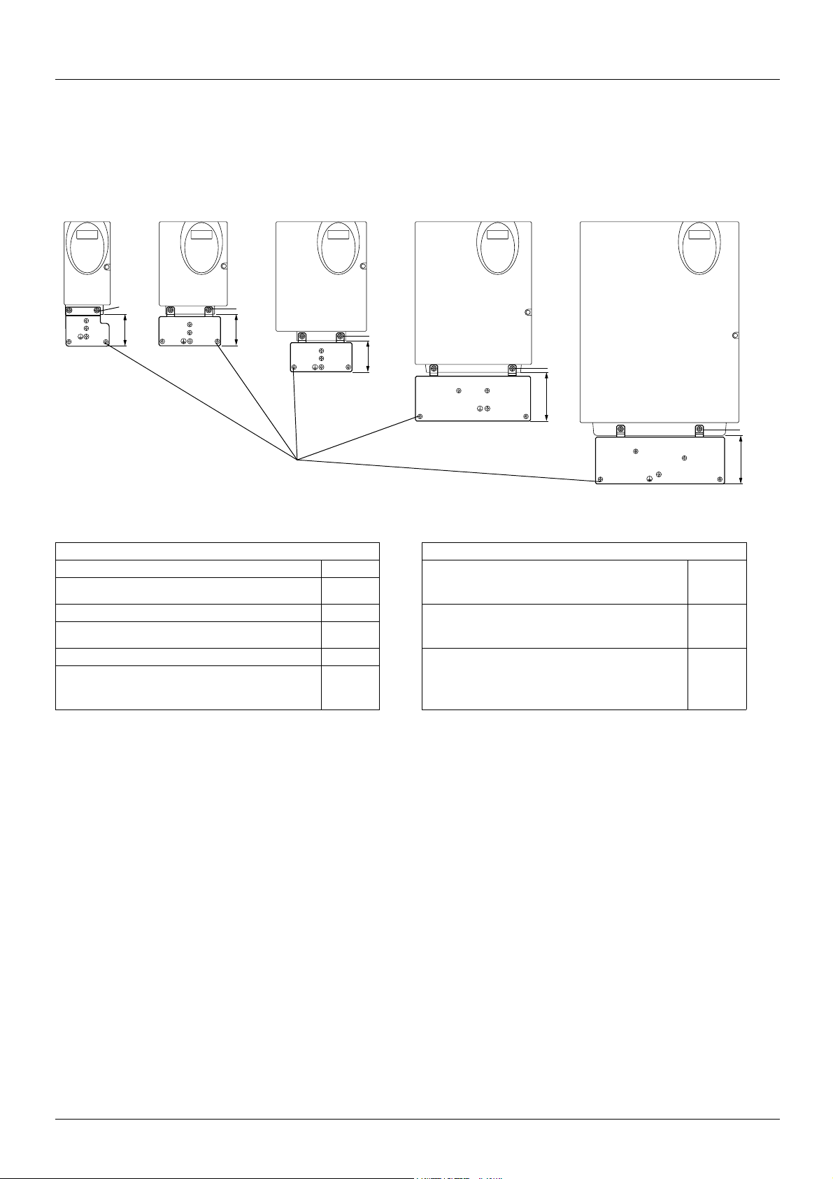
Electromagnetic compatibility
EMC mounting plate: Supplied with the drive
Fix the EMC equipotentiality mounting plate to the holes in the ATV 31 heatsink using the 2 screws supplied, as shown in the drawings
below.
Size 1 - 4 Size 5 -6
2
50
Screws supplied:
4 x M4 screws for fixing the EMC clamps (clamps not supplied)
1 x M5 screw for ground
ATV31 ATV31
H018M3X, H037M3X Size 1 HU22M2, HU30M3X, HU40M3X,
H055M3X, H075M3X Size 2
H018M2, H037M2 Size 3 HU55M3X, HU75M3X,
H055M2, H075M2 Size 4
HU11M3X, HU15M3X Size 5 HD11M3X, HD15M3X,
HU11M2, HU15M2, HU22M3X,
H037N4, H055N4, H075N4, HU11N4, HU15N4,
H075S6X, HU15S6X
2
49
Size 7
Size 6
48
Size 8 Size 9
2
2
75
HU22N4, HU30N4, HU40N4,
HU22S6X, HU40S6X
HU55N4, HU75N4,
HU55S6X, HU75S6X
HD11N4, HD15N4,
HD11S6X, HD15S6X
2
75
Size 7
Size 8
Size 9
7
Page 9

Wiring
Access to terminals
To access the terminals, open the cover as shown in the example below.
Example ATV31HU11M2
Power terminals
Connect the power terminals before connecting the control terminals.
Power terminal characteristics
Altivar ATV 31 Maximum connection capacity Tightening torque
AWG mm
H018M2, H037M2, H055M2, H075M2,
H018M3X, H037M3X, H055M3X, H075M3X, HU11M3X, HU15M3X
HU11M2, HU15M2, HU22M2,
HU22M3X, HU30M3X, HU40M3X,
H037N4, H055N4, H075N4, HU11N4,HU15N4, HU22N4, HU30N4, HU40N4
H075S6X, HU15S6X, HU22S6X, HU40S6X
HU55M3X, HU75M3X,
HU55N4, HU75N4,
HU55S6X, HU75S6X
HD11M3X, HD15M3X,
HD11N4, HD15N4,
HD11S6X, HD15S6X
AWG 14 2.5 0.8
AWG 10 6 1.2
AWG 6 16 2.5
AWG 3 25 4.5
Power terminal functions
Terminal Function For Altivar ATV 31
t
R/L1
S/L2
R/L1
S/L2
T/L3
PO DC bus + polarity All ratings
PA/+ Output to braking resistor (+ polarity) All ratings
PB Output to braking resistor All ratings
PC/- DC bus - polarity All ratings
U/T1
V/T2
W/T3
Ground terminal All ratings
ATV31
ATV31
ATV31
ppppM2
ppppM3X
ppppN4
ppppS6X
Power supply ATV31
Outputs to the motor All ratings
2
in Nm
Never remove the commoning link between PO and PA/+. The PO and PA/+ terminal screws must always be fully
tightened as a high current flows through the commoning link.
8
Page 10

Wiring
Arrangement of the power terminals
ATV 31H018M3X, H037M3X, H055M3X, H075M3X
T/L3R/L1 S/L2
P0 PA/+ PB PC/- U/T1 V/T2 W/T3
ATV 31HU11M3X, HU15M3X, HU22M3X, HU30M3X, HU40M3X,
H037N4, H055N4, H075N4, HU11N4, HU15N4, HU22N4,
HU30N4, HU40N4, H075S6X, HU15S6X, HU22S6X,
HU40S6X
R/L1 S/L2 T/L3
P0 PA/+ PB PC/- U/T1 V/T2 W/T3
ATV 31H018M2, H037M2, H055M2, H075M2
R/L1 S/L2
P0 PA/+ PB PC/- U/T1 V/T2 W/T3
ATV 31HU11M2, HU15M2, HU22M2
R/L1 S/L2
P0 PA/+ PB PC/- U/T1 V/T2 W/T3
ATV 31HU55M3X, HU75M3X, HU55N4, HU75N4, HU55S6X, HU75S6X
R/L1 S/L2 T/L3 P0 PA/+ PB PC/- U/T1 V/T2 W/T3
ATV 31HD11M3X, HD15M3X, HD11N4, HD15N4, HD11S6X, HD15S6X
R/L1 S/L2 T/L3 P0 PA/+ PB PC/- U/T1 V/T2 W/T3
9
Page 11

Wiring
Control terminals
Logic input
configuration
switch
RJ45
connector
- Maximum connection capacity: 2.5 mm2 - AWG 14
- Max. tightening torque: 0.6 Nm
Source
CLI
SINK
COM
AI1
10V
AI3
AI2
COM
AOV
RJ45
AOC
R1A
R1B
LI4
24V
R1C
LI5
LI1
R2A
LI6
LI2
R2C
CLI
LI3
Control
terminals
10
Page 12

Wiring
Control terminals
Arrangement, characteristics and functions of the control terminals
Terminal Function Electrical characteristics
R1A
R1B
R1C
R2A
R2C
COM Analog I/O common 0 V
AI1 Analog voltage input Analog input 0 + 10 V (max. safe voltage 30 V)
10 V Power supply for setpoint
AI2 Analog voltage input Bipolar analog input 0 ± 10 V (max. safe voltage ± 30 V)
Common point C/O contact (R1C) of
programmable relay R1
N/O contact of programmable relay R2
potentiometer
1 to 10 k
Ω
• Min. switching capacity: 10 mA for 5 V
• Max. switching capacity on resistive load (cos ϕ = 1 and L/R = 0 ms):
5 A for 250 V
• Max. switching capacity on inductive load (cos ϕ = 0.4 and L/R = 7 ms):
1.5 A for 250 V
• Sampling time 8 ms
• Service life: 100,000 operations at max. switching power
1,000,000 operations at min. switching power
• Impedance 30 k
• Resolution 0.01 V, 10-bit converter
• Precision ± 4.3%, linearity ± 0.2%, of max. value
• Sampling time 8 ms
• Operation with shielded cable 100 m max.
+10 V (+ 8% - 0), 10 mA max, protected against short-circuits and overloads
The + or - polarity of the voltage on AI2 affects the direction of the setpoint and
therefore the direction of operation.
• Impedance 30 k
• Resolution 0.01 V, 10-bit + sign converter
• Precision ± 4.3%, linearity ± 0.2%, of max. value
• Sampling time 8 ms
• Operation with shielded cable 100 m max.
a and 30 V c
a and 30 V c
Ω
Ω
c
AI3 Analog current input Analog input X - Y mA. X and Y can be programmed from 0 to 20 mA
COM Analog I/O common 0 V
AOV
AOC
24 V Logic input power supply + 24 V protected against short-circuits and overloads, min. 19 V, max. 30 V
LI1
LI2
LI3
LI4
LI5
LI6
CLI Logic input common See page 12.
Analog voltage output AOV
or
Analog current output AOC
or
Logic voltage output AOC
AOV or AOC can be assigned
(either, but not both)
Logic inputs Programmable logic inputs
Logic inputs Programmable logic inputs
• Impedance 250
• Resolution 0.02 mA, 10-bit converter
• Precision ± 4.3%, linearity ± 0.2%, of max. value
• Sampling time 8 ms
Analog output 0 to 10 V, min. load impedance 470
or
Analog output X - Y mA. X and Y can be programmed from 0 to 20 mA,
max. load impedance 800
• Resolution 8 bits (1)
• Precision ± 1% (1)
• Linearity ± 0.2% (1)
• Sampling time 8 ms
This analog output can be configured as a 24 V logic output on AOC, min. load
impedance 1.2 k
(1) Characteristics of digital/analog converter.
Max. customer current available 100 mA
• + 24 V power supply (max. 30 V)
• Impedance 3.5 k
• State 0 if < 5 V, state 1 if > 11 V (voltage difference between LI- and CLI)
• Sampling time 4 ms
• + 24 V power supply (max. 30 V)
• Impedance 3.5 k
• State 0 if < 5 V, state 1 if > 11 V (voltage difference between LI- and CLI)
• Sampling time 4 ms
Ω
Ω
Ω
Ω.
Ω
Ω
11
Page 13

Wiring
Wiring diagram for factory settings
ATV31ppppM2
Single-phase supply
(1)
S / L2
U1
R / L1
R / L1
U / T1
V1
3 a
M
S / L2
V / T2
(1)
T / L3
W / T3
W1
ATV31
3-phase supply
(2)
R1A
R1B
R1C
P0
Braking resistor,
if used
ppppM3X/N4/S6X
LI1
PB
R2C
PC / -
CLI
+10
Reference
potentiometer
R2A
PA / +
LI2
AI1
LI3
LI4
COM
X - Y mA
0 ± 10 V
LI5
AI3
LI6
AI2
24V
AOV
AOC
Using the analog output as a
logic output
COM
A0C
24 V relay
or
24 V PLC input
or
LED
(1) Line choke, if used (single phase or 3-phase)
(2) Fault relay contacts, for remote indication of the drive status.
Note: Fit interference suppressors to all inductive circuits near the drive or coupled to the same circuit (relays, contactors, solenoid valves,
etc).
Choice of associated components:
Please refer to the catalogue.
Logic input switch
This switch assigns the logic input common link to 0V, 24 V or "floating":
ATV31Hpppp
SOURCE
CLI
SINK
0V
ATV31Hpppp
CLI LI1 LIx
ATV31Hpppp
24V
CLI LI1 LIx
CLI at 0 V (factory setting)
CLI LI1 LIx
CLI "floating"
CLI at 24 V
12
Page 14
Wiring
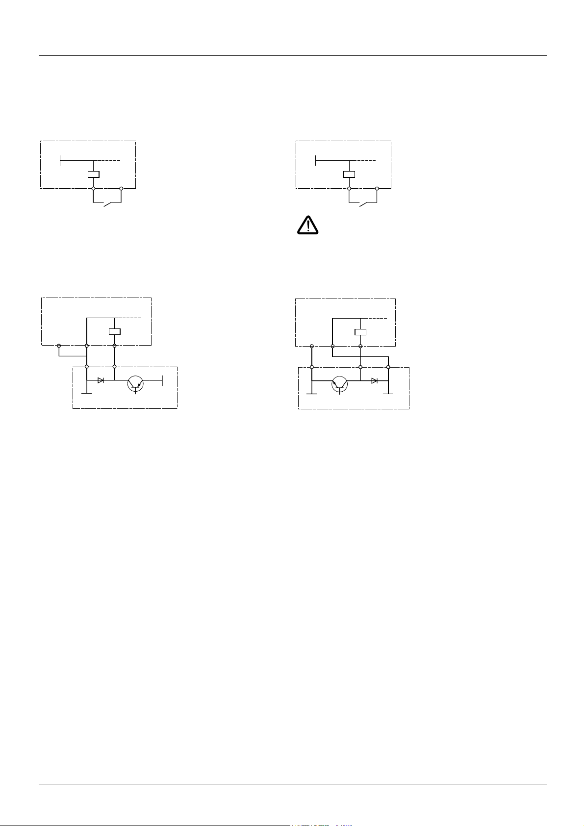
Examples of recommended circuit diagrams
Using volt-free contacts
• Switch in "Source" position
(ATV31 factory setting for types other than ATV31
ppppA)
• Switch in "SINK" position
(factory setting for ATV31ppppA)
ATV31Hpppp
0V
LI1
24V
ATV31Hpppp
24V
LI1
COM
In this instance, the common must never be connected to
earth or earth ground, as this presents a risk of unintended
equipment operation on the first insulation fault.
Using PLC transistor outputs
• Switch in CLI position • Switch in CLI position
ATV31Hpppp
LI1COM CLI
24V
0V
PLC
ATV31Hpppp
0V
CLI
PLC
LI1COM
24V
Wiring recommendations
Power
The drive must be earthed to conform with the regulations concerning high leakage currents (over 3.5 mA).
When upstream protection by means of a "residual current device" is required by the installation standards, a type A device should be used
for single-phase drives and type B for 3-phase drives. Choose a suitable model incorporating:
• HF current filtering
• A time delay which prevents tripping caused by the load from stray capacitance on power-up. The time delay is not possible for 30 mA
devices. In this case, choose devices with immunity against accidental tripping, for example RCDs with reinforced immunity from the
range (Merlin Gerin brand).
If the installation includes several drives, provide one "residual current device" per drive.
Keep the power cables separate from circuits in the installation with low-level signals (detectors, PLCs, measuring apparatus, video,
telephone).
If you are using cables > 50 m between the drive and the motor, add output filters (please refer to the catalogue).
Control
Keep the control circuits away from the power cables. For control and speed reference circuits, we recommend using shielded twisted
cables with a pitch of between 25 and 50 mm, connecting the shielding to ground at each end.
s.i
13
Page 15

Wiring
Operation on an IT system
IT system: Isolated or impedance earthed neutral.
Use a permanent insulation monitor compatible with non-linear loads (a Merlin Gerin type XM200, for example).
pppM2 and N4 drives feature built-in RFI filters. These filters can be isolated from ground for operation on an IT system as follows:
ATV 31
ATV31H018M2 to U22M2 and ATV31H037N4 to U40N4:
Pull out the jumper on the left of the ground terminal as illustrated below.
Normal
(filter connected)
IT system
(filter
disconnected)
ATV31HU55N4 to D15N4:
Move the cable tag on the top left of the power terminals as illustrated below (example ATV31HU55N4):
IT system
(filter disconnected)
Normal
(filter connected)
(factory setting)
14
Page 16
Wiring
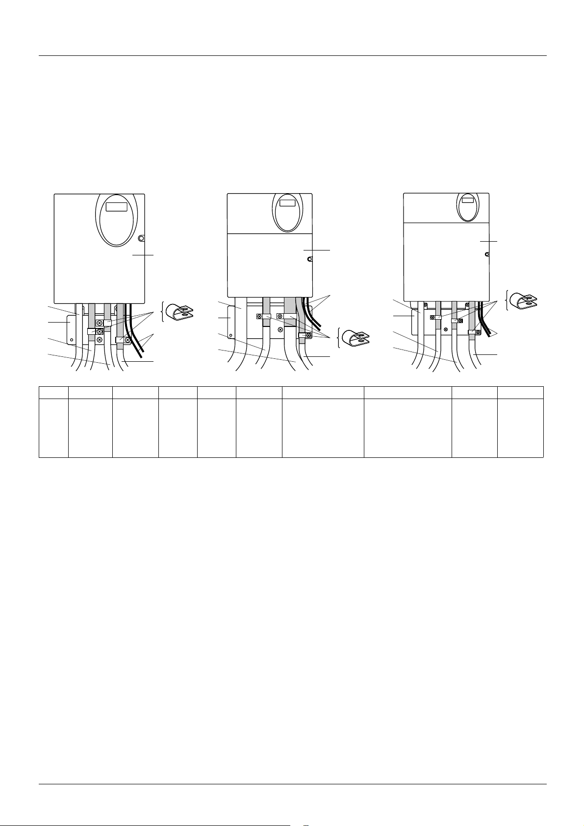
Electromagnetic compatibility
Principle
• Grounds between the drive, motor and cable shielding must have "high frequency" equipotentiality.
• Use shielded cables with shielding connected to ground throughout 360° at both ends for the motor cable 6, braking resistor (if used) 8,
and control-signalling cables 7. Metal ducting or conduit can be used for part of the shielding length provided that there is no break in
continuity.
• Ensure maximum separation between the power supply cable (line supply) and the motor cable.
Installation diagram (examples)
Sizes 1 to 7 Size 8 Size 9
2
3
1
8
6
5
4
7
3
1
8
6
2
4
5
7
Size 1 Size 2 Size 3 Size 4 Size 5 Size 6 Size 7 Size 8 Size 9
ATV31 H018M3X,
H037M3X
H055M3X,
H075M3X
H018M2,
H037M2
H055M2,
H075M2
HU11M3X,
HU15M3X
HU11M2, HU15M2
HU22M3X
H037N4, H055N4,
H075N4, HU11N4,
HU15N4
HU22M2
HU30M3X, HU40M3X
HU22N4, HU30N4,
HU40N4
HU22S6X, HU40S6X
H075S6X, HU15S6X
1 Sheet steel grounded plate supplied with the drive, to be fitted as indicated on the diagram.
2 Altivar 31
3 Non-shielded power supply wires or cable
2
3
1
8
6
HU55M3X,
HU75M3X
HU55N4,
HU75N4
HU55S6X,
HU75S6X
5
4
7
HD11M3X,
HD15M3X
HD11N4,
HD15N4
HD11S6X,
HD15S6X
4 Non-shielded wires for relay contacts
5 Fix and ground the shielding of cables 6, 7 and 8 as close as possible to the drive:
- Strip the shielding.
- Use stainless steel cable clamps of an appropriate size on the parts from which the shielding has been stripped, to attach them to the
plate 1.
The shielding must be clamped tightly enough to the metal plate to ensure correct contact.
6 Shielded cable for motor connection with shielding connected to ground at both ends.
The shielding must be continuous and intermediate terminals must be in EMC shielded metal boxes.
For 0.18 to 1.5 kW drives, if the switching frequency is higher than 12 kHz, use cables with low linear capacitance: max. 130 pF
(picoFarads) per metre.
7 Shielded cable for connecting the control/signalling wiring.
For applications requiring several conductors, use cables with a small cross-section (0.5 mm
2
).
The shielding must be connected to ground at both ends. The shielding must be continuous and intermediate terminals must be in EMC
shielded metal boxes.
8 Shielded cable for connecting braking resistor (if fitted).
The shielding must be continuous and intermediate terminals must be in EMC shielded metal boxes.
Note:
• If using an additional input filter, it should be mounted under the drive and connected directly to the line supply via an unshielded cable.
Link 3 on the drive is then via the filter output cable.
• The HF equipotential ground connection between the drive, motor and cable shielding does not remove the need to connect the PE
protective conductors (green-yellow) to the appropriate terminals on each unit.
15
Page 17

VVDED303041EN
atv31h_installing manual_EN_V3
2005-02
 Loading...