

Phaseo power outage solution
User guide
03/2008
W9 1489436 10 11 A01

2

Table of Contents
Safety Information . . . . . . . . . . . . . . . . . . . . . . . . . . . . . . . . . . . . 5
About the Book . . . . . . . . . . . . . . . . . . . . . . . . . . . . . . . . . . . . . . .7
Chapter 1 Overview . . . . . . . . . . . . . . . . . . . . . . . . . . . . . . . . . . . . . . . . . . . .9
Overview . . . . . . . . . . . . . . . . . . . . . . . . . . . . . . . . . . . . . . . . . . . . . . . . . . . . . . . . 9
Overview of the solution . . . . . . . . . . . . . . . . . . . . . . . . . . . . . . . . . . . . . . . . . . . 10
Presentation of Battery Modules ABL 8BPK24A•• . . . . . . . . . . . . . . . . . . . . . . . 11
Presentation of Battery control modules ABL 8BBU24•00. . . . . . . . . . . . . . . . . 12
Chapter 2 Choice of solution components . . . . . . . . . . . . . . . . . . . . . . . . 15
Choice of components. . . . . . . . . . . . . . . . . . . . . . . . . . . . . . . . . . . . . . . . . . . . . 15
Chapter 3 Implementation stages. . . . . . . . . . . . . . . . . . . . . . . . . . . . . . . .19
Implementation stages . . . . . . . . . . . . . . . . . . . . . . . . . . . . . . . . . . . . . . . . . . . . 19
Chapter 4 Assembly and temperature conditions . . . . . . . . . . . . . . . . . .21
Presentation . . . . . . . . . . . . . . . . . . . . . . . . . . . . . . . . . . . . . . . . . . . . . . . . . . . . 21
Mounting of the Battery module . . . . . . . . . . . . . . . . . . . . . . . . . . . . . . . . . . . . . 22
Mounting of Battery control module. . . . . . . . . . . . . . . . . . . . . . . . . . . . . . . . . . . 26
Chapter 5 Wiring. . . . . . . . . . . . . . . . . . . . . . . . . . . . . . . . . . . . . . . . . . . . . .27
Overview . . . . . . . . . . . . . . . . . . . . . . . . . . . . . . . . . . . . . . . . . . . . . . . . . . . . . . . 27
24 VDC circuit wiring. . . . . . . . . . . . . . . . . . . . . . . . . . . . . . . . . . . . . . . . . . . . . . 28
Diagnostics contact and inhibition input wiring . . . . . . . . . . . . . . . . . . . . . . . . . . 33
Wiring of an auto power off circuit of the Battery Module . . . . . . . . . . . . . . . . . . 35
Chapter 6 Setup . . . . . . . . . . . . . . . . . . . . . . . . . . . . . . . . . . . . . . . . . . . . . .37
Overview . . . . . . . . . . . . . . . . . . . . . . . . . . . . . . . . . . . . . . . . . . . . . . . . . . . . . . . 37
User interface . . . . . . . . . . . . . . . . . . . . . . . . . . . . . . . . . . . . . . . . . . . . . . . . . . . 38
First powering on / Minimum setup . . . . . . . . . . . . . . . . . . . . . . . . . . . . . . . . . . . 40
The SETTINGS Menu . . . . . . . . . . . . . . . . . . . . . . . . . . . . . . . . . . . . . . . . . . . . . 42
Settings transfer by memory card type SR2 MEM02 . . . . . . . . . . . . . . . . . . . . . 47
3

Chapter 7 Diagnostic. . . . . . . . . . . . . . . . . . . . . . . . . . . . . . . . . . . . . . . . . . 51
Overview . . . . . . . . . . . . . . . . . . . . . . . . . . . . . . . . . . . . . . . . . . . . . . . . . . . . . . . 51
Diagnostic . . . . . . . . . . . . . . . . . . . . . . . . . . . . . . . . . . . . . . . . . . . . . . . . . . . . . . 52
Faults - causes - remedies. . . . . . . . . . . . . . . . . . . . . . . . . . . . . . . . . . . . . . . . . . 55
Chapter 8 Operation timing diagrams . . . . . . . . . . . . . . . . . . . . . . . . . . . . 57
Overview . . . . . . . . . . . . . . . . . . . . . . . . . . . . . . . . . . . . . . . . . . . . . . . . . . . . . . . 57
Timed function . . . . . . . . . . . . . . . . . . . . . . . . . . . . . . . . . . . . . . . . . . . . . . . . . . . 58
All functions (timed or max) : voltage feedback before module cut-off . . . . . . . . 59
Max function with long power outage (complete discharge of Battery module). . 60
Output behaviour in the case of overload or short-circuit . . . . . . . . . . . . . . . . . . 61
Chapter 9 Maintenance . . . . . . . . . . . . . . . . . . . . . . . . . . . . . . . . . . . . . . . . 63
Overview . . . . . . . . . . . . . . . . . . . . . . . . . . . . . . . . . . . . . . . . . . . . . . . . . . . . . . . 63
SERVICE menu . . . . . . . . . . . . . . . . . . . . . . . . . . . . . . . . . . . . . . . . . . . . . . . . . . 64
Battery modules replacement . . . . . . . . . . . . . . . . . . . . . . . . . . . . . . . . . . . . . . . 66
Appendices . . . . . . . . . . . . . . . . . . . . . . . . . . . . . . . . . . . . . . . . . . . . . . . 67
Overview . . . . . . . . . . . . . . . . . . . . . . . . . . . . . . . . . . . . . . . . . . . . . . . . . . . . . . . 67
Appendix A Characteristics. . . . . . . . . . . . . . . . . . . . . . . . . . . . . . . . . . . . . . 69
Overview . . . . . . . . . . . . . . . . . . . . . . . . . . . . . . . . . . . . . . . . . . . . . . . . . . . . . . . 69
Electrical Characteristics of the Battery control modules. . . . . . . . . . . . . . . . . . . 70
Operating and environmental characteristics of Battery control modules . . . . . . 71
Electrical characteristics of the Battery modules . . . . . . . . . . . . . . . . . . . . . . . . . 72
Operating and environmental characteristics of Battery modules . . . . . . . . . . . . 73
Appendix B Battery general information . . . . . . . . . . . . . . . . . . . . . . . . . . . 75
Battery Generalities . . . . . . . . . . . . . . . . . . . . . . . . . . . . . . . . . . . . . . . . . . . . . . . 75
Appendix C FAQ . . . . . . . . . . . . . . . . . . . . . . . . . . . . . . . . . . . . . . . . . . . . . . . 77
FAQ . . . . . . . . . . . . . . . . . . . . . . . . . . . . . . . . . . . . . . . . . . . . . . . . . . . . . . . . . . . 77
Glossary . . . . . . . . . . . . . . . . . . . . . . . . . . . . . . . . . . . . . . . . . . . . . . . 79
Index . . . . . . . . . . . . . . . . . . . . . . . . . . . . . . . . . . . . . . . . . . . . . . .81
4
Safety Information
§
Important Information
NOTICE Read these instructions carefully, and look at the equipment to become familiar with
the device before trying to install, operate, or maintain it. The following special
messages may appear throughout this documentation or on the equipment to warn
of potential hazards or to call attention to information that clarifies or simplifies a
procedure.
The addition of this symbol to a Danger or Warning safety label indicates
that an electrical hazard exists, which will result in personal injury if the
instructions are not followed.
This is the safety alert symbol. It is used to alert you to potential personal
injury hazards. Obey all safety messages that follow this symbol to avoid
possible injury or death.
DANGER
DANGER indicates an imminently hazardous situation, which, if not avoided, will
result in death or serious injury.
WARNING
WARNING indicates a potentially hazardous situation, which, if not avoided, can result
in death, serious injury, or equipment damage.
CAUTION
CAUTION indicates a potentially hazardous situation, which, if not avoided, can result
in injury or equipment damage.
W9 1489436 10 11 A01 03/2008 5

Safety Information
PLEASE NOTE Electrical equipment should be installed, operated, serviced, and maintained only by
qualified personnel. No responsibility is assumed by Schneider Electric for any
consequences arising out of the use of this material.
© 2008 Schneider Electric. All Rights Reserved.
6
W9 1489436 10 11 A01 03/2008
About the Book
At a Glance
Document Scope This user manual contains the necessary information for the implementation of the
Phaseo power outage solution.
Related
Documents
Title of Documentation Reference Number
Phaseo Universal power supply instruction sheet 1489414_01
Battery Control module instruction sheet 1489436_01
Battery module instruction sheet 1489436_06
User Comments We welcome your comments about this document. You can reach us by e-mail at
techpub@schneider-electric.com
W9 1489436 10 11 A01 03/2008 7

About the Book
8
W9 1489436 10 11 A01 03/2008

Overview
1
Overview
Introduction This chapter presents the constitutive elements of the Phaseo power outage
solution.
What's in this
Chapter?
This chapter contains the following topics:
Topic Page
Overview of the solution 10
Presentation of Battery modules ABL 8BPK24A•• 11
Presentation of Battery control modules ABL 8BBU24•00 12
W9 1489436 10 11 A01 03/2008 9
Overview
Overview of the solution
Introduction The Phaseo power outage solution allows the 24 VDC supply of the installation (or
with one part) in case there is a network voltage cut-off:
During the entire duration of the cut-off, in order to allow :
the continuity of the installation service.
During a limited time, in order to allow :
data backup,
the fallback of the actuators,
the startup of generators,
operating system shut-down,
data transmission by remote monitoring...
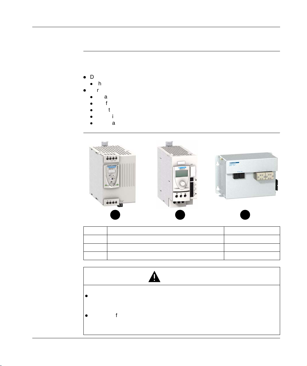
Constitution of
the solution
++
1
Marker Description Reference
1 Phaseo Universal power supply ABL 8•P•24••0
2 Battery control module ABL 8BBU24•00
3 Battery module ABL 8BPK24A••
RISKS OF EQUIPMENT DAMAGE
When the supply is provided by the Battery module, the voltage is not regulated
and can vary between 19 VDC and 28 VDC. It is suitable to check carefully that
the supplied circuits can support a voltage tension between these 2 values.
The use of batteries other than those included in the Battery modules
ABL 8BPK24A•• is not possible (risk of battery deterioration).
Failure to follow these instructions can result in injury or equipment damage.
2 3
CAUTION
10
W9 1489436 10 11 A01 03/2008
Presentation of Battery Modules ABL 8BPK24A••
Introduction Each Phaseo Battery module consists of:
2 lead sealed batteries mounted serially,
one fuse protection (automobile type).
The Phaseo Battery module range proposes 3 different battery capacities according
to the backup time and the current required for the application desired. See Choice
of components, p. 15.
Note: The Phaseo battery modules do not require maintenance. In the case of
failure, please replace the module set.
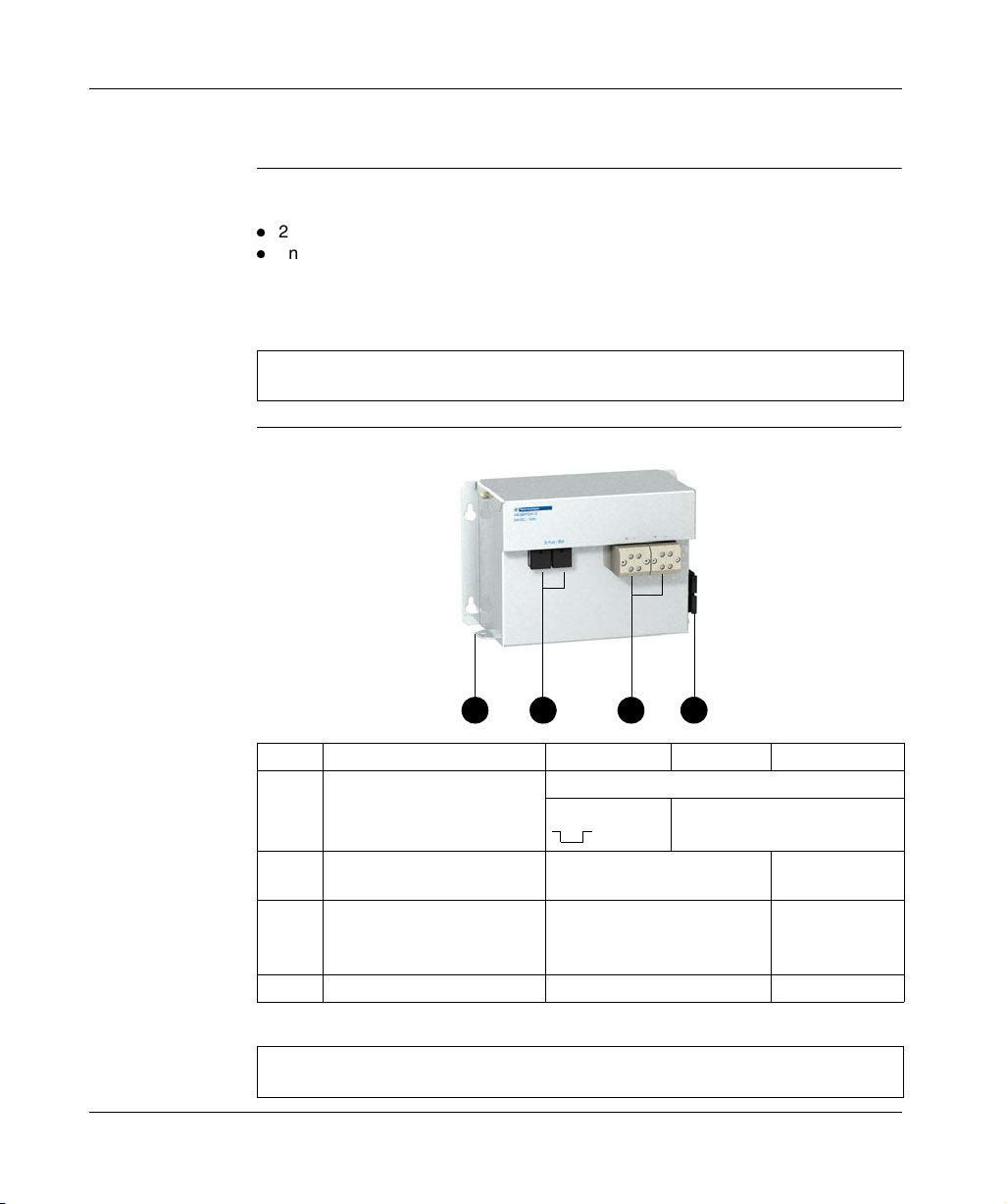
Description The scheme below presents the structure of the Phaseo Battery module:
Overview
1 2 3 4
Marker Description 3.2 Ah 7 Ah 12 Ah
1 Metal protective housing Bolt mounting by vertical or horizontal panel
Rail mounting
(1)
2 Protection fuse carrier and
shutdown of module
3 Terminal block of the 24 VDC
output voltage
4 Fuse storage attachment 1 attachment 2 attachments
(1)
Kit usage ABL 1A02
1 fuse carrier 2 fuse carriers
1 block
2
10 mm
screw terminal block
-
2 blocks
10 mm2 screw
terminal block
Note: The fuses are delivered with the module, but not mounted, please mount
them by following the implementation. See Implementation stages, p. 19.
W9 1489436 10 11 A01 03/2008 11

Overview
Presentation of Battery control modules ABL 8BBU24•00
Introduction The battery Control modules ABL 8BBU24•00 allowing the following functions :
Optimize the use and life of the batteries:
charge if necessary and as a function of the ambient temperature,
shutdown of the Battery module before the deep discharge
maintenance charge to compensate for self-discharge,
measurement of Battery module ageing
Automatic switch without interruption between power supply and battery:
adjustable operating time on the battery (holding time),
diagnostic of the system state.
The range of the Phaseo battery Control module consists of 2 modules according to
the maximum usage current (20 A or 40 A). See Choice of components, p. 15.
(1)
Important: When the Battery control module ABL 8BBU24•00 is not supplied by
the power supply ABL 8RP••/ABL 8WP••, the Battery module ABL 8BPK24A••
continues to provide a residual current necessary for the power supply of the module
electronics.
In the case of prolonged absence of the power supply voltage in the IN+ and INterminals, it is advisable to unplug the Battery module by removing its fuse(s) in
order to avoid deep discharge.
When this power-off is expected (machine transport or requested power-off), it is
also recommended to turn on the entire control module and Battery module until the
batteries are charged completely (battery icon OK on the display).
It is also possible to insert a contactor between the Battery module and the Battery
control module in order to execute an automatic cut-off (see Wiring of an auto power
off circuit of the Battery Module, p. 35).
(1)
,
12
W9 1489436 10 11 A01 03/2008
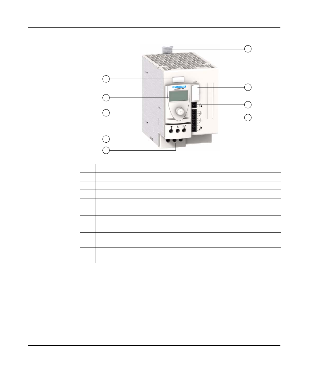
Description The scheme below presents the structure of the Battery control module:
6
1
7
2
8
3
4
5
9
N° Description
1 Click-on marker label
2 LCD display
3 Browse selection button
4 Grounded lug
5 24 VDC I/Os and the Battery module terminals
6 Mounting flange on DIN rail
7 Memory card (SR2 MEM02) slot to backup and copy configuration settings
8 2-point removable screw terminal block for the input terminal of the 'inhibition of the
Battery module voltage'
9 9-point removable screw terminal block for the input terminal of diagnostic contacts
(power supply presence, alarm and battery presence)
Overview
W9 1489436 10 11 A01 03/2008 13

Overview
14
W9 1489436 10 11 A01 03/2008

Choice of solution components
Choice of components
Introduction The application settings to be considered in the component choice are :
the current to be provided during t2 backup (holding current),
the t2 backup time (see timing diagram below).
AC input voltage
t
DC output voltage
2
t2
Guidance in
choosing
W9 1489436 10 11 A01 03/2008 15
According to the necessary holding current and desired backup time, the table below
indicates the associations of appropriate modules.
Note: This table is based on the characteristics of new Battery module. At the end
of life, once the autonomy of a battery is capable of being divided by 2, it is suitable
to take this into account when choosing the module(s) by multiplying the holding
time by 2 if desired to guarantee the holding time during the life of the modules. For
backup times greater than 5 hours, refer to the table on the following page.
t
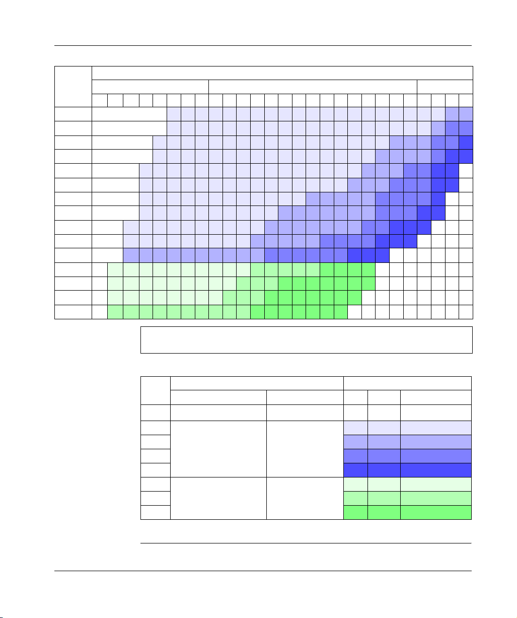
Choice of components
Holding
current
t2 holding time (see timing diagram)
Seconds Minutes Hours
0.1 0.2 0.5
12510301234567891015203040501235
1A 1 2 2 2 2 2 2 2 2 2 2 2 2 2 2 2 2 2 2 2 2 3 3
2 A 1
3 A 1
4 A 1
5 A 1
6 A 1
7 A 1
8 A 1
10 A 1
15 A 1
20 A 1
25 A 1
30 A 1
35 A 1
40 A 1
2 2 2 2 2 2 2 2 2 2 3 3 3 3 3 3 3 4 4 5 5 5
2 2 2 2 2 2 2 2 2 3 3 3 3 3 4 4 4 4 5 5 5
3 3 3 3 3 3 3 3 3 3 4 4 4 4 4 4 5 5 5
6 6 6 6 6 6 6 6 6 6 7 7 7 7 7 8 8 8 8
6 6 6 6 6 6 6 6 6 7 7 7 8 8 8 8 8 8 8
6 6 6 6 6 6 6 6 7 7 7 8 8 8 8 8 8 8
7 7 7 7 7 7 7 7 7 7 8 8 8 8 8 8 8
2 2 2 2 2 2 2 2 2 2 2 2 2 2 2 2 2 2 2 3 4 4
2 2 2 2 2 2 2 2 2 2 2 2 2 2 2 2 2 3 3 3 4 4 5
2 2 2 2 2 2 2 2 2 2 2 2 2 2 2 2 3 3 3 3 4 5 5
2 2 2 2 2 2 2 2 2 2 2 2 2 2 2 2 3 3 3 4 4 5 5
2 2 2 2 2 2 2 2 2 2 2 2 2 2 2 3 3 3 4 4 4 5 5
2 2 2 2 2 2 2 2 2 2 2 2 3 3 3 3 3 4 4 4 4 5
2 2 2 2 2 2 2 2 2 2 3 3 3 3 3 3 3 4 4 4 5 5
Note: Data for an ambient temperature of 20°C (68°F), the capacity of a battery
increases with temperature.
16
Associations proposed:
Code Module Battery module
Type Reference Qty. Type Reference
1
40 A Buffer Module
2 20 A Battery Control ABL 8BBU24200
3
4
5
6 40 A Battery Control ABL 8BBU24400
7
8
(1)
Solution for microbreaks (< 2 s), for more information please consult the catalog.
(1)
ABL 8BUF24400 - - ABL 8BUF24400
1 3.2 Ah ABL 8BPK24A03
1 7Ah ABL 8BPK24A07
1 12 Ah ABL 8BPK24A12
2 12 Ah ABL 8BPK24A12
1 7Ah ABL 8BPK24A07
1 12 Ah ABL 8BPK24A12
2 12 Ah ABL 8BPK24A12
W9 1489436 10 11 A01 03/2008
Choice of components
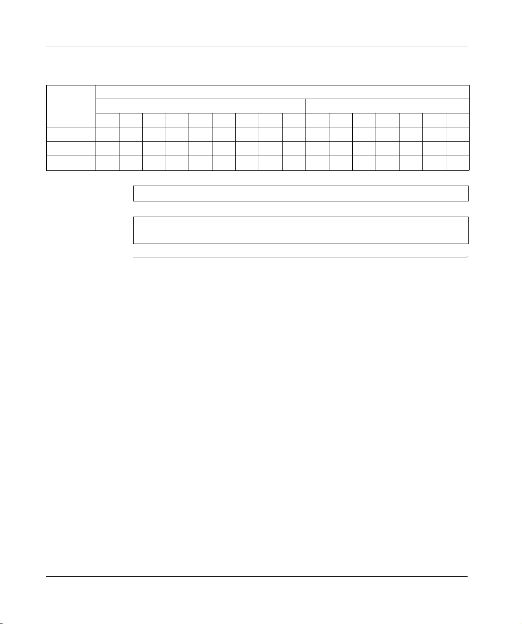
Discharge
current
Battery
module
capacity
3.2 Ah 8.4 6.3 4.9 4.2 3.6 3.1 2.8 2.6 2.3 2.0 1.1 0.86 0.50 0.38 0.30 0.16
7 Ah 18.2 13.6 11.0 9.0 7.7 6.8 6.1 5.6 5.0 4.2 2.5 1.8 1.2 0.80 0.64 0.35
12 Ah 31.3 23.4 18.6 15.5 13.3 11.6 10.5 9.6 8.6 7.1 4.2 3.1 2.0 1.3 1.1 0.60
t2 holding time (see timing diagram)
Minutes Hours
5 10152025303540451 2 3 5 8 1020
The following table indicates the likely discharge current (in A) as a function of the
desired holding time and the capacity of the Battery module:
Note: Data for an ambient temperature of 20°C (68°F).
Note: The holding times are multiplied by the number of parallel Battery modules
(3 MAXI).
W9 1489436 10 11 A01 03/2008 17

Choice of components
18
W9 1489436 10 11 A01 03/2008
Implementation stages
Implementation stages
3
Operation to be
To implement the Phaseo power outage solution proceed as follows:
followed
Stage Action See
1 Check that the products commissioned correspond to
commanded references.
2 Cut the primary power supply network. -
3 Install the Phaseo power supply. Service instruction delivered with the Phaseo
4 Install the Battery control module. Mounting of Battery control module, p. 26
5 Install the power supply.
connect the power supply to the network protection,
wire, if necessary, the diagnostics relay,
place the power supply switch to the MANU restart
mode.
6 Install the Battery module(s).
Do not plug in the fuse(s) for the moment.
7 Wiring:
connect the Battery control module and the Battery
module(s).
wire, if necessary, the 9-point terminal block of the
Battery control module.
8 Plug in the fuse(s) of the Battery module, then turn on the
power supply.
Note : A light sparkle may appear when plugging in the
fuses. This is not a failure.
9 Adjust and check the power supply:
adjust, if necessary, the output voltage,
check that the 2 lights are green.
Choice of solution components, p. 15
power supply, (Related Documents, p. 7).
Service instruction delivered with the Phaseo
power supply, (Related Documents, p. 7).
Mounting of the Battery module, p. 22
24 VDC circuit wiring, p. 28
Diagnostics contact and inhibition input
wiring, p. 33
-
Instruction sheet delivered with the Phaseo
power supply, (Related Documents, p. 7).
W9 1489436 10 11 A01 03/2008 19

Implementation stages
Stage Action See
10 Set up the Battery control module. First powering on / Minimum setup, p. 40
11 Wait for full charge of the Battery module before carrying
out a network outage test (up to 72h for a first
commissioning).
12 Check that the screen of the Battery control module is
green. It is possible to check also the information provided
by the output relays of the 9-point terminal block.
-
Diagnostic, p. 51
CAUTION
RISK OF EQUIPMENT DAMAGE
The power supply ABL 8•P must be configured in the manual reset mode (selector
on MANU). If the power supply is configured in the automatic reset mode (AUTO),
the Battery control module can be destroyed in the case of overcurrent in its output.
Failure to follow these instructions can result in injury or equipment damage.
20
W9 1489436 10 11 A01 03/2008

Assembly and temperature conditions
4
Presentation
Introduction This chapter presents the assembly and assembly conditions to be considered in the
installation of Battery modules and the Battery control module.
What's in this
Chapter?
This chapter contains the following topics:
Topic Page
Mounting of the Battery module 22
Mounting of Battery control module 26
W9 1489436 10 11 A01 03/2008 21

Assembly and temperature conditions
Mounting of the Battery module
Important Install the Battery module(s) in the freshest possible location. This prolongs their life
(see Lead Battery Generalities, p. 76).
Choice of
mounting
Depending on the temperature inside the enclosure, the following mountings are
recommended:
Temperature inside the enclosure = T Mounting
T ≤ 40 °C (104°F) Battery module inside the enclosure
T > 40 °C (104°F)
(No regulation of the temperature inside the
enclosure)
Battery module outside the enclosure
Note: The mounting with the Battery module inside the enclosure is favored in
order to allow the charge to be corrected as a function of temperature.
22
W9 1489436 10 11 A01 03/2008
Assembly and temperature conditions
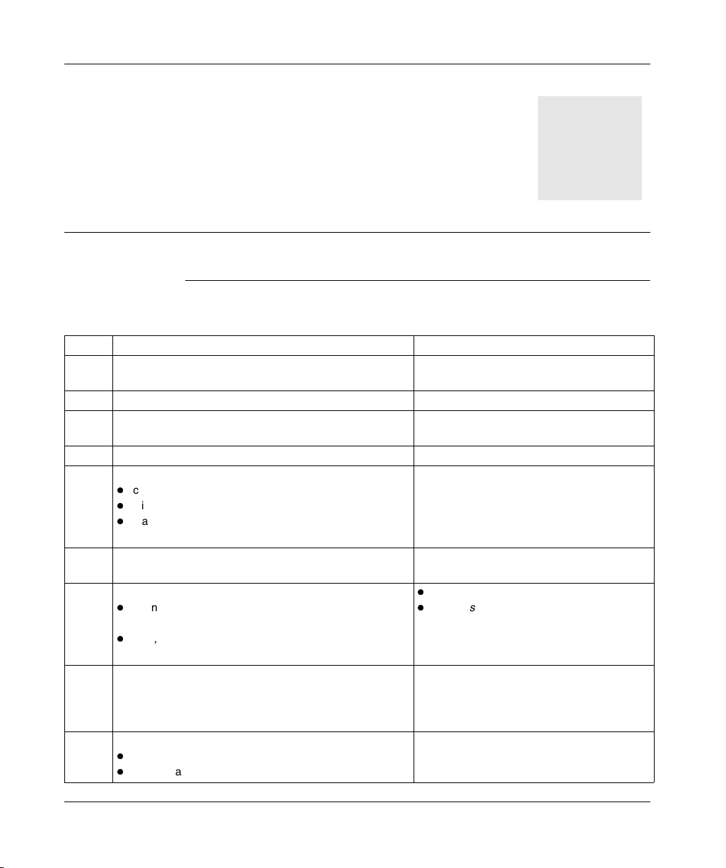
Mounting 1:
T ≤ 40°C (104°F)
Battery module below the enclosure :
MEM
FFO
1
+–
IN OUT
++
–
+
IN
–––
2
1
2
3
4
mralAUSP
5
6
7
+–
8
9
OUT
AUTO MANU
24V 28.8 V
++
IoutUout
–
–
<5m (196.85 in)
+–
Note: The charge voltage is adjusted automatically as a function of the
temperature measured by the control module.
Note: This mounting corresponds to the Battery module temperature setup in
Differential mode (see Battery module temperature, p. 46).
W9 1489436 10 11 A01 03/2008 23
Assembly and temperature conditions
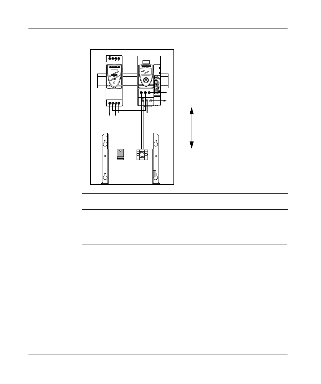
Mounting 2:
T > 40°C (104°F)
Battery module outside the enclosure, in a location where the temperature
approximates 20°C (68°F):
MEM
FFO
1
+–
IN OUT
++
–
+
–––
2
1
2
3
4
mralAUSP
5
6
7
+–
8
9
OUT
IN
AUTO MANU
24V 28.8 V
++
IoutUout
–
–
<5m (196.85 in)
+–
24
Note: This solution is only recommended if it is impossible to lower the temperature
inside the enclosure (ventilation, climatization). There is no automatic charge
voltage correction as a function of the temperature.
Note: This mounting corresponds to the Battery module temperature setup in
Absolute mode (see Battery module temperature, p. 46).
W9 1489436 10 11 A01 03/2008
Assembly and temperature conditions
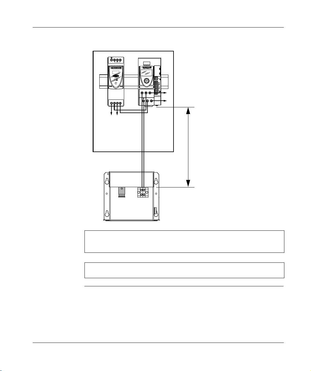
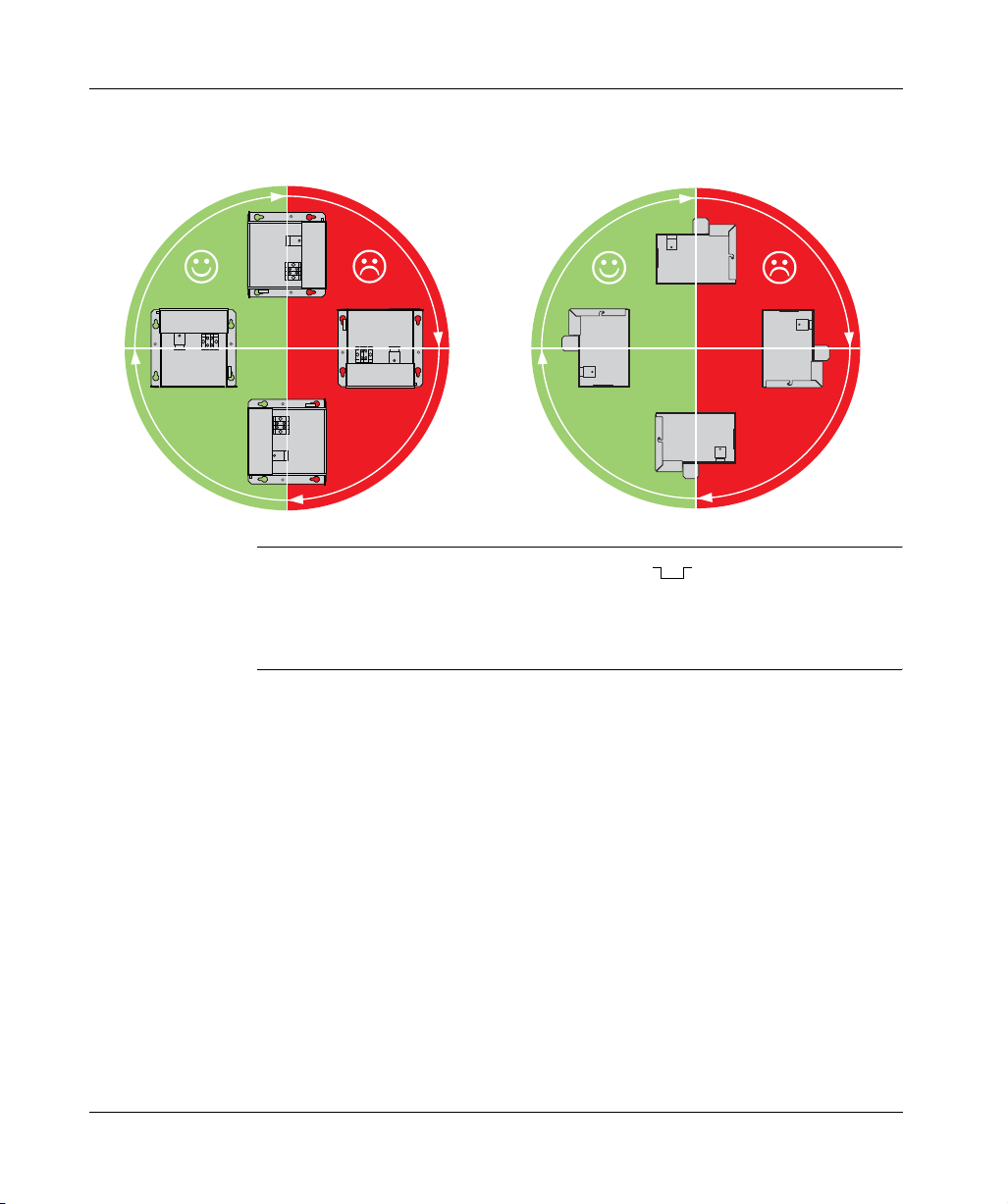
Mounting
position
The scheme below illustrates the positions to be considered during the mounting of
the Battery modules:
90°
+
–
+
0° 180°
–
+
–
+
–
270°
Dimensions and
mounting
The Battery modules are mounted by screw or rail for the module
ABL 8BPK24A03.
The module dimensions and drilling templates of mounting holes are located in the
instruction sheet of the Battery modules. See Related Documents, p. 7.
90°
0° 180°
270°
W9 1489436 10 11 A01 03/2008 25
 Loading...