

Operator Manual
For printer model:

Copyrights
Any unauthorized reproduction of the contents of this document, in part or whole, is strictly prohibited.
Limitation of Liability
SATO Corporation and its subsidiaries in Japan, the U.S. and other countri es make no representations or
warranties of any kind regarding this material, including, but not limited to, implied warranties of
merchantability and fitness for a particular purpose. SA T O Corporation shall not be held responsible for errors
contained herein or any omissions from this material or for any damages, whether direct, indirect, inciden tal or
consequential, in connection with the furnishing, distribution, performance or use of this material.
Specifications and contents in this document are subject to change without notice.
Trademarks
SATO is a registered trademark of SATO Holdings Corporation and its subsidiaries in Japan, the U.S. and
other countries.
Secure Digital (SD) Card is a registered trademark of the SD Card Association.
QR Code is a registered trademark of DENSO WAVE INCORPORATED.
Bluetooth is a trademark of Bluetooth SIG, Inc., U.S.A.
All other trademarks are the property of their respective owners.
Version: GBS-S84ex_S86ex-r01-17-10-14OM
© 2014 SATO Corporation. All rights reserved.

1
S84-ex/S86-ex Operator Manual
Table of Contents ................................................................................... 1
Before You Start..................................................................................... 7
1 Parts Identification............................................................................. 15
1.1 Printer Orientation ............................................................................................ 15
1.2 Parts Identification of the Printer .................................................................... 16
1.2.1 Front View ............................................................................................................... 16
1.2.2 Rear View................................................................................................................ 17
1.2.3 Internal View............................................................................................................ 18
1.3 Parts on the Operator Panel............................................................................. 19
1.3.1 Operator Panel........................................................................................................ 19
1.3.2 LED Indicator........................................................................................................... 20
2 Installing the Printer .......................................................................... 21
2.1 Installation Precautions.................................................................................... 21
2.2 Installation Space.............................................................................................. 22
2.2.1 Front View (S84-ex/S86-ex printer)......................................................................... 22
2.2.2 Rear View (S84-ex/S86-ex printer).......................................................................... 22
2.2.3 Media Dispensed View (S84-ex printer).................................................................. 23
2.2.4 Top View (S84-ex printer)........................................................................................ 24
2.2.5 Media Dispensed View (S86-ex printer).................................................................. 25
2.2.6 Top View (S86-ex printer)........................................................................................ 26
2.3 Installing the Printer onto a Support Structure/Applicator........................... 27
2.4 Checking the Bundled Accessories................................................................ 28
2.5 Connecting the Interface Cable ....................................................................... 29
2.5.1 Available Interfaces................................................................................................. 29
2.5.2 Interface Connections.............................................................................................. 29
2.5.3 Interface Settings..................................................................................................... 30
2.5.4 Interface Combination ............................................................................................. 31
2.6 Connecting the Power Cord............................................................................. 32
2.7 Power On/Off the Printer .................................................................................. 33
2.7.1 Power On the Printer............................................................................................... 33
2.7.2 Power Off the Printer............................................................................................... 33
2.8 Installing Optional Memory Storage................................................................ 34
2.8.1 Installing the Optional SD Card............................................................................... 34
2.8.2 Removing the Optional SD Card............................................................................. 34
2.8.3 Installing the Optional USB Memory........................................................................ 35
Table of Contents

Table of Contents
2
S84-ex/S86-ex Operator Manual
3 Loading the Ribbon and Media........................................................... 37
3.1 Checking the Ink Side of the Ribbon............................................................... 37
3.2 Loading the Ribbon .......................................................................................... 38
3.3 Removing the Ribbon....................................................................................... 41
3.4 Usable Media ..................................................................................................... 42
3.4.1 Adjusting the Position of the Media Sensor............................................................. 42
3.5 Loading Media................................................................................................... 43
3.5.1 Loading Label with Dispenser ................................................................................. 43
3.5.2 Loading Media without Using Dispenser................................................................. 46
4 Operation and Configuration.............................................................. 47
4.1 Display and Operation...................................................................................... 47
4.1.1 Normal Mode Display and Icons.............................................................................. 47
4.1.2 Setting Mode Menu and Icons................................................................................. 50
4.1.3 Error Display and Icons........................................................................................... 51
4.1.4 Setting Display......................................................................................................... 52
4.2 Operating Modes............................................................................................... 54
4.2.1 Online Mode/Pause Mode/Offline Mode.................................................................. 57
4.2.2 Adjusting the Display Brightness............................................................................. 58
4.2.3 Adjusting the Buzzer Volume .................................................................................. 58
4.2.4 Canceling the Print Job ........................................................................................... 59
4.2.5 Adjustment Mode..................................................................................................... 60
4.2.6 Work Shift Setting Mode.......................................................................................... 62
4.2.7 Simple Standalone Mode ........................................................................................ 64
4.2.8 Setting Mode Menu ................................................................................................. 67
4.2.9 User Mode............................................................................................................... 69
4.2.10 Interface Mode....................................................................................................... 74
4.2.11 Memory Mode........................................................................................................ 97
4.2.12 Service Mode....................................................................................................... 105
4.2.13 Advanced Mode................................................................................................... 126
4.2.14 Hex Dump Mode.................................................................................................. 144
4.2.15 Information Mode................................................................................................. 147
4.2.16 Test Print Mode................................................................................................... 150
4.2.17 Default Setting Mode........................................................................................... 153
4.2.18 Download Mode................................................................................................... 156
4.2.19 Upload Mode....................................................................................................... 161
4.2.20 Hidden Setting Mode........................................................................................... 163
4.2.21 Wireless LAN Certificate Download Mode........................................................... 164
4.2.22 Site Survey Mode................................................................................................ 166

Table of Contents
3
S84-ex/S86-ex Operator Manual
5 Cleaning and Performing Printer Adjustments................................ 171
5.1 Maintenance . ................................................................................................... 171
5.2 Maintenance of the Print Head and Platen Roller ........................................ 172
5.2.1 Maintenance using the Cleaning Kit...................................................................... 172
5.2.2 Maintenance using the Cleaning Sheet................................................................. 175
5.3 Adjusting the Base Reference Point ............................................................. 177
5.3.1 About the Base Reference Point........................................................................... 177
5.3.2 Adjusting the Print Position.................................................................................... 178
5.3.3 Adjusting the Media Stop Position......................................................................... 180
5.3.4 More about the Media Stop Position ..................................................................... 181
5.3.5 Limitation on Base Reference Point Adjustment................................................... 182
5.4 Adjusting the Print Quality............................................................................. 183
5.4.1 Adjustment of the Print Darkness.......................................................................... 183
5.4.2 Adjusting the Print Speed...................................................................................... 184
5.5 Adjusting the Media Sensors......................................................................... 186
5.5.1 Adjusting the Media Sensor Automatically............................................................ 186
5.5.2 Adjusting the I-mark Sensor Level Manually......................................................... 189
5.5.3 Adjusting the Gap Sensor Level Manually............................................................. 191
5.5.4 Adjusting the Paper End Sensor ........................................................................... 193
5.6 Adjusting the Head Pressure Balance .......................................................... 195
5.7 Adjusting the Head Position .......................................................................... 197
5.7.1 Left - Right Pressure Balance Setting ................................................................... 197
5.7.2 Front - Rear Head Alignment................................................................................. 198
5.8 Adjusting the Ribbon Tension Balance ........................................................ 199
6 Troubleshooting................................................................................ 201
6.1 When an Error Message Occurs.................................................................... 201
6.1.1 More Information about Command Error............................................................... 208
6.1.2 More Information about Head Check Function...................................................... 209
6.2 When a Warning Message Occurs ................................................................ 210
6.3 When the LED Lights Red/Blue ..................................................................... 212
6.4 Troubleshooting Table ................................................................................... 213
6.4.1 No Power/Nothing on the Screen.......................................................................... 213
6.4.2 Cannot Feed the Media......................................................................................... 213
6.4.3 Can Feed the Media but Cannot Print................................................................... 214
6.4.4 Bad Print Quality.................................................................................................... 215
6.4.5 Incorrect Print Position .......................................................................................... 216

Table of Contents
4
S84-ex/S86-ex Operator Manual
6.5 Interface Troubleshooting.............................................................................. 217
6.5.1 USB Interface........................................................................................................ 217
6.5.2 LAN Ethernet Interface.......................................................................................... 217
6.5.3 Bluetooth Interface (Optional)................................................................................ 217
6.5.4 RS-232C Interface................................................................................................. 218
6.5.5 IEEE1284 Interface ............................................................................................... 218
6.5.6 External Signal Interface (EXT)............................................................................. 218
6.5.7 Wireless LAN Interface (Optional)......................................................................... 219
7 Appendix........................................................................................... 221
7.1 List of Initial Values ........................................................................................ 221
7.1.1 Normal Mode......................................................................................................... 221
7.1.2 User Mode............................................................................................................. 221
7.1.3 Interface Mode....................................................................................................... 222
7.1.4 Memory Mode........................................................................................................ 224
7.1.5 Advanced Mode..................................................................................................... 225
7.1.6 Hex Dump Mode.................................................................................................... 227
7.1.7 Test Print Mode..................................................................................................... 227
7.1.8 Default Setting Mode............................................................................................. 228
7.1.9 Service Mode......................................................................................................... 228
7.1.10 Hidden Setting Mode........................................................................................... 229
7.1.11 Work Shift Setting Mode...................................................................................... 230
7.1.12 Simple Standalone Mode .................................................................................... 230
7.1.13 Wireless LAN Setting........................................................................................... 231
7.2 Media Sensor Positions and Media Stop Positions..................................... 235
7.3 About Compatible Mode................................................................................. 237
7.3.1 Compatible Mode .................................................................................................. 237
7.3.2 Compatible Mode - Print Head Width (only for S86-ex printer)............................. 237
7.3.3 Print Head Width and Printable Area Range......................................................... 239
7.4 LCD Power Saving Mode................................................................................ 241
7.5 Input/Output Signal of the External Signal................................................... 242
7.6 Notification Function ...................................................................................... 244
7.7 Replacing Consumable Parts ........................................................................ 246
7.7.1 Replacing the Print Head....................................................................................... 246
7.7.2 Replacing the Platen Roller................................................................................... 248
7.7.3 Replacing the Pressure Roller............................................................................... 250
7.7.4 Replacing the Media Feed Roller.......................................................................... 252
7.7.5 Replacing the Fan Filter ........................................................................................ 253
7.8 Media Motion of the Printer Operation.......................................................... 254
7.8.1 Feed Motion........................................................................................................... 254
7.8.2 Paper End.............................................................................................................. 254
7.8.3 Sensor Error.......................................................................................................... 257
7.8.4 Ribbon Error.......................................................................................................... 258
7.9 Print Speed and Media Size ........................................................................... 259

Table of Contents
5
S84-ex/S86-ex Operator Manual
7.10 Optional Ribbon Saver ................................................................................. 260
7.10.1 Ribbon Saver Operation...................................................................................... 260
7.10.2 Ribbon Saver Timing Charts ............................................................................... 261
7.10.3 Ribbon Saver Operation and Ribbon Consumption ............................................ 262
7.10.4 Ribbon Specification for the Ribbon Saver.......................................................... 265
7.10.5 Label Specification for the Ribbon Saver ............................................................ 265
7.11 Printer Specifications ................................................................................... 266
7.11.1 Hardware............................................................................................................. 266
7.11.2 Ribbon and Media ............................................................................................... 268
7.11.3 Interface............................................................................................................... 269
7.11.4 Built-in Functions................................................................................................. 269
7.11.5 Printer Languages............................................................................................... 270
7.11.6 Fonts/Symbols/Barcodes..................................................................................... 271
7.11.7 Options................................................................................................................ 273
7.11.8 Accessories......................................................................................................... 273
7.11.9 Standards............................................................................................................ 273
7.12 Interface Specifications................................................................................ 274
7.12.1 USB Interface...................................................................................................... 275
7.12.2 LAN Ethernet Interface........................................................................................ 276
7.12.3 RS-232C Interface............................................................................................... 277
7.12.4 IEEE1284 Interface ............................................................................................. 279
7.12.5 External Signal Interface (EXT)........................................................................... 281
7.12.6 Bluetooth Interface .............................................................................................. 292
7.12.7 Wireless LAN Interface........................................................................................ 293

Table of Contents
6
S84-ex/S86-ex Operator Manual
This page is intentionally left blank.

7
S84-ex/S86-ex Operator Manual
Thank you for purchasing this SATO S84-ex/S86-ex print engine (hereafter referred to as “the printer”).
This manual supplies basic information on how to operate the printer. Read the manual carefully to
understand each function before operation.
Features of the Product
This SATO S84-ex/S86-ex print engine is a high-performance, automated print/apply labeling system
with a user-friendly design and equipped with versatile functions. This print engine has a durable design
for non-stop operation.
The main features of the printer are as follows:
• Equipped with a two-color backlight LCD and a two-color status LED for improved monitoring of the
printer status.
• Durable design for harsh environment.
• High-speed throughput printing with maximum 16 ips print speed and adjustable backfeed speed
control.
• Print head can be replaced easily without using extra tools.
• New designed sensor cover with nonstick surface that can be easily removed and cleaned without any
tools.
• Easily upload/download data to/from an SD card or USB memory, or by using the SATO All In One
Tool application.
• Supports remote printer setting through the SATO All In One Tool application or a web browser.
• Supports a multi-language display menu and printing of Asian fonts.
• Supports emulations in standard firmware.
• Supports various communication interfaces.
• Supports SNTP protocol.
Before You Start

Before You Start
8
S84-ex/S86-ex Operator Manual
Safety Precautions
This section describes how to safely operate the printer. Be sure to read and understand all instructions
carefully before you install and use the printer.
Pictographic Symbols
This operator manual and printer labels use a variety of pictographic symbols. These symbols show the safe
and correct operation of the printer and how to prevent injury to others and property damage. The symbol
explanations are as follows.
Example Pictographs
Warning
The Warning symbol indicates that
you can cause death or serious
injury if you do not follow the
instruction or procedure.
Caution
The Caution symbol indicates that
you can cause injury or property
damage if you do not follow the
instruction or procedure.
The pictograph means “Caution is required”. The pictograph includes a
specified warning symbol (for example, the left symbol shows electric shock).
The pictograph means “Must not be done”. The pictograph includes a specified
prohibited symbol (for example, the left symbol means “Disassembly prohibited”).
The pictograph means “Must be done”. The pictograph includes a specified
mandate action symbol (for example, the left symbol means “Disconnect the
power plug from the outlet”).
Warning
Place the printer on a stable area.
• Place the printer on a stable area. Do not
place the printer on an unstable table,
slanted surface or an area subject to
strong vibration. If the printer falls off or
topples, it could cause injury to
someone.
Do not place containers filled with liquid on the
printer.
• Do not place flower vases, cups, or other
containers filled with liquids, on the
printer. If any liquid spills into the printer,
immediately power off the printer and
disconnect the power plug from the
outlet. Then contact your SATO reseller
or technical support center. If you
operate the printer in this condition, it
could cause a fire or electric shock.
Do not place objects into the printer.
• Do not place metal or flammable objects
inside the printer’s opening. If a foreign
object gets into the printer, immediately
power off the printer and disconnect the
power plug from the outlet. Then contact
your SATO reseller or technical support
center. If you operate the printer in this
condition, it could cause a fire or electric
shock.
Do not use other than the specified voltage.
• Do not use oth e r tha n the specified
voltage. Doing so could cause a fire or
electric shock.

Before You Start
9
S84-ex/S86-ex Operator Manual
Warning
Always ground connections.
• Always connect the printer’s ground wire
to a ground. Not grounding the ground
wire could cause an electric shock.
Handling the power cord
• Do not break or change the power cord.
Do not place heavy objects on the power
cord, heat it, or pull it. Doing so could
cause damage to the power cord and
cause a fire or electric shock.
• If the power cor d beco m es dam a ge d
(core is exposed, wires broken, etc.),
contact your SATO reseller or technical
support center. Using the power cord in
this condition could cause a fire or
electric shock.
• Do not change, overly bend, twist, or pull
the power cord. Using the power cord in
such a way could cause a fire or electric
shock.
When the printer has been dropped or broken
• If the print er is drop p ed or br ok en ,
immediately power off the printer and
disconnect the power plug from the
outlet. Contact your SATO reseller or
technical support center. Using the
printer in this condition could cause a fire
or electric shock.
Do not use the printer when something is
unusual about it.
• Continuing to use the printer in the event
something is unusual about it, such as
smoke or unusual smells coming from it,
could cause a fire or electric shock.
Immediately power off the printer and
disconnect the power plug from the
outlet. Then contact your SATO reseller
or technical support center for repairs.
Under no circumstances should you
attempt repairs on your own; it is too
dangerous.
Do not disassemble the printer.
• Do not disassemble or modify the printer.
Doing so could cause a fire or electric
shock. Contact your SATO reseller or
technical support center to perform
internal inspections, adjustments, and
repairs.
Using the head cleaning fluid
• Use of flame or heat around the head
cleaning fluid is prohibited. Do not heat it
or subject it to flames.
• Keep the flu id ou t of re ac h of childr en . If
a child accidentally drinks the fluid,
immediately consult with a physician.
Print head
• The print head will become hot after
printing. Be careful not to touch it when
replacing media or cleaning immediately
after printing, to avoid being burned.
• Touching the edge of the print head
immediately after printing could cause an
injury. Use caution when replacing the
media or cleaning the print head.
• Never replace the print head if you have
not received the correct training.

Before You Start
10
S84-ex/S86-ex Operator Manual
Caution
Do not use in areas of high humidity.
• Do not use the printer in areas of high
humidity or where condensation forms. If
condensation forms, immediately power
off the printer and do not use the printer
until it dries. Using the printer while
condensation is on it could cause an
electric shock.
Carrying the printer
• When moving the printer, always
disconnect the power cord from the
outlet and check to make sure that all
external wires are disconnected before
moving it. Moving the printer with the
wires still connected could cause
damage to the cords or connecting
wires, resulting in a fire or electric shock.
• Do not carry the printer while it contains
media. The media could fall out and
cause an injury.
• When setting the printer on the floor or a
stand, be sure not to get your fingers or
hands pinched under the printer feet.
Power supply
• If your hands are wet, do not operate the
power switch, connect the power cord or
disconnect the power cord. Doing so
could cause an electric shock.
Power cord
• Keep the power cord away from hot
devices. Placing the power cord near hot
devices could cause the cord’s covering
to melt and cause a fire or electric shock.
• When disconnecting the power cord from
the outlet, be sure to hold the plug.
Pulling the cord could expose or break
the wires and cause a fire or electric
shock.
• The power cord set that comes with the
printer is designed especially for this
printer. Do not use it with any other
electrical devices.
To p cover
• Be careful not to get your fingers pinched
when opening or closing the top cover.
Also, be careful that the top cover does
not slip off and drop.
Loading media
• When loading a media roll, be careful not
to get your fingers pinched between the
media roll and the supply unit.
When not using the printer for a long time
• When not using the printer for a long
time, disconnect the power cord from the
outlet to maintain safety.
During maintenance and cleaning
• When maintaining and cleaning the
printer, disconnect the power cord from
the outlet to maintain safety.

Before You Start
11
S84-ex/S86-ex Operator Manual
Precautions for Installation and Handling
Printer operation can be affected by the printer environment.
Refer to the following instructions for installation and handling of the S84-ex/S86-ex printer.
Select a Safe Location
Power Supply
Place the printer on a surface that is flat and lev el.
If the surface is not flat and level, this may cause bad
print quality. This may also cause a malfunction and
decrease the life span of the printer.
Do not place the printer on a location that
produces vibration.
Giving serious vibration or shock to the printer may
cause a malfunction and shorten the life span of the
printer.
Keep the printer out of high temperature and
humidity.
Avoid locations subject to extreme or fast changes in
temperature or humidity.
Do not place the printer in a location subject to
water or oil.
Do not place the printer in a location where it will be
exposed to water or oil. Water or oil entering inside
the printer may cause a fire, electric shock or
malfunction.
Avoid dust.
Dust build up may result in bad print quality.
Keep out of direct sunlight.
This printer has a built-in optical sensor. Exposure to
direct sunlight will make the sensor less responsive
and may cause the media to be sensed incorrectly.
Close the top cover when printing.
This printer requires an AC power supply.
Be sure to connect the printer to an AC power
supply.
Connect the power cord to a grounded power
outlet.
Make sure that the printer is connected to a
grounded power outlet.
Supply a stable source of electricity to the printer.
When using the printer, do not share its power outlet
with other electrical devices that could cause power
fluctuations and performance issues with your
printer.

Before You Start
12
S84-ex/S86-ex Operator Manual
Regulatory Approval
FCC Warning
This equipment has been tested and found to comply with the limits for a Class A digital device, pursuant
to Part 15 of the FCC Rules. These limits are designed to provide reasonable protection against harmful
interference when the equipment is operated in a commercial environment. This equipment generates,
uses, and can radiate radio frequency energy, and if not installed and used in accordance with the
instructions, may cause harmful interference to radio communications. Operation of this equipment in a
residential area is likely to cause harmful interference in which case the user will be required to correct
the interference at his own expense.
FCC Statement for Optional Wireless LAN
This device complies with RF radiation exposure limits set forth for an uncontrolled environment.
The antenna used for this transmitter must be installed to provide a separation distance of at least 20 cm
from all people and must not be collocated or operating in conjunction with any other antenna or
transmitter.
Bluetooth/Wireless Communication
Compliance Statement
This product has been certified for compliance with the relevant radio interference regulations of your
country or region. To make sure continued compliance, do not:
• Disassemble or modify this product.
• Remove the certificate label (serial number seal) affixed to this product.
Use of this product near microwave and/or other wireless LAN equipment, or where static electricity or
radio interference is present, may shorten the communication distance, or even disable commun ic atio n.

Before You Start
13
S84-ex/S86-ex Operator Manual
Industry Canada (IC) Statement for Bluetooth
This device complies with Industry Canada license-exempt RSS standard(s).
Operation is subject to the following two conditions:
• This device may not cause interference.
• This device must accept any interference, including interference that may cause undesired operation
of the device.
This equipment complies with IC radiation exposure limits set forth for an uncontrolled environment and
meets RSS-102 of the IC radio frequency (RF) Exposure rules. This equipment should be installed and
operated keeping the radiator at least 20 cm or more away from person’s body (excluding extremities:
hands, wrists, feet and ankles).
Le présent appareil est conforme aux CNR d’Industrie Canada applicables aux appareils radio exempts
de licence. L’exploitation est autorisée aux deux conditions suivantes :
• L’appareil ne doit pas produire de brouillage.
• L’utilisateur de l’appareil doit accepter tout brouillage radioélectrique subi, même si le brouillage est
susceptible d’en compromettre le fonctionnement.
Cet équipement est conforme aux limites d’exposition aux rayonnements énoncées pour un
environnement non contrôlé et respecte les règles d’exposition aux fréquences radioélectriques (RF)
CNR-102 de l’IC. Cet équipement doit être installé et utilisé en gardant une distance de 20 cm ou plus
entre le dispositif rayonnant et le corps (à l’exception des extrémités : mains, poignets, pieds et
chevilles).
Disposal of Old Electrical & Electronic Equipment (Applicable in the European Union
and other European countries with separate collection systems)
A product marked with this symbol on itself or on its packaging shall not be treated as
household waste. Instead, it shall be handed over to an appropriate collection point for
the recycling of electrical and electronic equipment in accordance with local regulations.
Inappropriate waste handling of this product may cause detrimental consequences for
the environment and damage to human health. The recycling of materials will help to
conserve natural resources and contribute to your community. For more detailed
information on recycling of this product, contact your local municipal organization, your
household waste disposal service or the dealer where you purchased the product.
EN55022 Warning
This is a class A product.
In a domestic environment, this product may cause radio interference, in which case the user may be
required to take adequate measures.
EN55022 Warnung
Dies ist eine Klasse A Produkt.
In einer häuslichen Umgebung verursacht dieses Produkt vielleicht Radioeinmischung in dem Fall, der
vom Benutzer vielleicht verlangt wird, adäquate Maßnahmen zu ergreifen.
Before You Start
14
S84-ex/S86-ex Operator Manual
㺞⽰䈛ᴿ∈ᴿᇩ⢟䍞㠩ቇ൞䈛䜞ԬⲺḆжൽ䍞ᶆѣⲺ䠅䎻࠰SJ/T113632006ć⭫ᆆؗᚥӝѣᴿ∈ᴿᇩ⢟䍞Ⲻ䲆䠅㾷≸ĈⲺḽ㿺ᇐȾ
(Pb)
(Hg)
ᵰಞ〦ᶗᖘ⸷ᢉদᵰ
䜞Ԭ〦
ᴿ∈ᴿᇩ⢟䍞ᡌݹ㍖
䫻⊔
দ⭫䐥ᶵ
(Cd)
䭿
(Cr6+)
ޣԭ䬢
(PBB)
ཐ⓪㚊㤥
(PBDE)
ཐ⓪ӂ
㤥䟐
⭫ⓆȽӚ⍷䖢ᦘಞ
⭫⊖
✣ᮅཪ
Ƚ
⏨Წᱴ⽰ኅ
⭫ࣞᵰ
Ƚ
࠽㓮ᵰ
ṇ㜸ABS
Ƚ
PCㅿ
䠇ኔ䫷
Ƚ
䶔䫷䠇ኔ
⭫㔼ㅿ
㻻ᶆᯏ㓮ⴈㅿ
㺞⽰䈛ᴿ∈ᴿᇩ⢟䍞൞䈛䜞Ԭᡶᴿൽ䍞ᶆѣⲺ䠅ൽ൞SJ/T11363-2006 ć⭫
ᆆؗᚥӝѣᴿ∈ᴿᇩ⢟䍞Ⲻ䲆䠅㾷≸ĈⲺḽ㿺ᇐԛсȾ
ᵢḽᘍѣⲺᒪᮦθᱥṯᦤ2006ᒪ2ᴾ28ᰛޢᐹⲺć⭫ᆆؗᚥӝ⊗ḉ䱨↘㇗⨼
ࣔ⌋ĈૂSJ/T11364-2006ćӝ⊗ḉ䱨↘ḽ䇼㾷≸Ĉθ䘸⭞ӄ൞ѣӰ≇ާૂ
ളδ䲚⒴Ƚ俏⑥ૂ◩䰞ཌε⭕ӝᡌ䘑Ⲻ⭫ᆆؗᚥӝⲺć⧥ֵؓ⭞ᵕ䲆Ĉ
Ⱦ൞䚫ᆾֵ⭞䈪᱄Ҝѣ䇦䖳Ⲻᴿީᵢӝᆿޞૂֵ⭞рⲺ⌞ᝅӁ亯Ƚъ⋗ᴿެ
Ԍ⌋ᗁૂ㿺ᇐⲺރ䍙Ӂ⭧Ⲻ߫сθ൞Ԅ⭕ӝᰛᔶခⲺр䘦ᒪ䲆θӝⲺᴿ
∈Ƚᴿᇩ⢟䍞ᡌݹ㍖уՐ⭕ཌ⋺ᡌシθֵ⭞䈛ӝуՐሯ⧥ູ䙖ᡆћ䠃⊗
ḉᡌሯֵ⭞㘻Ӱ䓡Ƚ䍘ӝ䙖ᡆћ䠃ᦕᇩȾ
ć⧥ֵؓ⭞ᵕ䲆Ĉуᱥᆿޞֵ⭞ᵕ䲆Ⱦቚެуӄะӄ⭫≊ᙝ㜳ᆿޞȽ⭫ᆿޞㅿഖ㍖㙂㻡䲆
ᇐⲺֵ⭞ᵕ䲆Ⱦӝ൞㔅䘸ᖉֵҾԛᓕᔹᰬᑂᵑד➝ᴿީ⭫ᆆؗᚥӝⲺഔ᭬ૂ߃⭞
Ⲻ⌋ᗁф㿺ᇐ䘑㺂༺⨼Ⱦ
⌞1):
ᵢḽᘍѣⲺᒪᮦѰć⧥ֵؓ⭞ᵕ䲆ĈθуᱥӝⲺ䍞䠅ؓ䇷ᵕ䲆Ⱦሯӄж㻻⭫⊖Ƚ
ݻ⭫ಞㅿ䱺ኔⲺӝθӝૂ䱺ኔⲺ⧥ֵؓ⭞ᵕ䲆㜳уȾ
⌞2):
⧥ֵؓ⭞ᵕ䲆

15
S84-ex/S86-ex Operator Manual
1.1
Printer Orientation
This printer has two types of orientation as below. The media feed direction varies depending on the type
of orientation.
Note
The pictures in this manual show the S84-ex (Americas: Standard/Right Hand, Europe: Left Hand) printer,
unless otherwise stated.
When using the right hand (Americas: Opposite/Left Hand, Europe: Right Hand) model, the picture on the
right shows a symmetrical opposite view of your printer.
When using the S86-ex printer, the dimension of the media compartment is larger.
1
Parts Identification
Media feed direction Media feed direction
Americas: Standard/Right Hand
Europe/Asia: Left Hand
Americas: Opposite/Left Hand
Europe/Asia: Right Hand

1 Parts Identification
16
S84-ex/S86-ex Operator Manual
1.2
Parts Identification of the Printer
1.2.1
Front View
1
3
5
4
2
Operator panel
LCD
Top cover
Power (I/O) switch
Press this switch to power on (I) or power off
(O) the printer.
Media discharge outlet
1 Parts Identification
17
S84-ex/S86-ex Operator Manual
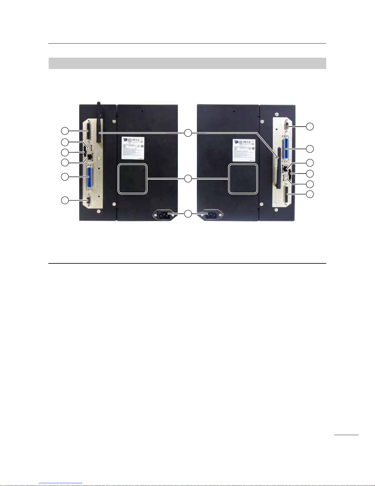
1.2.2
Rear View
6
8
10
9
7
11
12
13
14
10
9
11
12
13
14
S84-ex/S86-ex
(Americas: Opposite/Left Hand,
Europe/Asia: Right Hand) printer
S84-ex/S86-ex
(Americas: Standard/Right Hand,
Europe/Asia: Left Hand) printer
Wireless LAN (optional) antenna
To install the optional wireless LAN antenna.
Fan filter
To prevent dust from entering the printer.
AC input terminal
Supplies power to the printer through the
inserted power cord.
Before connecting, make sure that the AC
voltage of your region is in the range of AC 100
to 240 V, 50 to 60 Hz.
RS-232C connector
To connect the printer to the host computer
using the RS-232C serial interface.
IEEE1284 connector
To connect the printer to the host computer
using the IEEE1284 interface.
LAN connector
To connect the printer to the host computer
using the LAN interface.
SD CARD slot
To install an SD card for additional memory.
USB connector (Type B)
To connect the printer to the host computer
using the USB interface.
EXT connector (External signal
interface)
Interface connector for external signals.
Connect the optional applicator to this terminal.
1 Parts Identification
18
S84-ex/S86-ex Operator Manual
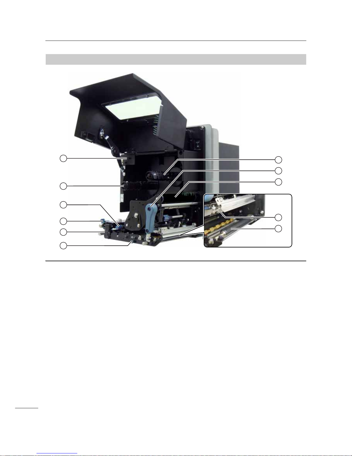
1.2.3
Internal View
15
16
23
22
25
21
17
18
19
20
24
USB connector (Type A)
For connecting to optional USB memory.
Ribbon supply spindle
Media sensor adjustment knob
Used to adjust the position of the media
sensor.
Media guide
Feed lock latch
Used to open the feed roller and the media
sensor assembly.
Pressure roller release tab
Used to release the pressure plate.
Ribbon rewind spindle
Head lock lever
Used to release the print head assembly.
Ribbon roller
Print head (Consumables)
The part to print on the media. Perform regular
maintenance.
Platen roller (Consumables)

1 Parts Identification
19
S84-ex/S86-ex Operator Manual
1.3
Parts on the Operator Panel
1.3.1
Operator Panel
2
3
5
4
1
6
7
8
Note: Remove the protective sheet from the operator panel before use.
LINE button
Toggle between online/offline mode.
LCD
FEED button
Feed a piece of media when the printer is in
offline mode.
LED indicator
FUNCTION button
Operates the set function when the printer is in
normal mode.
Returns to the setting mode menu from the
setting screens.
ENTER button
Enter the setting mode menu when the printer
is in offline mode.
Confirm the selected item or the setting value
when the printer is in setting mode.
CANCEL button
Go to the CANCEL PRINT JOB screen when
the printer is in offline mode.
Returns to the previous setting screen when
the printer is in setting mode.
/ / / Arrow buttons
Navigate the selection or set numbers in the
screen menu.
Press the button to adjust the buzzer
volume when the printer is in normal mode.
Press the and buttons for one second
to enter the adjustment mode when the printer
is in normal mode.
1 Parts Identification
20
S84-ex/S86-ex Operator Manual
1.3.2
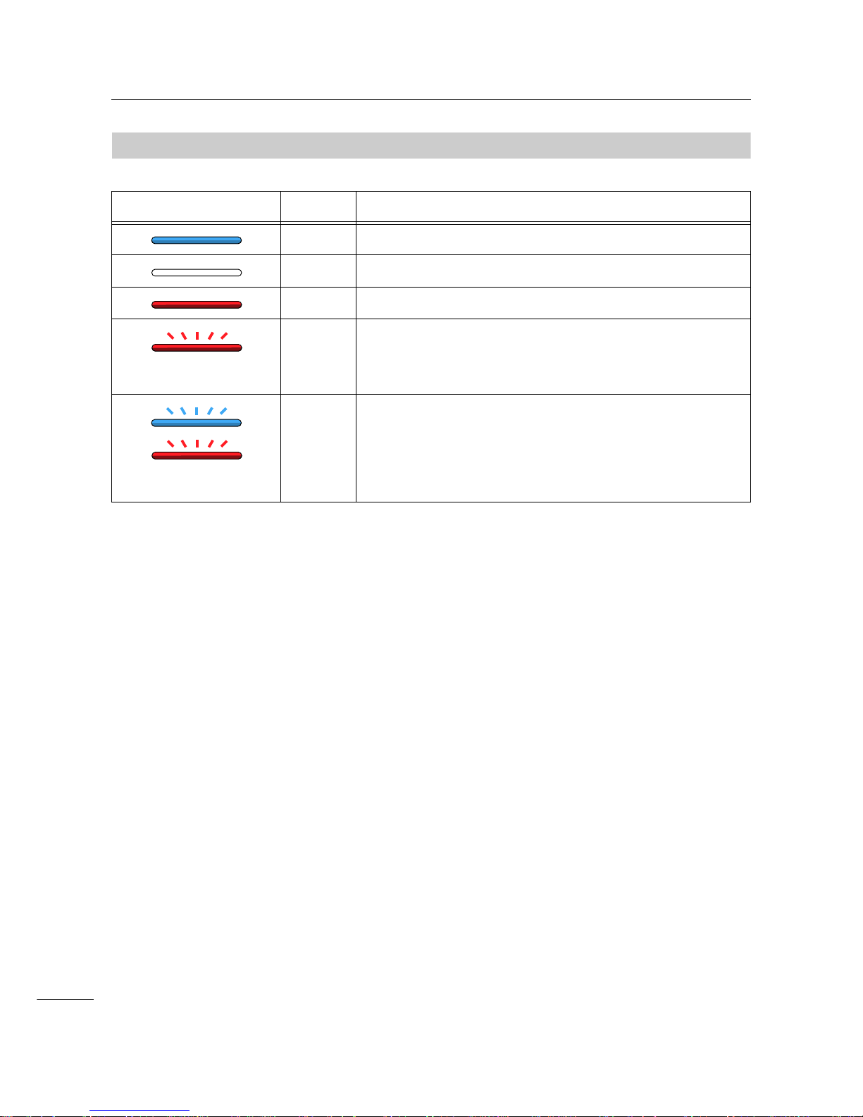
LED Indicator
LED Indicator Color Description
Blue Power on or online mode
(Light off) Power off or offline mode
Red Printer error (For example, when a machine error is detected)
Flashes at intervals of two
seconds.
Red Printer error (For example, when the ribbon runs out)
Alternately flashes blue
and red.
Blue and
red
Printer error (For example, when a communication error has
occurred)

21
S84-ex/S86-ex Operator Manual
2.1
Installation Precautions
Install this printer in a location as follows:
• A location that is horizontal and stable.
When you install the printer onto a support structure/applicator, the complete assembly must be sturdy
and stable.
Attach the support structure firmly to the floor or on production machinery.
• A location that has sufficient space for operating the printer.
Install the printer so that the media dispenser side is within the designated distance and height relative
to the applicator.
Install the media supply dispensers with an operational distance to the printer’s input side.
Do not install this printer in a location as follows. Doing so could cause the printer to malfunction.
• A location that is subject to vibration.
• A location with high temperature and humidity.
• A dusty location.
• A location exposed to direct sunlight.
• A location with a lot of electrical noise.
• A location with a large fluctuation in power.
2
Installing the Printer
2 Installing the Printer
22
S84-ex/S86-ex Operator Manual
2.2
Installation Space
For easy operation and correct airflow, make sure that there is sufficient space around the printer .
The illustrations in this section show the printer from different angles, providing dimensions and spatial
requirements.
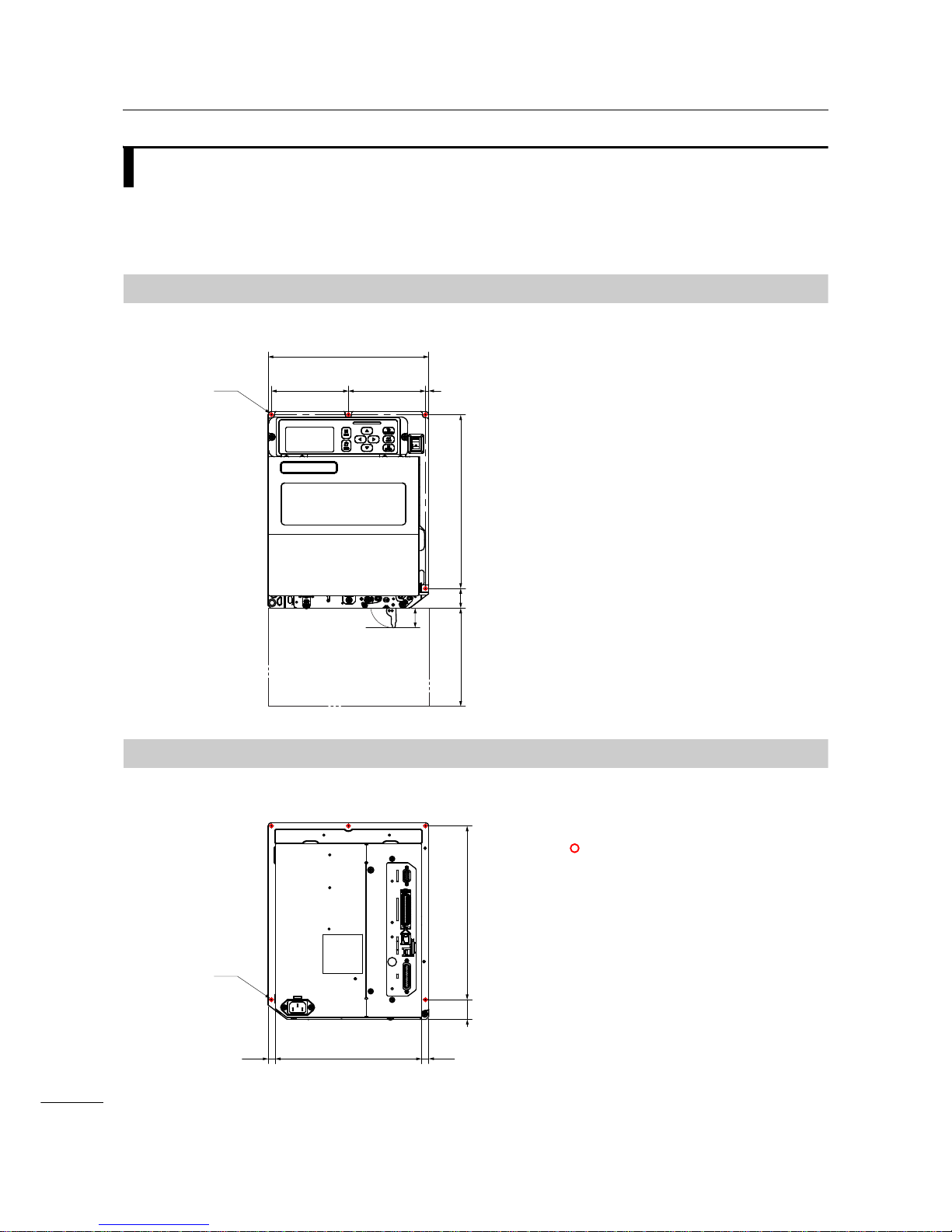
2.2.1
Front View (S84-ex/S86-ex printer)
2.2.2
Rear View (S84-ex/S86-ex printer)
245 mm (9.6”)
117.5 mm
(4.6”)
117.5 mm
(4.6”)
5 mm (0.2”)
265 mm (10.4”)
30 mm
(1.2”)
150 mm (5.9”)
Ø 5 mm (0.2”)
5 positions
36 mm
(1.4”)
Americas: Standard/Right Hand
Europe/Asia: Left Hand
223 mm (8.8”)
11 mm (0.4”)
11 mm (0.4”)
265 mm (10.4”)
Ø 5 mm (0.2”)
5 positions
30 mm
(1.2”)
indicates five positions of
bores for installing the printer
to a support structure.
Americas: Standard/Right Hand
Europe/Asia: Left Hand
2 Installing the Printer
23
S84-ex/S86-ex Operator Manual
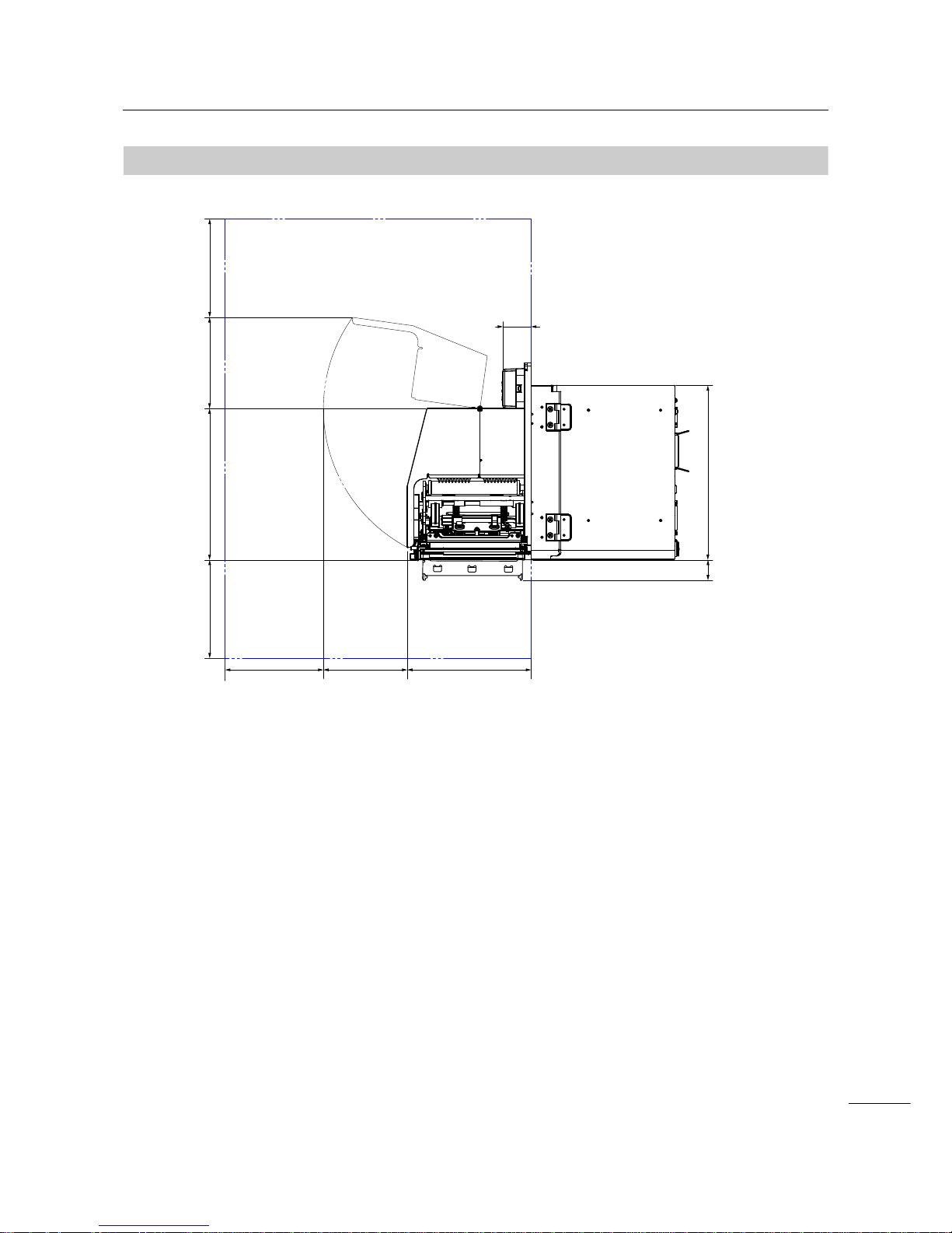
2.2.3
Media Dispensed View (S84-ex printer)
150 mm (5.9”) 150 mm (5.9”)
150 mm (5.9”)
231 mm (9.1”)
189 mm (7.4”)
266 mm (10.5”)
43 mm (1.7”)
131 mm (5.15”)
168 mm (6.6”)
Americas: Standard/Right Hand
Europe/Asia: Left Hand
36 mm
(1.4”)

2 Installing the Printer
24
S84-ex/S86-ex Operator Manual
2.2.4
Top View (S84-ex printer)
230 mm (9.1”)
219 mm (8.6”)189 mm (7.4”)
10 mm (0.4”)
51 mm
(2”)
150 mm (5.9”)
223 mm (8.8”) 174 mm (6.85”)174 mm (6.85”) 150 mm (5.9”)150 mm (5.9”)
Americas: Standard/Right Hand
Europe/Asia: Left Hand

2 Installing the Printer
25
S84-ex/S86-ex Operator Manual
2.2.5
Media Dispensed View (S86-ex printer)
150 mm (5.9”) 150 mm (5.9”)
150 mm (5.9”)
231 mm (9.1”)
243 mm (9.6”)
266 mm (10.5”)
43 mm (1.7”)
131 mm (5.15”)
168 mm (6.6”)
Americas: Standard/Right Hand
Europe/Asia: Left Hand
36 mm
(1.4”)

2 Installing the Printer
26
S84-ex/S86-ex Operator Manual
2.2.6
Top View (S86-ex printer)
51 mm
(2”)
230 mm (9.1”)
150 mm (5.9”)
223 mm (8.8”) 174 mm (6.85”)174 mm (6.85”) 150 mm (5.9”)150 mm (5.9”)
219 mm (8.6”)243 mm (9.6”)
10 mm (0.4”)
Americas: Standard/Right Hand
Europe/Asia: Left Hand

2 Installing the Printer
27
S84-ex/S86-ex Operator Manual
2.3
Installing the Printer onto a Support
Structure/Applicator
This printer must be installed onto a support structure/applicator for correct operation.
The printer has five bores on the center frame for installing to a support structure.
Attach five bolts to the five bores on the center frame to install the printer onto the support structure.
WARNING
Make sure that you use the designated bolts that can ac com m o da te the weigh t of the pr int er.
If you do not install the printer correctly, it could fall out of the support structure. This may cause injury.
The picture below shows the installation of the printer onto the support structure.
Note
This picture is for an instructional display purpose only and is not to be interpreted as a precise example.

2 Installing the Printer
28
S84-ex/S86-ex Operator Manual
2.4
Checking the Bundled Accessories
After unpacking the printer, make sure that you have all the bundled accessories. If there are missing
items, contact the SATO reseller where you purchased the printer.
Note
Keep the packaging box and the cushioning material after installing the printer. You can pack the printer with
this packaging box for shipment when requesting for repairs.
User documents
(Quick guide, Warranty, etc.)
Ribbon core
* The shape of power plug varies depending on the region in which it was purchased.
14pin conversion cable
AC power cord*

2 Installing the Printer
29
S84-ex/S86-ex Operator Manual
2.5
Connecting the Interface Cable
The connection of the interface cable is explained as follows:
2.5.1
Available Interfaces
This printer supports the following interfaces.
Furthermore, a printer connected with multiple interface cables can continue to operate when receiving
data.
*You cannot receive data from more than one interface at a time.
*You cannot use the USB interface when you have installed the optional wireless LAN.
•USB
•LAN
• RS-232C
• IEEE1284
• Bluetooth
• Wireless LAN (WLAN)
• External signal (EXT)
Note
The wireless LAN interface and Bluetooth interface are optional.
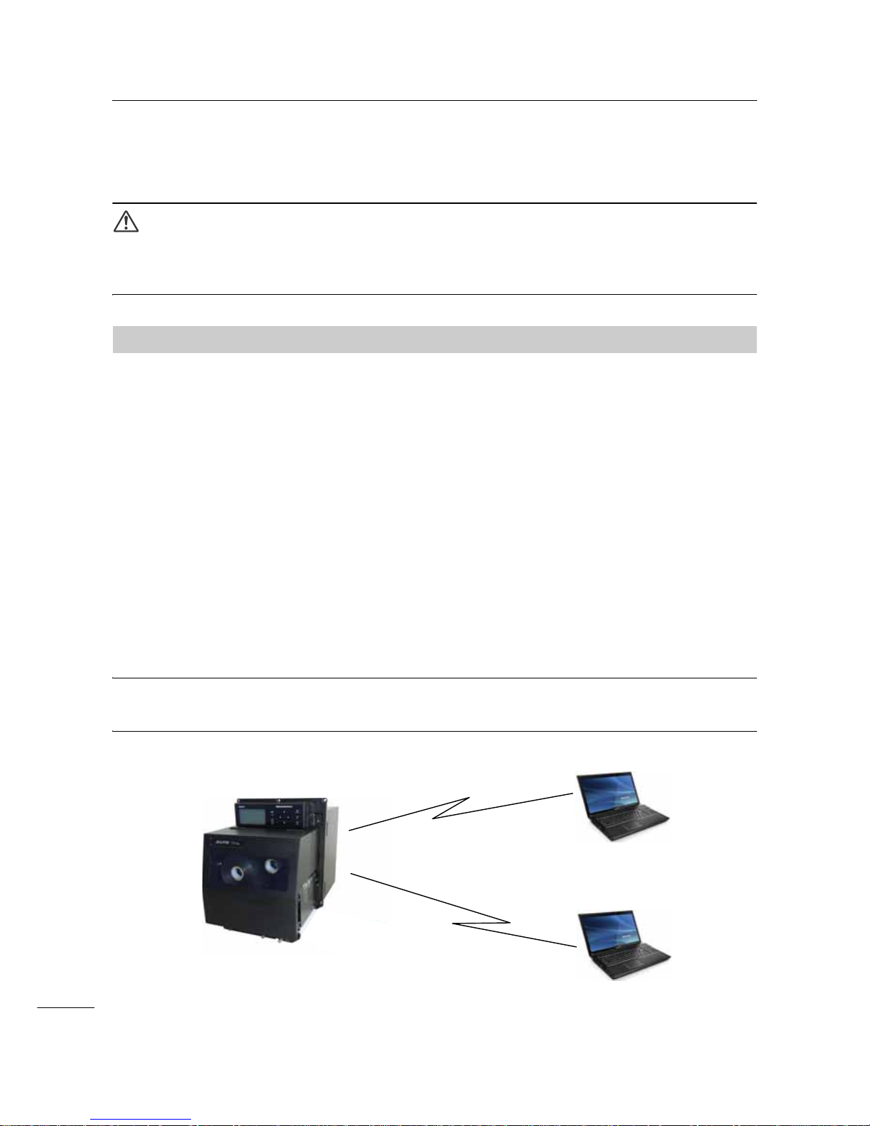
2.5.2
Interface Connections
1 Make sure that the printer, host computer and applicator are powered off.
Set the power switch of the printer to the “O” position.
2 Connect the printer to a host computer with one or more of the available interface
connections.
Use a cable that is compatible with the standard of the interface board as stated in Section 7.12
Interface Specifications. Check the orientation of the connector before you make the connection.
Applicator
Host computer
2 Installing the Printer
30
S84-ex/S86-ex Operator Manual
3 Connect the applicator cable from the EXT connector of the printer to the applicator.
Use a cable that is compatible with the standard of the interface board as stated in Section 7.12
Interface Specifications. Check the orientation of the connector before you make the connection.
CAUTION
Do not connect or disconnect the interface cables (or use a switch box) with power supplied to either the
printer or computer. This action may cause damage to the interface circuitry in the printer or computer. The
warranty does not cover such damages.
2.5.3
Interface Settings
You can set the various interface settings of the printer through the interface mode menu. For details,
refer to Section 4.2.10 Interface Mode.
In interface mode, you need to configure both the data port and the sub port. An overview of each port is
shown below.
Data port
When the interface is set to the data port, it can receive various SBPL commands and receive print data
from the host computer.
Data port selection: USB, LAN, RS-232C, IEEE1284, Bluetooth, WLAN (Wireless LAN)
The optional Bluetooth and optional wireless LAN are available when yo u have installed them.
* You cannot select the interface that has already been set for the SUB PORT.
Sub port
This port is for monitoring the printer status.
Sub port selection: NONE, USB, LAN, RS-232C, IEEE1284, Bluetooth, WLAN (Wireless LAN)
The optional Bluetooth and optional wireless LAN are available when yo u have installed them.
* You cannot select the interface that has already been set for the DATA PORT.
Note
The main port and sub port cannot simultaneously use the same interface.
Sub port
- Printer status
Data port
- SBPL command (Print data)
- Printer status
2 Installing the Printer
31
S84-ex/S86-ex Operator Manual
2.5.4
Interface Combination
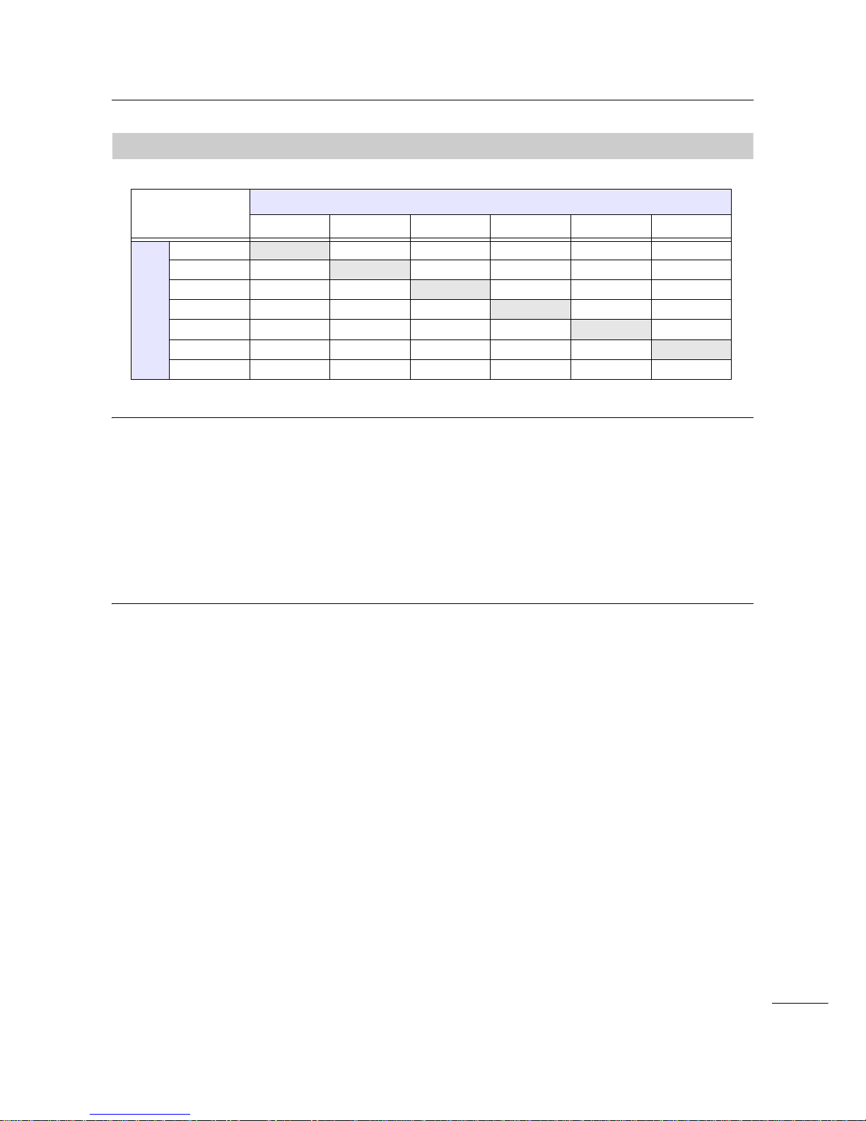
The interface combinations that can be used for the data port and the sub port are as follows.
[o: configurable, x: not configurable]
Note
• The optional Bluetooth and optional wireless LAN are available when you have installed them.
• Do not select the same interface for the data port and sub port.
• When you have installed the optional wireless LAN, you cannot use the USB interface. The optional
wireless LAN is connected to the printer through the USB.
• The sub port cannot be used when you have set ENABLE in the INTERFACE AUTO SELECT screen.
• When WLAN is configured for the data port or the sub port, but the printer is powered on without the
wireless LAN adapter, the configured interface setting is changed from WLAN to USB. When USB is
configured as the data port or the sub port, but the wireless LAN adapter is connected, the configured
interface setting is changed from USB to WLAN.
Data Port
USB LAN RS-232C IEEE1284 Bluetooth WLAN
Sub Port
USB xoooox
LAN o
xoooo
RS-232C o o
xooo
IEEE1284 o o o
xoo
Bluetooth o o o o
xo
WLAN x o o o o
x
NONEoooooo
2 Installing the Printer
32
S84-ex/S86-ex Operator Manual
2.6
Connecting the Power Cord
WARNING
• Do not touch the power switch, connect or disconnect the power cord while your hands are wet. Doing so
could cause an electric shock.
• Always connect the ground wire to a ground terminal. Electric shock could occur if you do not.
Note
• The attached power cord is designed exclusively for this printer.
• Do not use the attached power cord with other devices.
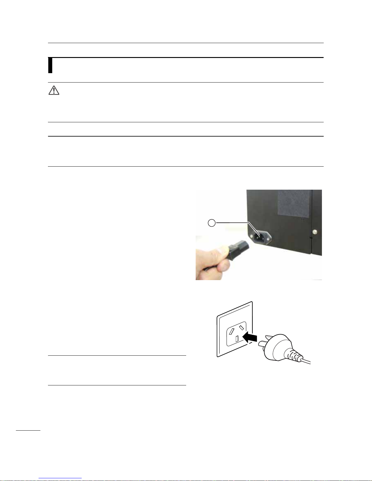
1 Connect the power cord to the AC input
terminal at the rear of the printer.
Take note of the orientation of the connector.
Secure the printer with one hand, and insert the
connector tightly.
2 Insert the power plug into an AC outlet.
Make sure that the AC voltage of your region is in
the range of AC 100-240 V, 50-60 Hz. If your
local voltage is not in the stated range, contact
your SATO reseller or technical support center.
*The shape of the power plug varies depending
on the region in which it was purchased.
Note
This product is also designed for IT power distribution
system with phase-to-phase voltage 230 V.
1
*

2 Installing the Printer
33
S84-ex/S86-ex Operator Manual
2.7
Power On/Off the Printer
WARNING
Do not touch the power switch, connect or disconnect the power cord while your hands are wet. Doing so
could cause an electric shock.
2.7.1
Power On the Printer
1 Press the power switch on the operator
panel to “I” position.
2 ONLINE shows on the screen and the
LED lights blue.
2.7.2
Power Off the Printer
1 Make sure that the printer is in offline
mode before you power off.
If ONLINE shows on the screen, press the
LINE button to change to offline mode.
2 Press the power switch on the operator
panel to “O” position.
2 Installing the Printer
34
S84-ex/S86-ex Operator Manual
2.8
Installing Optional Memory Storage
The optional SD card or USB memory can be used for uploading and downloading data (print format,
graphics, extended characters) registered in the printer and printer firmware.
Contact your SATO reseller or service center for the recommended SD card or USB memory.
2.8.1
Installing the Optional SD Card
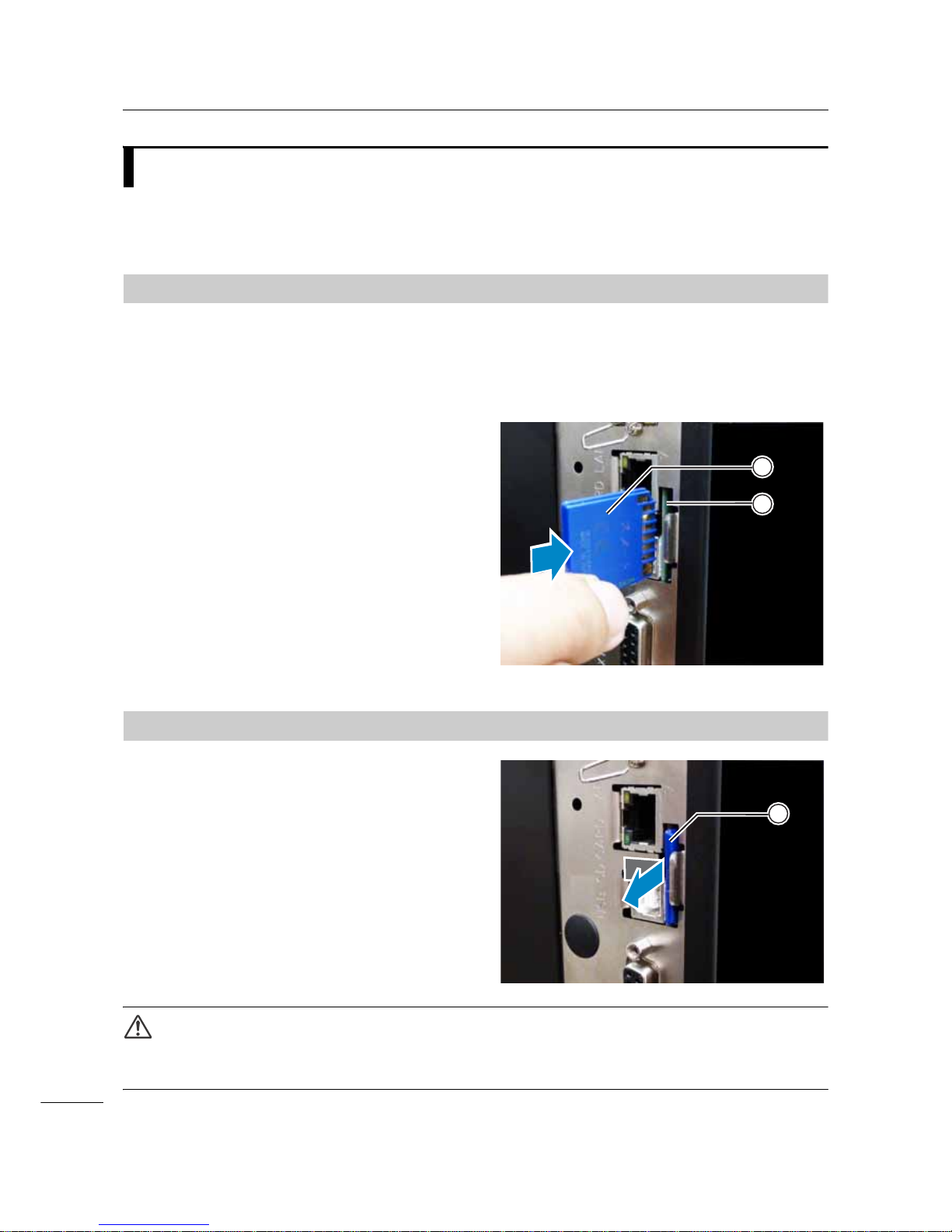
You can install an optional SD card into the SD card slot located on the rear of the printer.
When using the SD card for the first time, format the SD card in the memory card mode. Refer to
Section 4.2.11 Memory Mode for details.
1 Power off the printer.
2 Insert the optional SD card into the SD
card slot with the orientation the same
as shown in the picture.
Contact your SATO reseller for the recommended
SD card.
3 To seat the SD card in the SD card slot,
push it in until it makes a slight clicking
sound and is almost completely inside the
printer.
When seated and ready to operate, only a very
small portion protrudes, approximately 3.18 mm
(0.125”).
2.8.2
Removing the Optional SD Card
1 Power off the printer.
2 Press the card edge slightly to release the
SD card from the SD card slot. The SD
card slot will immediately release the SD
card .
CAUTION
Do not remove the SD card while the printer is accessing the data in the SD card. Doing so may result in data
corruption.
2
1
1
2 Installing the Printer
35
S84-ex/S86-ex Operator Manual
2.8.3
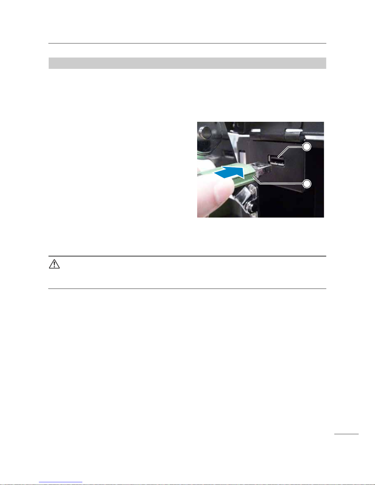
Installing the Optional USB Memory
When using the USB memory for the first time, format the USB memory in the memory card mode. Refer
to Section 4.2.11 Memory Mode for details.
1 Power off the printer.
2 Open the top cover.
3 Insert the optional USB memory into the
USB connector (Series A plug, 2.0
High-speed) on the front of the printer.
Contact your SATO reseller for the recommended
USB memory.
4 Close the top cover.
To remove the USB memory from the printer
Power off the printer before removing the USB memory.
CAUTION
Do not remove the USB memory while the printer is accessing the data in the USB memory. Doing so may
result in data corruption.
1
2

2 Installing the Printer
36
S84-ex/S86-ex Operator Manual
This page is intentionally left blank.

37
S84-ex/S86-ex Operator Manual
+
This printer supports two types of print methods, namely thermal transfer and direct thermal. Thermal
transfer is a print method that transfers the ink of the ribbon to the media using the heat of the print head.
Direct thermal is a print method that creates the image on direct thermal media using the heat of the print
head. Ribbon is not necessary if you are using direct thermal media.
3.1
Checking the Ink Side of the Ribbon
There are two wind directions for the ribbon. Face-out means the ink is on the outer side and Face-in
means the ink is on the inner side. This printer supports both wind directions. You can examine the ink
side of the ribbon using the following procedure:
1 Place the outer side of the ribbon onto
the media (touching).
2 Scratch the inner side of the ribbon with
your fingernail or a pointed object.
3 If there is a mark on the media, the ink is
coated on the outer side of the ribbon.
3
Loading the Ribbon and
Media
The ink is coated
on the inner side.
(Face-in ribbon)
The ink is coated
on the outer side.
(Face-out ribbon)
3 Loading the Ribbon and Media
38
S84-ex/S86-ex Operator Manual
3.2
Loading the Ribbon
Use genuine media and ribbons for the printer, for optimum print quality.
CAUTIONS
• The print head and its surroundings are hot after printing. Be careful not to touch it, to avoid being burned.
• Touching the edge of the print head with your bare hand could cause injury.
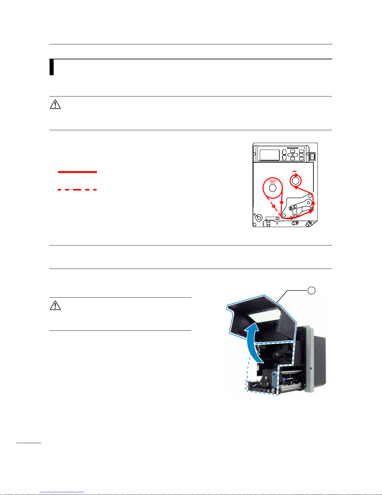
The routing path of the ribbon is shown in the right
picture.
Note
You can also refer to the sticker located on the inner side of the top cover.
1 Open the top cover .
CAUTION
Open the top cover fully to prevent accidental drop of
the cover.
Face-in ribbon
Face-out ribbon
1

3 Loading the Ribbon and Media
39
S84-ex/S86-ex Operator Manual
2 Turn the head lock lever clockwise to
unlock the print head.
3 Load the ribbon onto the ribbon supply
spindle .
While taking note of the wind direction, insert the
ribbon all the way in.
Make sure that the ink side of the ribbon is facing
down when passing it below the print head.
4 Load an empty ribbon core onto the
ribbon rewind spindle .
Insert the core all the way in.
2
4
6
5
3

3 Loading the Ribbon and Media
40
S84-ex/S86-ex Operator Manual
5 From the ribbon supply spindle , pass
the ribbon below the print head and to
the ribbon rewind spindle .
6 Wind the ribbon clockwise around the
empty ribbon core on the ribbon
rewind spindle . Attach the free end of
the ribbon to the core with adhesive tape
.
7 Turn the ribbon rewind spindle
clockwise for several rounds, to wind the
ribbon.
8 If the media is already loaded, turn the
head lock lever counterclockwise to
lock the print head.
If the media is not loaded, continue with Section 3.5
Loading Media.
9 Close the top cover.
4
6
7
8
6
2

3 Loading the Ribbon and Media
41
S84-ex/S86-ex Operator Manual
3.3
Removing the Ribbon
1 Open the top cover.
2 Turn the head lock lever clockwise to unlock the print head.
3 Pull to remove the used ribbon from the
ribbon rewind spindle .
4 Pull to remove the empty core from the
ribbon supply spindle .
You can use this empty core again when you load a
new ribbon roll. Load this empty core onto the
ribbon rewind spindle.
1
2

3 Loading the Ribbon and Media
42
S84-ex/S86-ex Operator Manual
3.4
Usable Media
This printer can print on two types of media; media roll and fan-fold media. The printer uses sensors to
detect I-marks or Gaps on the media in order to precisely print the content.
3.4.1
Adjusting the Position of the Media Sensor
Nonstandard media are media with printing on the reverse side, or media with special shapes. When
using nonstandard media, make sure that the media sensor position is aligned with the I-mark or gap of
the media.
The I-mark sensor of the printer has a fixed position of 5 mm (0.2”) measured from the printer’s center
frame.
The position of the gap sensor is adjustable. You can adjust the gap sensor position in the following
range.
S84-ex printer: 5 mm to 66 mm (0.2” to 2.6”) measured from the printer’s center frame.
S86-ex printer: 5 mm to 81 mm (0.2” to 3.2”) measured from the printer’s center frame.
1 Open the top cover.
2 Turn the media sensor adjustment knob
clockwise or counterclockwise to adjust
the gap sensor position.
The green indicator on top of the media sensor
assembly shows the position of the gap sensor.
14 mm
(0.55”)
1.5 mm (0.06”)
I- mar k journal paper/linerless labelGap labelI-mark label
3 mm (0.12”)
3 mm
(0.12”)
3 mm
(0.12”)
1.5 mm (0.06”)
14 mm
(0.55”)
3 mm
(0.12”)
Media feed
direction
Media feed
direction
Media feed
direction
1
2

3 Loading the Ribbon and Media
43
S84-ex/S86-ex Operator Manual
3.5
Loading Media
Use genuine media and ribbons for the printer, for optimum print quality.
CAUTIONS
• The print head and its surroundings are hot after printing. Be careful not to touch it, to avoid being burned.
• Touching the edge of the print head with your bare hand could cause injury.
3.5.1
Loading Label with Dispenser
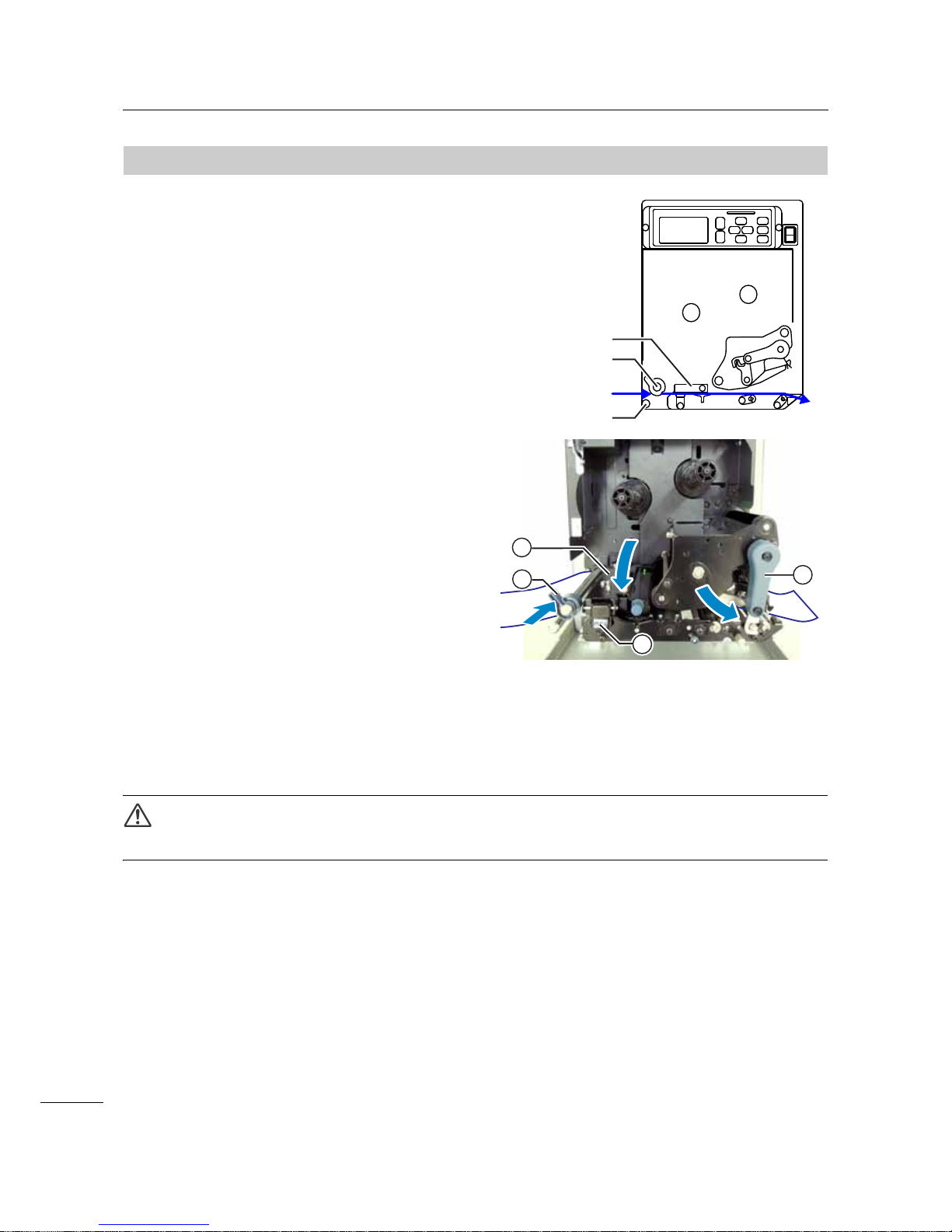
This section describes the procedure to dispense the label and eject the liner out of the printer. The
routing path of the label is shown below. When loading the media, make sure that the print side is facing
up.
1 Open the top cover.
CAUTION
Open the top cover fully to prevent accidental drop of
the cover.
Label
Platen roller
Pressure
roller
Liner
/DEHO
/LQHU
Feed roller and
media sensor
assembly
Media shaft
Media shaft
Label

3 Loading the Ribbon and Media
44
S84-ex/S86-ex Operator Manual
2 Turn the head lock lever clockwise to
unlock the print head.
3 Pull the feed lock latch to unlock the
feed roller and media sensor assembly
.
The feed roller and media sensor assembly will flip
open.
4 Pull the media guide away from the
printer.
5 Pass the media between the media shaft
, below the feed roller and media
sensor assembly , and the print head
assembly and extend it out the
discharge outlet.
Make sure that the end of the media extends out the
discharge outlet.
6 Push the media until the innermost edge of
the media lightly touches the printer center
frame.
7 Pull the label out from the discharge outlet.
Remove about 30 cm (11.8”) of labels
from the liner .
1
4
2
3
5
3 6
8
7

3 Loading the Ribbon and Media
45
S84-ex/S86-ex Operator Manual
8 Push the pressure roller release tab up
to release the pressure roller plate .
9 Pass the liner through the gap of the
pressure roller plate .
10
Push the center of the pressure roller
plate to latch it in place.
11
Turn the head lock lever counterclockwise
to lock the print head.
12
Close the top cover.
13
After loading the media and ribbon, perform
a test print to make sure that the media is
loaded correctly.
Refer to the Section 4.2.16 Test Print Mode for
details on how to perform a test print.
CAUTION
• When closing the top cover, be careful not to pinch your fingers.
9
10
10
8
8
10
3 Loading the Ribbon and Media
46
S84-ex/S86-ex Operator Manual
3.5.2
Loading Media without Using Dispenser
This section describes the procedure to just load the
media without using the dispenser. The routing path
of the media is shown in the right picture.
When loading the media, make sure that the print side
is facing up.
1 Refer to steps 1 through 6 of Section
3.5.1 Loading Label with Dispenser to
load the media.
2 Turn the head lock lever
counterclockwise to lock the print head.
3 Press the feed roller and media sensor
assembly down until the feed lock
latch is locked.
4 Push the media guide lightly against the
outermost edge of the media.
5 Close the top cover.
6 After loading the media and ribbon, perform
a test print to make sure that the media is
loaded correctly.
Refer to the Section 4.2.16 Test Print Mode for
details on how to perform a test print.
CAUTION
• When closing the top cover, be careful not to pinch your fingers.
Feed roller and
media sensor
assembly
Media shaft
Media shaft
Media
2
3
1
4
47
S84-ex/S86-ex Operator Manual
4.1
Display and Operation
The display of the printer varies depending on the following modes:
• Normal mode: refer to Section 4.1.1 Normal Mode Display and Icons.
• Setting mode menu: refer to Section 4.1.2 Setting Mode Menu and Icons.
• Error display: refer to Section 4.1.3 Error Display and Icons.
• Setting display: refer to Section 4.1.4 Setting Display.
4.1.1
Normal Mode Display and Icons
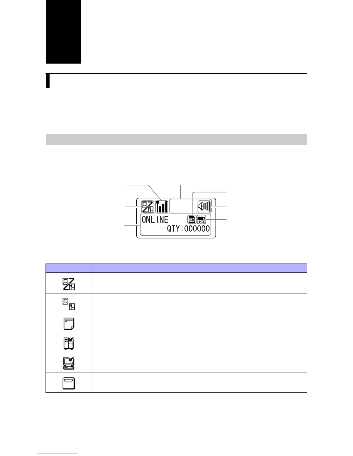
In normal mode, the screen shows the following printer status.
• Printer mode
4
Operation and
Configuration
Icon Description
Shows when the printer is in online mode.
Shows when the printer is in offline mode.
Shows when the printer is in test print mode and hex dump print m od e.
Shows when the printer is in download mode.
Shows when the printer is in upload mode.
Shows when the printer is in memory mode.
Printer mode icon
Trace mode status icon,
WLAN field intensity
status icon or Bluetooth
connection status icon
Message display
SD card icon
USB memory icon
Buzzer volume icon
Warning icons
4 Operation and Configuration
48
S84-ex/S86-ex Operator Manual
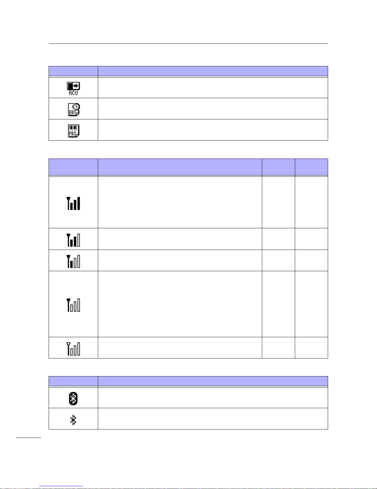
• Trace mode status
• WLAN field intensity status
• Bluetooth connection status
Icon Description
Shows after receiving any data while trace mode is ENABLE.
Shows after receiving ESC (1BH) A while trace mode is ENABLE.
Shows after print operation while trace mode is ENABLE.
Icon Description
Infrastructure Mode
Ad Hoc
Mode
The meaning of this icon differs depending on the wireless LAN
mode.
In Infrastructure mode
Shows when the field intensity is more than level 3 and the
printer is connected to an access point.
In Ad Hoc mode
Always shows when the printer is connected.
OO
Shows when the field intensity is between levels 2 and 3, and
the printer is connected to an access point.
O Not used
Shows when the field intensity is between levels 1 and 2, and
the printer is connected to an access point.
O Not used
The meaning of this icon differs depending on the wireless LAN
mode.
In Infrastructure mode
Shows when the field intensity is less than level 1 and the
printer is connected to an access point.
However, it may be possible to communicate depending on the
environment.
In Ad Hoc mode
Always shows when the printer is not connected.
OO
Shows when the printer is not connected to an access point. O Not used
Icon Description
Shows when Bluetooth is connected.
Shows when Bluetooth is disconnected.
4 Operation and Configuration
49
S84-ex/S86-ex Operator Manual
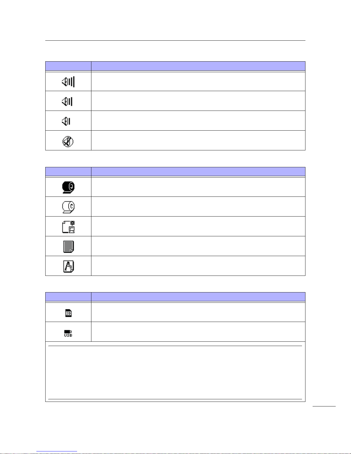
•Buzzer volume
• Warning Icons
• Memory card status
Icon Description
Shows when the volume is level 3 (Loud).
Shows when the volume is level 2 (Medium).
Shows when the volume is level 1 (Low).
Shows when the volume is level 0 (Mute).
Icon Description
Shows when a ribbon “near end” is detected.
Shows when a label “near end” is detected.
Shows when a command error is detected.
Shows when a receive buffer “near full” is detected.
Shows when print head damage is detected.
Icon Description
Shows when an SD card is inserted.
Shows when a USB memory is inserted.
Note
• These icons show only when the SD card or USB memory is connected.
• These icons do not show when the printer is in an error mode.
• These icons do not show when the trace mode is enabled.
• These icons do not show when the ESC+IM command (for specifying LCD display) is in use.
• These icon colors are inverted when the SD card or USB memory is being accessed.
4 Operation and Configuration
50
S84-ex/S86-ex Operator Manual
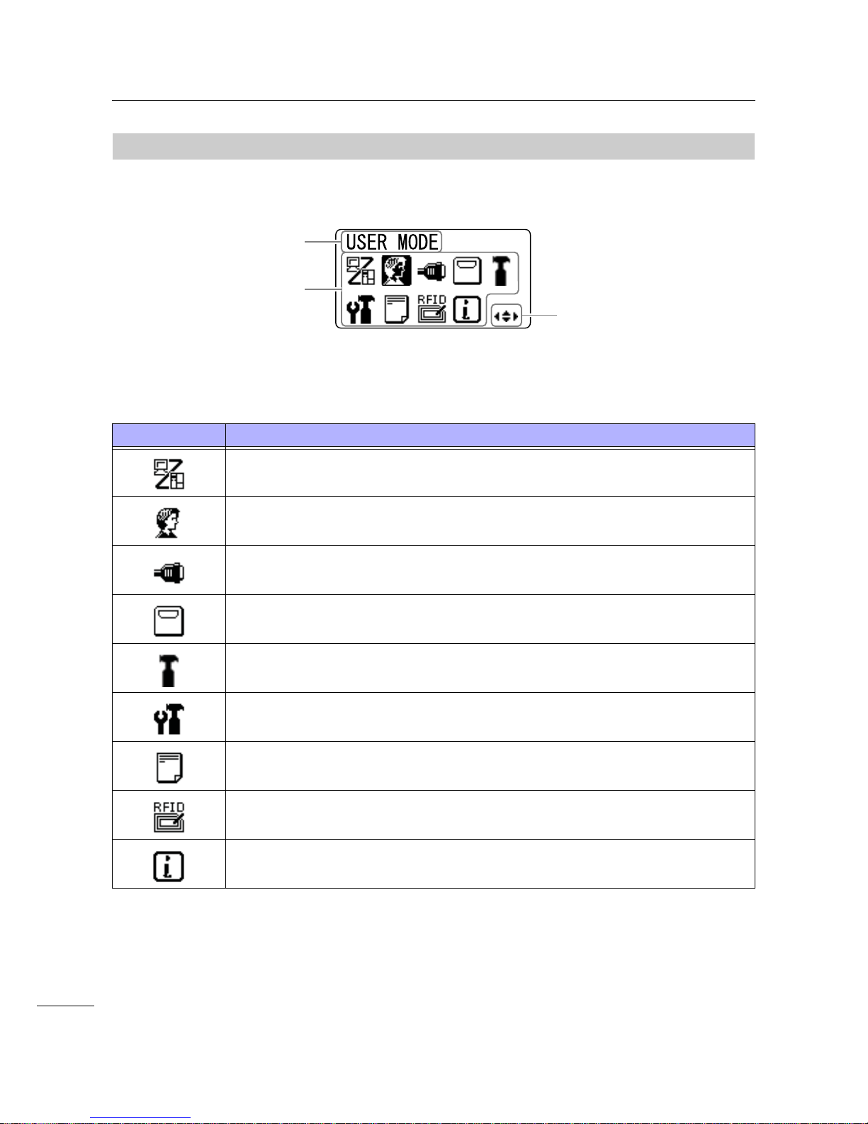
4.1.2
Setting Mode Menu and Icons
In the setting mode menu, the screen is sho wn as follows.
Refer to Section 4.2.8 Setting Mode Menu for more details.
• Setting Mode
Icon Description
The printer enters the normal mode.
The printer enters the user mode.
The printer enters the interface mode.
The printer enters the memory mode.
The printer enters the service mode.
The printer enters the advanced mode.
The printer enters the hex dump print mode.
The printer enters the RFID mode.
* Shows only if you have installed the optional RFID kit and enabled the RFID mode.
The printer enters the printer information mode.
Setting mode icons
When an icon is
selected, its color is
inverted.
Selected setting mode
Valid arrow buttons
for selection.

4 Operation and Configuration
51
S84-ex/S86-ex Operator Manual
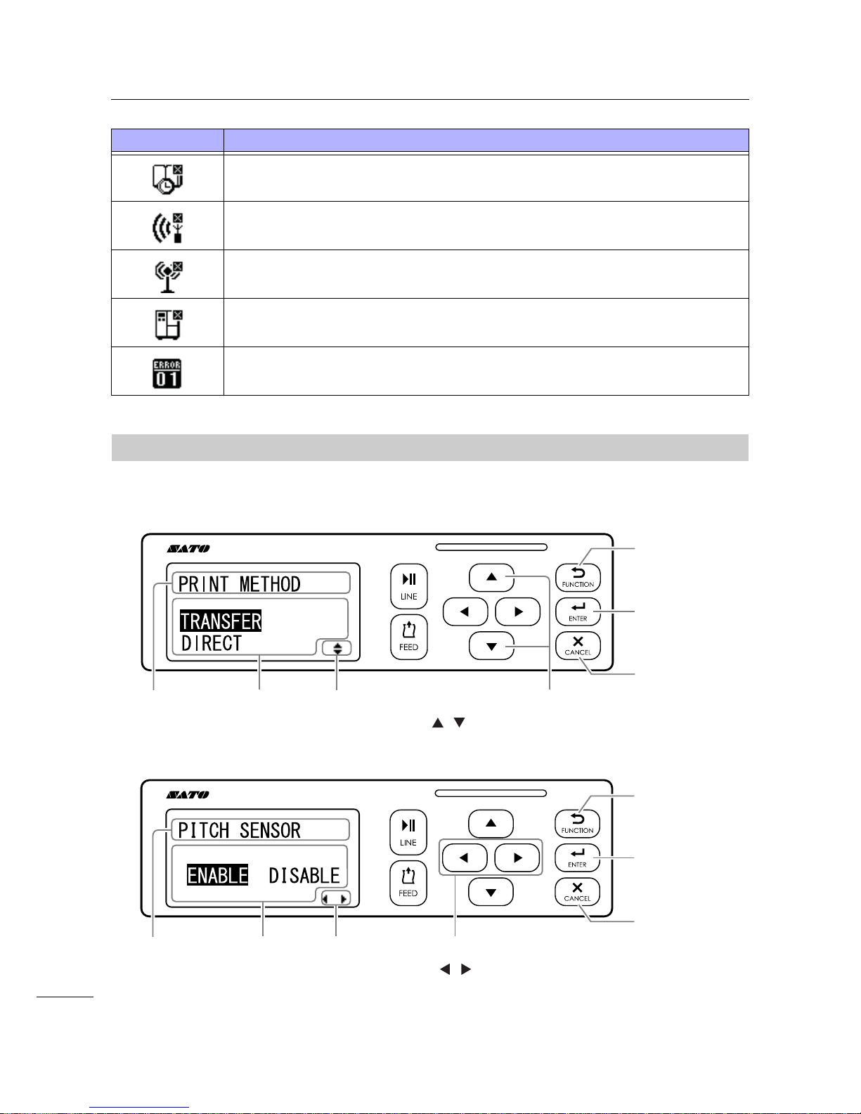
4.1.3
Error Display and Icons
When a printer error occurs, the screen shows the following error messages and icons.
• Error Icon
Icon Description
Label end or media end is detected.
Ribbon end is detected.
Sensor error is detected.
Print head is unlocked.
Filament disconnection of the print head is detected.
Communication error is detected.
Receive buffer over is detected.
Item No. error or BCC error is detected.
Memory card is not accessible or there is no free space in the memory card.
Writing to the ROM failed or kanji data error is detected.
Error message
Countermeasure
message
Alternates every three seconds
Error number icon
Error icon
Shows the valid arrow
button to switch the screen.
4 Operation and Configuration
52
S84-ex/S86-ex Operator Manual
4.1.4
Setting Display
In various setting mode, the setting display is shown as follows. This section also describes the functions
of the buttons in setting mode.
• Selecting an item
Calendar error is detected.
Writing information to the RFID tag failed.
Wireless LAN setting error is detected.
Any printer error other than above is detected.
Error number according to the errors.
Icon Description
Select an item using the
/ buttons.
Returns to the
previous screen
without saving
the setting.
Save the setting
and go to the
next screen.
Go to the setting
mode menu
without saving
the setting.
Setting contents
display
Setting item
display
Select an item using the
/ buttons.
Valid arrow
buttons display
Valid arrow
buttons display
Setting contents
display
Setting item
display
Returns to the
previous screen
without saving
the setting.
Save the setting
and go to the
next screen.
Go to the setting
mode menu
without saving
the setting.
4 Operation and Configuration
53
S84-ex/S86-ex Operator Manual
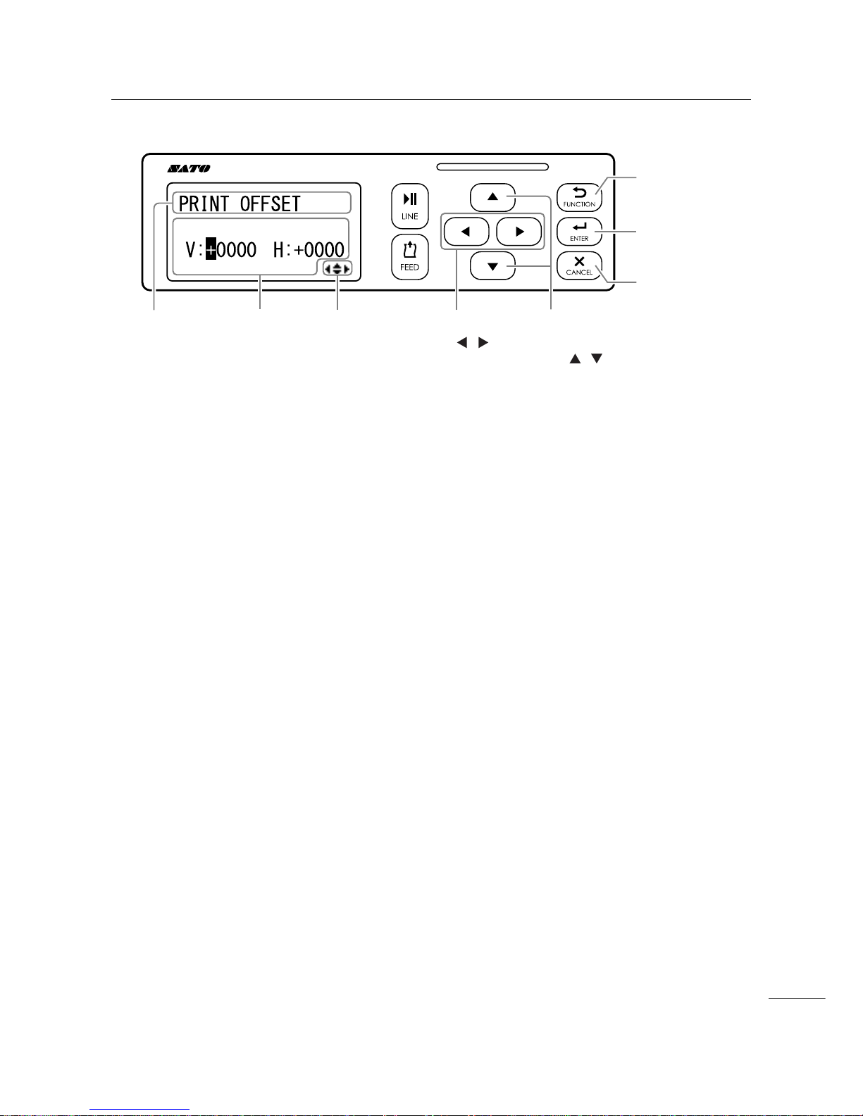
• Setting values
Setting contents
display
Setting item
display
Valid arrow
buttons
display
Move the cursor
using the /
buttons.
Change the value of
the highlighted cursor
using the /
buttons.
Save the value
and go to the
next screen.
Go to the setting
mode menu
without saving
the setting.
Returns to the
previous screen
without saving
the setting.

4 Operation and Configuration
54
S84-ex/S86-ex Operator Manual
4.2
Operating Modes
The printer contains a variety of the following operating modes:
Click on the blue links below to go directly to the details of the selected operating mode.
• Online Mode/Pause Mode/Offline Mode
• Adjusting the Display Brightness
• Adjusting the Buzzer Volume
• Canceling the Print Job
• Adjustment Mode
• Work Shift Setting Mode
• Simple Standalone Mode
• Setting Mode Menu:
•User Mode
•Interface Mode
•Memory Mode
•Service Mode
•Advanced Mode
•Hex Dump Mode
•Information Mode
• Test Print Mode
• Default Setting Mode
• Download Mode
• Upload Mode
• Hidden Setting Mode
• Wireless LAN Certificate Download Mode
• Site Survey Mode

4 Operation and Configuration
55
S84-ex/S86-ex Operator Manual
The flow chart provides a clear summary of all the modes and their access methods.
Power off
button
s
Online state
Power on
Offline state
User mode
Interface mode
Advanced mode
HEX dump
mode
More operations are shown on the next page.
button
button
Sound
adjustment mode
Work shift
setting mode
Memory card
mode
RFID user
mode
Information
mode
Service mode
Print pause request/
button
Simple
standalone mode
Adjustment
mode
Cancel print job
mode
button
button
(Press for 5 seconds)
button
(Press for 5
seconds)
button
buttons
+
button
button
button
button
button
button
button
button
button
s
button
s
button
s
button
s
button
s
button
s
button
s
* Shows only if you have
installed the optional RFID
kit and enabled RFID mode.
(Press for 1
second)
buttons
+
buttons
+
User Mode
Adjustment
Mode
Sound
Adjustment
Interface
Mode
Memory
Mode
Service Mode
Advanced
Mode
Hex Dump
Mode
Information
Mode
Work Shift
Setting Mode
Simple
Standalone
Mode
Canceling the
Print Job

4 Operation and Configuration
56
S84-ex/S86-ex Operator Manual
Power on
Power off
Test print mode
Power on
Default setting
mode
Download
mode
+
Power on
Upload
mode
+
Power on
+
+
Hidden setting
mode
+ + +
Power on
WLAN certificate
download mode
+ +
Power on
Site survey
mode
+ +
Power on
<(6
12
6,7(6859(<
67$57
Test Print
Mode
Default
Setting Mode
Download
Mode
Hidden
Setting Mode
Upload
Mode
Wireless LAN
Certificate
Download Mode
Site Survey
Mode

4 Operation and Configuration
57
S84-ex/S86-ex Operator Manual
4.2.1
Online Mode/Pause Mode/Offline Mode
In online mode, the printer is ready to receive print data from the host computer or other connected
devices and start the print job.
When you send a pause command during printing, the printer stops the print job and enters pause mode.
In offline mode, you can cancel the print job, feed the media or enter the setting mode menu.
Enters offline mode
and the print job is
stopped.
Changes to
settings mode.
Adjust the
display
brightness.
Adjust the
buzzer volume.
Enters adjustment mode.
Shows the remaining
print job.
Shows the remaining print job.
Resume the
print job.
Enters online
mode or pause
mode.
Feed a
piece of
media.
Adjust the
display
brightness.
Shows the remaining
print job.
Enters
adjustment
mode.
• Adjust the
buzzer volume.
• Press for more
than five seconds to enter
the simple
standalone
mode.
Cancel the print
job.
Enters the setting
mode menu.

4 Operation and Configuration
58
S84-ex/S86-ex Operator Manual
4.2.2
Adjusting the Display Brightness
In normal mode (online or offline), press the / buttons repeatedly to adjust the display brightness.
You can adjust the brightness in thirty-two steps (sixteen left and sixteen right).
The brightness changes one step for every press of the button or button.
4.2.3
Adjusting the Buzzer Volume
In normal mode (online or offline), press the button repeatedly to adjust the volume of the buzzer.
1 When the printer is in online or offline mode, press the button to show the current
buzzer volume of the printer.
The buzzer volume icon is shown on the top right corner of the screen.
2 Pressing the button will cycle through the volume level and the buzzer will beep
according to the volume.
button
button
button button
button
This illustration shows the screen images of
the volume adjustment in offline mode.

4 Operation and Configuration
59
S84-ex/S86-ex Operator Manual
4.2.4
Canceling the Print Job
Cancel the print job according to the following procedure:
1 Press the LINE button to change the
printer to offline mode.
2 Press the CANCEL button.
CANCEL PRINT JOB shows to confirm the
cancelation of the print job.
3 Press the / buttons to select YES and
press the ENTER button to confirm.
CURRENT and ALL show on the screen.
Note
• Be sure you want to cancel the print job before
selecting YES. The job cannot be recovered and will
have to be re-transmitted to the printer.
• Press the FUNCTION button or the CANCEL
button to exit the CANCEL PRINT JOB mode without
clearing the print data.
4 Press the / buttons to select
CURRENT or ALL.
• CURRENT: Cancel the current print job.
• ALL: Cancel all the print jobs in printer’s memory.
5 Press the ENTER button to confirm.
CANCEL PRINT JOB COMPLETED shows and
three beeps will sound. The printer will then enter
offline mode. The selected print jobs will be cleared
from memory.

4 Operation and Configuration
60
S84-ex/S86-ex Operator Manual
4.2.5
Adjustment Mode
The printer has a quick access to the adjustment mode for setting the print position, stop position and
print darkness. These adjustments are in conjunction with the configuration adjustments performed in
the user mode menu.
1 When the printer is in online or offline mode, press the and buttons for one second
to enter the adjustment mode. PITCH POSITION shows on the screen.
2 Press the / buttons to set the desired value and press the ENTER button to
save the setting and proceed to the next adjustment screen.
PITCH POSITION
Offset the print position in the vertical direction.
Set the offset value with '+' to move the print position opposite the feed
direction and value with '-' to move the print position in the feed direction.
The setting value is adjustable by 0.25 mm (0.01”) regardless of the print
resolution.
The setting range is from -3.75 mm (-0.15”) to +3.75 mm (+0.15”).
OFFSET POSITON
Correct the offset position.
Offset position refers to the dispense stop position.
Set the offset value with '+' to move the stop position opposite the feed
direction and value with '-' to move the stop position in the feed direction.
The setting value is adjustable by 0.25 mm (0.01”) regardless of the print
resolution.
The setting range is from -3.75 mm (-0.15”) to +3.75 mm (+0.15”).
Press the or
button
+ buttons (press for 1 second)
button
* Press the or button to set the value.
button
button

4 Operation and Configuration
61
S84-ex/S86-ex Operator Manual
3 After adjustment, press the FUNCTION button or the CANCEL button to exit the
adjustment mode. The printer enters offline mode.
Note
Pressing the FUNCTION button or the CANCEL button before pressing the ENTER button will not
save the adjustment.
4 Perform a test print after completing the adjustments to make sure that the settings are
correct.
Refer to Section 4.2.16 Test Print Mode for details.
DARKNESS
Fine tune the print darkness.
The setting range is from 00 to 99.
00 is the lightest and 99 is the darkest.
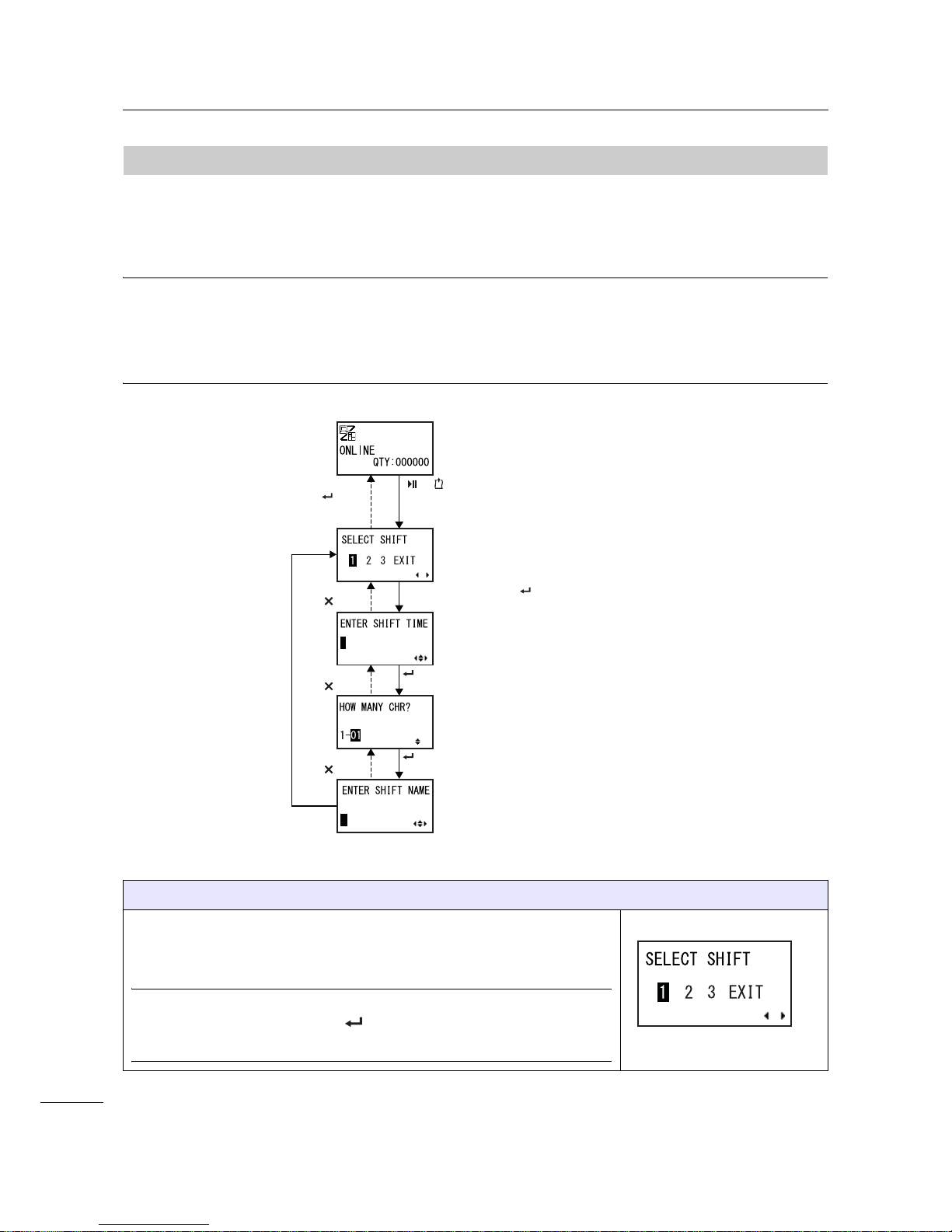
4 Operation and Configuration
62
S84-ex/S86-ex Operator Manual
4.2.6
Work Shift Setting Mode
This mode allows for specific production shift information to be printed on a label when used with the
printer SBPL command.
The flowchart shows the sequence of the setting screens for the work shift mode. The table describes
each setting screen in detail.
Note
• This mode is enabled only if SHIFT CODE is set to YES in the hidden setting mode.
• You can set up to three shifts depending on the number of work shifts required in the field. For exam-
ple, if two shifts are required, set work shift number 1 and 2.
SELECT SHIFT
Select the work shift number to store the work shift setting.
You can select the work shift number from 1 to 3.
Note
If you select EXIT and press the ENTER button, the printer returns to
the online screen.
(Press for 5 seconds)
buttons
+
* When SHIFT CODE is set to YES in the hidden setting mode
Select EXIT
+ button
Select other than EXIT + button
button
button
button
button
button

4 Operation and Configuration
63
S84-ex/S86-ex Operator Manual
ENTER SHIFT TIME
Set the printer start time in 24-hour format.
Press the
/ buttons to shift the cursor and press the / bu ttons to
change the value.
Press the ENTER button to save the value and proceed to the next
setting screen.
HOW MANY CHR?
Set the character size of the SHIFT NAME by specifying the number of
characters.
Select the number of characters using the
/ buttons and then press
the ENTER button.
The setting range is from 01 to 16.
ENTER SHIFT NAME
Specify a name for the work shift.
Available characters are A to Z, space and 0 to 9.
The number of characters you can enter depends on the character size se t
in the HOW MANY CHR? screen.
Press the
/ buttons to shift the cursor and press the / bu ttons to
set the character.
Press the ENTER button to save the work shift name.

4 Operation and Configuration
64
S84-ex/S86-ex Operator Manual
4.2.7
Simple Standalone Mode
This mode allows the printer to function independently from a host computer once a fixed format has
been sent and saved to the SD card or USB memory.
The data may be saved to the SD card or USB memory while in the print buffer, then recalled later with a
new print quantity specified. The SD card or USB memory can hold a maximum of nine formats.
However, one file number will only hold a single format; new format will overwrite the existing saved
format. The host computer must be reconnected to the printer to overwrite an existing format.
The flowchart shows the sequence of the setting screens for the simple standalone mode. The table
describes each setting screen in detail.
* Press the , , or button to
select an item or set the value
accordingly. The active arrow icons
are shown on the screen.
or button
button
button
button
button
Select LOAD
+ button
Select SAVE
+ button
button
button
button
button
button
(Press for 5 seconds)
Select YES
+ button
button
button
button
button
button
button
button
button
button
button
button
Shows only when there is
sequential data.
Select NO + button
button

4 Operation and Configuration
65
S84-ex/S86-ex Operator Manual
STANDALONE MODE
Select the following options using the / buttons and then press the
ENTER button.
• LOAD: Read and print the file.
• SAVE: Save the received print data to a file.
Note
Three beeps will sound if you select SAVE and press
the ENTER
button when there is no received data.
INTERFACE SELECT
Select the memory type using the / buttons and then press the
ENTER button.
Note
Three beeps will sound if the connected memory has no data to load or the
selected memory is not connected.
SELECT NUMBER
Select the file number using the / buttons and then press the
ENTER button to load the specified file or save the received data.
The setting range is from 01 to 09.
DATA EXISTS, OVERWRITE?
This screen confirms that you are overwriting a file if you have selected to
save to an existing file number.
Select the following options using the
/ buttons and then press the
ENTER button.
• YES: Overwrite the existing file.
• NO: Cancel the overwrite and return to the SELECT NUMBER screen.
Note
Make sure that you do not need the existing file before overwriting it.
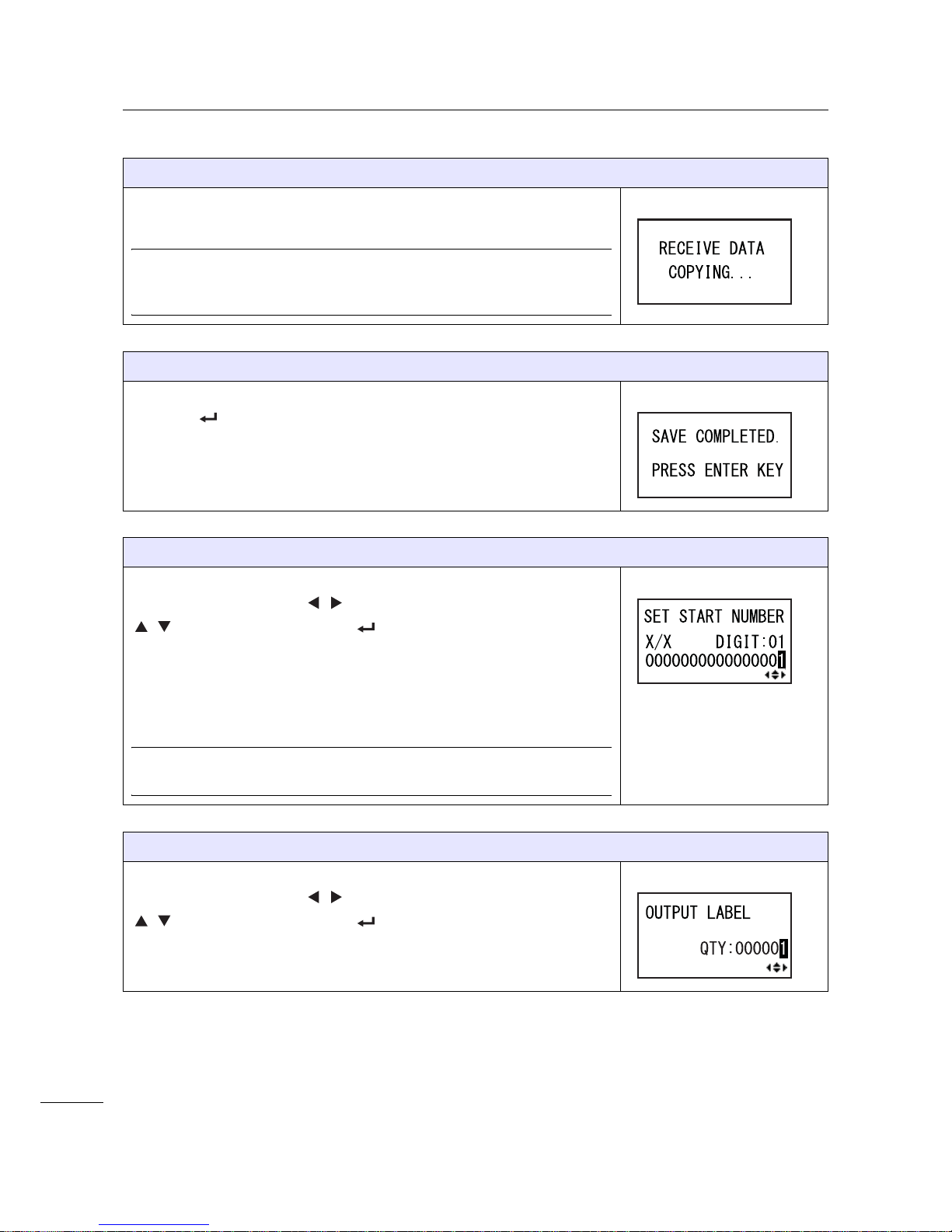
4 Operation and Configuration
66
S84-ex/S86-ex Operator Manual
RECEIVE DATA COPYING. . .
This screen shows that the received data is being copied.
SAVE COMPLETED shows when the received data is fully copied.
Note
Three beeps will sound if the printer fails to copy the received data. The
printer returns to the STANDALONE MODE screen.
SAVE COMPLETED.
This screen shows when the received data is saved to a specified file.
Press the ENTER button to return to the STANDALONE MODE
screen.
SET START NUMBER
This is the edit screen of the sequential data included in the read data.
Move the cursor using the
/ buttons, change the value using the
/
buttons and then press the ENTER button.
The "X/X" in the screen shows the currently edited sequential data number
and total sequential data number.
DIGIT is the digit number of the selected cursor.
The screen may be decimal or hex according to the read data.
The maximum number of DIGIT is 99.
Note
Shows only when there is sequential data.
OUTPUT LABEL
This screen allows you to specify the print number.
Move the cursor using the
/ buttons, change the value using the
/
buttons and then press the ENTER button.
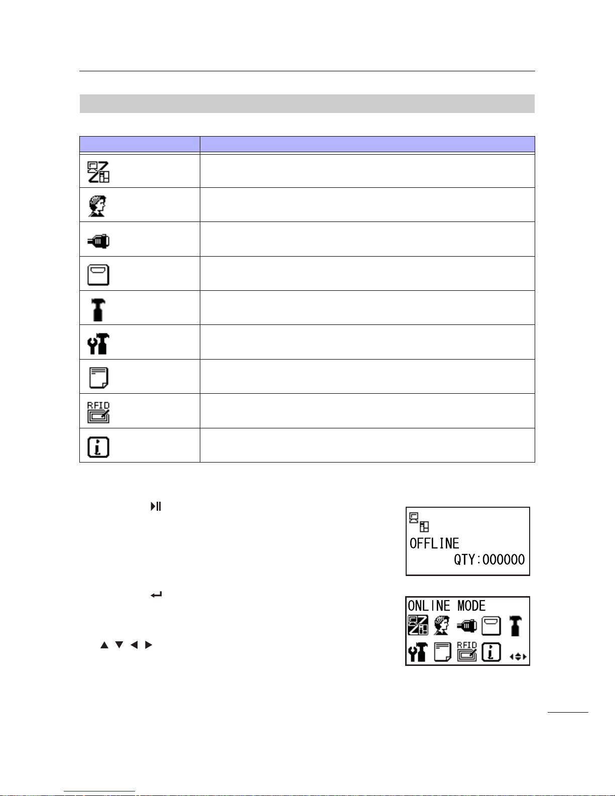
4 Operation and Configuration
67
S84-ex/S86-ex Operator Manual
4.2.8
Setting Mode Menu
In the settings mode menu, the setting modes are shown as follows:
Select the setting mode according to the following procedure:
1 Press the LINE button to change the
printer to offline mode.
The printer changes to offline mode.
2 Press the ENTER button.
The printer changes to the setting mode menu.
3 Select the setting mode using the
/// buttons.
The selected setting mode shows on the screen and
the icon is highlighted by inverting its colors.
Menu Description
Online mode
Returns to online mode.
User mode
Access the settings related to the basic user configurations.
Interface mode
Access the settings related to the interfaces.
Memory mode
Access the settings related to the memory.
Service mode
Access the settings related to the media sensor adjustment and various
functions activation.
Advanced mode
Access the settings related to the advanced printer configurations.
Hex dump mode
Access and print the hex dump for troubleshooting.
RFID mode
Access the settings related to the optional RFID module.
Shows only when the optional RFID is installed.
Information mode
Access the information of this printer.
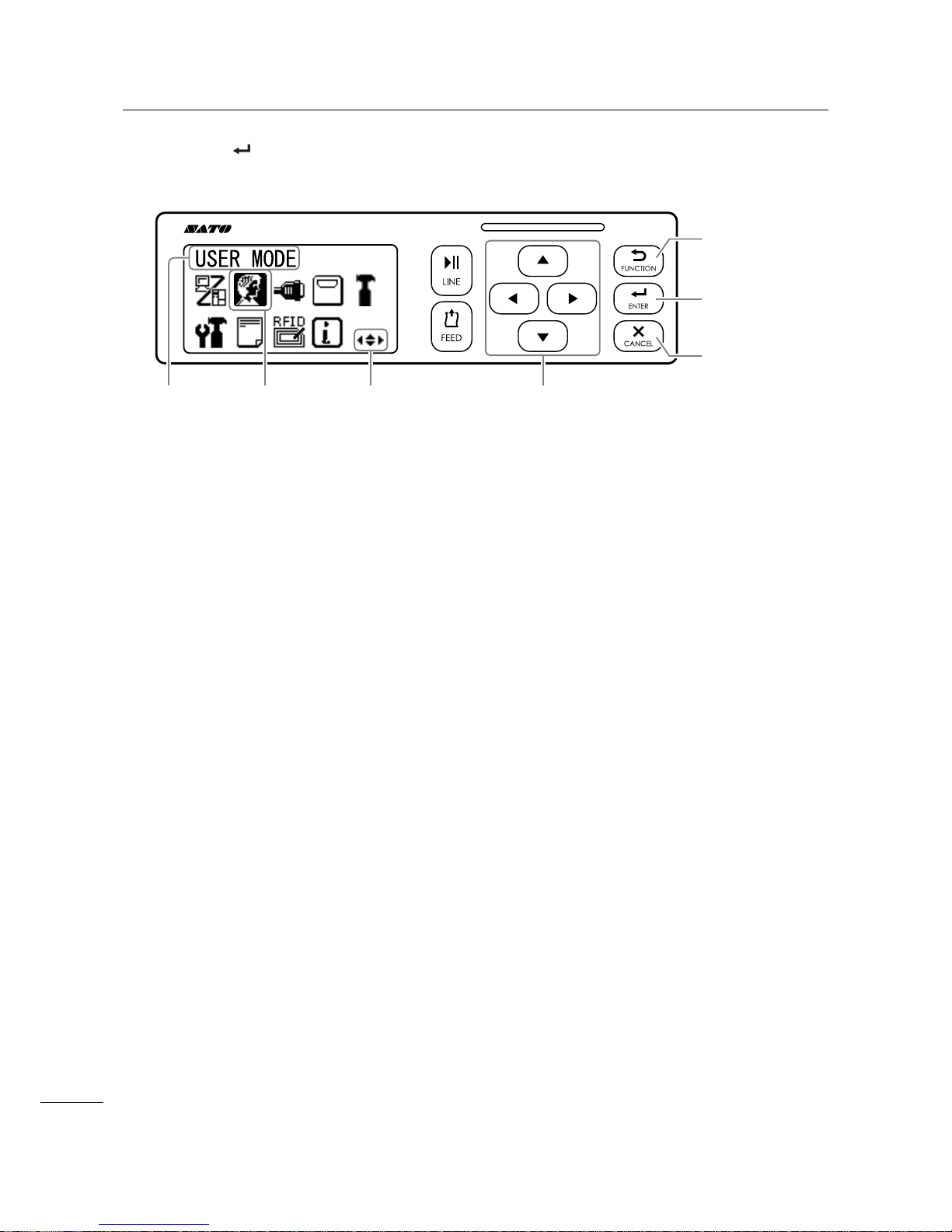
4 Operation and Configuration
68
S84-ex/S86-ex Operator Manual
4 Press the ENTER button to enter the selected mode.
The functions of the buttons in the setting mode menu are shown as below.
Enters the
selected setting
mode.
Navigate to
select the
setting mode.
Enters offline
mode.
Enters offline
mode.
Selected icon
highlighted
with inverted
colors.
Valid arrow buttons
for selection.
Selected
setting
mode

4 Operation and Configuration
69
S84-ex/S86-ex Operator Manual
4.2.9
User Mode
The flowchart shows the sequence of the setting screens for the user mode. The table describes each
setting screen in detail.
Shows only when the
PASSWORD input is enabled
* Press the , , or button to
select an item or set the value
accordingly. The active arrow icons
are shown on the screen.
button
button
button
button
button
button
button
button
button
button
button
button
button
button
button
button
button
button
button
button
button
button
button
button
Shows only when GB18030
is selected
button
Proceed to .
U-A
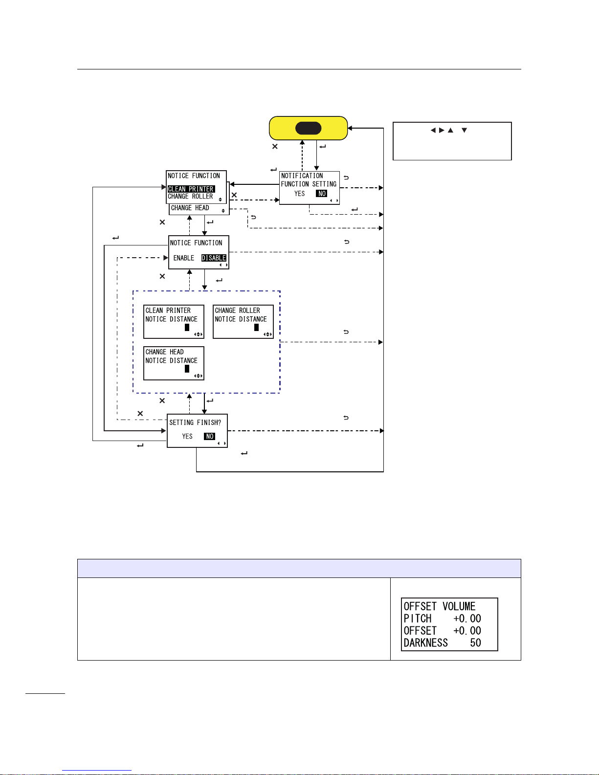
4 Operation and Configuration
70
S84-ex/S86-ex Operator Manual
OFFSET VOLUME
The setting values of the adjustment mode are shown.
• PITCH: Shows the print position offset value.
• OFFSET: Shows the stop position offset value.
• DARKNESS: Shows the darkness setting value.
You can change these values in Adjustment Mode and Test Print Mode.
* Press the , , or button to
select an item or set the value
accordingly. The active arrow icons
are shown on the screen.
button
button
button
button
button
button
button
Select NO + button
button
Select ENABLE
+ button
button
P
NP
NP
button
button
Select DISABLE
+ button
button
Select YES +
button
button
button
Select NO + button
Select YES + button
U-A

4 Operation and Configuration
71
S84-ex/S86-ex Operator Manual
PRINT SPEED
The setting range varies depending on the model.
• S84-ex (203 dpi): 4 to 16 ips (inches/sec)
• S86-ex (203 dpi): 4 to 14 ips (inches/sec)
• S84-ex (305 dpi): 4 to 14 ips (inches/sec)
• S86-ex (305 dpi): 4 to 12 ips (inches/sec)
• S84-ex (609 dpi): 2 to 6 ips (inches/sec)
Note
Setting the print speed to a level that is too fast may affect the print quality.
PRINT DARKNESS
Specify the print darkness from ten steps.
The setting range is from 1 to 10. 1 is the lightest and 10 is the darkest.
PITCH OFFSET
This setting adjusts the pitch offset value.
The media pitch is the distance between the leading edge (the edge that
comes out of the printer first) of the media and the leading edge of the next
media. Once the position has been set, it can be fine adjusted using the
PITCH POSITION in adjustment mode.
The setting range is from -49 mm (-1.9”) to +49 mm (+1.9”) and is
adjustable by 1 mm (0.04”) steps.
Set the offset value with '+' to move the print position opposite the feed
direction and value with '-' to move the print position in the feed direction.
CHARACTER CODE
Set the character code to be used.
• UTF-8: Use UTF-8 for character encoding.
• UTF-16: Use UTF-16 for character encoding.

4 Operation and Configuration
72
S84-ex/S86-ex Operator Manual
2 BYTE FONTS
Set the kanji code to be used.
• GB18030: Set for use with simplified Chinese.
• BIG5: Set for use with traditional Chinese.
• KSX1001: Set for use with Korean.
The following kanji codes are available when GB18030 is selected:
• MINCHO: Print the kanji code using MINCHO.
• GOTHIC: Print the kanji code using GOTHIC.
NOTIFICATION FUNCTION SETTING
Select whether or not to set the notification function.
• YES: Set the notification function.
• NO: Do not set the notification function. The screen returns to user
mode.
Note
For details on the media motion when the set notification interval has
reached, refer to Section 7.6 Notification Function.
NOTICE FUNCTION (SELECT)
Select the items for notification.
• CLEAN PRINTER: Notify when to perform cleaning of the printer.
• CHANGE ROLLER: Notify when to perform replacement of the platen
roller.
• CHANGE HEAD: Notify when to perform replacement of the print head.
NOTICE FUNCTION (ENABLE/DISABLE)
Enable or disable the notification for the item selected in the above
NOTICE FUNCTION.
• ENABLE: Enable the notification function.
• DISABLE: Disable the notification function.

4 Operation and Configuration
73
S84-ex/S86-ex Operator Manual
CLEAN PRINTER
Set the notification distance for cleaning the printer.
The setting range is from 000 to 999 m.
Note
The notification function will be disabled if the distance is set to 0.
CHANGE ROLLER
Set the notification distance for changing the platen roller.
The setting range is from 000 to 150 km.
Note
The notification function will be disabled if the distance is set to 0.
CHANGE HEAD
Set the notification distance for changing the print head.
The setting range is from 000 to 150 km.
Note
The notification function will be disabled if the distance is set to 0.
SETTING FINISH?
Confirm to complete the setting.
• YES: Returns to the user mode screen.
• NO: Returns to the NOTICE FUNCTION screen to select an item.
P
NP
NP

4 Operation and Configuration
74
S84-ex/S86-ex Operator Manual
4.2.10
Interface Mode
The flowchart shows the sequence of the setting screens for the interface mode. The table describes
each setting screen in detail.
Setting contents vary depending on the interface.
Select NO +
button
Shows only when the
PASSWORD input is
enabled
Select YES +
button
Select “SUB PORT” + button
Select “DATA PORT”
+ button
Select “USB”/ “LAN”/ “RS-232C”/ “IEEE1284”
/“Bluetooth”/“WLAN”+ button
Select “NONE” + button
Proceed to .
button
button
button
button
button
button
button
button
button
button
button
button
* Press the , , or button to select an item or set the value
accordingly. The active arrow icons are shown on the screen.
* Pressing the button on each screen will revert to the
INTERFACE MODE menu.
button
To the USB setting
To the LAN/WLAN setting
To the RS-232C setting
To the IEEE1284 setting
To the Bluetooth setting
I-F
I-A
I-D
I-B
I-C
I-E

4 Operation and Configuration
75
S84-ex/S86-ex Operator Manual
PRESS ENTER KEY
This screen reminds the user to press the ENTER button to change or
power off the printer to save the setting.
Shows only when
PROTOCOL is set to
STATUS 4.
Shows only when
the
calendar IC is
installed and a LAN
connection is
established.
button
Shows only when
Data Port is selected.
button
button
button
button
Select “DISABLE”
+ button
Select “ENABLE” +
button
button
button
button
button
button
Return to INTERFACE
MODE menu.
* Press the , , or button to select an item or set the value
accordingly. The active arrow icons are shown on the screen.
* Pressing the button on each screen will revert to the
INTERFACE MODE menu.
button
I-F

4 Operation and Configuration
76
S84-ex/S86-ex Operator Manual
INTERFACE AUTO SELECT
Enable or disable the interface auto detection.
• ENABLE: Automatically select the connected interface.
• DISABLE: The interface is selected based on the interface setting.
Note
The setting will be effective only when you power on the printer again.
INTERFACE SETTING
Set whether or not to perform the interface settings.
• YES: Enter the PORT SELECT screen.
• NO: Enter the IGNORE CR/LF screen.
PORT SELECT
Select the port used for the connected interface.
• DATA PORT: For receiving various SBPL commands and executing
print operations.
• SUB PORT: For monitoring the printer status and connecting to exter-
nal devices.
DATA PORT
Select the connected interface for use with the data port.
One of the following interfaces can be selected.
•USB
•LAN
• RS-232C
• IEEE1284
• Bluetooth
•WLAN
Note
• Bluetooth shows only when a Bluetooth adapter is connected.
• WLAN shows only if a WLAN unit is installed.
• You cannot select the interface that has already been set for the SUB
PORT.
• The setting will be effective only when you power on the printer again.

4 Operation and Configuration
77
S84-ex/S86-ex Operator Manual
SUB PORT
Select the connected interface for use with the data port.
One of the following interfaces can be selected.
•USB
•LAN
• RS-232C
• IEEE1284
• Bluetooth
• WLAN
•NONE
Note
• Bluetooth shows only when a Bluetooth adapter is connected.
• WLAN shows only if a WLAN unit is installed.
• You cannot select the interface that has already been set for the DATA
PORT.
• The setting will be effective only when you power on the printer again.
IGNORE CR/LF
Ignore or acknowledge the CR/LF code of the received data.
• YES: Ignore the CR/LF code.
• NO: Do not ignore the CR/LF code.
Note
Shows only if the DATA PORT is selected.
IGNORE CAN/DLE
Ignore or acknowledge the CAN/DLE code of the received data.
• YES: Ignore the CAN/DLE code.
• NO: Do not ignore the CAN/DLE code.
Note
Shows only if PROTOCOL is set to STATUS4.
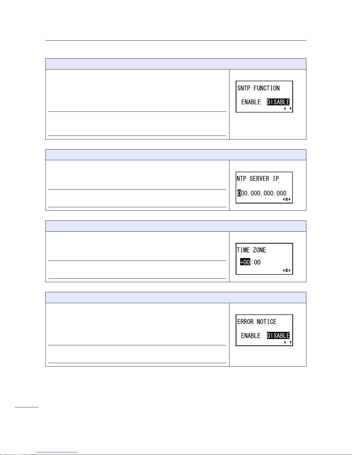
4 Operation and Configuration
78
S84-ex/S86-ex Operator Manual
SNTP FUNCTION
Enable or disable the SNTP function.
• ENABLE: Perform the time correction of the calendar IC.
• DISABLE: Do not perform the time correction of the calendar IC.
Note
Shows only when the calendar IC is installed and the LAN interface is
selected.
NTP SERVER IP
Set the NTP server IP address.
Note
Shows only when the SNTP function is enabled.
TIME ZONE
Set the time zone.
The setting range is from -12:45 to +14:45.
Note
Shows only when the SNTP function is enabled.
ERROR NOTICE
Set whether or not to notify the SNTP function error.
• ENABLE: Shows an error notice when failing to correct the time.
• DISABLE: Does not show an error notice when failing to correct the
time.
Note
Shows only when the SNTP function is enabled.
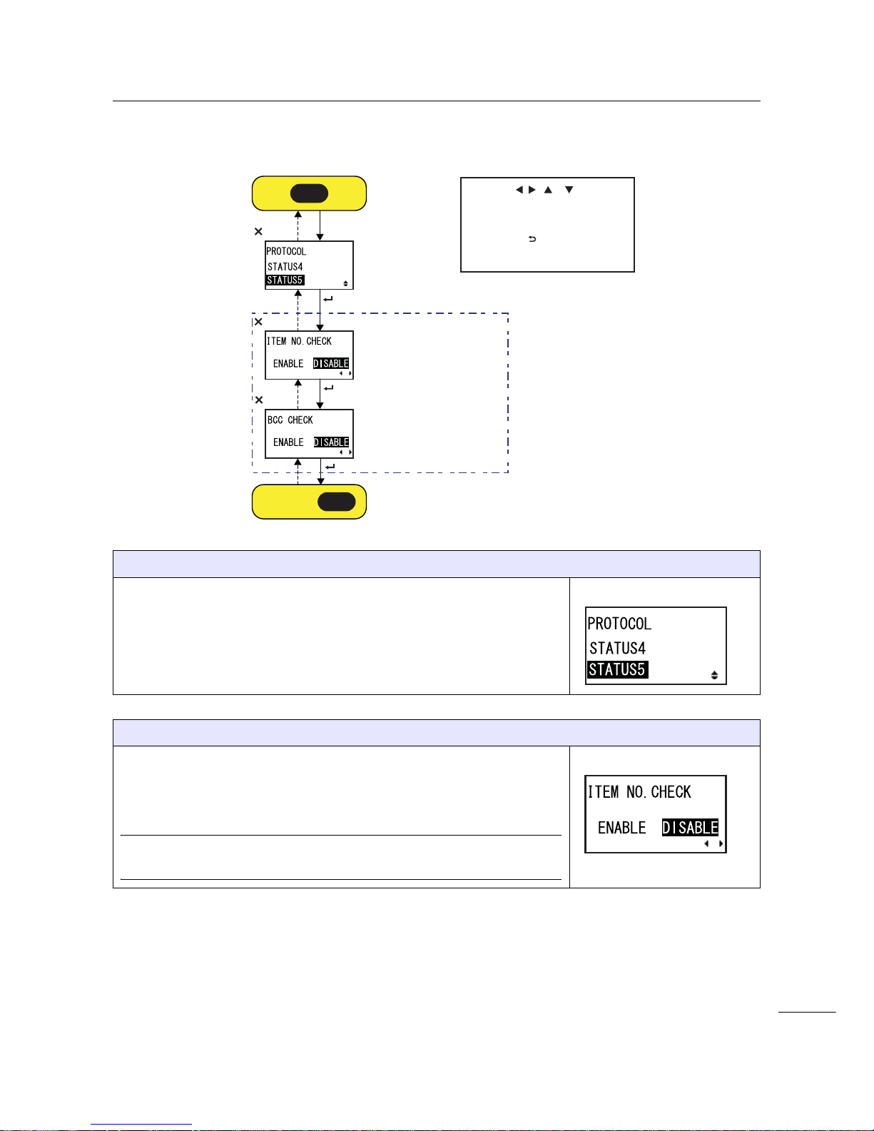
4 Operation and Configuration
79
S84-ex/S86-ex Operator Manual
USB Setting
PROTOCOL
Set the communication protocol.
• STATUS4: When selected, the printer will proceed to the IGNORE CR/
LF screen.
• STATUS5: When selected, the printer will proceed to the ITEM NO.
CHECK screen.
ITEM NO. CHECK
Set the item number check function.
• ENABLE: Enable the item number check function.
• DISABLE: Disable the item number check function.
Note
Shows only when PROTOCOL is set to STATUS5.
Shows only when
STATUS5 is selected.
* Press the , , or button to
select an item or set the value
accordingly. The active arrow icons
are shown on the screen.
* Pressing the button on each
screen will revert to the INTERFACE
MODE menu.
button
button
button
button
button
button
I-A
Proceed to .
I-F
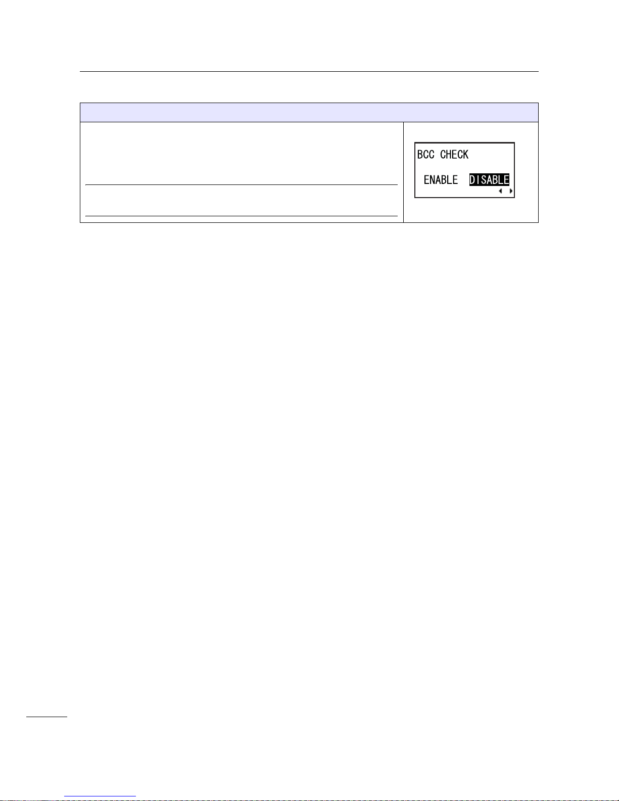
4 Operation and Configuration
80
S84-ex/S86-ex Operator Manual
BCC CHECK
Set the BCC check function.
• ENABLE: Enable the BCC check function.
• DISABLE: Disable the BCC check function.
Note
Shows only when PROTOCOL is set to STATUS5.
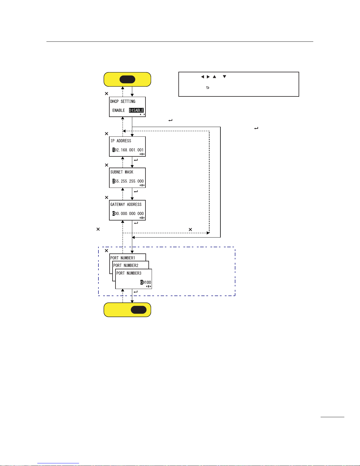
4 Operation and Configuration
81
S84-ex/S86-ex Operator Manual
LAN/Wireless LAN Setting
* Press the , , or button to select an item or set the value
accordingly. The active arrow icons are shown on the screen.
* Pressing the button on each screen will revert to the
INTERFACE MODE menu.
DHCP DISABLE + button
DHCP ENABLE + button
DHCP ENABLE + button
DHCP DISABLE
+ button
button
button
button
button
button
button
button
Shows only when
LAN is selected.
button
button
I-B
Proceed to .
I-L
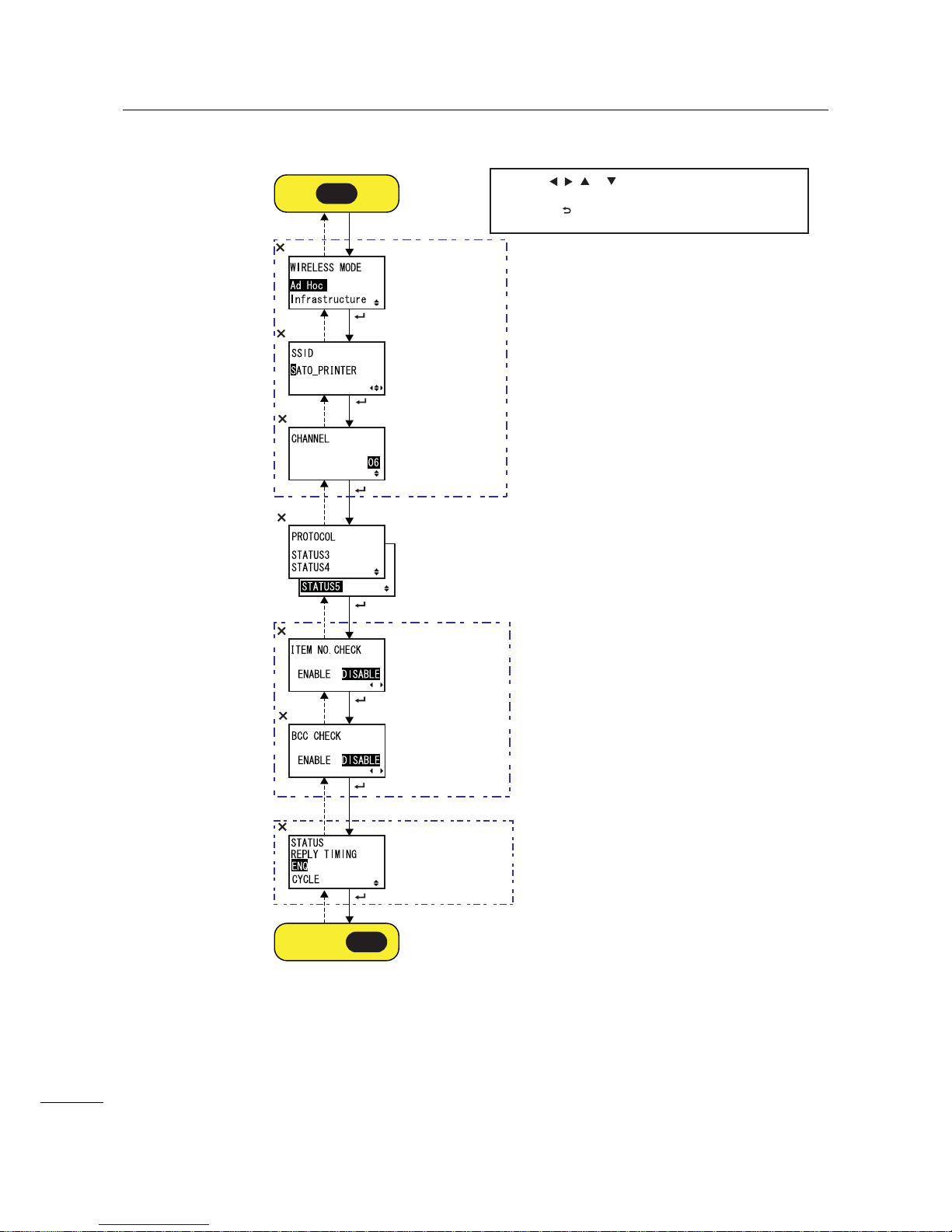
4 Operation and Configuration
82
S84-ex/S86-ex Operator Manual
Shows only
when STATUS5
is selected.
Shows only
when STATUS4
is selected.
Shows only
when the
Wireless LAN
adapter is
installed and
WLAN is
selected.
* Press the , , or button to select an item or set the value
accordingly. The active arrow icons are shown on the screen.
* Pressing the button on each screen will revert to the
INTERFACE MODE menu.
button
button
button
button
button
button
button
button
button
button
button
button
button
button
I-L
Proceed to .
I-F
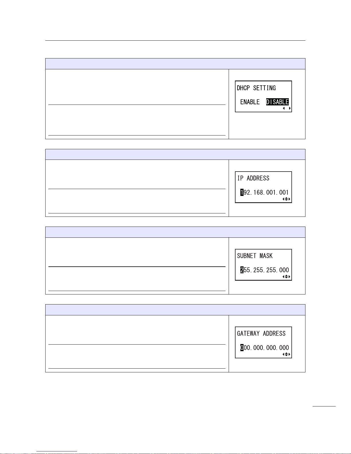
4 Operation and Configuration
83
S84-ex/S86-ex Operator Manual
DHCP SETTING
Enable or disable DHCP.
• ENABLE: Enable DHCP.
• DISABLE: Disable DHCP.
Note
• Shows only if the LAN or WLAN interface is selected.
• The setting for the WLAN interface will be effective only when you
power on the printer again.
IP ADDRESS
Set the IP address.
The setting range is from 0.0.0.0 to 255.255.255.255.
The default value is 192.168.001.001.
Note
• Shows only if the LAN or WLAN interface is selected.
• The setting will be effective only when you power on the printer again.
SUBNET MASK
Set the subnet mask address.
The setting range is from 0.0.0.0 to 255.255.255.255.
The default value is 255.255.255.000.
Note
• Shows only if the LAN or WLAN interface is selected.
• The setting will be effective only when you power on the printer again.
GATEWAY ADDRESS
Set the gateway address.
The setting range is from 0.0.0.0 to 255.255.255.255.
The default value is 000.000.000.000.
Note
• Shows only if the LAN or WLAN interface is selected.
• The setting will be effective only when you power on the printer again.

4 Operation and Configuration
84
S84-ex/S86-ex Operator Manual
PORT NUMBER
Set the LAN port numbers, 1 to 3.
The setting range is from 00001 to 65535.
Note
• Shows only if the LAN interface is selected.
• Each port (1, 2 and 3) must be set to different values.
• The setting will be effective only when you power on the printer again.
WIRELESS MODE
Set the communication method of the wireless LAN.
The options are as follows:
•Ad Hoc
• Infrastructure
Note
• Shows only if the WLAN interface is selected.
• The setting will be effective only when you power on the printer again.
SSID
Set the SSID of the wireless LAN.
You can enter a maximum of thirty-two characters including alphabet
(upper case and lower case), numbers and symbols.
Note
• Shows only if the WLAN interface is selected.
• The setting will be effective only when you power on the printer again.
CHANNEL
Set the communication channel of the wireless LAN.
The setting range is from 01 to 13 and the default value is 06.
Note
• Shows only if the WLAN interface is selected.
• The setting will be effective only when you power on the printer again.
• When the channel has become invalid due to a region code change,
the channel returns to its default setting.
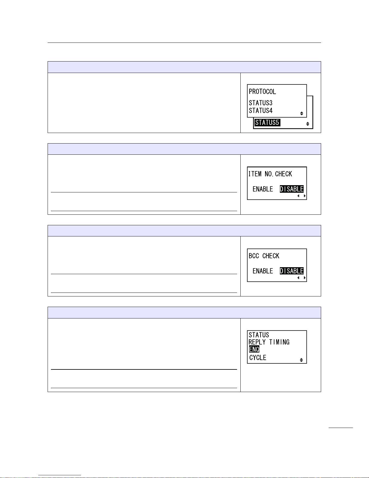
4 Operation and Configuration
85
S84-ex/S86-ex Operator Manual
PROTOCOL
Set the communication protocol.
• STATUS3: When selected, the printer will proceed to the IGNORE CR/
LF screen.
• STATUS4: When selected, the printer will proceed to the STATUS
REPLY TIMING screen.
• STATUS5: When selected, the printer will proceed to the ITEM NO.
CHECK screen.
ITEM NO. CHECK
Set the item number check function.
• ENABLE: Enable the item number check function.
• DISABLE: Disable the item number check function.
Note
Shows only when PROTOCOL is set to STATUS5.
BCC CHECK
Set the BCC check function.
• ENABLE: Enable the BCC check function.
• DISABLE: Disable the BCC check function.
Note
Shows only when PROTOCOL is set to STATUS5.
STATUS REPLY TIMING
Set the timing for replying with the status information to the host.
• ENQ: Returns a status after receiving a Status Request (ENQ), which
has been sent from the host.
• CYCLE: Returns a status from the printer to the host at an interval of
500 ms.
Note
Shows only when PROTOCOL is set to STATUS4.
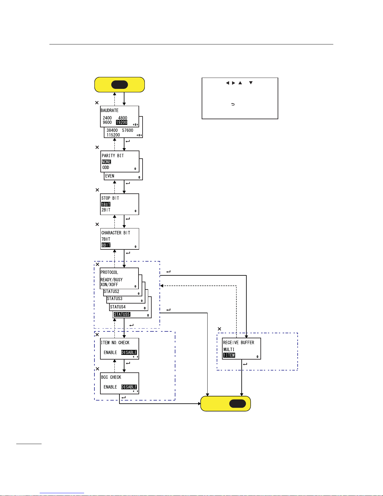
4 Operation and Configuration
86
S84-ex/S86-ex Operator Manual
RS-232C Setting
Select READY/BUSY or XON/XOFF
+ button
Select STATUS2,
STATUS3 or STATUS4
+ button
Shows only
when STATUS5
is selected
Shows only
when
READY/BUSY
or XON/XOFF is
selected
* Press the , , or button to
select an item or set the value
accordingly. The active arrow icons
are shown on the screen.
* Pressing the button on each
screen will revert to the INTERFACE
MODE menu.
button
button
button
button
button
button
button
button
button
button
button
Select STATUS5
+ button
button
button
button
button
I-C
Proceed to .
I-F
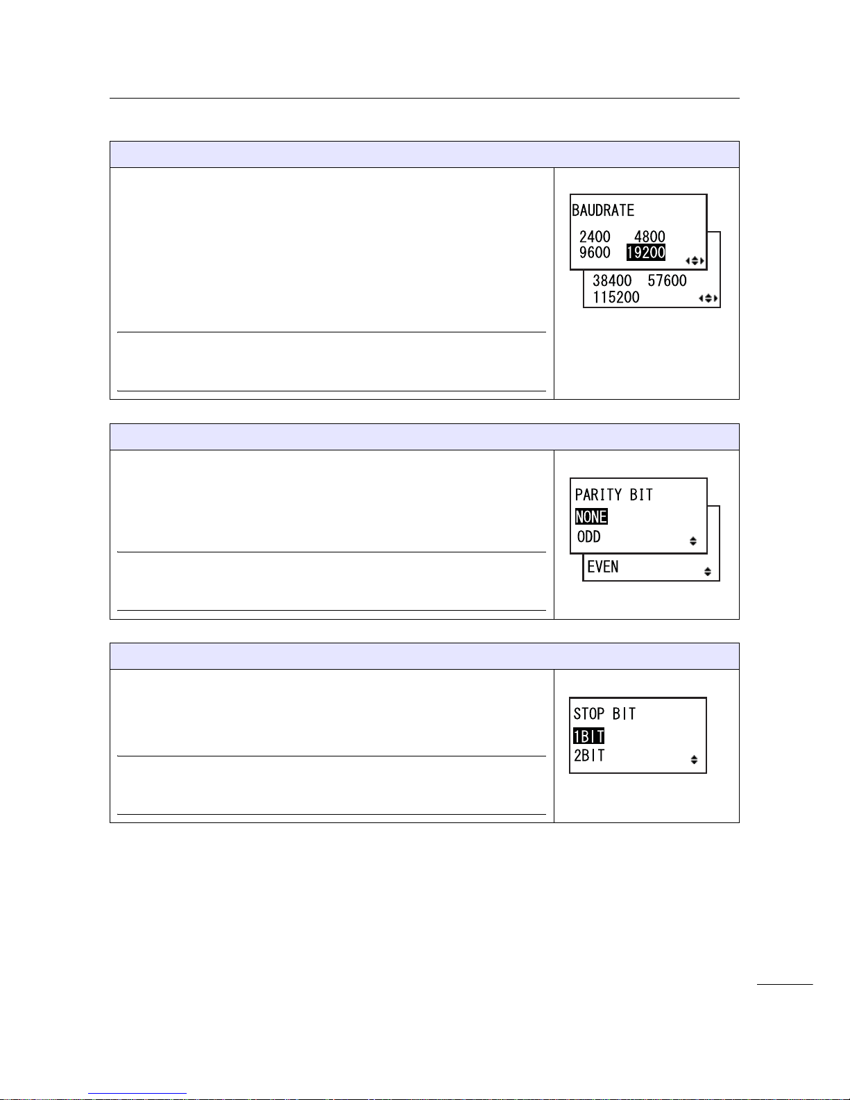
4 Operation and Configuration
87
S84-ex/S86-ex Operator Manual
BAUDRATE
Set the RS-232C baud rate.
The following baud rates are available:
•2400 (bps)
•4800 (bps)
•9600 (bps)
• 19200 (bps)
• 38400 (bps)
• 57600 (bps)
• 115200 (bps)
Note
• Shows only if the RS-232C interface is selected.
• The setting will be effective only when you power on the printer again.
PARITY BIT
Set the RS-232C parity bit.
The following options are available:
•NONE
•ODD
• EVEN
Note
• Shows only if the RS-232C interface is selected.
• The setting will be effective only when you power on the printer again.
STOP BIT
Set the RS-232C stop bit.
The following options are available:
•1BIT
•2BIT
Note
• Shows only if the RS-232C interface is selected.
• The setting will be effective only when you power on the printer again.

4 Operation and Configuration
88
S84-ex/S86-ex Operator Manual
CHARACTER BIT
Set the RS-232C data length.
The following options are available:
•7BIT
•8BIT
Note
• Shows only if the RS-232C interface is selected.
• The setting will be effective only when you power on the printer again.
PROTOCOL
Set the communication protocol.
• READY/BUSY: When selected, the printer will proceed to the
RECEIVE BUFFER screen.
• XON/OFF: When selected, the printer will proceed to the RECEIVE
BUFFER screen.
• STATUS2: When selected, the printer will proceed to the IGNORE CR/
LF screen.
• STATUS3: When selected, the printer will proceed to the IGNORE CR/
LF screen.
• STATUS4: When selected, the printer will proceed to the IGNORE CR/
LF screen.
• STATUS5: When selected, the printer will proceed to the ITEM NO.
CHECK screen.
Note
The setting will be effective only when you power on the printer again.
ITEM NO. CHECK
Set the item number check function.
• ENABLE: Enable the item number check function.
• DISABLE: Disable the item number check function.
Note
Shows only when PROTOCOL is set to STATUS5.
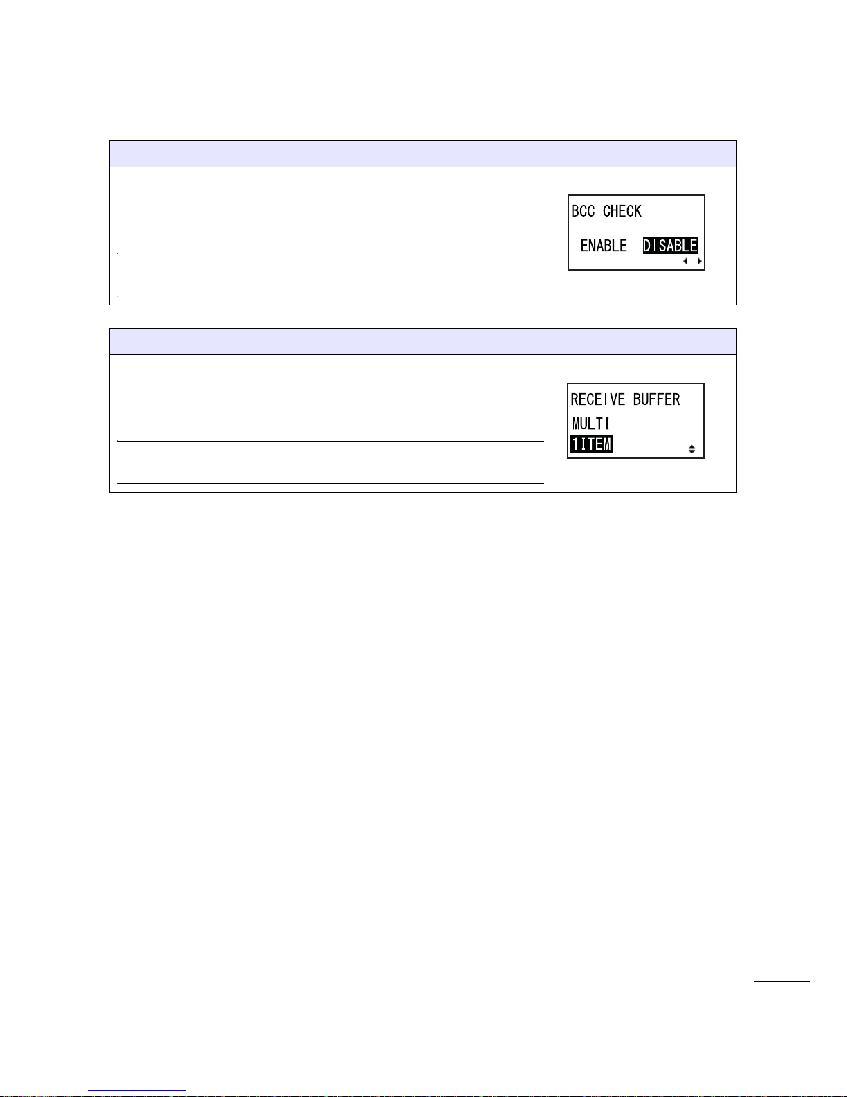
4 Operation and Configuration
89
S84-ex/S86-ex Operator Manual
BCC CHECK
Set the BCC check function.
• ENABLE: Enable the BCC check function.
• DISABLE: Disable the BCC check function.
Note
Shows only when PROTOCOL is set to STATUS5.
RECEIVE BUFFER
Set the receive buffer type.
• MULTI: Multiple receive buffers.
• 1ITEM: A single receive buffer.
Note
Shows only when PROTOCOL is set to READY/BUSY or XON/XOFF.

4 Operation and Configuration
90
S84-ex/S86-ex Operator Manual
IEEE1284 Setting
Shows only
when STATUS5
is selected
Shows only
when STATUS4
is selected
Shows only when
RECEIVE
BUFFER is set to
1ITEM.
* Press the , , or button to
select an item or set the value
accordingly. The active arrow icons
are shown on the screen.
* Pressing the button on each
screen will revert to the INTERFACE
MODE menu.
button
button
button
button
button
button
button
button
button
button
I-D
Proceed to .
I-F

4 Operation and Configuration
91
S84-ex/S86-ex Operator Manual
PROTOCOL
Set the communication protocol.
• STATUS4: When selected, the printer will proceed to the RECEIVE
BUFFER screen.
• STATUS5: When selected, the printer will proceed to the ITEM NO.
CHECK screen.
ITEM NO. CHECK
Set the item number check function.
• ENABLE: Enable the item number check function.
• DISABLE: Disable the item number check function.
Note
Shows only when PROTOCOL is set to STATUS5.
BCC CHECK
Set the BCC check function.
• ENABLE: Enable the BCC check function.
• DISABLE: Disable the BCC check function.
Note
Shows only when PROTOCOL is set to STATUS5.
RECEIVE BUFFER
Set the receive buffer type.
• MULTI: Multiple receive buffers.
• 1ITEM: A single receive buffer.
Note
Shows only when PROTOCOL is set to STATUS4.

4 Operation and Configuration
92
S84-ex/S86-ex Operator Manual
IEEE1284 ACK SIGNAL
Set the width of the IEEE1284 ACK signal.
The setting range is from 00.5 µs to 12.0 µs, and is adjustable in 0.1 µs
steps.
Note
Shows only if the IEEE1284 interface is selected and RECEIVE BUFFER
is set to 1ITEM.

4 Operation and Configuration
93
S84-ex/S86-ex Operator Manual
Bluetooth Setting
* Press the , , or button to
select an item or set the value
accordingly. The active arrow icons
are shown on the screen.
* Pressing the button on each
screen will revert to the INTERFACE
MODE menu.
button
button
button
button
button
button
button
button
button
button
button
button
button
button
button
button
button
button
button
button
Shows only
when ENABLE
is selected
I-E
Proceed to .
I-F
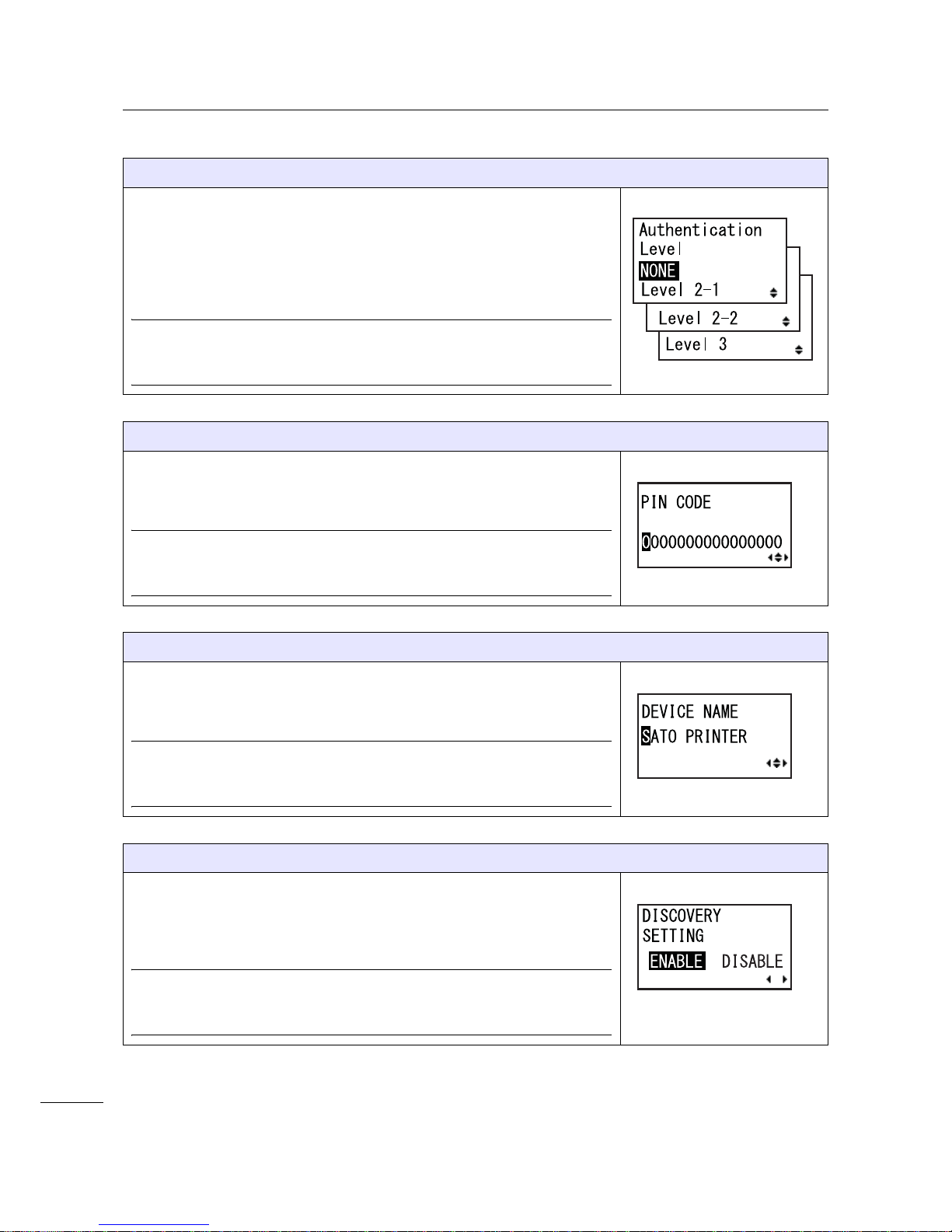
4 Operation and Configuration
94
S84-ex/S86-ex Operator Manual
AUTHENTICATION LEVEL
Set the Bluetooth authentication level.
The following options are available:
• NONE: No authentication
• Level 2-1: PIN code authentication, service level
• Level 2-2: PIN code authentication, service level
• Level 3: PIN code authentication, link level
Note
• Shows only if the Bluetooth interface is selected.
• The setting will be effective only when you power on the printer again.
PIN CODE
Set the Bluetooth PIN code.
You can enter a maximum of sixteen characters including alphabet (upper
case and lower case), numbers and symbols.
Note
• Shows only if the Bluetooth interface is selected.
• The setting will be effective only when you power on the printer again.
DEVICE NAME
Set the device name for the printer.
You can enter a maximum of twenty characters including alphabet (upper
case and lower case), numbers and symbols.
Note
• Shows only if the Bluetooth interface is selected.
• The setting will be effective only when you power on the printer again.
DISCOVERY SETTING
Enable or disable the Bluetooth detection response.
• ENABLE: Enable the Bluetooth detection response.
• DISABLE: Disable the Bluetooth detection response.
Note
• Shows only if the Bluetooth interface is selected.
• The setting will be effective only when you power on the printer again.

4 Operation and Configuration
95
S84-ex/S86-ex Operator Manual
PARAMETER SETTING(ISI)
Set the Bluetooth communication parameter (ISI).
The setting range is from 0012 to 1000.
Note
• Shows only if the Bluetooth interface is selected and DETECTING
SETTING is enabled.
• You cannot set the ISI value if it is smaller than the ISW value.
• The setting will be effective only when you power on the printer again.
PARAMETER SETTING(ISW)
Set the Bluetooth communication parameter (ISW).
The setting range is from 0011 to 1000.
Note
• Shows only if the Bluetooth interface is selected and DETECTING
SETTING is enabled.
• You cannot set the ISW value if it is greater than the ISI value.
• The setting will be effective only when you power on the printer again.
PARAMETER SETTING(PSI)
Set the Bluetooth communication parameter (PSI).
The setting range is from 0012 to 1000.
Note
• Shows only if the Bluetooth interface is selected.
• You cannot set the PSI value if it is smaller than the PSW value.
• The setting will be effective only when you power on the printer again.
PARAMETER SETTING(PSW)
Set the Bluetooth communication parameter (PSW).
The setting range is from 0011 to 1000.
Note
• Shows only if the Bluetooth interface is selected.
• You cannot set the PSW value if it is greater than the PSI value.
• The setting will be effective only when you power on the printer again.
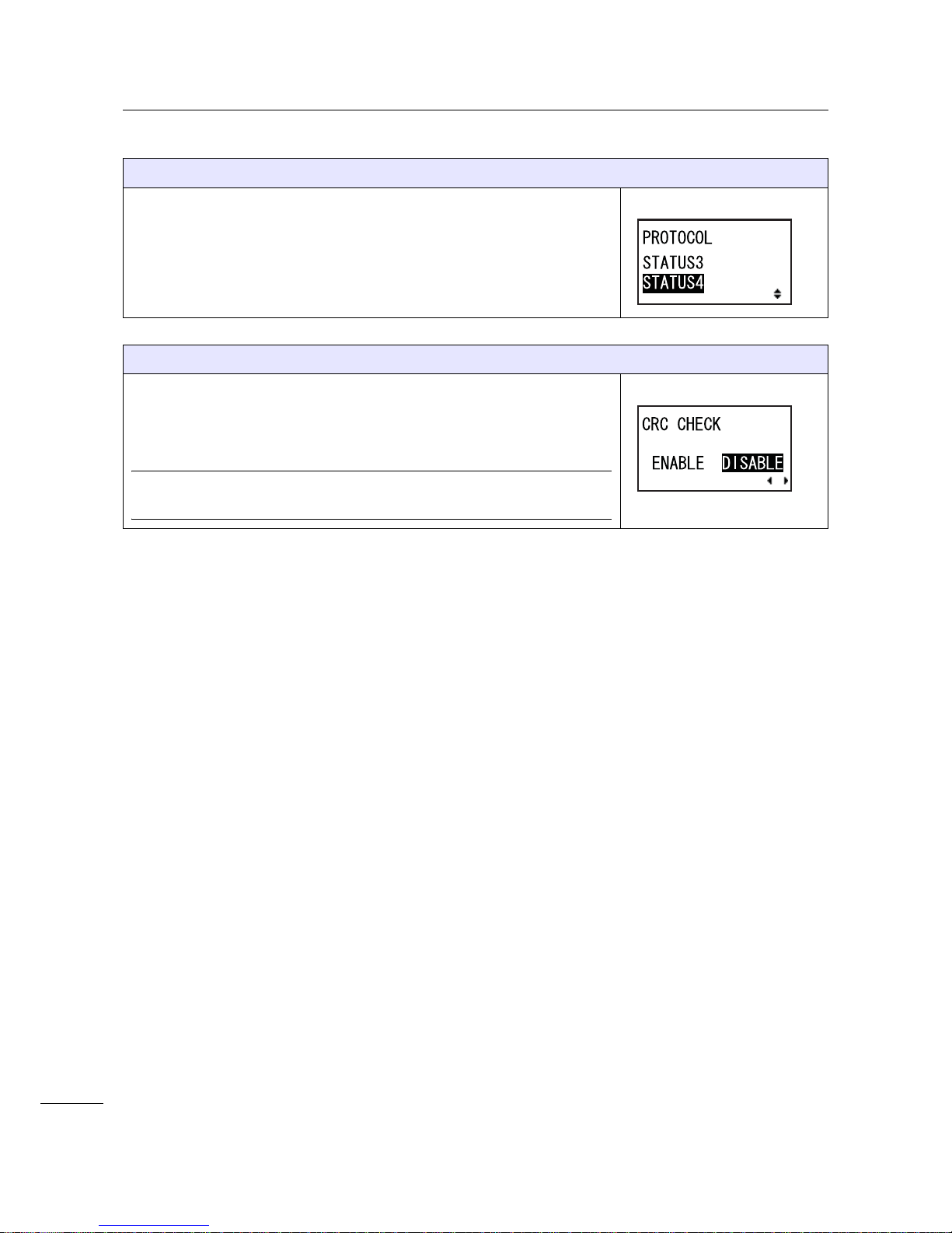
4 Operation and Configuration
96
S84-ex/S86-ex Operator Manual
PROTOCOL
Set the communication protocol.
The following options are available:
•STATUS3
•STATUS4
CRC CHECK
Set the CRC check function.
• ENABLE: Enable the CRC check function.
• DISABLE: Disable the CRC check function.
Note
Shows only if the Bluetooth interface is selected.
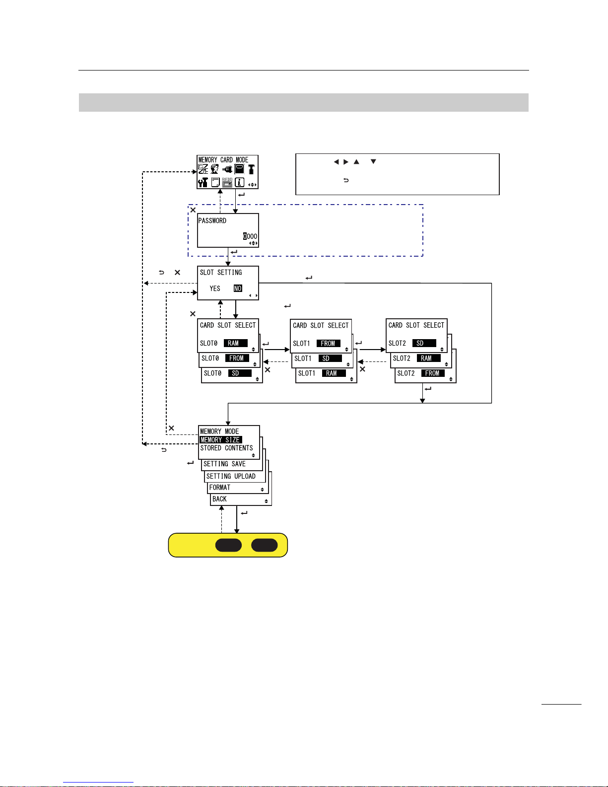
4 Operation and Configuration
97
S84-ex/S86-ex Operator Manual
4.2.1 1
Memory Mode
The flowchart shows the sequence of the setting screens for the memory mode. The table describes
each setting screen in detail.
Shows only when the
PASSWORD input is enabled
Select “NO” +
button
button
button
button
button
button
Select “YES” +
or
button
button
or select
BACK +
button
button
button
button
button
Proceed to or .
M-A M-B
* Press the , , or button to select an item or set the value
accordingly. The active arrow icons are shown on the screen.
* Pressing the button on each screen will revert to the MEMORY
CARD MODE menu.
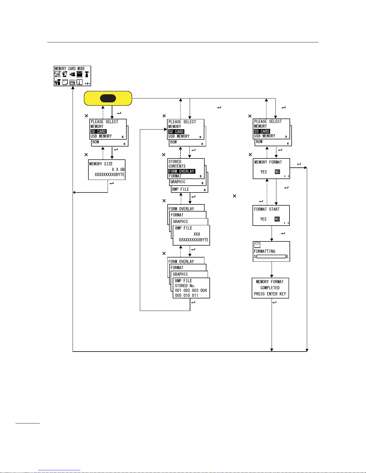
4 Operation and Configuration
98
S84-ex/S86-ex Operator Manual
button
button
button
button
button
Select “STORED
CONTENT” + button
button
Select “FORMAT”
+ button
button
button
button
button
button
button
button
button
Select “YES”
+
Select “NO” +
button or
Select “NO”
+
Select “YES”
+
button button
Select “MEMORY SIZE”
+ button
M-A
 Loading...