

“i” PROGRAMMING REFERENCE
For printer models:
MB200i / MB400i / MB410i
www.satoamerica.com
PN: 9001158(B)

SATO America, Inc.
10350A Nations Ford Road
Charlotte, NC 28273
Main Phone: (704) 644.1650
Technical Support: (704) 644.1660
Technical Support Fax: (704) 644.1661
E-Mail: satosales@satoamerica.com
techsupport@satoamerica.com
www.satoamerica.com
© Copyright 2009 SATO America, Inc. All rights reserved
PN: 9001158B

TABLE OF CONTENTS
INTRODUCTION
About This Manual 1-2
Print Area Calculation 1-3
PROGRAMMING CONCEPTS
Programming Language 2-2
Selecting Protocol Codes 2-3
Using Basic 2-4
Print Position Commands 2-5
COMMAND CODE QUICK REFERENCE
A: <ESC>A Start Label 3-2
<ESC>A1 Media Size 3-2
<ESC>&R Form Overlay, Recall 3-2
<ESC>&S Form Overlay, Store 3-2
<ESC>* Clear (Memory Card) 3-2
<ESC>@ Offline/Pause 3-2
<ESC>A3 Start Point Correction 3-2
B: <ESC>B Barcode, Ratio 1:3 3-3
<ESC>BC CODE 93 Barcode 3-3
<ESC>BD Barcode, Ratio 2:5 3-3
<ESC>BG CODE 128 Barcode 3-3
<ESC>BP Postnet 3-3
<ESC>BU Buzzer Activation 3-4
C: <ESC>CS Print Speed 3-4
D: <ESC>D Barcode, Ratio 1:2 3-4
<ESC>d Barcode, Human Readable Information (HRI) 3-4
E: <ESC>EU EAN/UCC Composite Symbol 3-4
F: <ESC>F Sequential Numbering 3-4
<ESC>FW Printing, Lines & Boxes 3-4
G: <ESC>G Graphics, Custom 3-5
<ESC>GC BMP File, Recall 3-5
<ESC>GI Graphic, Store 3-5
<ESC>GM Graphics, BMP File 3-5
<ESC>GR Graphic, Recall 3-5
<ESC>GT BMP File, Store 3-5
H: <ESC>H Horizontal Print Position 3-5
I: <ESC>ID Job Store ID 3-5
<ESC>IG Sensor Type Selection 3-6
<ESC>I1 Serial Interface, Configuration 3-6
<ESC>I2 IrDA Interface, Configuration 3-6
<ESC>I3 IrDA Interface, Device Name Configuration 3-6
<ESC>I6 Pin Code, Configuration 3-6
<ESC>I7 Authentication Mode, Configuration 3-6
<ESC>I8 Device Name, Configuration 3-6
J: <ESC>J Journal Printing 3-6
K:
<ESC>L Character, Expansion 3-6
L:
M:
N:
<ESC>OA OCR-A Font 3-6
O:
<ESC>OB OCR-B Font 3-6
P: <ESC>P Character, Pitch 3-6
<ESC>#E Print Darkness 3-6
<ESC>% Rotate, Fixed Base Reference Point 3-7
<ESC>PG EEPROM Setup 3-7
<ESC>PM Print Mode Selection 3-7
<ESC>PO Offset 3-7
<ESC>PR Character, Fixed Spacing 3-7
<ESC>PS Character, Proportional Spacing 3-7
Q: <ESC>Q Print Quantity 3-7
“i” Programming Reference PN: 9001158B

<ESC>QS System Priority 3-7
R: <ESC>RD CG Fonts 3-7
<ESC>RF Recall and Print of Font & Logo 3-7
S:
<ESC>T External Character 3-8
T:
<ESC>2D10/15 PDF417 3-8
<ESC>2D12 Micro PDF417 3-8
<ESC>2D20 Maxi Code 3-9
<ESC>2D30 QR Code (Model 2) 3-9
<ESC>2D31 QR Code (Model 1) 3-10
<ESC>2D32 Micro QR Code 3-10
<ESC>2D50 Data Matrix Code (ECC200) 3-11
<ESC>2S Two-Color Print 3-11
U:
V:
<ESC>V Vertical Print Position 3-11
W: <ESC>WC EAP Authentification Specification 3-11
<ESC>WD Copy Image Area (Partial Copy) 3-11
<ESC>WE Password Specification 3-11
<ESC>WF Secret Key Specification 3-11
<ESC>WG Socket Port Number Settings 3-11
<ESC>WH User Name Specification 3-11
<ESC>WI IP Setup Method Specification 3-12
<ESC>W1 IP Address 3-12
<ESC>W2 Subnet Maskings 3-12
<ESC>W3 Default Gateway Specification 3-12
<ESC>W4 SSID Settings 3-12
<ESC>W5 Channel Specification 3-12
<ESC>W6 WLAN Specification 3-12
<ESC>W7 Security Function Specification 3-12
<ESC>W8 WEP Key Specification 3-12
<ESC>W9 Authentication Specification 3-12
X: <ESC>XB XB Font 3-12
<ESC>XL XL Font 3-13
<ESC>XM XM Font 3-13
<ESC>XS XS Font 3-13
<ESC>XU XU Font 3-13
Y: <ESC>YR Format, Recall 3-13
<ESC>YS Format, Store 3-13
Z: <ESC>Z Stop Label 3-13
<ESC>z0 Page Break 3-13
<ESC>0 Replace Data (Partial Edit) 3-13
STANDARD COMMAND CODES
Control Commands 4-2
<ESC>A Start Label 4-2
<ESC>Z Stop Label 4-2
<ESC>Q Print Quantity 4-3
<ESC>ID Job ID Store 4-4
<ESC>z0 Page Break 4-5
Modification Commands 4-7
<ESC>L Character, Expansion 4-7
<ESC>P Character, Pitch 4-8
<ESC>PR Character, Fixed Spacing 4-9
<ESC>PS Character, Proportional Spacing 4-9
<ESC>% Rotate, Fixed Base Reference Point 4-10
<ESC>F Sequential Numbering 4-11
<ESC>FW Print, Lines & Boxes 4-12
<ESC>0 Replace Data (Partial Edit) 4-13
<ESC>WD Copy Image Area (Partial Copy) 4-14
<ESC>J Journal Printing 4-15
<ESC>RF Recall and Print of Font & Logo 4-16
Print Position Commands 4-17
<ESC>A1 Media Size 4-17
<ESC>H Horizontal Print Position 4-18
<ESC>V Vertical Print Position 4-18
Font Commands 4-19
“i” Programming Reference PN: 9001158B

<ESC>XB XB Font 4-19
<ESC>XL XL Font 4-19
<ESC>XM XM Font 4-19
<ESC>XS XS Font 4-19
<ESC>XU XU Font 4-19
<ESC>OA OCR-A Font 4-19
<ESC>OB OCR-B Font 4-19
<ESC>RD CG Fonts 4-20
<ESC>T External Character 4-23
<ESC>XB Smoothing 4-24
<ESC>XL Smoothing 4-24
Barcode Commands 4-25
<ESC>B Barcode, Ratio 1:3 4-25
<ESC>BD Barcode, Ratio 2:5 4-25
<ESC>D Barcode, Ratio 1:2 4-25
<ESC>d Barcode, Human Readable Information (HRI) 4-27
<ESC>BC CODE 93 Barcode 4-28
<ESC>BG CODE 128 Barcode 4-29
<ESC>BP Postnet 4-30
<ESC>EU EAN/UCC Composite Symbol 4-31
2D Code Commands 4-33
<ESC>2D10 PDF417 4-33
<ESC>2D12 Micro PDF417 4-34
<ESC>2D20 Maxi Code 4-35
<ESC>2D30 QR Code (Model 2) 4-36
<ESC>2D31 QR Code (Model 1) 4-36
<ESC>2D32 Micro QR Code 4-38
<ESC>2D50 Data Matrix (ECC200) 4-39
System Commands 4-40
<ESC>BU Buzzer Activation 4-40
<ESC>CS Print Speed 4-41
<ESC>#E Print Darkness 4-42
<ESC>2S 2-Color Pint Range 4-43
<ESC>A3 Base Reference Point 4-44
<ESC>PO Offset 4-45
<ESC>@ Offline/Pause 4-46
<ESC>PG EEPROM Setup 4-47
<ESC>I1 Serial Interface, Configuration 4-48
<ESC>I2 IrDA Interface, Configuration 4-49
<ESC>I3 IrDA Interface, Device Name Configuration 4-50
<ESC>IG Sensor Type Selection 4-51
<ESC>PM Print Mode Selection 4-52
<ESC>QS System Priority 4-53
Graphic Commands 4-54
<ESC>G Graphics, Custom 4-54
<ESC>GM Graphics, BMP File 4-55
Memory Store/Recall Commands 4-56
<ESC>&S Form Overlay, Store 4-56
<ESC>&R Form Overlay, Recall 4-58
<ESC>YS Format, Store 4-59
<ESC>YR Format, Recall 4-60
<ESC>GI Graphic, Store 4-61
<ESC>GR Graphic, Recall 4-62
<ESC>GT Graphic, BMP File Store 4-63
<ESC>GC Graphic, BMP File Recall 4-64
<ESC>* Clear 4-65
OPTIONAL COMMAND CODES
Bluetooth Commands 5-2
<ESC>I6 Pin Code, Configuration 5-2
<ESC>I7 Authentification Mode, Configuration 5-3
<ESC>I8 Device Name, Configuration 5-4
WLAN Commands 5-5
<ESC>WC EAP Authentication Specification 5-5
<ESC>WE Password Specification 5-6
<ESC>WF Secret Key Specification 5-7
“i” Programming Reference PN: 9001158B

<ESC>WG Socket Port Number Settings 5-8
<ESC>WH User Name Specification 5-9
<ESC>WI IP Setup Method Specification 5-10
<ESC>W1 IP Address 5-11
<ESC>W2 Subnet Maskings 5-12
<ESC>W3 Default Gateway Specification 5-13
<ESC>W4 SSID Settings 5-14
<ESC>W5 Channel Specification 5-15
<ESC>W6 WLAN Specification 5-16
<ESC>W7 Security Function Specification 5-17
<ESC>W8 WEP Key Specification 5-18
<ESC>W9 Authentication Specification 5-19
BI-DIRECTIONAL COMMUNICATIONS
Introduction 6-2
General Configuration 6-2
Serial Interface 6-2
Receive Buffer 6-2
Data Transmission 6-2
Return Status 6-3
Enquire & Response 6-5
Enquire (ENQ) 6-5
Cancel (CAN) 6-5
Print Job 6-5
Printer Status (MG) 6-5
Sensor Status (SG) 6-7
Format Overlay Status (FO) 6-7
Interface Status (IG) 6-8
Battery Information (BI) 6-8
System Version Information (SB) 6-9
Memory Status (EB) 6-9
APPENDIX
Custom Graphics 7-2
Custom Graphics Example 7-2
PCX Graphics Example 7-5
Printer Configuration Commands 7-6
Reference Tables 7-8
Table 1: Character Font Set (<ESC>XU) 7-8
Table 2: Character Font Set (<ESC>XS) 7-9
Table 3: Character Font Set (<ESC>XM) 7-10
Table 4: Character Font Set (<ESC>XB) 7-11
Table 5: Character Font Set (<ESC>XL) 7-12
Table 6: Character Font Set (<ESC>OA) 7-13
Table 7: Character Font Set (<ESC>OB) 7-14
Table 8: Barcode Type (<ESC>B) 7-15
Table 9: Barcode Type (<ESC>BD) 7-16
Table 10: Barcode Type (<ESC>D) 7-17
Table 11: Character Font Set (<ESC>BC) 7-18
Table 12: CODE128 Data Values (<ESC>BG) 7-19
Table 13: Character Font Set (<ESC>2D10) 7-21
Table 14: Barcode Type (<ESC>2D12) 7-22
Table 15: Character Font Set (<ESC>2D12) 7-23
Table 16: Character Font Set (<ESC>2D20) 7-24
Table 17: Code128 Data Values (<ESC>2D30) 7-25
Table 18: Code128 Data Values (<ESC>2D31) 7-26
Table 19: Character Font Set (<ESC>2D32) 7-27
Table 20: Character Font Set (<ESC>2D32) 7-28
Table 21: Character Font Set (<ESC>2D32) 7-29
Table 22: Character Font Set (<ESC>2D50) 7-30
Table 23: Parameters (<ESC>PG) 7-31
“i” Programming Reference PN: 9001158B

Unit 1: Introduction
INTRODUCTION
• About This Manual
• Print Area Calculation
“i” Programming Reference
1-1 PN: 9001158B

Unit 1: Introduction
ABOUT THIS MANUAL
This manual is laid out consistent with the product discussed and provides all of the information required for printer
programming.
This manual also incorporates the use of special information boxes. Examples of these boxes and the type of
information provided in each, are below.
WARNING: PROVIDES INFORMATION THAT, IF UNHEEDED, MAY RESULT IN
PRESONAL INJURY.
CAUTION: PROVIDES INFORMATION THAT, IF UNHEEDED, MAY
RESULT IN EQUIPMENT DAMAGE.
ATTENTION: Provides information that is deemed of special importance but
will not result in personal injusry or product damage if unheeded.
NOTE: Provides helpful hints to assist in performing the tasks at hand.
LCD DISPLAY: Provides the specific display that should be visible on the LCD at that
point.
A comprehensive Table Of Contents provided at the front of this manual facilitates rapid movement within. The
contents identify the different Units, Chapters, and Sections. Each references the page number of their
commencement.
The pages of this manual have embedded headers and footers to assist the user in identifying his or her exact
position within the manual. The header provides the unit number followed by its name. The footer identifies the
product on the left, the manual’s part number in the center, and the page number to the right side of the page.
Page enumeration is two-part with each separated by a hyphen. The first character set references the Unit and the
second identifies the page number. Page numbers begin with the numeral (1) one at the commencement of a new
unit and ascends sequentially.
“i” Programming Reference
1-2 PN: 9001158B

Unit 1: Introduction
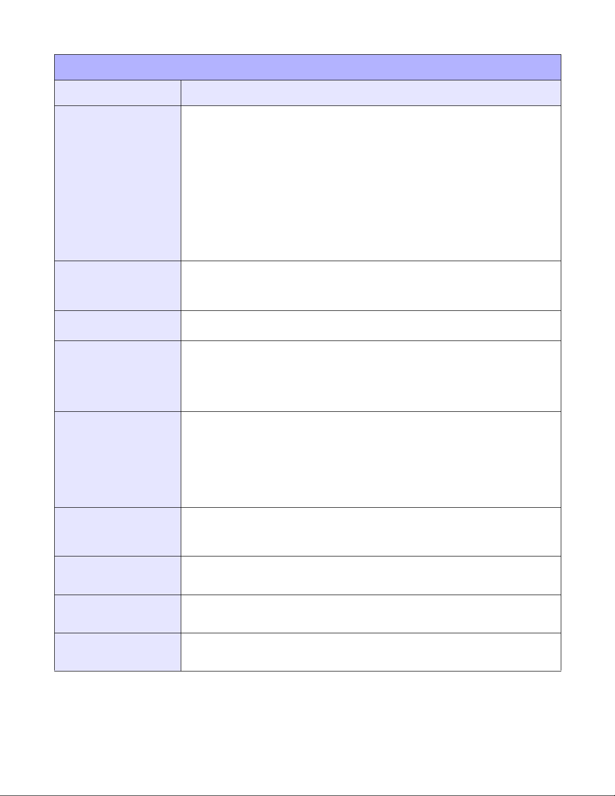
PRINT AREA CALCULATION
Many print applications may not require labels that fill the entire printable area of the printer. Therefore it is
important to understand how to calculate print size so that the printed image does not exceed the label size.
There are two axis to consider when calculating for print position; horizontal and vertical. The horizontal axis is
lateral positioning parallel with the print head and is measured from the right side of the media to the left. The
vertical axis is the label length from the front to its rear.
This juncture point of the horizontal and vertical axis is referred to as the Base Reference Point (or zero point) and
all measurement is incremental along those axis from there. The allowable ranges for these references are
dependent on the particular printer to accommodate different print widths and resolutions.
A1 COMMAND
The A1 command is the prefered method of configuring the printer for media size. If using media smaller than the
print head width, use this command to specify the media size and adjust the start position corresponding to that.
The backing paper must be included in media size considerations. This command would be as follows:
<A1>aaaaabbbb
a = Height of Label
b = Width of Label
NOTE: The valid ranges for each of the above may be found in the product
manuals.
A3 COMMAND
Before beginning to send code, one must perform some simple calculations to determine print positioning. Firstly,
determine the print resolution and maximum print width of the printer. This information is provided in the Technical
Data unit of the Operator Manual and Service Manuals.
The print resolution of the print head has a direct bearing on the “dots per inch” (DPI) of print density. The
corresponding formula for a 203 Resolution print head on a printer with 4.1 Maximum Print Width would be:
Resolution (DPI) x Maximum Printable Width (Linear Inches) =
Maximum Printable Width (Linear Dots)
203 (DPI) x 4.1 (Linear Inches) = 832 (Linear Dots)
Once this is done, one must calculate the label width in linear dots. That formula would be as follows for a 2 inch
wide label:
Resolution (DPI) x Label Width (Linear Inches) =
Label Width (Linear Dots)
203 (DPI) x 2.0 (Linear Inches) = 406 (Linear Dots)
Lastly, one must calculate the horizontal distance to offset printing to accommodate the difference in size from the
printer’s maximum printable width to the label width. That formula would be as follows using the above examples:
Maximum Printable Width (Linear Dots) - Label Width (Linear Dots) =
Print Offset (Linear Dots)
832 (Linear Dots) - 406 (Linear Dots) = 426 (Linear Dots)
In the above example, 426 would be the required command entry to reset the initial base reference point (or zero
point) to the new base reference point (or zero point) based on the label’s width.
Note that with each additional horizontal or vertical adjustment, the New Base Reference Point will always be
positioned relative to the last base reference point - not the Initial Base Reference Point. In other words, the only
way to return to the Initial Base Reference Point is to ensure that you send commands that represent your desired
reference point.
“i” Programming Reference
1-3 PN: 9001158B
Unit 1: Introduction
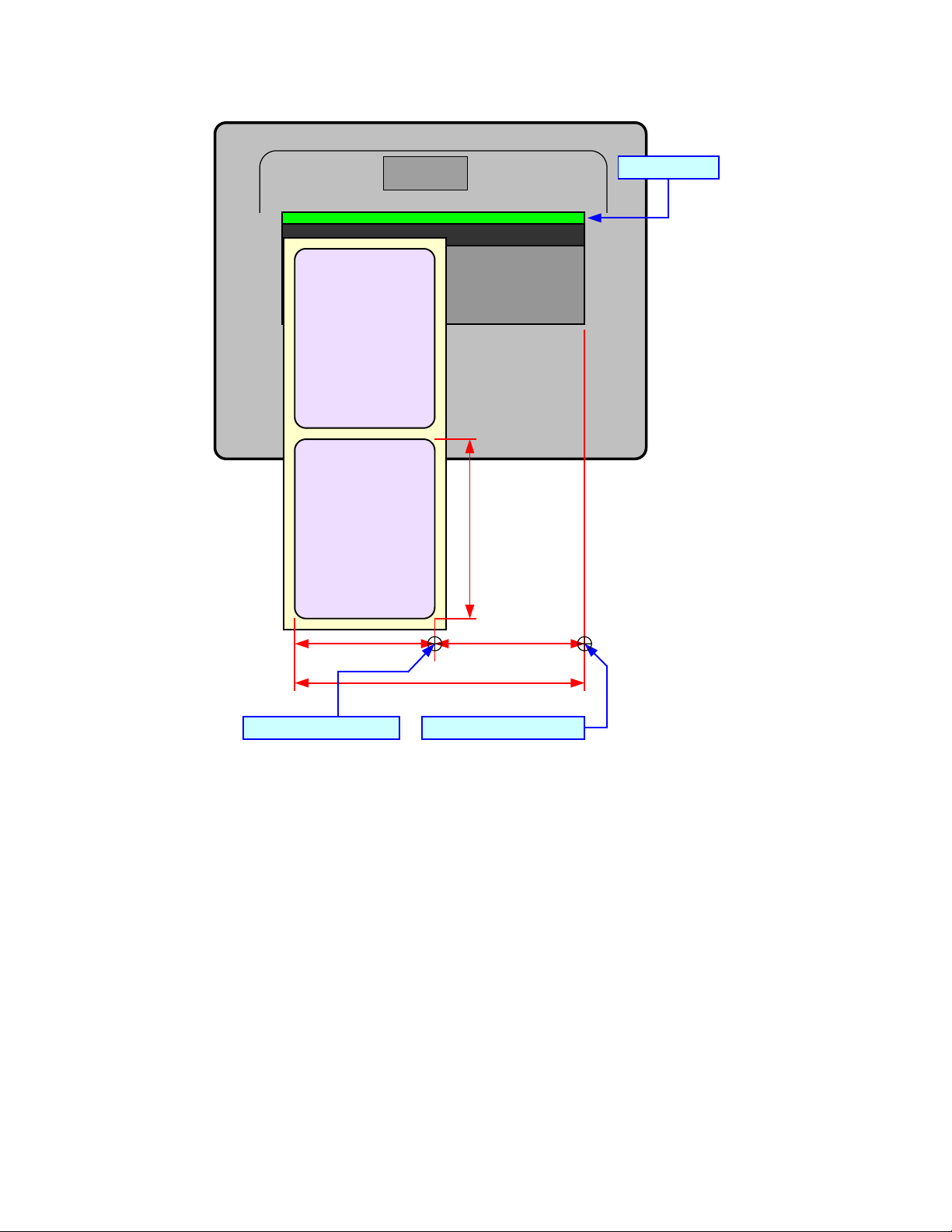
Print Head
LABEL
LABEL
Label Width
Label Length
Maximum Printable Width
Initial Base Reference Point
Print Offset
New Base Reference Point
Figure 1-1, Print Area Calculation
“i” Programming Reference
1-4 PN: 9001158B

Unit 2: Programming Concepts
PROGRAMMING
CONCEPTS
• Programming Language
• Selecting Protocol Codes
• Using Basic
• Print Position Commands
i Programming Reference
2-1 PN: 9001158B

Unit 2: Programming Concepts
PROGRAMMING LANGUAGE
A programming language for a printer is a familiar concept to most programmers. It is a group of commands that
are designed to use the internal intelligence of the printer. The commands, which are referred to as SATO
Command Codes, contain non-printable ASCII characters (such as <STX>, <ETX>, <ESC>) and printable
characters. These commands must be assembled into an organized block of code to be sent as one data stream to
the printer, which in turn interprets the command codes and generates the desired label output. The programmer is
free to use any programming language available to send the desired data to the printer.
The printer command codes used are based upon “Escape” (1B hexadecimal) sequences. Typically there are four
types of command sequences:
<ESC>{Command}
These commands generally tell the printer to perform a specific action, like “clear the memory.”
<ESC>{Command} {Data}
Commands with this format tell the printer to perform a specific action which is dependent upon the following data,
like “print X labels”, where the value for X is contained in the data.
<ESC>{Command} {Parameter}
These commands set the operational parameters of the printer, like “set the print speed to 3.”
<ESC>{Command} {Parameter} {Data}
Some commands can contain both Parameter and Data elements, such as “print a Code 39 symbol containing the
data.”
i Programming Reference
2-2 PN: 9001158B
Unit 2: Programming Concepts
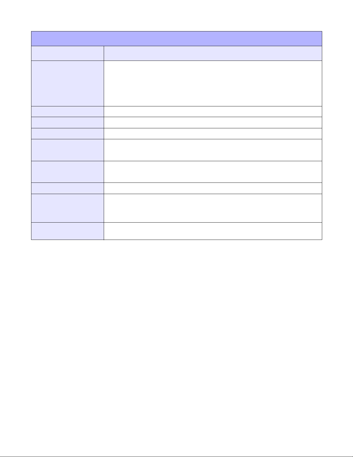
SELECTING PROTOCOL CODES
Protocol codes are the special control characters that prepare the printer to receive instructions. For example, the
<ESC> character tells the printer that a command code will follow and the <ENQ> character asks for the printer
status.
There are two pre-defined different sets of Protocol Control codes to choose from. Each set is made up of six
special characters. The Standard Protocol Control codes are non-printable characters, and the Non-Standard
Protocol Control codes are printable characters. The Non-Standard set may be useful on host computers using
protocol converters or in an application where non-printable ASCII characters cannot be sent from the host.
This manual uses the Standard Protocol Control codes for all of the
examples. Alternately, the user may define and download a set of custom
Protocol Control Codes (see Appendix D).
PROTOCOL CODES
CONTROL
CHARACTER
STX 02 Hex 7B Hex = { Data start
ETX 03 Hex 7D Hex = } Data end
ESC 1B Hex 5E Hex = ^ Command Code to follow
ENQ 05 Hex 40 Hex = @ Get printer status, Bi-Com Mode
CAN 18 Hex 21 Hex = ! Cancel print job, Bi-Com mode
Off-Line 40 Hex 5D Hex = ] Take printer Off-Line
STANDARD
DSW2-7 OFF
NON-STANDARD
DSW2-7 ON
DESCRIPTION
i Programming Reference
2-3 PN: 9001158B

Unit 2: Programming Concepts
USING BASIC
It may be useful to test your printer using a BASIC program on a PC or to write your actual production programs in
BASIC. Whatever the reason, if working in BASIC, some of the following hints may be helpful.
Set the WIDTH of the output device to 255 characters to avoid automatically sending <CR> and <LF> characters
after every line. The command string should be continuous and uninterrupted by <CR> and/or <LF> commands.
The examples given in this manual are printed on separate lines because they will not fit on a single line and do not
contain <CR> and/or <LF> characters. If these characters are needed, they are explicitly noted by the inclusion of
<CR> and <LF> notations.
If using the printer’s RS232C interface, it is necessary to set the computer COM port on so the CTS and DSR
signals are ignored. Send OPEN “COM” statements as follows:
OPEN “COM1:9600,E,8,1,CS,DS”AS #1
This sets the host computer’s COM1 port RS232C communication parameters for 9600 baud, Even parity, 8 Data
bits, 1 Stop bit and directs the port to ignore the CTS and DSR control signals.
It may be desirable to assign the <ESC> character to a string variable to reduce keystrokes since this character is
often used.
The following example uses Standard Protocol codes in BASIC.
PRINTING WITH THE RS232C PORT
5 REM Parallel Example Identifies the program as a printer RS232C port print label.
The “REM” prevents this data from being sent to the
printer and displays it only on the screen.
10 E$=CHR$(27) Sets the“E$”string as an <ESC>character.
OPEN “COM1:9600,N,8,1,CS,DS”AS #1 Opens the COM1 port for output and sets the parameters
as 9600 baud, No parity, 8 Data bits, 1 Stop bit and
instructs the port to ignore the CTS and DSR control
signals.
30 PRINT #1,CHR$ (2); Sends an <STX> (ASCII Code a decimal “2”) to the printer
instructing it to prepare to receive a message.
50 PRINT #1,E$;"A"; Sends an “<ESC>A” command code to Print Port #1
opened by statement 20 above.
60 PRINT#1, E$; "H400"; E$; "V100"; E$;
"XL1SATO"
50 PRINT #1, E$;"Q1"; Instructs the printer to print a quantity of one label.
60 PRINT #1, E$; “Z”; Informs the printer that the last command has been sent
Sends the data “SATO” to be placed 400 dots horizontally
and 100 dots vertically on the label and printed in the“XL”
autosmoothed font.
and printing can occur.
70 PRINT #1,CHR$ (3); Sends an <ETX> (ASCII Code decimal “3”) informs the
printer of message end.
Identifies the program as a printer RS232C port print label.
The “REM” prevents this data from being sent to the
printer and displays it only on the screen.
i Programming Reference
2-4 PN: 9001158B
Unit 2: Programming Concepts
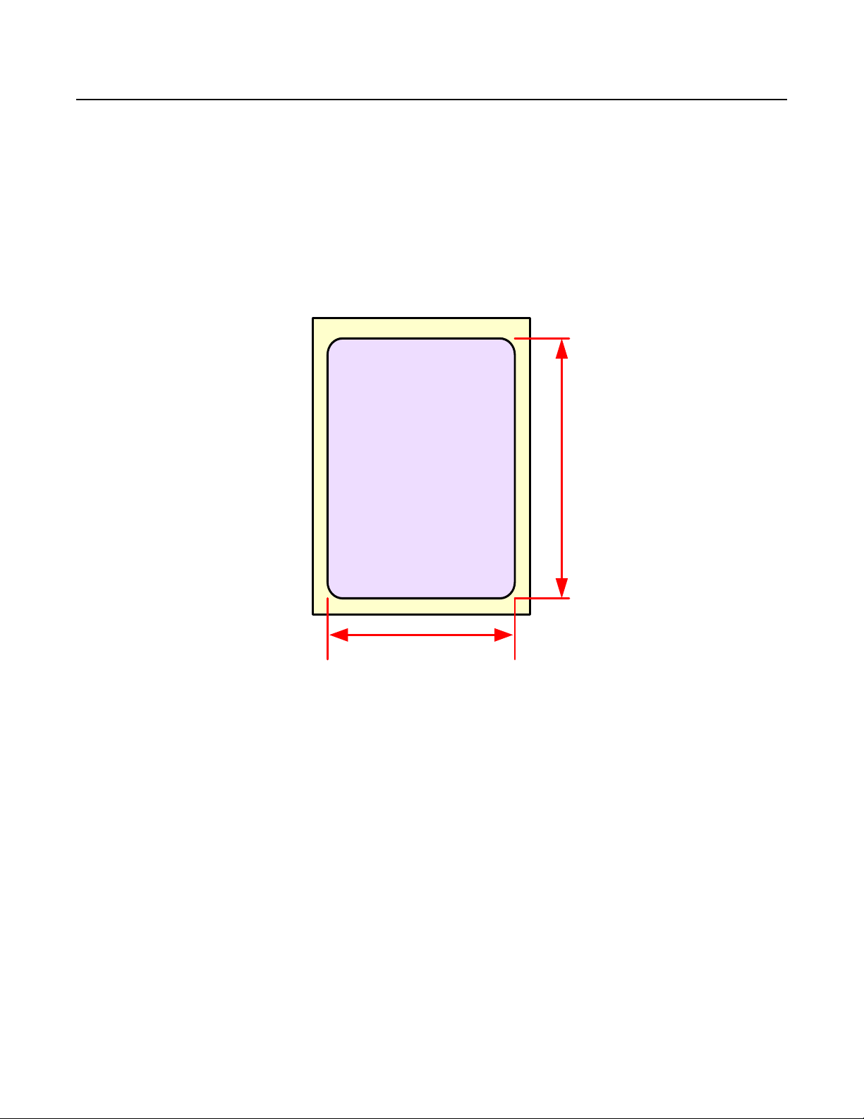
LABEL
Label Width
Label Length
PRINT POSITION COMMANDS
There are three methods using command codes to properly orient print images on a label. They are as follows:
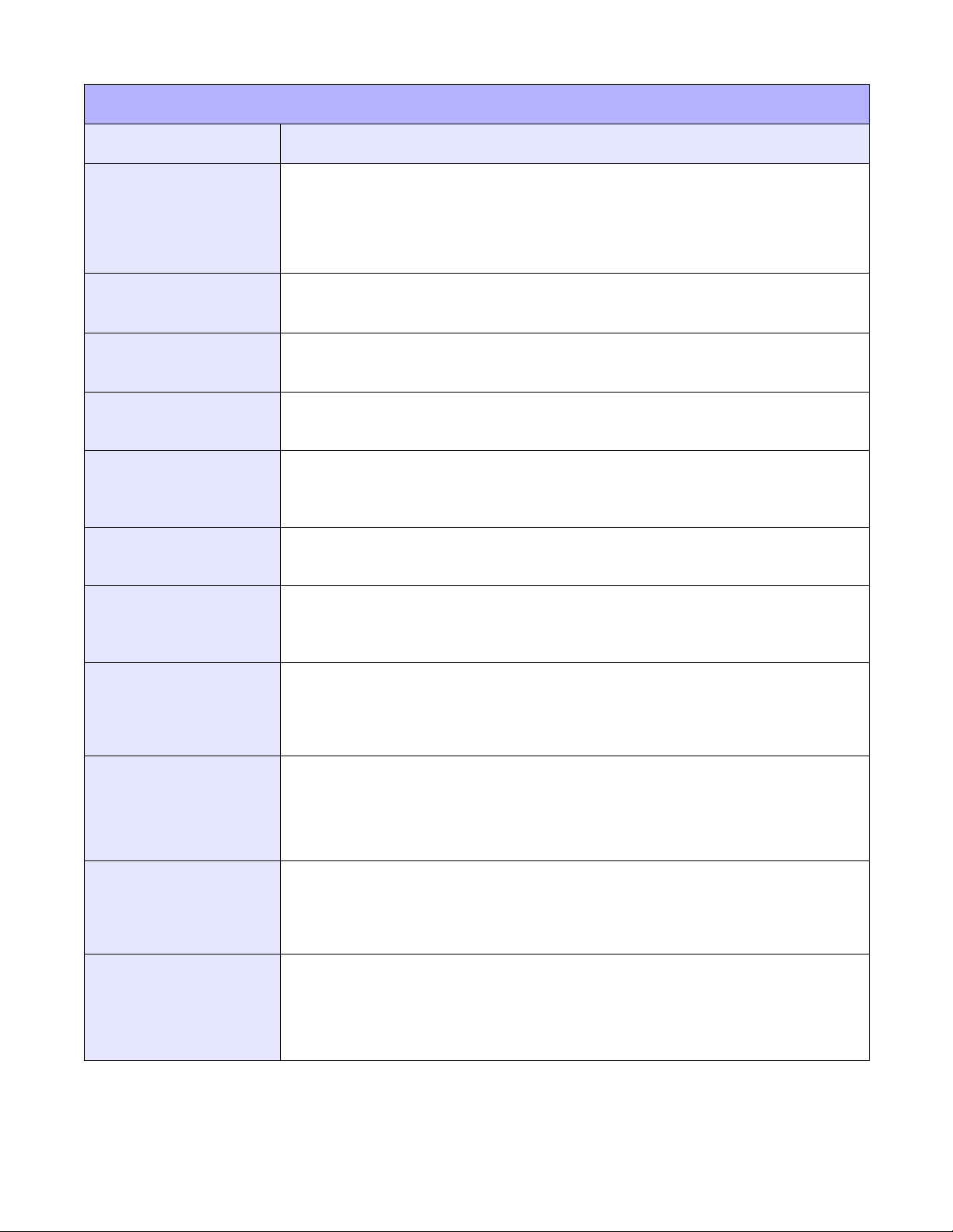
MEDIA SIZE COMMAND
The Media Size Command (<ESC>A1) allows specification of the label width and length so the printer may
autmatically adjust itself relative to the command entry. However, the label size specified and the actual label size
must match.
EXAMPLE: <ESC>A1aaaaabbbb
a = Label Length
b = Label Width
Figure 2-1, Media Measurement
BASE REFERENCE POINT COMMAND
The Base Reference Point Command (<ESC>A3) establishes the zero point of the Horizontal and Vertical axis so
the distance may be calculated in dots from that point to the label’s edge. This command immediately follows the
Data Start Command.
EXAMPLE: Label Width = total dots - = 406 dots
New Base Ref Point = Max Print Width - Label Width
= (dot quantity) - (406 dots) = 426 dots
Issue Base Reference Point command <ESC>A3 after the data Start command.
<ESC>A<ESC>A3H0426V0001. . . . . .
i Programming Reference
2-5 PN: 9001158B

Unit 2: Programming Concepts
HORIZONTAL OFFSET COMMAND
Allows print image orientation by combining a part of both methods above by establishing the media size and then
orienting it through base reference point adjustment.
EXAMPLE: A Printer with 8-dpmm:
Label Width = 2" x 25.4 mm/in x 8 dpmm = 406 dots
New Base Reference Point = Maximum Print Width - Label Width
= (832 dots) - (406 dots) = 426 dots
Each <ESC>H command would have the value “426” added to it to correctly position each field.
NOTE: The <ESC>A3 Base Reference Point command can also shift the
reference point in a negative direction (toward the outside edge of the label).
The Command Code subsection contains a sample label output for each command code. These samples reflect
how the printed information would appear on a 4.25 inch wide label.
If you want to test any of the sample label outputs and are using labels less than five inches in width, it is
recommended that the Base Reference Point command be added to the data stream to print the image onto the
label.
The addition of the Base Reference Point command to the data stream will help adjust the print. See the following
two examples or refer to the Base Reference Point command description.
EXAMPLE: <ESC>A
<ESC>H0050<ESC>V0100<ESC>L0303<ESC>XMSATO
<ESC>H0050<ESC>V0200<ESC>B103100*SATO*
<ESC>H0070<ESC>V0310<ESC>L0101<ESC>XUSATO
<ESC>Q1<ESC>Z
If using a 2 inch wide label, the entire image may not appear on the label. By adding the following Base Reference
Point command to the second line of the data stream, the base reference point will be changed, causing the image
to shift toward the inside of the printer where it can be printed on the narrower label.
EXAMPLE: Data stream results in a 2 inch wide label:
<ESC>A
<ESC>A3H0406V0001
<ESC>H0050<ESC>V0100<ESC>L0303<ESC>XMSATO
<ESC>H0050<ESC>V0200<ESC>B103100*SATO*
<ESC>H0170<ESC>V0310<ESC>L0101<ESC>XUSATO
<ESC>Q1
<ESC>Z
The image is moved horizontally to the right 2 inches (406 dots) so that itcan be printed on a 2 inch wide label. For
more information, see the Base Reference Point command description.
i Programming Reference
2-6 PN: 9001158B

Unit 3: Code Quick Reference
COMMAND QUICK
REFERENCE
• A through Z (all commands)
“i” Programming Reference
3-1 PN: 9001158B
Unit 3: Code Quick Reference
COMMAND QUICK REFERENCE
INSTRUCTION DESCRIPTION
A Start Code. Begins all print jobs
A1aaaabbbb Media Size. Specifies the label size.
aaaa = Label height in dots (0 to Vmax)
bbbb = Label width in dots (0 to Hmax)
&R Form Overlay, Recall. Recalls a label image previously stored in expanded memory.
aa
= Storage number (00 to 99)
&S,aa,bbbb,cccc Form Overlay, Store. Stores a label image in Expanded Memory.
aa = Storage number (00 to 99)‘
bbbb = Horizontal size of window to be stored (50 to Hmax)
cccc = Vertical size of window to be stored (50 to Vmax)
A(space)Z Form Feed. Feeds a blank tag or label.
*a,bbb Clear Memory Card. Clears data stored on memory card.
a = Memory section to be cleared.
G: SATO graphics file (001 to 999)
F: Stored formats (001 to 999)
R: BMP graphic file (001 to 999)
bbb = Storage location to clear (001 to 999)
@,nn...n Offline/Pause. Signals the printer to go offline after upon job completion.
nn...n = Applicable only on models with an LCD. Message to be displayed
(maximum 32 characters).
A3H-aaaa-Vbbbb Base Reference Point. Establishes a new base reference point position for the current
label. Units of measurement are dots.
- = Optional character.If included, will shift reference point in negative
direction.
aaaa = Horizontal reference point
bbbb = Vertical reference point
“i” Programming Reference
3-2 PN: 9001158B
Unit 3: Code Quick Reference
COMMAND QUICK REFERENCE
INSTRUCTION DESCRIPTION
Babbcccd Bar Codes. Prints a 1:3 ratio barcode.
a = 0: Codabar
1: Code 39
2: Interleaved 2 of 5 (I 2/5)
3: UPC-A/EAN-13
4: EAN-8
5: Industrial 2 of 5
7: reserved
8: reserved
9: reserved
B: reserved
C: Code 93
D: reserved
E: UPC-E
G: Code 128
H: SSCC
bb = Number of dots (01 to 12) for narrow bar and narrow space
ccc = Bar height in dots (001 to 999)
d = SSCC only
0: No human readable text
1: Human readable at top
2: Human readable at bottom
BC CODE 93 Barcode. Prints a CODE 93 barcode.
a = Narrow bar width (01 to 12 dots)
b = Height of barcode (001 to 999 dots)
c = Digit quantity of data (01 to 99)
n = Print data
BDabbcccd Bar Codes. Prints a 2:5 ratio barcode, except for UPC, EAN, Code 93, Code 128 and SSCC
symbols, which are fixed width bar codes. For values a, bb, ccc and d see instructions for
Babbcccd.
For UPC/EAN bar codes, this command puts descender bars and humand readable text
below the symbol.
BG CODE 128. Prints a CODE 128 barcode.
a = Narrow bar width (01 to 12 dots)
b = Height of barcode (001 to 999 dots)
n = Print data
BPn...n Postnet. Prints Postnet bar codes.
n...n = 5 digit ZIP (Postnet-32 format)
6 digits (Postnet-37 format)
9 digit ZIP+4 (Postnet -52 format)
11 digit ZIP+4+DPC (Postnet-62, Delivery Point format).
“i” Programming Reference
3-3 PN: 9001158B
Unit 3: Code Quick Reference
COMMAND QUICK REFERENCE
INSTRUCTION DESCRIPTION
BU Buzzer Activation. Activate/Deactivate buzzer. This command can be used only on an MB4i
printer.
a = 0: deactivated
1: activated
CSa Print Speed Selection. Specifies a unique print speed in in./sec. through software for a
particular label.
a = Speed Range
Dabbcccn Barcode, Human Readable Information (HRI). Specifies the character type of human
readable information of barcode.
a = 3: JAN/EAN13
4: JAN/EAN8
H: UPC-A
b = Narrow bar width (01 to 12 dots)
c = Barcode height (001 to 999 dots)
n = Barcode print data
dn...n Barcode, Human Readable Information (HRI). Specifies the character type of human
readable information of barcode. May be used in conjunction with the preceding <ESC>D.
d = Character type specification
XU
XS
XM
XB
XL
OA
OB
HRI data
n = HRI print data
EU Expanded Print Length. Expands the print length to 9999 dots.
Faaaabcccc ddee Sequential Numbering. Allows the printing of sequencing fields (text, bar codes) where all
incrementing is done within the printer.
aaaa = Number of times to repeat the same data (0001 to 9999).
b = Plus or minus symbol (+ for increments; - for decrements).
cccc = Value of step for sequence (001 to 9999).
dd = Quantity of digits for sequential numbering (01 to 99).
ee = Quantity of digits free for sequential numbering (01 to 99).
FWaabcccc Line. Prints a line. Units of measurement are dots.
aa = Width of line
b = V: Vertical line
H: Horizontal line
cccc = Length of line
“i” Programming Reference
3-4 PN: 9001158B
Unit 3: Code Quick Reference
COMMAND QUICK REFERENCE
INSTRUCTION DESCRIPTION
FWaabbVcccHdddd Box. Prints a box. For values aa, bbbb, cc, and dddd, see instructions for horizontal and
vertical lines. Units of measurement are dots.
aa = Width of horizontal side
bb = Width of vertical side
cccc = Length of vertical side
dddd = Length of horizontal side
Gabbbccc(data) Custom Graphics. Allows the creation and printing of graphic images using a dot-
addressable matrix.
a = Specifies format of data stream to follow
B: Binary
H: Hexadecimal
bbb = Number of horizontal 8 x 8 blocks
ccc = Number of vertical 8 x 8 blocks
data = Data to describe the graphic image
GCaaa BMP File, Recall. Recalls BMP graphic files stored in Expanded Memory.
GIabbbcccdddee...e Graphic, Store. Stores a graphic image in the memory card to be called later for printing on
a label.
a = Specifies format of data stream to follow
B: Binary
H: Hexadecimal
bbb = Number of horizontal 8 x 8 blocks
ccc = Number of vertical 8 x 8 blocks
ddd = Graphics storage number (001 to 999)
ee...e = Data to describe the graphic image
GMaaaaa BMP File. Prints BMP file to the internal graphics image memory.
aaaaa = Quantity of bytes to download (max DOS file size is 32K).
GRccc Graphic, Recall. Recalls for printing the graphic image stored by the GI command.
ccc = Storage number (001 to 999)
GTaaa,bbbbb, nn. . . n BMP File, Store. Stores BMP files in Expanded Memory.
aaa = Storage area number (001 to 999)
bbbbb = Size of BMP file in bytes
nn....n = Data
Haaaa Horizontal Position. Specifies a fieldís horizontal location across the width of the label from
the current base reference point. The units of measurement are dots.
IDaa Job ID Store. Stores the Job ID number.
aa = Job ID number assigned (01 to 99)
“i” Programming Reference
3-5 PN: 9001158B
Unit 3: Code Quick Reference
COMMAND QUICK REFERENCE
INSTRUCTION DESCRIPTION
IGa Sensor Type Selection. Selects the sensor type.
a = 0: Reflective (Eye-Mark) sensor.
1: Transmissive (See-Thru) sensor
2: Sensor not used
I1 Serial Interface, Configuration. Sets the operating parameters for the Serial RS232C
interface. Sets the default printer configuration in Flash ROM. Refer to the System Command
chapter of the Standard Command Code unit for details.
I2 IrDA Interface, Configuration. Sets the operating parameters for the Serial RS232C
interface. Sets the default printer configuration in Flash ROM. Refer to the System Command
chapter of the Standard Command Code unit for details.
I3 IrDA Interface, Device Name Settings. Allows specification of the device name.
aa = Alphanumeric (1 to 16)
I6 Bluetooth Interface, PIN Code Specification. Allows specification of a PIN code.
aa = ASCII characters other than control codes 20H to 7EH (01 to 16)
I7 Bluetooth Interface, Authentication Mode Settings. Specifies parameters relative to
search and connectivity.
a = 0: No authentication
1: Level 2-1 authentication
2: Level 2-2 authentication
3: Level 3 authentication
b = ISI validity: 0015 to 1000 (4 digit fixed, hexadecimal)
c = ISW validity: 0012 to 0997 (4 digit fixed, hexadecimal)
d = PSI validity: 0015 to 1000 (4 digit fixed, hexadecimal)
e = PSW validity: 0012 to 0997 (4 digit fixed, hexadecimal)
I8 Bluetooth Interface, Device Name Settings. Allows specification of the device name.
aa = ASCII characters other than control codes 20H to 7EH (01 to 20)
J Journal Print. Provides the ability to print text line by line. Fixed spacing between lines and
characters.
Laabb Character, Expansion. Expands characters in both directions.
aa = Multiple to expand horizontally (01 to 12)
bb = Multiple to expand vertically (01 to 12)
OA Font type. Specifies the OCR-A font.
OB Font type. Specifies the OCR-B font dot matrix.
Paa Character Pitch. Designates the number of dots between characters.
aa = Number of dots between characters (01 to 99)
#Ea Print Darkness. Specifies a new print darkness setting.
“i” Programming Reference
3-6 PN: 9001158B
Unit 3: Code Quick Reference
COMMAND QUICK REFERENCE
INSTRUCTION DESCRIPTION
%a Rotate, Fixed Base Reference Point.
a = 0: Sets print to normal direction.
1: Sets print to 90 degrees counter-clockwise.
2: Sets print to 180 degrees rotated (upside down)
3: Sets print to 270 degrees counter-clockwise (90x CW).
PG EEPROM Setup. Sets the default printer configuration in EEPROM.
PMa Print Mode Selection. Selects desired backfeed operation.
a = 0: No backfeed, continuous operation
1: Tear-Off
PR Fixed Font Spacing. Returns the printer to fixed character spacing mode.
PS Proportional Font Spacing. Places the printer in the proportional character spacing mode.
Will not work with U Font.
Qaaaaaa Print Quantity. Specifies the total number of labels to print.
aaaaaa = Total quantity of labels to print for the job (000001-999999)
QS
RD
RF Recall and Print of Font & Logo. Calls and prints font and logo downloaded with Label
System Priority. Priority setting to System / Command. This command is available only on
MB4i series.
a = 0 : Priority assigned to command
1 : Priority assigned to system setting
CG Fonts. Specifies Agfa CGFont (only available on MB4i Series).
a (Font Type) = A (CG Times)
b (Style) = 00 Fixed pitch
c (Character width) = 004-999 in dots
or P02-P99 in points
d (Character height) = 004-999 in dots
or P02-P99
n (Data to print) = Data
Gallery’s “GalleryMemMaster”.
a = Font ID number (01 to 99)
b = Print digit (1 to 9999)
n = Print data
“i” Programming Reference
3-7 PN: 9001158B
Unit 3: Code Quick Reference
COMMAND QUICK REFERENCE
INSTRUCTION DESCRIPTION
T
2D10
External Character. Specifies to download external character.
a [External Character type] = 1:16x16 (Ascii Code Specification) (Single-
digit Specification)
2:24x24
3:22x22
b [Number of Font Registration] = 01-95 (Ascii Code Specification)
(Double-digit Specification)
c [External Character Code] = 21(H) - 7F(H) (Binary Code Specification)
d [External Character Font Data]= 16x16: 32 Bytes
24x24: 72 Bytes
22x22: 66 Bytes
PDF417. Specifies PDF417 of 2D code.
a = Minimum module width in dots (01 to 09)
b = Minimum module height in dots (01 to 24)
c = Security level (0 to 8)
d = Quantity of data code words per line (01 to 30)
e = Quantity of lines per symbol (03 to 90)
f = Code type
0: Normal/Omissible
1: Truncated
2D12
Micro PDF417. Specifies Micro PDF417 of 2D code.
a = Minimum module width in dots (01 to 09)
b = Minimum module height in dots (01 to 24)
c = Quantity of data code words per line (1 to 4)
d = Quantity of lines per symbol (2)
e = Binary mode
0: Normal/Omissible
1: Binary Mode
m = Quantity of data bytes for binary mode (0001 to 0366)
n = Print data
“i” Programming Reference
3-8 PN: 9001158B

Unit 3: Code Quick Reference
COMMAND QUICK REFERENCE
INSTRUCTION DESCRIPTION
2D20
2D30
Maxi Code. Specifies Maxi Code of 2D code.
a = Mode
2: Delivery only (numeric only)
3: Delivery only (alphanumeric only)
4: Standard Symbol
6: Reader only
b = Service class in numeric (001 to 999)
c = Country code in numeric (001 to 999)
d = Postal code
Mode 2: Maximum of 9 numeric digits (0 to 999999999)
Mode 3: Maximum of 6 alphanumeric (000000 to 999999)
m = Quantity of print data (1 to 138)
n = Data (00H is not designable)
QR Code (Model 2). Specifies QR code (model 2) of 2D code.
a = Error correction level
L: 7%
M: 15%
Q: 25%
H: 30%
b = Size of one side of cell in dots (01 to 32)
c = Data setting mode
0: Manual setting
1: Automatic setting (print data specification will differ)
d = Concatenation mode
0: Normal mode
1: Concatenation mode
e = Quantity of partitions by concatenation (01 to 16)
f = Sequential number partitioned by concatenation (01 to 16)
g = Concatenation mode Parity data in Hex character (00 to FF)
k = Enter mode
1: Numeric mode
2: Alphanumeric mode
m = Quantity of data (1 to 2953)
n = Print data
“i” Programming Reference
3-9 PN: 9001158B
Unit 3: Code Quick Reference
COMMAND QUICK REFERENCE
INSTRUCTION DESCRIPTION
2D31
QR Code (Model 1). Specifies QR code (model 1) of 2D code.
a = Error correction level
L: 7%
M: 15%
Q: 25%
H: 30%
b = Size of one side of cell in dots (01 to 32)
c = Data setting mode
0: Manual setting
1: Automatic setting (print data specification will differ)
d = Concatenation mode
0: Normal mode
1: Concatenation mode
e = Quantity of partitions by concatenation (01 to 16)
f = Sequential number partitioned by concatenation (01 to 16)
g = Concatenation mode Parity data in Hex character (00 to FF)
k = Enter mode
1: Numeric mode
2: Alphanumeric mode
m = Quantity of data (1 to 486)
2D32
n = Print data
Micro QR Code. Specifies Micro QR code of 2D code.
a = Error correction level
L: 7%
M: 15%
Q: 25%
b = Size of one side of cell in dots (01 to 32)
c = Data setting mode
0: Manual setting
1: Automatic setting
k = Enter mode
1: Numeric mode
2: Alphanumeric mode
m = Quantity of data (1 to 486)
n = Print data
“i” Programming Reference
3-10 PN: 9001158B
Unit 3: Code Quick Reference
COMMAND QUICK REFERENCE
INSTRUCTION DESCRIPTION
2D50
2S
Vbbbb Vertical Posi tion. Specifies a field’s vertical location down the length of the label from the
WC Wireless LAN, EAP Authentification Specification. Specifies EAP.
Data Matrix (ECC200). Specifies Data Matrix (ECC200) of 2D code.
a = Cell width in dots (01 to 16)
b = Cell height in dots (01 to 16)
c = Quantity of cells per roll (000, fixed)
d = Quantity of cell rows (000, fixed)
m = Quantity of binary data (1 to 3116)
n = Print data
7EH, 00H: when printing 00H
7EH, 7EH: when printing 7EH
Two-Color Printing. Specifies printing in two colors - black and red.
a = 0: Black print
1: Red print
current base reference point. Units of measurement are dots.
a = 0: Not used
1: EAP-MD5
2: EAP-TLS
4: EAP-PEAP
WDHaaaaVbbbbXccccYddddCopy Image Area (Partial Copy). To copy an image to another location of the label.
aaaa = Horizontal position of the top left corner of image area
bbbb = Vertical position of the top left corner of image area
cccc = Horizontal length of image area
dddd = Vertical length of image area
WE Wireless LAN Interface, Password Specification. Allows specification of an authorization
password.
a = Up to 32 characters possible.
WF Wireless LAN Interface, Secret Key Specification. Specifies the secret key.
a = Valid from 0 to 32 characters.
WG Wireless LAN Interface, Socket Port Number Settings. Specifies the socket port number.
aaaa = Four digit numeral fixed.
WH
Wireless LAN Interface, User Specification. Specifies username authentification.
a = Valid from 1 to 63 characters.
“i” Programming Reference
3-11 PN: 9001158B
Unit 3: Code Quick Reference
COMMAND QUICK REFERENCE
INSTRUCTION DESCRIPTION
WI
W1
W2
W3
W4
W5
W6
Wireless LAN Interface, IP Setup Method. Allows specification of the IP address setup
method.
a = Address settings:
0: Manual setting
1: DHCP
Wireless LAN Interface, IP Address Settings. Permits setup of the IP address.
a = Decimals up to 12 places.
Wireless LAN Interface, Subnet Mask Setup. Permits setup of the subnet mask.
a = Decimals up to 12 places.
Wireless LAN Interface, Default Gateway Specification. Specifies the default gateway.
a = Decimals up to 12 places.
Wireless LAN Interface, SSID Settings. Specifies the settings for SSID.
a = Alphabets along with a hyphen (-), an underscore (_) can be specified up
to 32 characters.
Wireless LAN Interface, Channel Specification. Allows specification of the channel used.
a = 01 to 14 digits, fixed.
Wireless LAN Interface, Mode Specification. Permits the specification of the WLAN mode.
a = 1: Adhoc Mode
2: Infrastructure Mode
W7
W8
W9
XBa Font Type. Specifies 48W x 48L dot matrix font (includes descenders).
Wireless LAN Interface, Security Function Specification. Specifies mode of encoding.
a = 0: Not set
1: WEP encoding used
2: WPA encoding used
Wireless LAN Interface, WEP Key Specification. Specifies the WEP key.
a = A: ASCII
B: HEX
b = WEP key: ASCII (5 or 13 characters), HEX (10 or 26 characters)
Wireless LAN Interface, Authentification Specification. Specifies the authentification
function.
a = 0: WPA-PSK
1: EAP
a = 0: Disables auto-smoothing of font
1: Enables auto-smoothing if expansion is greater than 3.
n = Print data
“i” Programming Reference
3-12 PN: 9001158B
Unit 3: Code Quick Reference
COMMAND QUICK REFERENCE
INSTRUCTION DESCRIPTION
XL Font Type. Specifies the 48W x 48H dot matrix font (includes descenders).
a = Smooting specificaiton
0: Smoothing disabled
1: Smoothing enabled
n = Print data
XM Font type. Specifies the 24W x 24H dot matrix font (includes descenders).
XS Font type. Specifies the 17W x 17H dot matrix font (includes descenders).
XU Font type. Specifies the 5W x 9L dot matrix font (includes descenders).
YR,aaa Recall Format. To recall a field from a format previously stored in the memory card.
aaa = Number of format to be recalled (001 to 999)
YS,aaa Store Format. To store a field in a format in the memory card.
aaa = Format number (001 -999)
Z Stop Code. Ends all print jobs.
z0 Page Break. In Journal printing mode (mode 2), helps printer’s buffer handle the data “page
by page,” not an entire chunk.
a
0 (zero) Replace Data (Partial Edit). Provides the ability to replace a specified area of the previous
label with new data.
(Page break position) = Length of a page in dots (omissible).
“i” Programming Reference
3-13 PN: 9001158B

Unit 3: Code Quick Reference
“i” Programming Reference
3-14 PN: 9001158B
 Loading...