

Page 1
MB200i
Printer
SERVICE MANUAL
PN 9001145B
Page 2

SATO America, Inc.
10350A Nations Ford Road
Charlotte, NC 28273
Main Phone: (704) 644.1650
Technical Support Hotline: (704) 644.1660
Technical Support Fax: (707) 644.1661
E-Mail: satosales@satoamerica.com
techsupport@satoamerica.com
www.satoamerica.com
WARNING
THE EQUIPMENT REFERENCED IN THIS DOCUMENT COMPLIES WITH THE REQUIREMENTS IN
PART 15 OF FCC RULES FOR A CLASS B COMPUTING DEVICE. OPERATION OF THIS EQUIPMENT
IN A RESIDENTIAL AREA MAY CAUSE UNACCEPTABLE INTERFERENCE TO RADIO AND TV
RECEPTION.
Page 3

TABLE OF CONTENTS
INTRODUCTION
About This Manual 1-2
General Description 1-3
Theory Of Operation 1-3
Switches & Indicators 1-4
TECHNICAL DATA
Physical Characteristics 2-2
Enviromental 2-2
Power 2-2
Processing 2-2
Sensing 2-2
Regulatory Approvals 2-2
Print 2-3
Interface Modules 2-3
Media 2-3
Character Font Capabilities 2-3
Barcode Capabilities 2-4
INTERFACE SPECIFICATIONS
Interface Specifications 3-2
802.11B Wireless 3-3
RS232 Serial Interface 3-4
Infrared Rays (IrDA) 3-5
Bluetooth 3-7
All Interface Types 3-8
Receive Buffer 3-8
ACK/NAK Protocol 3-8
AD-HOC Connectivity 3-9
MB200i Wireless LAN Configuration Tool 3-9
MB200i Driver 3-9
Printer Setup 3-9
Computer Setup 3-12
LCD DISPLAY
Display Fields 4-2
Battery Level 4-2
Wireless Field Strength 4-3
Operational Status 4-3
LCD Screens 4-4
Startup 4-4
Normal Mode 4-4
Test Print Mode 4-4
Default Setting Mode 4-5
Factory Clear Mode 4-5
Hex Dump Mode 4-5
Printer Errors 4-6
Maintenance Mode 4-7
LCD Setup 4-7
Wireless LAN 4-8
PN 9001145B
Page 4

PRINTER CONFIGURATION
Printer Configuration 5-2
Factory Defaults 5-2
RS232C Quick Reference Table 5-2
IRDA Quick Reference Table 5-2
Bluetooth Quick Reference Table 5-3
Wireless LAN Quick Reference Table 5-3
Configuration Modes 5-4
Normal Mode 5-4
Label Sensor Selection 5-5
Dispense Mode 5-6
Download Mode 5-7
Font Download Mode 5-9
Online Command Mode 5-11
CRC (Cyclic Redundancy Check) Mode 5-12
Sleep & Auto-Off Mode 5-13
TROUBLESHOOTING
Error Signals 6-2
Troubleshooting Table 6-3
Interface Troubleshooting 6-4
RS232 Serial Interface 6-4
LAN Ethernet Interface 6-4
Test Print Troubleshooting 6-6
Hex Dump Mode 6-6
Test Label Printing 6-7
REPLACEMENT PROCEDURES
Print Head 7-2
Dispense Bar 7-3
Platen Roller 7-5
Dispenser Roller 7-6
Main Circuit Board (A) 7-7
Main Circuit Board (B) 7-8
Panel & LCD Board 7-9
Eye-Mark Sensor 7-10
Gap Sensor 7-12
Cover Open Sensor 7-13
Drive Gear 7-15
Drive Motor 7-16
ADJUSTMENT PROCEDURES
Pitch Adjustment 8-2
Print Darkness 8-3
Default Setting 8-4
Factory Clear 8-5
CHARTS & DIAGRAMS
Cover Removal Diagram (A) 9-2
Cover Removal Diagram (B) 9-3
PN 9001145B
Page 5

INTRODUCTION
• About This Manual
• General Description
• Theory Of Operation
• Switches & Indicators
SATO MB2i Service Manual PN 9001145B Page 1-1
Page 6

Unit 1: Introduction
ABOUT THIS MANUAL
This manual is laid out consistent with the product discussed and provides all of the information
required for general printer configuration, troubleshooting, and maintenance. For specialized
programming, refer to the Programming Manual located on the utility CD-ROM.
Step-by-step maintenance instructions are provided with typical problems and solutions. It is
recommended that you become familiar with each section before installing and maintaining the
printer.
This manual also incorporates the use of special information boxes. Examples of these boxes
and the type of information provided in each, are below.
WARNING: PROVIDES INFORMATION THAT, IF UNHEEDED, MAY
RESULT IN PERSONAL INJURY.
CAUTION: PROVIDES INFORMATION THAT, IF UNHEEDED, MAY
RESULT IN EQUIPMENT DAMAGE.
NOTE: Provides helpful hints to assist in performing the tasks at hand.
A comprehensive Table Of Contents provided at the front of this manual facilitates rapid
movement within. The contents identify the different unit sections and their respective subsections. Each references the page number of their commencement.
The pages of this manual has embedded headers and footers to assist the user in identifying his
or her exact position within the manual. The header provides the section number followed by its
name. The footer identifies the product on the left, the manual’s part number in the center, and
the page number to the right side of the page.
Page inumeration is two-part with each separated by a hyphen. The first character set references
the section number and the second identifies the page number. Page numbers begin with the
numeral (1) one at the commencement of a new section and ascends sequentially.
SATO MB2i Service Manual PN 9001145B Page 1-2
Page 7
Unit 1: Introduction
GENERAL DESCRIPTION
The MB200/201i are compact, transportable printers designed for frequent, but intermittant use.
Their direct thermal print head not only allows high performance two-color printing (with special
media), but also clear barcode printing.
Their ABS housing provides a durable, impact-resistant product. An intergrated dispenser
enables application of labels upon print. Rechargeable battery packs and a DC power
transformer ensures operation anywhere, under any conditions. An automatic power off function
turns the printers off after the last print.
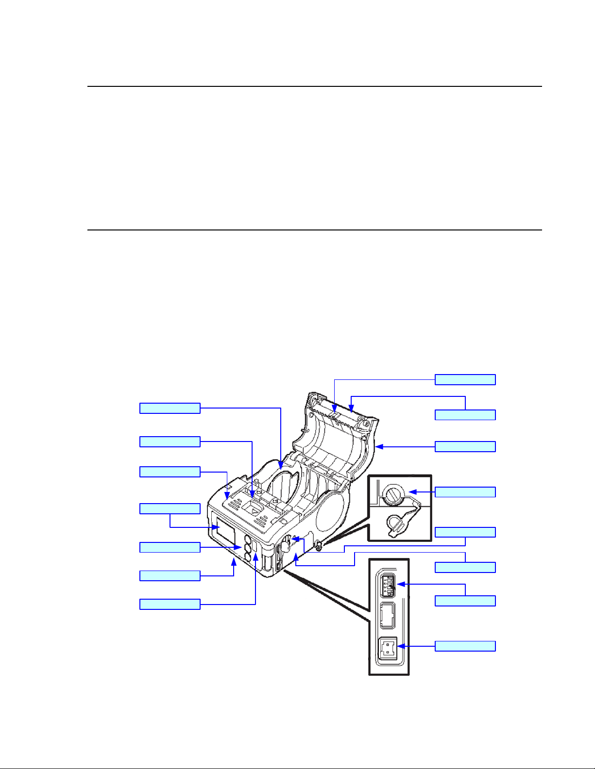
THEORY OF OPERATION
When activated, the media is fed past the print head by an integrated drive train. The drive train
is electric motor driven, coupled to a gear configuration located on the left side of the printer
chassis. Kinetic energy is transferred to a platen roller which is the driving force of media
movement. Paper guides within the chassis assembly ensure that the media remains properly
positioned during the printing process and is fed unimpeded through an opening in the front.
A series of strategically located sensors sends signals to the processing unit. The processing unit
in turn sends response signals to the various features based on programmed and received data.
Correct signals initiates print head activity.
Eye-Mark Sensor
Label Guide
Open/ Clo se Lever
Dispenser Unit
LCD Display
Function Keys
Front Housing Cover
IrDA Filter
Platen Roller
Top Housing Cover
Label Guide Dial
RS232C Port
Battery Compartment
Dip Switches
DC Power Port
Figure 1-1, Primary Features & Components
SATO MB2i Service Manual PN 9001145B Page 1-3
Page 8
Unit 1: Introduction
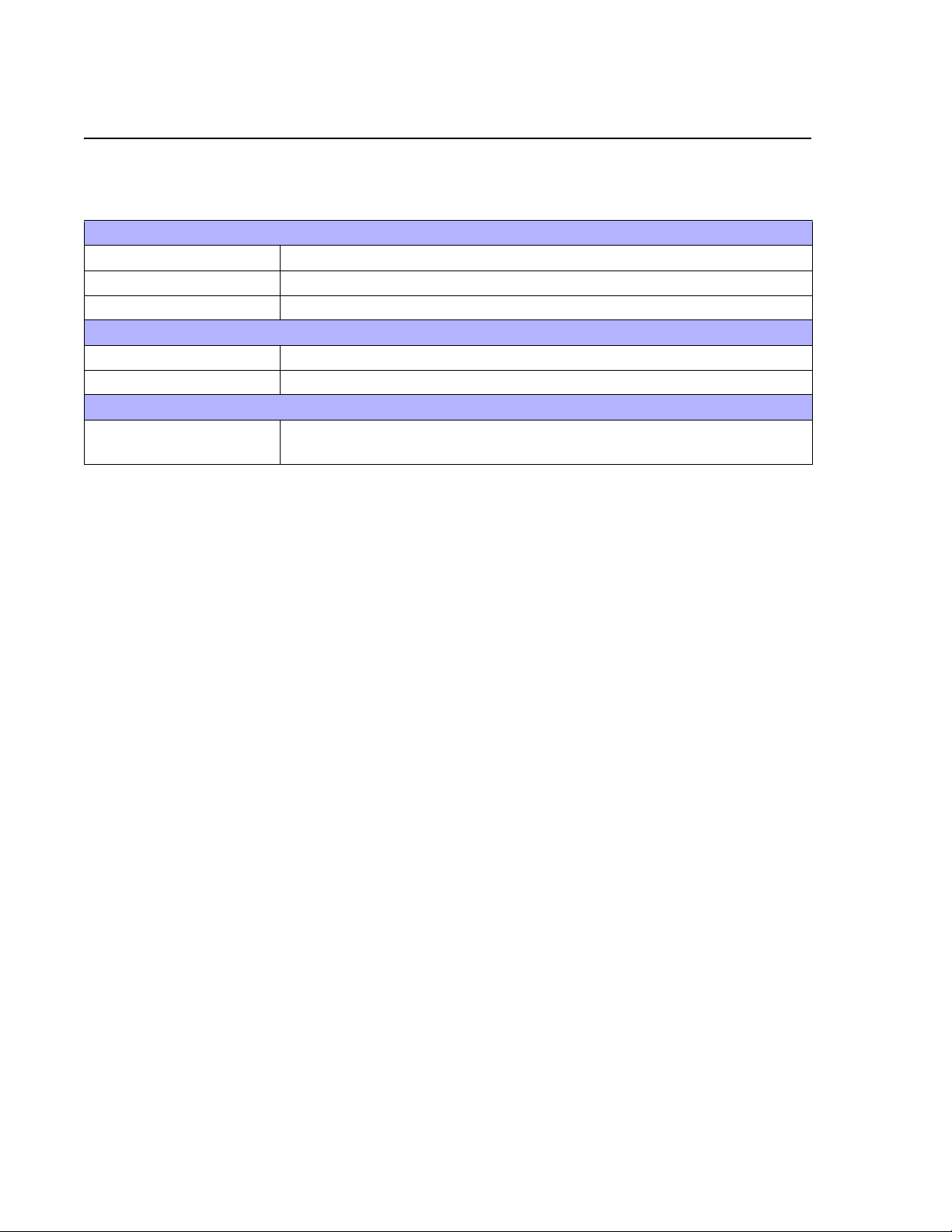
SWITCHES AND INDICATORS
The table below identifies and defines printer switches and indicators for operator interface. The
accompanying graphics display their locations and appearance
SWITCHES
Power Button Two position on/off switch that controls power flow to the system.
Print Button Two position on/off button that activates and deactivates print action.
Feed Button Two position on/off button that activates and deactivates feed action.
INDICATORS
Charge LED Indicates the resource level of the power pack.
Status LED Indicates the systems’ operational status.
DIP SWITCHES
1 through 4 Various positions of the four accumilatively decides some printer
configuration activities.
SATO MB2i Service Manual PN 9001145B Page 1-4
Page 9

TECHNICAL DATA
• Physical Characteristics
• Enviromental
•Power
• Processing
• Sensing
• Regulatory Approvals
•Print
• Interface Modules
•Media
• Character Font Capabilities
• Barcode Capabilities
SATO MB2i Service Manual PN 9001145B Page 2-1
Page 10
Unit 2: Technical Data
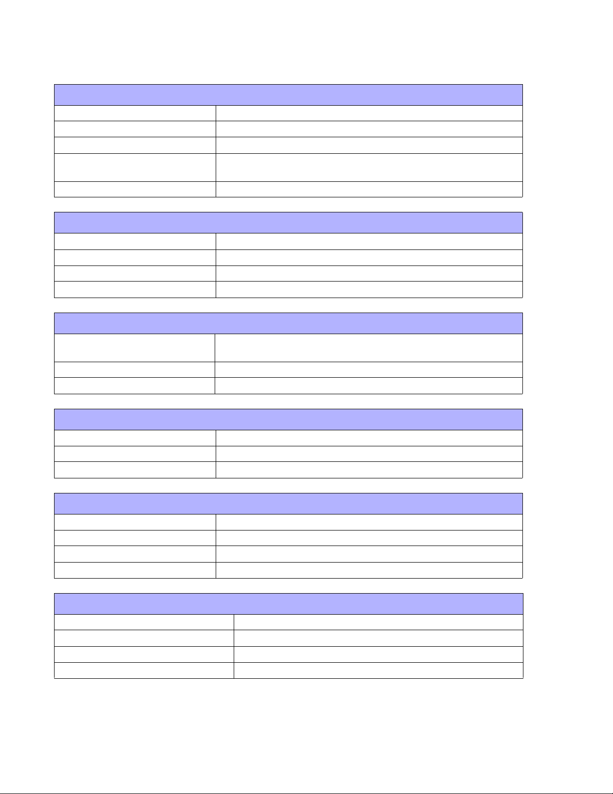
PHYSICAL CHARACTERISTICS
Height (maximum) 2.87 Inches (73 mm)
Width (maximum) 3.47 Inches (88 mm)
Depth (maximum) 5.04 Inches (128 mm)
Weight (maximum)
Drop Specification 9.84 Feet (3.0 m) all six sides
MB200i: 405 Grams (includes 105 grams for battery bag)
MB201i: 390 Grams (includes battery)
ENVIRONMENTAL
Operating Temperature 5° to 122°Fahrenheit (-15° to 50°C)
Storage Temperature -13° to 140°Fahrenheit (-25° to 60°C)
Storage Humidity 30 to 90% RH Non-Condensing
Operating Humidity 30 to 80% RH Non-Condensing
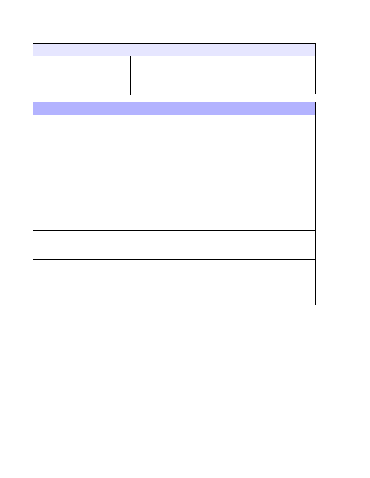
POWER
Print Capacity
Battery Lithiun ion 7.4 volts, 2400mAh standard pack
AC Adapter DC 9 Volt
Four rolls with full charge (equivalent of 48 meters). Continuous
printing is permitted (provided print duty is 16% or less).
PROCESSING
CPU 32 Bit RISC
Flash ROM 2 Megabytes
Receive Buffer 12 Kilobytes
SENSING
Gap/Dispense Fixed
Reflective Eye-Mark Fixed
Label Fixed
Head-Open Yes
REGULATORY APPROVALS
Safety UL 60950
EMC FOC, Class B
Wireless LAN R & TTE (FOC15B, FOC15C)
Bluetooth R & TTE (FOC15B, FOC15C)
SATO MB2i Service Manual PN 9001145B Page 2-2
Page 11
Unit 2: Technical Data
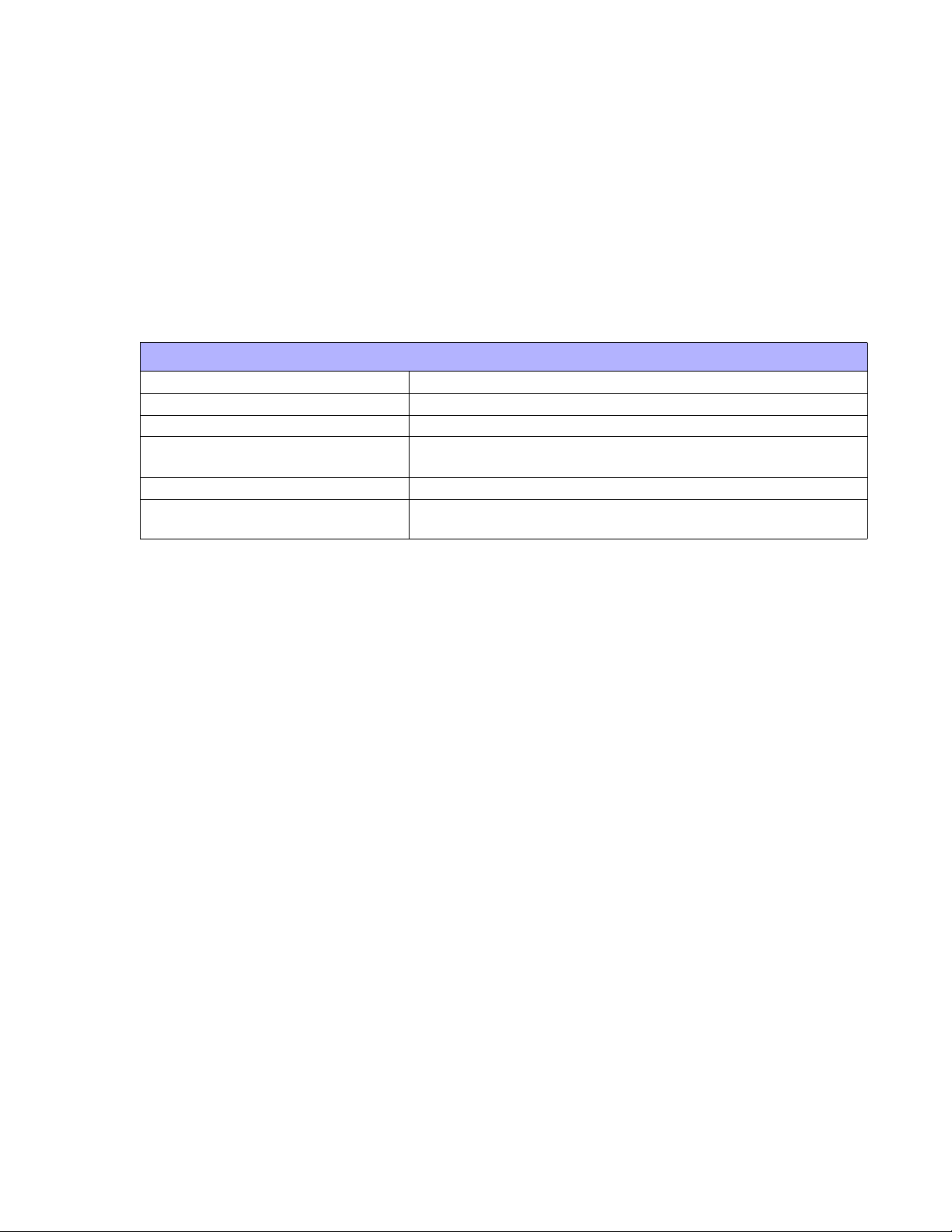
PRINT
Method Direct Thermal
Speed (maximum) 4.05 Inches Per Second (103 mm/s) (varies with print duty)
Print Module (dot size) .0049 Inches (.125 mm)
Resolution 203 Dots Per Inch (8 dpmm)
Maximum Print Width 1.89 Inches (48 mm)
Maximum Print Pitch 6.30 Inches (160 mm)
Angle 0°, 90°, 180°, 270°
INTERFACE MODULES
RS232C (9600 to 57,6000 dps) Standard
Serial Port
IrDA Ir. Std., BHT, Ir Comm (3-wire cooked), Ir Obex (optional)
Ethernet 802.11B Wireless Wi-Fi (with built-in display)
Bluetooth Version 1.1 Compliant
Ready/Busy or X-On/X-Off Flow Control
Bi-Directional Status
MEDIA
Media Types
Linerless Media Standard (strong/weak adhesive)
Media Thickness 0.0025 to 0.0075 Inches (0.064 - 0.190 mm)
Roll Media Outside Diameter 2.64 Inches (67 mm +/- 0.5) MB200i only
Wound Face In / Face Out. Face In is for linerless only.
Core Size 0.75 to 1.0 Inches ( 19.05-25.40 mm) internal diameter
Super High Sensitive, Techno-Thermal A, Sythetic Paper Thermal
C, Non-Sticky Thermal 64, Two-Color Thermal
CHARACTER FONT CAPABILITIES
MATRIX FONTS
XU Font 5 dots W x 9 dots H (Helvetica)
XS Font 17 dots W x 17 dots H (Univers Condensed Bold)
XM Font 24 dots W x 24 dots H (Univers Condensed Bold)
OA Font (OCR-A)
OB Font (OCR-B)
AUTO SMOOTHING FONTS
WB 18 dots W x 30 dots H
WL 28 dots W x 52 dots H
XB 48 dots W x 48 dots H (Univers Condensed Bold)
XL 48 dots W x 48 dots H (Sans Serif)
SATO MB2i Service Manual PN 9001145B Page 2-3
Page 12
Unit 2: Technical Data
CHARACTER CONTROL
Expansion up to 12 x in either the X or Y coordinates.
Charcter Pitch Control
Line Space Control
Journal Print facility
0, 90, 180, and 270 Degree Rotation
BAR CODE CAPABILTIES
UPC-A/E
EAN-13/8
NW-7 (Codabar)
Code 39
Linear Bar Codes
Two Dimemsional
Composite Symbology
Ratios 1:2, 1:3, 2:5, User definable bar widths
Bar Height 4 to 999 dots, User progammable
Rotation 0, 90, 180, and 270 Degrees
Sequential Numbering Sequential numbering of both numerics and bar codes
Custom Characters RAM storage for special characters
Expansion Ratio of Character Height: 1-12 times, Width: 1-12 times
Graphics
Form Overlay Form overlay for high-speed editing of complex formats
Full dot addressable graphics, SATO Hex/Binary, .BMP or
Code 93
Code 128
RSS-14
JAN/EAN
ITF
QR Code
Data Matrix
Maxicode
PDF417
.PCX formats
SATO MB2i Service Manual PN 9001145B Page 2-4
Page 13

INTERFACE
SPECIFICATIONS
• Interface Specifications
• AD-HOC Connectivity
SATO MB2i Service Manual PN 9001145B Page 3-1
Page 14

Unit 3: Interface Secifications
INTERFACE SPECIFICATIONS
This chapter presents the printer interface types and their specifications. These specifications
include detailed information to assist in the selection of the most appropriate method for the
printer to interface with the host. The acceptable interface methods are:
• 802.11B Wireless
• RS232C Serial
• Infrared Rays (IrDA)
• Bluetooth
Following the selection of the desired interface, proceed to the following unit for instructions on
how to Configure the printer for that interface type.
WARNING: NEVER CONNECT OR DISCONNECT INTERFACE CABLES
(OR USE A SWITCH BOX) WITH POWER APPLIED TO EITHER THE
HOST OR THE PRINTER. THIS MAY CAUSE DAMAGE TO THE
INTERFACE CIRCUITRY IN THE PRINTER/HOST AND IS NOT COVERED
BY WARRANTY.
SATO MB2i Service Manual PN 9001145B Page 3-2
Page 15
Unit 3: Interface Specifications
802.11B WIRELESS INTERFACE
802.11 refers to a family of specifications developed by the IEEE for wireless LAN technology to
communicate between a wireless client and a base station or between two wireless clients. This
interface only uses DSSS which allows wireless functionality comparable to Ethernet.
The wireless print server provides easy printer interface with 802.11b Wi-Fi compliant networks
free of wired connections. Each printer is shipped with a Windows driver and interface installed.
To print from a PC, the driver must be loaded and the PC must be configured to run one of the
supported protocols.
Default Parameters: DSW1, 3, 4 OFF / DSW2 ON.
802.11B WIRELESS SPECIFICATIONS
Variable Data Rates 11, 5.5, 2 and 1 Mbps
Frequency Band 2.4 GHz ISM Band
Wired Equivalent Privacy & WPA WEP 128 bit, 64 bit (compatible with 40bit), WPA, 802.11x
Sensitivity (typ, AAWGN, 8E-2 PER): -91dBm at 1Mbps, -88dBm at 2 Mdps,
-87dBm at 5.5Mbps, -84dBm at 11Mbps.
Range 100m indoors, 300m outdoors
Protocols TCP/IP, IPX/SPX, Direct Mode IPX/IP, DLC/LLC, NetBEUI,
NetBIOS/IP
SATO MB2i Service Manual PN 9001145B Page 3-3
Page 16

Unit 3: Interface Secifications
RS232C SERIAL INTERFACE
This interface is an industry standard for serially transmitting data using a wired cable. Separate
transmit and receive lines enable data to flow in both directions simultaneously. Data transmitted
using this protocol is defined in its parameters; baud/bps (speed), data bits, stop bit, parity, and
hand-shaking method. To change the parameter settings, refer to the Programming Reference
document for this product. The Programming Reference and a ready-made cable with DIN and
DB9 connectors may be acquired from SATO.
Default Parameters: DSW1-4 OFF, 19200bps, 8 data bits, 1 stop bit, no parity.
Figure 3-1, RS232 Male Connector Pin Assignments
Figure 3-2, RS232 Female Connector Pin Assignments
READY/BUSY CABLE REQUIREMENTS
DB9 DB25 HOST DIRECTION 8-PIN PRINTER
2 3 RD (Receive Data) To Host 1 TD (Transmit Data)
3 2 TD (Transmit Data) To Printer 6 RD (Receive Data)
8 5 CTS (Clear To Send) To Printer DB9-6 2 RTS (Request To Send)
5 7 SG (Signal Ground) Bi-Directional 7 SG (Signal Ground)
7 4 RTS (Request To Send) To Host 5 CTS (Clear To Send)
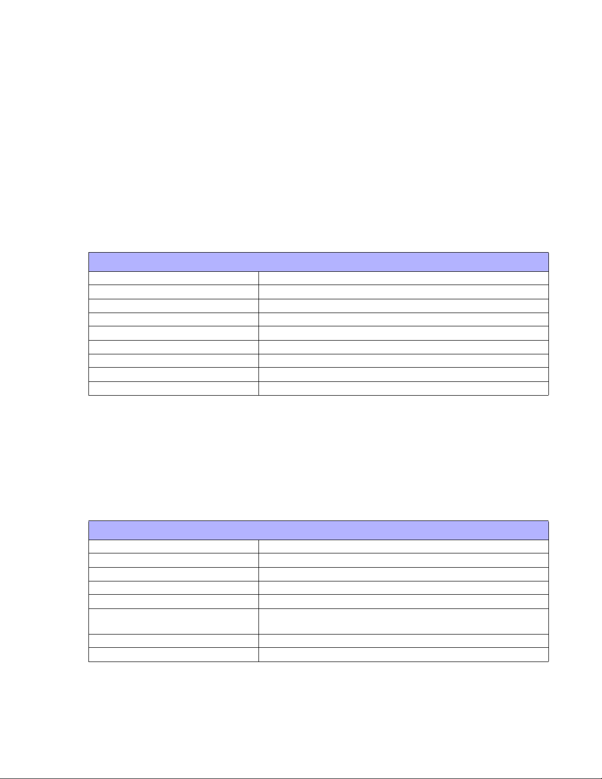
RS232C SPECIFICATIONS
Asynchronous ASCII Half-duplex communication, Bi-Directional Communication
Data Transmission Rate 9600, 19200, 38400, 57600, 115200 bps
Data Length 8 bit (selectable)
Stop Bit 1 bit (fixed)
Parity Bit ODD, EVEN, NONE (selectable)
Codes Used ASC II Character Codes
Control Codes STX (02h), ETX (03h), ACK (06h), NAK (15h)
Connector 8-pin mini - DIN
Cable (8-pin DIN to 9-pin host) Call 704.644.1650
Signal Levels High: +12V, -12V
SATO MB2i Service Manual PN 9001145B Page 3-4
Page 17
Unit 3: Interface Specifications
INFRARED RAYS (IRDA)
Infrared communications is based on technology which is similar to entertainment remote control
devices used in homes today. This technology offers a convient, interoperable, low power, and
reliable way to connect computer and printer without the use of cables. The half-duplex, serial
data interconnection capabilities supports walk up point-to-point use.
The infrared tranmission of print data is transferred from the terminal to the printer in four phases:
(1) Connection, (2) Printer Status Check, (3) Data Transfer, (4) Disconnection.
The limitations of this interface type is that it requires a direct line of sight with a reading span of
30 degrees at a maximum distance of 7-8 inches (20cm). When the peripherals are aligned, they
negociate and transmit/receive data between the two devices.
Default Parameters: DSW1 ON / DSW2-4 OFF.
IRDA SPECIFICATIONS (STANDARD PROTOCOL)
Baud Rate 9600, 19200, 38400, 57600, 115200
Data Bit Length 8
Stop Bit 1
Parity Bit None, Odd, Even
Codes Used ASC-II: 7 bit, Graphics: 8 bit.
Control Codes STX (02h), SYN (16h), ETX (03h), DLE (10h)
Communication Time Time-Out: 5.99 seconds, Retry: over 500 milliseconds.
Receiving Type Single item.
Operations Mode IrSIR v1.2
BHT protocol is the communication procedure used to transmit files between DENSO data
collection devices by adopting the response method using the ACK/NAK codes defined for the
use with these types of devices. Note the IrDA parameters must be set according to PDA/DCS
methods and appropriately configured to direct data transmission to the printer. Refer to the IrDA
command settings in the Programming Reference document for this printer, as well as,
documentation provided by the manufacturer of the data collection device for the proper steps.
The appropriate firmware must be installed to function.
IRDA SPECIFICATIONS (BHT PROTOCOL)
Baud Rate 9600, 19200, 38400, 57600, 115200
Data Bit Length 8
Stop Bit 1
Parity Bit None, Odd, Even
Codes Used ASC-II: 7 bit, Graphics: 8 bit.
Control Codes SOH (01h), STX (02h), ETX (03h), EOT (04h), ENQ (05h), ACK
(06h), DLE (10h), NAK (15h).
Communication Time Time-Out: 5.99 seconds, Retry: over 500 milliseconds.
Receiving Type Single item.
SATO MB2i Service Manual PN 9001145B Page 3-5
Page 18
Unit 3: Interface Secifications
The IrCOMM protocol runs on top of IrDA and supports the emulation of a peer device similar to
what’s connecting it by a serial or parallel cable for applications that access those ports through
the operating system. Since various communication and printing applications utilize cables
differently, cable emulation must account for those differences.
IRDA SPECIFICATIONS (IRCOMM PROTOCOL)
Baud Rate 9600, 19200, 38400, 57600, 115200
Data Bit Length 8
Stop Bit 1
Parity Bit None, Odd, Even
Codes Used ASC-II: 7 bit, Graphics: 8 bit.
Control Codes STX (02h), ETX (03h), ACK (06h), NAK (15h).
Communication Time Time-Out: 5.99 seconds, Retry: over 500 milliseconds.
Receiving Type Single item.
Operations Mode 3-wire cooked
IrOBEX is a communictions protocol that facilitates the exchange of binary objects between
devices and functions similar to HTTP in that a client uses a reliable transport to connect to a
server to request or provide objects. The appropriate firmware must be installed for this to
function.
This is a one-way communications protocol so therefore flow control and printer response are
absent.
IRDA SPECIFICATIONS (IrOBEX PROTOCOL)
Baud Rate 9600, 19200, 38400, 57600, 115200
Data Bit Length 8
Stop Bit 1
Parity Bit None, Odd, Even
Codes Used ASC-II: 7 bit, Graphics: 8 bit.
Control Codes STX (02h), ETX (03h), ACK (06h), NAK (15h).
Communication Time Time-Out: 5.99 seconds, Retry: over 500 milliseconds.
Receiving Type Single item.
SATO MB2i Service Manual PN 9001145B Page 3-6
Page 19

Unit 3: Interface Specifications
BLUETOOTH
Bluetooth is a short-range, wireless technology operating in the unlicensed 2.4GHz band and
offers greater flexibility than IrDA. Its signal is broadcast omni-directional and transmits/receives
up to a distance 30 feet (10 meters).
Typically, the data is directed through a Bluetooth assigned COM port on a PDA which handles
all COM port protocols. Refer to the manufacturer’s documentation PocketPC device setup.
Default Parameters: DSW1,3,4 OFF / DSW2 ON.
SATO MB2i Service Manual PN 9001145B Page 3-7
Page 20

Unit 3: Interface Secifications
ALL INTERFACE TYPES
RECEIVE BUFFER
The data stream is received from the host to the printer one job at a time. This allows the
software program to maintain control of the job print queue so that it can move a high priority job
in front of ones of lesser importance.
The printer receives and prints one job at a time. If a print job exceeds the buffer size,
transmission will be rejected by the printer. Error conditions that occur during the Print Data
transmission will cause the printer to return a NAK.
ACK/NAK PROTOCOL
Bi-Directional ACK/NAK protocol is used for error control. In a normal transmission sequence
when the transmission is received, the printer will return an ACK (06H) signifying that it was
received without a transmission error. After the transmission command structure has been
analyzed, a status byte is returned to the host. This status byte informs the host of the validity of
the command structure.
If the command structure is error free, the printer proceeds with the print operation. When the
print operation is completed, a Printer Status message is returned to the host. If an error was
detected during the initial transmission sequence, a NAK (15H) will be returned signalling to the
host that the received transmission contained errors and must be resent. If the returned Status
byte indicates a command structure error, the error must then be corrected before the print data
is resent to the printer.
A valid transmission to the printer must be bounded by an STX/ETX pair, with the STX (02H)
signifying the start of the Print Data and ending with an ETX (03H) signifying the end.
SATO MB2i Service Manual PN 9001145B Page 3-8
Page 21

Unit 3: Interface Specifications
AD-HOC CONNECTIVITY
To configure the printer for ad-hoc connectivity, an RS232 port and cable is initially required to
use the Wireless Utility. The following two sections provides direction to the necessary tools, then
procede to the next consecutive sections to begin setup.
NOTE: An 8-pin DIN to 9-pin RS232 cable may purchased from SATO.
MB200i WIRELESS LAN CONFIGURATION TOOL (v1.0.0)
The software may be downloaded from:
http://techsubweb.satoamerica.com/public/SAI_site/networking/MB/MB20xi_Cfgtool-setup.zip
Once downloaded, unzip the package and run “setup.exe” to begin installation. Upon completion,
procede as follows: Start/Programs/Sato Tools/LAN Config Tool.
MB200i DRIVER
The driver may be downloaded from: http://techsuweb.satoamerica.com/public/SAI_site/drivers/
v4/SI_PORT.zip. Once downloaded, unzip the package and procede as follows: Control Panel/
Printer and Faxes/Add a Printer. Make the necessary entries on this menu screen to install the
MB200i driver.
.
PRINTER SETUP
Perform the following procedure to configure the printer for ad-hoc interface connectivity.
1. Ensure all of the necessary tools are present.
2. Set all dipswitches to the OFF position to place the printer in the serial mode.
3. Connect the serial cable to the printer and the applicable host computer.
4. Power on the printer.
5. At the host computer, access Control Panel, followed by MB200i folder, and then click on
MB200i Printer Driver.
6. Procede to the SATO MB200i Properties screen (Figure 3-3a/b), then select the Ports tab.
SATO MB2i Service Manual PN 9001145B Page 3-9
Page 22

Unit 3: Interface Secifications
Figure 3-3a/b, SATO MB200i Properties
7. Check the COM1: Serial Port option to assign “SATO MB200i” to that port, then click on
Apply.
8. On the same screen, click on the Configure Port button.
9. When the COM1 Properties screen appears, click on each drop-down menu to change the
settings as follows: 19200 Bits Per Second, 8 Data Bits, no Parity, 1 Stop Bit, no Flow
Control. (Figure 3-4)
Figure 3-4, COM1 Properties
10. Click on the OK button to record the settings.
11. When the Properties screen appears, click on the OK button to record all settings.
12. When the main MB200i driver screen appears, click on its OK button.
SATO MB2i Service Manual PN 9001145B Page 3-10
Page 23
Unit 3: Interface Specifications
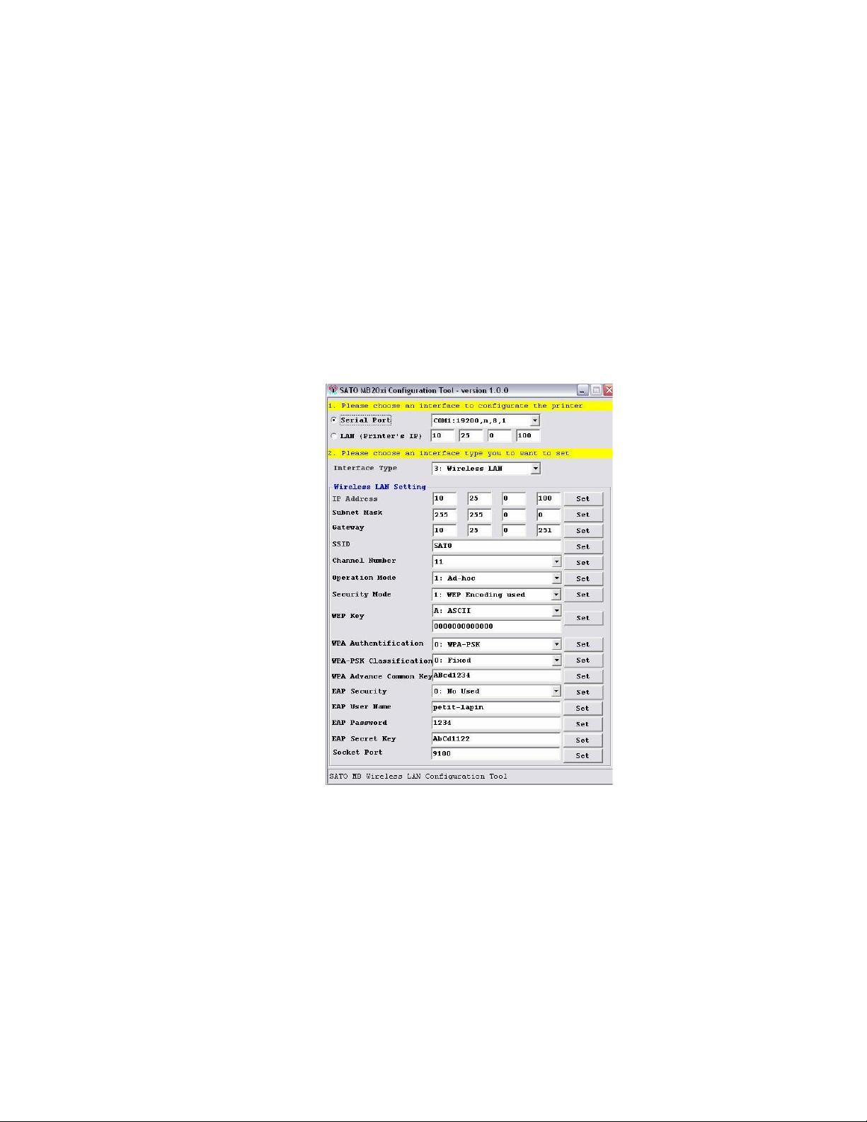
13. Open the SATO MB200i Configuration Tool screen (Figure 3-5) and enter as follows:
• Select the Serial Port option for the interface type. Ensure COM1:19200,n,8,1
displays in the field to the right.
• IP Address: to 150.100.100.1, then press the SET button.
• Subnet Mask: to 255.255.255.0, then press the SET button.
• Gateway: to 0.0.0.0, then press the SET button.
• SSID: to MBPRINT, then press the SET button.
• Channel Number: to 11, then press the SET button.
• Operation Mode: to Ad-Hoc, then press the SET button.
• Security Mode: to Disable WEP, then press the SET button.
• Socket Port: to 9100, then press the SET button.
Figure 3-5, SATO MB200i Configuration Tool
14. Perform the following steps print a test label and verify the settings:
1. Power off the printer and change DSW2 to the ON position.
2 Press and hold the FEED button while powering on the printer. Release when indi-
cators are on.
3 Press the FEED button again to print a test label. Press FEED again to stop.
4 Ensure the contents of the label match those settings of step 13.
15. Ensure the contents of the label match those settings listed in step 13.
16. Repeat steps 2 through 15 if there is a discrepancy between the two.
SATO MB2i Service Manual PN 9001145B Page 3-11
Page 24
Unit 3: Interface Secifications
COMPUTER SETUP
Perform the following procedure to configure the host computer for AD-HOC interface
connectivity.
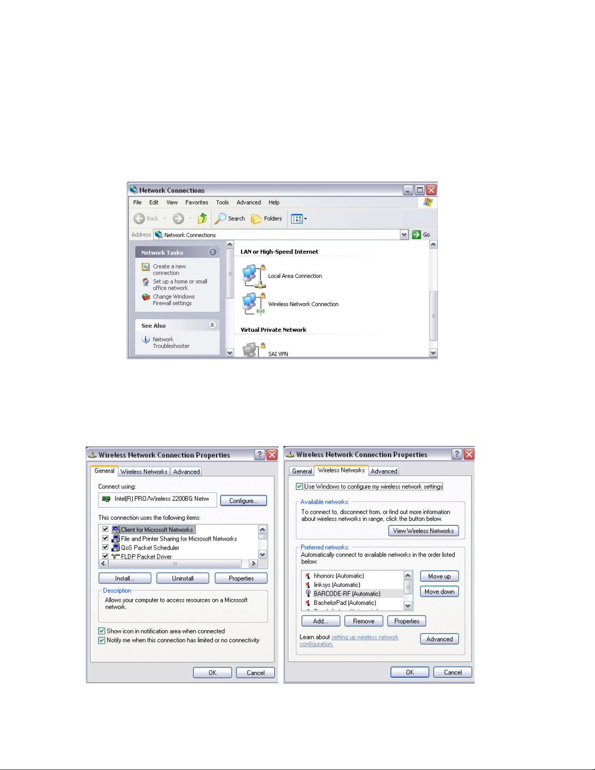
1. At the host computer, access Control Panel and then Network Connections.
2. When the Network Connections screen (Figure 3-6) appears, ensure the icon to the left of
“Wireless Network Connection” does not have a red X over it. Proceed to step 3 if so, exit if
not.
Figure 3-6, Network Connections
3. Click on the icon mentioned in step 2 to proceed to the Wireless Network Connection
Properties screen (Figure 3-7a/b).
4. Click on the Wireless Networks tab to view that menu, then on the Advanced button.
Figure 3-7a/b, Wireless Network Connection Properties
SATO MB2i Service Manual PN 9001145B Page 3-12
Page 25
Unit 3: Interface Specifications
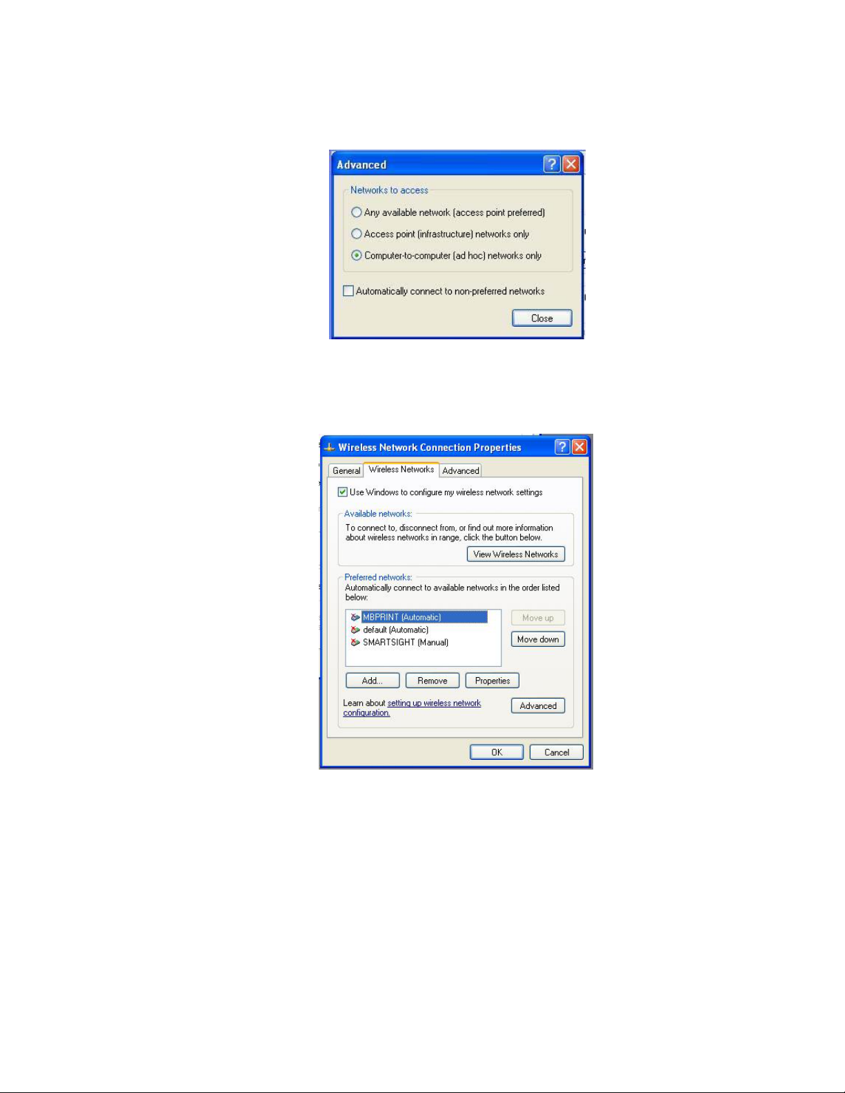
5. When the Advanced screen (Figure 3-8) appears, select the Computer-To-Computer
option, followed by the Close button.
Figure 3-8, Advanced
6. When the Wireless Network Connection Properties Figure 3-9) screen reappears, click on
the Add button to add a network matching that of the printer.
Figure 3-9, Wireless Network Connection Properties
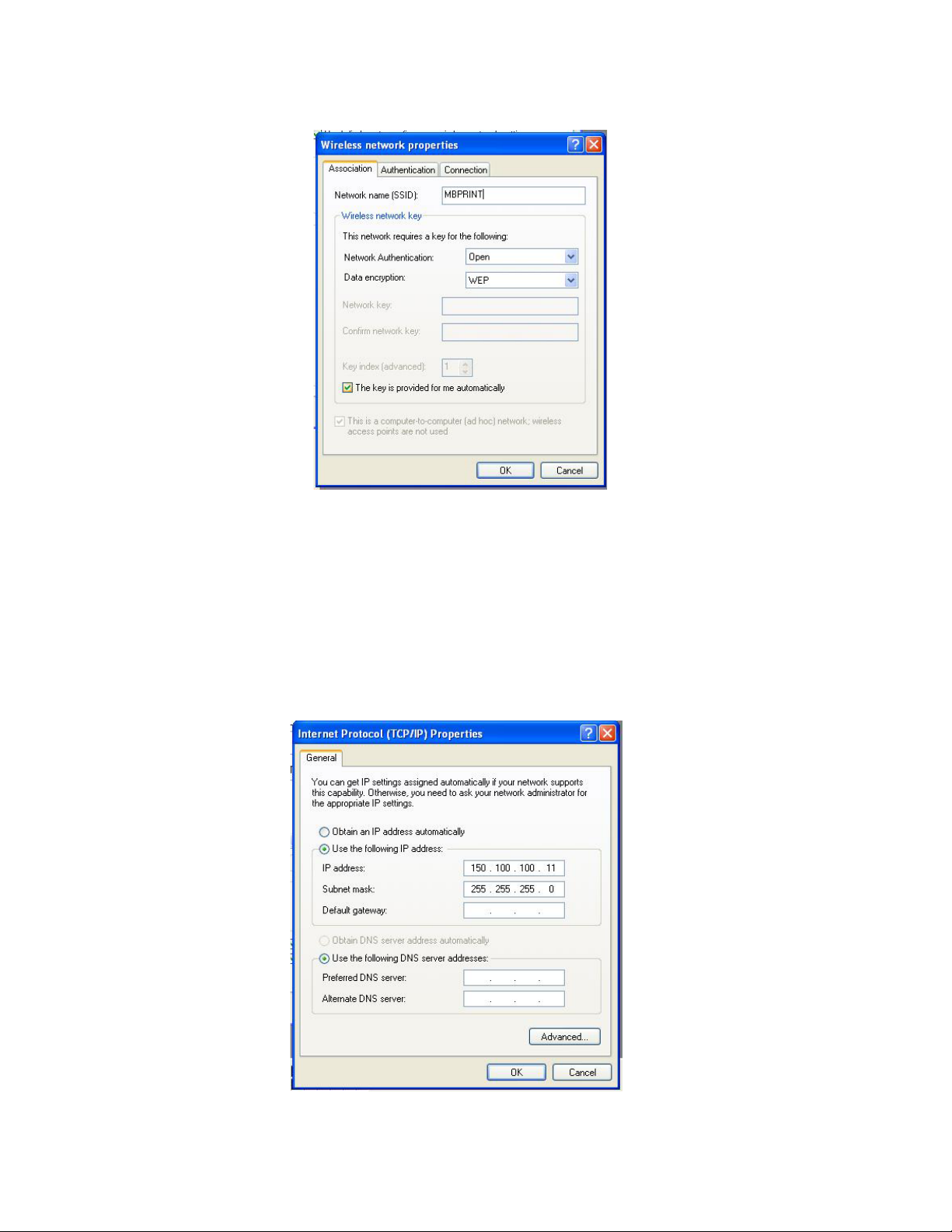
7. When the Wireless Network Properties (Figure 3-10) screen appears, input MBPRINT in
the Network Name (SSID) field.
8. Alter the following fields as necessary:
• Network Authentication: Open.
• Data Encryption: Disabled.
9. Press the OK button to enter the selections.
SATO MB2i Service Manual PN 9001145B Page 3-13
Page 26
Unit 3: Interface Secifications
Figure 3-10, Wireless Network Properties
10. When the Wireless Network Connection Properties screen (Figure 3-9) appears, ensure
that MBPRINT is displayed as the preferred network. If not, repeat steps 4 through 10.
11. Click on the General tab to view that menu.
12. Scroll the “This connection uses” field to view the Internet Protocol (TCP/IP) option and
select it.
13. When the Internet Protocol (TCP/IP) Properties screen (Figure 3-11) appears, select the
“Use the following IP address” option to activate those items.
Figure 3-11, Internet Protocol (TCP/IP) Properties
SATO MB2i Service Manual PN 9001145B Page 3-14
Page 27

Unit 3: Interface Specifications
14. Alter the following fields as necessary:
• IP Address: Change to 150.100.100.11 .
• Subnet Mask: 255.255.255.0 (should always be the same)
15. Click on the OK button to exit the Internet Protocol (TCP/IP) screen.
16. When the Wireless Network Connection Properties screen (Figure 3-9) reappears, click on
the OK button to exit.
17. To test the ad-hoc wireless connection, perform the following procedure:
1. Access Control Panel/MB200i Print Driver/Printer and Faxes, then click on
MB200i Printer Driver.
2. When SATO MB200i Properties screen (Figure 3-12a) appears, select Ports tab.
3. When the Ports menu (Figure 3-12b) appears, click on the Add Port button.
Figure 3-12a/b, Ports
4. When the Printer Ports screen (Figure 3-13) appears, select the Standard TCP/IP
Port option followed by the New Port button.
Figure 3-13, Printer Ports
SATO MB2i Service Manual PN 9001145B Page 3-15
Page 28

Unit 3: Interface Secifications
5. When the TCP/IP Wizard welcome screen (Figure 3-14) appears, press the Next
button.
Figure 3-14, TCP/IP Wizard Welcome Screen
6. Input the same IP Address as the printer in the field adjacent to the Printer Name/
IP Address prompt. Press the Next button. (Figure 3-15)
Figure 3-15, TCP/IP Wizard Entry Screen
SATO MB2i Service Manual PN 9001145B Page 3-16
Page 29

Unit 3: Interface Specifications
7. Press the Finish button when the TCP/IP Wizard exit screen (FIgure 3-16)
appears.
Figure 3-16, TCP/IP Wizard Exit Screen
18. At the SATO MB200i Properties screen, ensure the following is displayed:
• Port: IP Address of the printer.
• Description: Standard TCP/IP
• Printer: MB200i
19. At the SATO MB200i Properties screen (Figure 3-17), press the Print Test Page button to
print a test label.
20. Press the Apply button, followed by the OK button, to exit the SATO MB200i Properties
screen.
SATO MB2i Service Manual PN 9001145B Page 3-17
Page 30

Unit 3: Interface Secifications
Figure 3-17, SATO MB200i Properties
SATO MB2i Service Manual PN 9001145B Page 3-18
Page 31

LCD DISPLAY
• Display Fields
•LCD Screens
• Maintenance Mode
SATO MB2i Service Manual PN 9001145B Page 4-1
Page 32

Unit 4: LCD Display
DISPLAY FIELDS
The LCD Display is an intergrated purchase option only and applicable only for the Wireless LAN
and interface. Due to its limited application, this is the only unit within this manual that covers the
LCD display. All of its features, functions, and menus are identified and defined here.
1
2
3
Figure 4-1, LCD Display
The LCD has three field areas of display; two graphical and one for text. They are as follows:
1. Graphical Battery charge status.
2. Graphical Electrical field strength for the Wireless LAN.
3. Text Two text lines showing the printer’s status.
BATTERY LEVEL (1)
The battery charge of the printer’s power pack is displayed in four graduations as identified in the
table below. The battery charge will always be displayed in field 1 as shown in Figure 4-1 above.
ICON DESCRIPTION
Displays a full charge of 8.0 volts or more.
Displays the detected voltage is between 7.8 and 7.9.
Displays the detected voltage is between 7.6 and 7.7. The printer
will go into the Sleep Mode and the LED will blink every 4 seconds.
Displays the detected voltage level is less than 7.5. The printer will
automatically power off 30 seconds after displaying this icon.
SATO MB2i Service Manual PN 9001145B Page 4-2
Page 33

Unit 4: LCD Display
WIRELESS FIELD STRENGTH (2)
When the Wireless LAN has been set, the received electric field strength will be displayed using
one of the following four icons. The field strength will always be displayed in field 2 as shown in
Figure 4-1 above.
ICON DESCRIPTION
Maximum Strength.
Medium Strength.
Minimum Strength.
No Strength.
OPERATIONAL STATUS (3)
The printer’s operational status is displayed in text form and will always be located in field 3 as
shown in Figure 4-1 above. The following tables identify and define each of the LCD screens
within the operational and maintenance menus.
SATO MB2i Service Manual PN 9001145B Page 4-3
Page 34

Unit 4: LCD Display
LCD SCREENS
STARTUP
STATUS LCD DETAIL
Formatting Displays the SATO logo and the phase “Farm
Version” (Farm Ware Version) for a second upon
SATO
DCS & Labeling Wordwide
[Firm Version]
NORMAL MODE
STATUS LCD DETAIL
Online Displays the operational condition in the first line
startup.
and the remaining print quantity in the second.
ONLINE
QTY: 0000
Offline Displays the operational condition in the first line
and the remaining print quantity in the second.
OFFLINE
QTY: 0000
Sleep Mode Not Available. Nothing is displayed while in the sleep mode.
TEST PRINT MODE
STATUS LCD DETAIL
Pausing Test Printing Displays the current mode to be performed.
Electric field strength icon for Wireless LAN is not
TEST PRINT
PRESS FEED KEY
Test Printing Displays the current mode and that the function
TEST PRINT
PRINTING
displayed.
has been completed.
Electric field strength icon for Wireless LAN is not
displayed.
SATO MB2i Service Manual PN 9001145B Page 4-4
Page 35

Unit 4: LCD Display
DEFAULT SETTING MODE
STATUS LCD DETAIL
Default Setting Displays the current mode to be performed.
Electric field strength icon for Wireless LAN is not
DEFAULT
SETTING
displayed.
Default Setting
Completed
COMPLETE
Displays the current mode and that the function
has been completed.
Electric field strength icon for Wireless LAN is not
displayed.
FACTORY CLEAR MODE
STATUS LCD DETAIL
Factory Clear Displays the current mode to be performed.
Electric field strength icon for Wireless LAN is not
FACTORY CLEAR
Factory Clear
Completed
FACTORY CLEAR
PRESS FEED KEY
displayed.
Displays the current mode and that the function
has been completed.
Electric field strength icon for Wireless LAN is not
displayed.
HEX DUMP MODE
STATUS LCD DETAIL
Hex Dump Displays the current mode to be performed.
Electric field strength icon is only displayed if
HEX DUMP MODE
SATO MB2i Service Manual PN 9001145B Page 4-5
Wireless LAN is set as the interface type.
Page 36

Unit 4: LCD Display
PRINTER ERRORS
STATUS LCD DETAIL
Low Battery Displays location of error. The battery icon will
display a low charge condition and blink.
BATTERY
ERROR
Module Error Displays location of error. This will indicate an
MODULE
ERROR
Head Error Displays location of error. This will indicate an
HEAD
ERROR
The electric field strength icon will only be
displayed if Wireless LAN is set as the interface
type.
error was detected in the Wireless LAN or
Bluetooth interface as applicable.
The electric field strength icon will only be
displayed if Wireless LAN is set as the interface
type.
error was detected with the print head.
The electric field strength icon will only be
displayed if Wireless LAN is set as the interface
type.
Cover Open Displays location of error. This will indicate the top
housing cover is not latched.
COVER
OPEN
The electric field strength icon will only be
displayed if Wireless LAN is set as the interface
type.
Paper End Displays location of error. This will indicate that
the paper supply is exhausted. Reload.
PAPER
END
The electric field strength icon will only be
displayed if Wireless LAN is set as the interface
type.
Sensor Error Displays location of error. This will indicate an
error was detected with a sensor. Troubleshoot.
SENSOR
ERROR
The electric field strength icon will only be
displayed if Wireless LAN is set as the interface
type.
Buffer Near Full Displays location of error. This will indicate the
receive buffer is at capacity.
NEAR
FULL
The electric field strength icon will only be
displayed if Wireless LAN is set as the interface
type.
Head Protect Displays location of error. This will indicate the
status of the head protect feature.
HEAD
PROTECT
The electric field strength icon will only be
displayed if Wireless LAN is set as the interface
type.
SATO MB2i Service Manual PN 9001145B Page 4-6
Page 37

Unit 4: LCD Display
MAINTENANCE MODE
The Maintenance Mode allows for the Wireless LAN to be configured and/or the LCD Display.
While in this mode, the PRINT key is used for option selection and the FEED key serves to enter
the selection.
MAINTENANCE MODE
STATUS LCD DETAIL
Initial Screen Allows the selection of whether to setup the
Wireless LAN interface or to modiy the LCD
=> SET UP
DISPLAY
LCD SETUP
STATUS LCD DETAIL
display.
Setup menu Allows the selection of whether to modify the LCD
display or to exit. If EXIT is chosen, the display will
return to the initial screen of the Maintenance
=> ADJUST LCD
EXIT
Mode.
Electric field strength icon for Wireless LAN is not
displayed.
Contrast Adjustment Allows the adjustment of the LCD contrast.
Electric field strength icon for Wireless LAN is not
CONTRAST
xx
displayed.
Backlight Setting Allows the adjustment of the LCD backlighting.
Electric field strength icon for Wireless LAN is not
BACK LIGHT
ON
displayed.
SATO MB2i Service Manual PN 9001145B Page 4-7
Page 38

Unit 4: LCD Display
WIRELESS LAN
STATUS LCD DETAIL
Setup Menu Allows the selection of whether to setup the
wireless LAN or to exit. If EXIT is chosen, the
=> WLAN INFO
EXIT
Wireless LAN Mode Socket Port Number is displayed.
WLAN MODE
[information]
Channel Channel information is displayed.
WLAN CHANNEL
[information]
display will return to the initial screen of the
Maintenance Mode.
IP Address Current IP Address is displayed.
IP ADDRESS
XXX.XXX.XXX.XXX
Subnet Mask Current subnet mask is displayed.
SUBNET MASK
XXX.XXX.XXX.XXX
Gateway Address Gateway address is displayed.
DEFAULT GATEWAY
XXX.XXX.XXX.XXX
Socket Port Number Socket Port Number is displayed.
SOCKET PORT
XXXX
SATO MB2i Service Manual PN 9001145B Page 4-8
Page 39

PRINTER
CONFIGURATION
• Printer Configuration
• Configuration Modes
SATO MB2i Service Manual PN 9001145B Page 5-1
Page 40

Unit 5: Printer Configuration
PRINTER CONFIGURATION
The keys of the operator panel and dip switches are used either singularly or in conjuction to
perform configuration activities. The dip switch complex is accessible from the right housing
cover.
Refer to the Control Features chapter of the Introduction Unit for identification of specific
interface features.
FACTORY DEFAULTS
DSW1 DSW2 DSW3 DSW4
OFF OFF OFF OFF
RS232C QUICK REFERENCE TABLE
DESCRIPTION DIP SWITCHES HEAD PRINT KEY FEED KEY
Standard Start-Up OFF OFF OFF OFF Closed OFF OFF
User Test Print Closed OFF ON
Default Reset Opened ON OFF
Hex Dump OFF OFF ON ON Closed OFF OFF
Font Download OFF OFF OFF ON Closed OFF OFF
Dispense Auto Print Opened ON OFF
Dispense Manual Print Opened OFF OFF
Program Download OFF OFF ON OFF Closed OFF OFF
Factory Clear (w/o counter) Opened ON ON
Head Check OFF ON OFF ON Opened ON OFF
Cancel Head Check Opened OFF ON
Factory Clear (w’counter) OFF ON ON OFF Opened ON ON
IRDA QUICK REFERENCE TABLE
DESCRIPTION DIP SWITCHES HEAD PRINT KEY FEED KEY
Standard Start-Up ON OFF OFF OFF Closed OFF OFF
User Test Print Closed OFF ON
Hex Dump ON OFF ON ON Closed OFF
Head Check ON OFF OFF ON Opened ON OFF
Cancel Head Check Opened OFF ON
Factory Clear (w/counter) ON OFF ON OFF Opened ON ON
Online Command (MB200) ON ON ON ON Opened ON OFF
Online Command (SBPL) Opened OFF ON
SATO MB2i Service Manual PN 9001145B Page 5-2
Page 41

Unit 5: Printer Configuration
BLUETOOTH QUICK REFERENCE TABLE
DESCRIPTION DIP SWITCHES HEAD PRINT KEY FEED KEY
Normal Mode OFF ON OFF OFF Closed OFF OFF
User Test Print Mode Opened OFF ON
Maintenance Mode Opened ON OFF
Hex Dump OFF ON ON ON Closed OFF OFF
Enable CRC (Digit Check) OFF OFF OFF ON Closed OFF OFF
Disable CRC (Digit Check) Opened ON OFF
Set Head Check OFF ON OFF ON Opened ON OFF
Cancel Head Check Opened OFF ON
Factory Clear (w/head clear) OFF ON ON OFF Opened ON ON
WIRELESS LAN QUICK REFERENCE TABLE
DESCRIPTION DIP SWITCHES HEAD PRINT KEY FEED KEY
Normal Mode OFF ON OFF OFF Closed OFF OFF
User Test Print Mode Opened OFF ON
Maintenance Mode Opened ON OFF
Hex Dump OFF ON ON ON Closed OFF OFF
Enable CRC (Digit Check) OFF OFF OFF ON Closed OFF OFF
Disable CRC (Digit Check) Opened ON OFF
Set Head Check OFF ON OFF ON Opened ON OFF
Cancel Head Check Opened OFF ON
Factory Clear (w/head clear) OFF ON ON OFF Opened ON ON
SATO MB2i Service Manual PN 9001145B Page 5-3
Page 42

Unit 5: Printer Configuration
CONFIGURATION MODES
This chapter provides an overview of the various configuration modes of the operation menu. All
of the following configuration activities are performed via the use of the operator panel located on
the printer front. However, many settings may also be controlled via software commands. In the
case of conflict between the software and control panel settings, the printer will always use the last
entered valid setting.
NORMAL MODE
When in the Normal Mode the printer is online and ready for print activity. If print activity,
downloading, or other interaction does not occur, the printer will go into the Sleep Mode and from
there, into the Offline Mode.
Refer to Figure 1-1 in the Introduction unit of this manual for dipswitch location.
RS232C: (DSW = 1: OFF, 2: OFF, 3: OFF, 4: OFF) + POWER
Wireless LAN: (DSW = 1: OFF, 2: ON, 3: OFF, 4: OFF) + POWER
Bluetooth: (DSW = 1: OFF, 2: ON, 3: OFF, 4: OFF) + POWER
Infrared: (DSW = 1: ON, 2: OFF, 3: OFF, 4: OFF) + POWER
Flashes orange,
goes onli ne,
flashes green
PRINT
terminates and pr int er goes
LED
offline
FEEDFEED
Label is fed
Figure 5-1, Normal Mode
SATO MB2i Service Manual PN 9001145B Page 5-4
Page 43

Unit 5: Printer Configuration
LABEL SENSOR SELECTION
This function allows for the determination of the sensor to be used to control label positioning
relative to the media type that will be used. The two options are; eye-mark and gap. This
selection can only be made through host interface using a RS232C cable.
POWER = OFF
Connect the printer to the
host with RS232C cable.
Send printer operation
registration command
from the host and select
the desired label type.
Print a label.
Power off and
disconnect cable.
Printer shuts down.
Adjustment
successful?
Yes / No
Figure 5-2, Label Sensor Selection
SATO MB2i Service Manual PN 9001145B Page 5-5
Page 44

Unit 5: Printer Configuration
DISPENSE MODE
This feature allows for the determination of the method of dispense.
AUTO Prints a single label after receiving data, waits for
the label to be retrieved, then automatically prints
the next label.
MANUAL Prints a single label after receiving data and then
goes offline. Prints a single label each time the
PRINT key is pressed until the specified number of
labels has been printed. A new job will have to be
dowloaded to print more.
Refer to Figure 1-1 of the Introduction unit in this manual for dipswitch location.
Auto Dispense: (DSW = 1: OFF, 2: OFF, 3: OFF, 4: ON) + PRINT + POWER
Manual Dispense: (DSW = 1: OFF, 2: OFF, 3: OFF, 4: ON) + FEED + POWER
Choose Applicabl e Option
Blinks green whil e setting.
Flashes gr een when complete.
Press POWER and
return dip switches to
their previous positions.
Printer shuts down and exits
Dispense Mode.
Figure 5-3, Dispense Mode
SATO MB2i Service Manual PN 9001145B Page 5-6
Page 45

Unit 5: Printer Configuration
DOWNLOAD MODE
This download feature allows the operator to download print jobs to the printer. The data is
received through an RS232C interface in binary form using XMODEM protocol for file transfer.
Refer to Figure 1-1 of the Introduction unit in this manual for dipswitch location.
DSW = 1: OFF, 2: OFF, 3: ON, 4: OFF + POWER
Flashes
orange and enters the
Program Download Mode.
Format storage area if
never done.
Blinks green while waiti ng
for data.
Confirm the printer is
standing by for data
before sending.
Send data.
Ensure the printer is
waiting for data to be
sent before powering off.
Press POWER.
Printer
shuts down. Must be restarted
to use the downloaded
data.
Flashes green whil e receiving
changes from red to orange to
green when writi ng data to
data.
LED
Flash ROM.
Flashes green when
complete.
Figure 5-4, Program Download Mode
In XMODEM protocol, data is transferred block by block. Each starts with SOH(01h) and consists
of 132 bytessuch as block number (BLK) of 1 byte, complement of block number (_BLK), 128
bytes main data, and check sum (SUM) of 1 byte.
SATO MB2i Service Manual PN 9001145B Page 5-7
Page 46

Unit 5: Printer Configuration
The block number starts from 1, and when counting to 255, the number goes back to 0 again. If
the block number is [01h], complement of block number becomes [FEh]. In the main data, the
section of data by 128 bytes is stored. SUM is the check sum computed from 128 bytes of main
data.
NOTE: The above method is XMODEM (check sum) option. Select
check sum option in the XMODEM settings on the host side.
When downloading data, the format is such that the first 16 bytes are used as header information
and the rest is considerred as data. The header information is divided thusly: code (4 bytes), start
address (4 bytes), file size (4 bytes), and reserved area (4 bytes). The remaining optional data is
to be stored in Flash ROM.
The basic sequence of XMODEM is to transfer data blocks by individually checking response
blocks. NAK (15h) transmission by the receiving end initiates the sequence, and the sending end
sends the first data block after receiving NAK. The receiving end receives and checks this data
block, and then returns ACK (06h) in case of no error or NAK (15h) in case of an error. The
sending end sends the next block when receiving ACK, and resends the same block when
receiving NAK. This process repeats to the first block. EOT (04h) is sent from the sending end to
receiving end at the end of all data transmission. After receiving EOT (04h), the receiving end
returns ACK to terminate the sequence.
SATO MB2i Service Manual PN 9001145B Page 5-8
Page 47

Unit 5: Printer Configuration
FONT DOWNLOAD MODE
A flash ROM is used to internally store and delete font data and custom designed data. The
storage capacity for custom designed characters is a maximum of 95 for each of type of 16 x 16,
22 x 22, 24 x 24 dots.
There are four transmission protocols for font download: (1) Download Font Storage, (2)
Download Font Selection, (3) Download Font Information Aquisition, (4) Storage CustomDesigned Character. The return status from the printer is set between STX (02h) and ETX (03h),
and transferred in 3 bytes.
Wiring on the computer side may require a CTS (pin 5) and RTS (pin 4) cable connection.
Confirm the host settings before downloading.
Figure 5-5 provides the specific sequence of events required by the operator, the printer, and the
printers software for font download mode to be activated.
Refer to Figure 1-1 of the Introduction unit in this manual for dipswitch location.
A detailed description of how to download data is in the Programming Reference.
DSW = 1: OFF, 2: OFF, 3: OFF, 4: ON + POWER
Flashes
orange and enters the
Font Download Mode.
Format storage area if
never done.
Blinks green whil e waiting
for data.
Confirm the printer is
standing by for data
before sending.
Send data.
Flashes green while receiving
data.
LED
changes from red to orange to
green when writing data to
Flash ROM.
Ensure the printer is
waiting for data to be
sent before powering off.
Press POWER.
Printer shuts down.
Figure 5-5, Font Download Mode
SATO MB2i Service Manual PN 9001145B Page 5-9
Page 48

Unit 5: Printer Configuration
DOWNLOAD FONT REGISTRATION
STATUS DESCRIPTION ACSII HEX TRANSFER
Not Already Stored A 41 Printer to Host
Already Stored B 42 Printer to Host
Storage Area NG N 4E Printer to Host
Store Font 0 30 Host to Printer
Do Not Store Font 1 31 Host to Printer
Ready For Storage Status O 4F Printer to Host
Font Storage Completed Normally E 45 Printer to Host
Font Storage Cancelled S 53 Printer to Host
Font Storage Completed Abnormally Z 5A Printer to Host
DOWNLOAD FONT DELETION
STATUS DESCRIPTION ACSII HEX TRANSFER
Not Already Stored A 41 Printer to Host
Already Stored B 42 Printer to Host
Delete Font 0 30 Host to Printer
Do Not Delete Font 1 31 Host to Printer
Font Deletion Completed Normally E 45 Printer to Host
Font Deletion Cancelled S 53 Printer to Host
Font Storage Completed Abnormally Z 5A Printer to Host
DOWNLOAD FONT INFORMATION AQUISTION
STATUS DESCRIPTION ACSII HEX TRANSFER
Not Already Stored A 41 Printer to Host
Already Stored B 42 Printer to Host
Font Information Transferred OK 0 30 Host to Printer
Number of Transferred Data 000000-
999999
Font Information Font Info Data + Font
6 bytes w/
Data Info
Printer to Host
30-39
Printer to Host
STORAGE OF CUSTOM DESIGNED CHARACTER
STATUS DESCRIPTION ACSII HEX TRANSFER
Storage Ready Status O 4F Printer to Host
Storage Completed Normally E 45 Printer to Host
Storage Completed Abnormally Z 5A Host to Printer
SATO MB2i Service Manual PN 9001145B Page 5-10
Page 49

Unit 5: Printer Configuration
ONLINE COMMAND MODE
This function allows the selection of receiving command by using either standard SATO Barcode
Printer Language (SBPL) or first generation MB200 compatible commands. The MB200
compatible command option should only be chosen if first generation MB200’s will be used along
with the newer generation. This will provide a common command language that will
communicate to both.
Refer to Figure 1-1 of the Introduction unit in this manual for dipswitch location.
MB200 Compatibility Mode: (DSW = 1: ON, 2: ON, 3: ON, 4: ON) + Cover Open + PRINT + POWER
SBPL Mode: (DSW = 1: ON, 2: ON, 3: ON, 4: ON) + Cover Open + FEED + POWER
Choose Applicable Option
Blinks green when setti ng
Online Command.
Flashes green when setting
completed.
Confirm setting is
complete.
Press POWER.
Printer shuts down.
Figure 5-6, Online Command Mode
SATO MB2i Service Manual PN 9001145B Page 5-11
Page 50

Unit 5: Printer Configuration
CRC (CYCLIC REDUNDANCY CHECK) MODE
Allows the operator to enable or disable the Cyclic Redundancy Check (CRC) for each received
print data when using wireless LAN or Bluetooth interface.
Refer to Figure 1-1 of the Introduction unit in this manual for dipswitch location.
Enable CRC Check: (DSW = 1: OFF, 2: ON, 3: ON, 4: ON) + Cover Open + PRINT + POWER
Disable CRC Check: (DSW = 1: OFF, 2: ON, 3: ON, 4: ON) + Cover Open + FEED + POWER
Choose Applicable Option
Flashes green when savi ng
the Head Check setti ng.
Flashes green when set ting
completed.
Confirm setting is
complete.
Press POWER.
Printer shuts down.
Figure 5-7, CRC Check Mode
SATO MB2i Service Manual PN 9001145B Page 5-12
Page 51

Unit 5: Printer Configuration
SLEEP & AUTO-OFF MODE
This mode is a non-interactive mode that is provided to explain the timed sequence of events that
relate to the printer going into sleep mode and then futher into offline mode.
Printer in Normal Mode
No operator interaction or printer
operation for 5 seconds.
Sleep Mode. LED blinks green
Send data or press key.
signal occurs and goes into
Error
every 4 seconds.
No operator interaction or printer
operation for 5 minutes.
Error
signal occurs and printer
automatically switches itself off.
LED terminates.
Figure 5-8, Sleep & Auto-Off Mode
SATO MB2i Service Manual PN 9001145B Page 5-13
Page 52

Unit 5: Printer Configuration
SATO MB2i Service Manual PN 9001145B Page 5-14
Page 53

TROUBLESHOOTING
• Error Signals
• Troubleshooting Table
• Interface Troubleshooting
• Test Print Troubleshooting
SATO MB2i Service Manual PN 9001145B Page 6-1
Page 54

Unit 6: Troubleshooting
ERROR SIGNALS
LED MODE DESCRIPTION
Red
illuminated
Red
flashing
2.0 seconds
Red
illuminated
Alternating
Green/Red
2.0 seconds
Red flashing
0.5 seconds
Green
flashing
0.5 seconds
All modes
Online
After power On
Online
Online
Online
(during printing &
data receiving)
Cause: Low battery charge.
Remedy: Recharge/ replace battery.
Cause(s): Bluetooth or Wireless LAN malfunction.
Remedy: Replace the interface module.
Cause(s): 1. Progrom error.
2. Flash ROM error.
Remedy: 1. Download program again.
2. Replace Flash ROM.
Cause(s): Defective print head.
Remedy: Replace print head.
Cause(s): 1. Cover is not latched or sensor is defective.
2. Paper End sensor incorrectly set.
3. Incorrect media sensor selection or adjustment.
Remedy: 1. Latch cover or replace print head.
2. Properly set Paper End sensor.
3. Select correct sensor & adjust. Replace bord as required.
Cause(s): Size of received data exceeds size of receiving buffer.
Remedy: Temporarily stop sending data until space is free.
Green
flashing
4.0 seconds
Alternating
Green/Red
1.0 seconds
All Modes
All Modes
Cause(s): Is in Sleep Mode. Not an error.
Remedy: Will cease when data is received, a key pressed, or cover opened.
Cause(s): Print head is hotter than 70 degrees celsius.
Remedy: Cease printing until the print head has cooled to 50 degrees celsuis
or less.
SATO MB2i Service Manual PN 9001145B Page 6-2
Page 55

Unit 6: Troubleshooting
TROUBLESHOOTING TABLE
IMAGE VOIDS
Damaged print head or electronics. Replace as required.
Damaged or worn platen roller. Replace platen roller.
Vertical line in printed image. Dirty or defective print head.
LIGHT PRINT IMAGES
Low print head energy/darkness. Adjust darkness control.
Foreign material on print head. Clean print head and platen roller.
Excessive print speed. Reduce print speed setting.
UNEVEN PRINT DARKNESS
Worn platen roller. Replace platen roller as required.
Dirty print head. Clean as necessary.
SMEARED PRINT IMAGES
Poor label quality. Use higher quality label stock.
Debris on print head & platen roller. Clean print head and platen roller.
NO LABEL MOVEMENT
Incorrect label pitch sensor selected. Select the correct label sensor type.
No voltage output. Test power supply or battery and replace as required.
Drive motor not operating. Ensure wiring harness connection.
Defective main board. Contact SATO Service or Technical Support.
NO PRINTED IMAGE
No voltage output. Test power supply or battery and replace as necessary.
Damaged print head. Replace as required.
Interface problems. Check interface connection.
Data input error. Ensure correct data stream.
MEANDERING MEDIA
Incorrectly loaded media. Ensure correct loading.
Improperly adjusted media guides. Adjust as required.
PRINTER CREATES A BLANK LABEL
Data input error. Ensure correct data stream.
Improper top of form selected. Ensure correct top of form is in use (Gap, Blackban).
Defective print head. Replace print head as required.
SATO MB2i Service Manual PN 9001145B Page 6-3
Page 56

Unit 6: Troubleshooting
INTERFACE TROUBLESHOOTING
RS232 SERIAL INTERFACE
CHK TROUBLESHOOTING STEP
Ensure the correct interface module is correctly installed. Run self-test to verify.
Ensure the serial cable (Null Modem) meets specifications and is correctly connected at each end.
Ensure the serial cable is not defective.
Ensure the communication parameters for the baud rate, parity, data bits and stop bits are consistent with those being sent from the host computer.
Ensure the printer is receiving information from the computer using the Receive Buffer Hex Dump
mode. Refer to that procedure within this manual for instructions. The command stream should be
continuous and possess 0Dhex and/or 0Ahex (carriage return and line feed) characters throughout. However, there should not be either locate between the start (<ESC>A and the stop
(<ESC>Z) commands.
Replace the interface board with another to isolate the problem.
Replace the interface baord permanently if determined to be the problem.
WIRELESS ETHERNET INTERFACE
CHK TROUBLESHOOTING STEP
Ensure the printer is the Wireless LAN model that comes equipped with an LCD screen.
Ensure the printer’s dipswitches are set to OFF, ON, OFF, OFF.
Ensure the configuration setting for the device is correct. Ensure the network is correctly configured for the MB200i/MB201i printer. This may be verified by performing a test print to view the current settings. Ensure the IP address, subnet mask, gateway and security settings are sychonized
to match the system network’s settings (your network administrator can verify). Alternately, check
the settings via the printer’s LCD by invoking its Maintenance Mode.
Ensure the access point communication link is correct. Perform a communications test to determine if the access point is responding. Start a command prompt window on a Windows PC
through a wired network and ping the wireless access point’s IP adress - the wireless access point
should respond to the ping. If not, there is either a break in the communication link or the access
point is malfunctioning or improperly configured.
Ensure the Wireless communication link is correct. Then execute the Command prompt on a PC
and ping the printer - the device sould respond to the ping. If not, there is either a break in the
communications link or the printer was not properly configured. Check the printer’s settings again.
Attempt to ping the printer again from a wired/wireless client. If the ping still fails, the unit is
probably malfunctioning and should be replaced. Contact SATO technical staff for assistance.
SATO MB2i Service Manual PN 9001145B Page 6-4
Page 57

Unit 6: Troubleshooting
TEST PRINT TROUBLESHOOTING
Chapter provides instruction on special printing to identify and resolve specific print problems.
HEX DUMP Allows the operator to determine if there were
problems in the downloading of data.
TEST LABEL Allows the operator to identify specific problems
regarding mechanical performance and setup.
HEX DUMP MODE
The contents of the print buffer can be examined using the Hex Dump Mode. In the left column,
each line of data received is numbered. The center column provides the data in hexadecimal
format. And in the right column, same data is provided in the ASC ll format. Follow the flow chart
provided below to perform this activity.
Refer to Figure 1-1 of the Introduction unit in this manual for dipswitch location.
RS232C: (DSW = 1: OFF, 2: OFF, 3: ON, 4: ON) + POWER
Wireless LAN: (DSW = 1: OFF, 2: ON, 3: ON, 4: ON) + POWER
Bluetoot h: (DSW = 1: OFF, 2: ON, 3: ON, 4: ON) + POWER
Infrared: (DSW = 1: ON, 2: OFF, 3: ON, 4: ON) + POWER
Choose Applicable Option
Flashes
orange and enters the
Hex Dump Mode.
Receives data and begins
print ing.
Return dip switches to
their previous positions
and press POWER.
Printer shuts down and exists
Hex Dump Mode.
Figure 6-1, Hex Dump Mode
SATO MB2i Service Manual PN 9001145B Page 6-5
Page 58

Unit 6: Troubleshooting
TEST LABEL PRINTING
The test label is designed to assist in the identification of print problems. Follow the flow chart
provided below to perform this activity.
Refer to Figure 1-1 of the Introduction unit in this manual for dipswitch location.
RS232C: (DSW = 1: OFF, 2: OFF, 3: OFF, 4: OFF) + FEED + POWER
Wireless LAN: (DSW = 1: OFF, 2: ON, 3: OFF, 4: OFF) + FEED + POWER
Bluetooth: (DSW = 1: OFF, 2: ON, 3: OFF, 4: OFF) + FEED + POWER
Infrared: (DSW = 1: ON, 2: OFF, 3: OFF, 4: OFF) + FEED + POWER
Choose Appli cable Opti on
Flashes
orange and enters the
Test Print Mode. Bl inks green
while waiti ng.
FEED
Test printing begi ns.
Flashes green.
FEED
Pause print ing.
Confirm print ing has
stopped and press
POWER.
Printer shut s down.
Figure 6-2, Test Print Mode
SATO MB2i Service Manual PN 9001145B Page 6-6
Page 59

REPLACEMENT
PROCEDURES
• Print Head
• Dispense Bar
• Platen Roller
• Paper Roller
• Main Circuit Board (A)
• Main Circuit Board (B)
• Panel Board
• Eye-Mark Sensor
• Gap Sensor
• Head Open Sensor
•Drive Motor
• Drive Gear
SATO MB2i Service Manual PN 9001145B Page 7-1
Page 60

Unit 7: Replacement Procedures
REPLACEMENT PROCEDURES
This unit contains step-by-step instructions for the removal and replacement of all primary
components and sub-assemblies.
PRINT HEAD REPLACEMENT
If the print head becomes damaged or worn, it can be easily removed and replaced without
having to make critical adjustments.
1 Switch off the printer and remove power supply or battery.
2 Perform a Factory Test Print and check the head counter.
3 Open the top housing cover to access the print head (Figure 7-1a).
4 Insert a flat driver into the slots of the sensor guide and pry upward. Lift away sensor guide.
5 Insert a flat driver between the print head bracket and the sensor bracket and pry free.
6 Lift away defective print head and disconnect its wiring harness.
Sensor Bracket
Print Head
Guide Driver
Shaft
Head
Bracket
Driver
Sensor Guide
Sensor
Bracket
Figure 7-1a, Print Head Replacement
7 Connect the print head wiring harness to the replacement print head.
8 Insert replacement print head into the print assembly and press into position.
9 Insert sensor bracket into the print assembly and press into position.
10 Reset the head counter in accordance with the procedures enclosed.
11 Restore power and test print.
SATO MB2i Service Manual PN 9001145B Page 7-2
Page 61

Unit 7: Replacement Procedures
Print Head
Sensor Guide
Figure 7-1b, Print Head Replacement
DISPENSE BAR REPLACEMENT
1 Switch off the printer and remove power supply or battery.
2 Open the top housing cover to gain better access to the dispense bar.
3 Insert a flat driver between a dispense bracket and the top housing cover (Figure 7-2a).
Sensor Bracket
Print Head
Guide Dri ver
Head
Bracket
Driver
Sensor Guide
Sensor
Bracket
Shaft
Figure 7-2a, Dispense Bar Replacement
SATO MB2i Service Manual PN 9001145B Page 7-3
Page 62

Unit 7: Replacement Procedures
4 Rotate the dispense bracket forward while prying the bracket away from the housing cover.
5 Repeat step 4 for the opposite end of the bracket and lift free the assembly (Figure 7-2b).
Dispense Bar
Left Dispense Bar Bracket
Top Housing Cover
Right Dispense Bar Bracket
Figure 7-2b, Despense Bar Replacement
6 Assemble the replacement dispense bar in the orientation as the original prior to removal
(Figure 7-2c).
Dispense Bar Brackets
Dispense Bar
Figure 7-2c, Dispense Bar Replacement
SATO MB2i Service Manual PN 9001145B Page 7-4
Page 63

Unit 7: Replacement Procedures
PLATEN ROLLER REPLACEMENT
The platen roller is a high wear component due to its treading against the print media. This
treading will eventually wear grooves into the rubber material and negatively effect print output.
1 Switch off the printer and remove power supply or battery.
2 Open the top housing cover to access the platen roller.
3 Remove the dispense bar in accordance with its relative replacement procedure.
4 Move the bearings on each end of the platen roller inward from within the platen roller
bracket (Figure 7-3a).
Platen Roller Bracket
Platen Roller Assembly
Bearings
Figure 7-3a, Platen Roller Replacement
Platen Roller Bracket
Platen Roller Assembly
Top Housing Cover
Figure 7-3b, Platen Roller Replacement
SATO MB2i Service Manual PN 9001145B Page 7-5
Page 64

Unit 7: Replacement Procedures
5 Lift the worn platen roller assembly from the platen roller bracket and discard (Figure 7-3b).
6 Insert the replacement platen roller assembly into the platen roller bracket oriented as the
original prior to removal.
7 Move the bearings on each end of the platen roller assembly outward to nest in the platen
roller bracket.
8 Install the dispense bar in accordance with its relative replacement procedure.
DISPENSER ROLLER
1 Switch off the printer and remove power supply.
2 Remove the top cover from the printer to remove the dispenser assembly (Figure 7-4).
3 Detach the dispenser assembly and open lever from the top cover.
4 Detach the snap ring from the dispense roller shaft and remove the assembly from the
dispenser.
5 Withdraw the worn roller from the shaft and insert the replacement roller in its place.
6 Insert the roller assembly into the dispenser assembly and secure using the snap ring.
7 Reattach the dispenser assembly and open lever to the top cover.
8 Secure top cover to the printer and test print a label.
Dispenser Assembly
Paper Roller
Snap Ring
Shaft
Open Lever
Top Cover
Figure 7-4, Dispense Roller Replacement
SATO MB2i Service Manual PN 9001145B Page 7-6
Page 65

Unit 7: Replacement Procedures
MAIN CIRCUIT BOARD (A) REPLACEMENT
1 Switch off the printer and remove power supply.
2 Remove the front, top, left, and right housing covers.
NOTE: Figure 9-1 of the Charts & Diagrams unit provides guidance on
housing cover removal.
3 Remove the two screws securing main circuit board (A) to the printer chassis (Figure 7-5).
4 Withdraw the defective main circuit board and disconnect all wiring harnesses.
5 Attach all relative wiring harnesses to the replacement circuit board.
6 Insert the replacement circuit board into the printer chassis and secure using the two
screws.
7 Replace all housing covers, restore power, and test print.
NOTE: Figure 9-1 of the Charts & Diagrams unit provides guidance on
housing cover installation.
Screws x2
Figure 7-5, Main Circuit Board (A) Replacement
Main Board
SATO MB2i Service Manual PN 9001145B Page 7-7
Page 66

Unit 7: Replacement Procedures
MAIN CIRCUIT BOARD (B) REPLACEMENT
1 Perform steps 1 through 4 of the Main Circuit Board (A) Replacement procedure.
2 Withdraw the two spacers and defective main circuit board (B) from the printer chassis
(Figure 7-6).
3 Connect all relative wiring harnesses to the replacment circuit board (B).
4 Install the replacement circuit board (B) onto the printer chassis followed by the two
spacers.
5 Connect all relative wiring harnesses to main circuit board (A).
6 Apply main circuit board (A) to the assembly and secure using the two screws.
7 Replace all housing covers, restore power, and test print.
NOTE: Figure 9-1 of the Charts & Diagrams unit provides guidance on
housing cover installation.
Printer ChassisSpacers Main Board (B)
Figure 7-6, Main Circuit Board (B) Replacement
SATO MB2i Service Manual PN 9001145B Page 7-8
Page 67

Unit 7: Replacement Procedures
PANEL & LCD BOARD REPLACEMENT
1 Switch off the printer and remove power supply or battery.
2 Remove the front housing cover (Figure 7-7).
NOTE: Figure 9-1 of the Charts & Diagrams unit provides guidance on
housing cover removal.
3 Remove the screw securing the panel board to the back side of the front housing cover.
4 Disconnect all relative wiring harnesses and discard the defective board.
5 Connect all relative wiring harnesses to the replacement panel board and secure using one
screw.
6 Install front housing cover to the printer chassis.
NOTE: Figure 9-1 of the Charts & Diagrams unit provides guidance on
housing cover installation.
Panel BoardFront Cover
Figure 7-7, Panel & LCD Board Replacement
Screw x1
SATO MB2i Service Manual PN 9001145B Page 7-9
Page 68

Unit 7: Replacement Procedures
EYE-MARK SENSOR REPLACEMENT
1 Switch off the printer and remove power supply.
2 Remove the front and left housing covers
NOTE: Figure 9-1 of the Charts & Diagrams unit provides guidance on
housing cover removal.
3 Remove two screws securing the inner cover to the top housing cover (Figure 7-8a).
Screw
Inner Cover
Eye-Mark Sensor Top Housing Cover
Figure 7-8a, Eye-Mark Sensor Replacement
4 Detach the eye-mark sensor from the inner cover.
5 Disconnect the defective eye-mark sensor from the circuit board located on the left side of
the printer (Figure 7-8b).
Standard
Bluetooth &
Wireless LAN
Sensor Connector
Circuit Board
Figure 7-8b, Eye-Mark Sensor Replacement
SATO MB2i Service Manual PN 9001145B Page 7-10
Page 69

Unit 7: Replacement Procedures
6 Insert the replacement eye-mark sensor to the inner cover and route the sensor harness
(Figure 7-8c).
Sensor HarnessEye-Mark Sensor
Figure 7-8c, Eye-Mark Sensor Replacement
7 Secure the inner cover to the top housing cover using the two screws (Figure 7-8a).
8 Connect the sensor to the circuit board and route the wiring harness (Figure 7-8b).
9 Ensure the wiring harness has sufficient slack (Figure 7-8d).
Good
Not Good
Figure 7-8d, Eye-Mark Sensor Replacement
10 Reattach the top, left, and front housing covers.
NOTE: Figure 9-1 of the Charts & Diagrams unit provides guidance on
housing cover installation.
SATO MB2i Service Manual PN 9001145B Page 7-11
Page 70

Unit 7: Replacement Procedures
GAP SENSOR REPLACEMENT
1 Switch off the printer and remove power supply.
2 Remove the front housing cover.
NOTE: Figure 9-1 of the Charts & Diagrams unit provides guidance on
housing cover removal.
3 Open the top housing cover to access the gap sensor (Figure 7-9a).
Sensor Bracket
Print Head
Guide Driver
Shaft
Figure 7-9a, Gap Sensor Replacement
Head
Bracket
Driver
Sensor Guide
Sensor
Bracket
4 Insert a flat driver into the slots of the sensor guide and pry upward to remove.
5 Insert a flat driver between the print head bracket and the sensor bracket and pry outward
to detach.
6 Perform step 4 for each end of the print head until it is removed Figure 7-9b).
7 Disconnect the defective sensor from the main circuit board and detach from the sensor
bracket.
8 Connect the replacement sensor to the main circuit board, the sensor bracket, and the
sensor guide.
9 Reapply the print head and the sensor guide to the printer chassis.
10 Install all removed housing covers and test print.
NOTE: Figure 9-1 of the Charts & Diagrams unit provides guidance on
housing cover installation.
SATO MB2i Service Manual PN 9001145B Page 7-12
Page 71

Unit 7: Replacement Procedures
Print Head
Sensor Guide
Figure 7-9b, Gap Sensor Replacement
COVER-OPEN SENSOR REPLACEMENT
1 Switch off the printer and remove power supply.
2 Remove the front and left housing covers to gain access to the cover-open sensor.
NOTE: Figure 9-1 of the Charts & Diagrams unit provides guidance on
housing cover removal.
3 Disconnect the eye-mark sensor from cover-open sensor board (Figure 7-10a).
Cover-Open Sensor
Eye-Mark Sensor
Main Board
Screws x1
Screws x2
Figure 7-10, Cover-Open Sensor Replacement
SATO MB2i Service Manual PN 9001145B Page 7-13
Page 72

Unit 7: Replacement Procedures
4 Remove one screw securing the defective sensor to the printer chassis.
5 Remove two screws securing the main circuit board to the printer chassis.
6 Withdraw the main circuit board from the printer chassis and disconnect the defective
cover-open sensor.
7 Connect the replacement cover-open sensor to the circuit board.
8 Secure the main circuit board to the to the printer chassis using two screws.
9 Route the sensor wiring harness (Figure 7-10b).
Eye-Mark Sensor Cover-Open Sensor
Figure 7-10b, Cover-Open Sensor Replacement
10 Attach the sensor to the printer chassis using one screw.
11 Reconnect the eye-mark sensor to the cover-open sensor circuit board.
12 Install all removed housing covers.
NOTE: Figure 9-1 of the Charts & Diagrams unit provides guidance on
housing cover installation.
SATO MB2i Service Manual PN 9001145B Page 7-14
Page 73

Unit 7: Replacement Procedures
DRIVE GEAR REPLACEMENT
1 Switch off the printer and remove power supply.
2 Remove the front and left housing covers.
NOTE: Figure 9-1 of the Charts & Diagrams unit provides guidance on
housing cover removal.
3 Withdraw worn gears (A) and (B) from the printer chassis.
4 Insert replacement gears (B) and (A) into their respective positions identified by the
numeral 2.
5 Install all removed housing covers.
NOTE: Figure 9-1 of the Charts & Diagrams unit provides guidance on
housing cover installation.
Gear (A)Gear (B) Printer Chassis
Figure 7-11, Gear Replacement
SATO MB2i Service Manual PN 9001145B Page 7-15
Page 74

Unit 7: Replacement Procedures
DRIVE MOTOR REPLACEMENT
1 Switch off the printer and remove power supply or battery.
2 Remove the front and left housing covers.
NOTE: Figure 9-1 of the Charts & Diagrams unit provides guidance on
housing cover removal.
3 Withdraw gears (A) and (B) from the printer chassis (Figure 7-12).
4 Remove the two screws securing the motor bracket and motor to the printer chassis.
5 Disconnect defective motor and discard. Connect the replacement motor.
6 Secure the replacement motor to the printer chassis using motor bracket and two screws.
7 Insert gears (B) and (A) into their respective positions identified by the numeral 2.
8 Install all removed housing covers.
NOTE: Figure 9-1 of the Charts & Diagrams unit provides guidance on
housing cover installation.
Screw x2
Gear (B) Gear (A) Printer ChassisMotor Bracket
Drive Motor
Figure 7-12, Drive Motor Replacement
SATO MB2i Service Manual PN 9001145B Page 7-16
Page 75

ADJUSTMENT
PROCEDURES
• Pitch Adjustment
• Print Darkness
• Default Setting Mode
• Factory Clear Mode
SATO MB2i Service Manual PN 9001145B Page 8-1
Page 76

Unit 8: Adjustment Procedures
ADJUSTMENT PROCEDURES
This unit covers all of the printer adjustment procedures that may occur following the initial
configuration. Due to its simple maintenance-free design, there are few adjustments that will be
required.
PITCH ADJUSTMENT
The pitch setting determines the print position on the label in relation to the eye-mark reference.
The eye-mark sends a signal indicating the end of the prior label and the pitch adjustment is
based on the linear distance of feed from the time the signal was transmitted.
POWER = OFF
Power off and
disconnect cable.
Printer shuts down.
Connect the printer to the
host with RS232C cable.
Send printer operation
registration command
from the host and adjust
the label pitch offset.
Print a label.
Adjustment
successful?
<Yes / No>
Figure 8-1, Pitch Adjustment
SATO MB2i Service Manual PN 9001145B Page 8-2
Page 77

Unit 8: Adjustment Procedures
PRINT DARKNESS
This feature allows the print density sharpness to be adjusted. This adjustment must be made
through a host to printer interface connection.
POWER = OFF
Connect the printer to the
host with RS232C cable.
Send printer operation
registration command
from the host and adjust
the print darkness.
Power off and
disconnect cable.
Printer shuts down.
Figure 8-2, Print Darkness
Print a label.
Adjustment
successful?
<Yes / No>
SATO MB2i Service Manual PN 9001145B Page 8-3
Page 78

Unit 8: Adjustment Procedures
DEFAULT SETTING MODE
The Default Settings Mode allows the printer to be returned to factory defaults. This process
does not however, affect the printer’s internal counters. Host to printer interface connection is
required.
The figure below provides the specific sequence of events required by the operator and the
printer.
Refer to Figure 1-1 of the Introduction unit in this manual for dipswitch location.
(DSW = 1: OFF, 2: OFF, 3: OFF, 4: OFF) + Cover Open +
PRINT + POWER
Flashes
orange and enters the
Default Sett ing Mode.
Blinks green while Default
Setting in progress.
Flashes green when Default
Setting is complete.
Confirm light is
green and press
POWER.
Printer shuts down.
Figure 8-3, Default Setting Mode
SATO MB2i Service Manual PN 9001145B Page 8-4
Page 79

Unit 8: Adjustment Procedures
FACTORY CLEAR MODE
Factory clear is the process of reinitializing the printer. This process returns the printer to the
factory defaults and includes resetting the printer’s internal counters. The figure below details
dipswitch settings, operator actions, and printer responses for Factory Clear Mode.
Refer to Figure 1-1 of the Introduction unit in this manual for dipswitch location.
No Counter Clear: (DSW = 1: OFF, 2: OFF, 3: ON, 4: OFF) + Cover Open + PRINT + FEED + POWER
Head Counter Clear: (DSW = 1: OFF, 2: ON, 3: ON, 4: OFF) + Cover Open + PRINT + FEED + POWER
Head Counter/Factory Clear: (DSW = 1: ON, 2: OFF, 3: ON, 4: OFF) + Cover Open + PRINT + FEED + POWER
Choose Applicable Opti on
Flashes
orange and enters the
Factory Clear Mode. Bli nks red
with cover open.
Close cover.
Blinks green whil e Factor y
Clear in progress.
FEED
Start/Stop
Factory Test Printing. Flashes
green while test pri nting.
Confirm printing has
stopped and press
POWER.
Printer shuts down.
Figure 8-4, Factory Clear Mode
SATO MB2i Service Manual PN 9001145B Page 8-5
Page 80

Unit 8: Adjustment Procedures
SATO MB2i Service Manual PN 9001145B Page 8-6
Page 81

CHARTS & DIAGRAMS
• Cover Removal Diagram
SATO MB2i Service Manual PN 9001145B Page 9-1
Page 82

Unit 9: Charts & Diagrams
COVER REMOVAL DIAGRAM
Left Cap Right Cap Screw x2
Dispenser Assembly
Front Panel
Screw x2
Printer
Belt Clip
Screw x2
Cap
Figure 9-1a, Cover Removal Diagram
SATO MB2i Service Manual PN 9001145B Page 9-2
Page 83

Unit 9: Charts & Diagrams
Screw A
Screw B
Left Housing Cover
Lid Hinge Pin
Top Housing Cover
Figure 9-1b, Housing Cover Removal
SATO MB2i Service Manual PN 9001145B Page 9-3
Page 84

Unit 9: Charts & Diagrams
SATO MB2i Service Manual PN 9001145B Page 9-4
 Loading...