

Page 1

For printer model:
Operator Manual
HR2 Series
Read this Operator Manual before using this product.
Keep this document available for future reference.
Page 2

NOTE:
The printer complies with the requirements in Part 15 of FCC Rules for a Class B Computing Device.
Operating the printer in a residential area may cause unacceptable interference to radio and TV reception. If
the interference is unacceptable, you can reposition the equipment, which may improve reception.
Be sure to ask your SATO representatives about our maintenance
contracts to ensure peace of mind during your usage of SATO
products.
Please visit our SATO home page at www.satoworldwide.com for
extensive contact information of our worldwide SATO Group
Member Company closest to your location.
Copyrights
Any unauthorized reproduction of the contents of this document, in part or whole, is strictly prohibited.
Limitation of Liability
SATO Corporation and its subsidiaries in Japan, the U.S and other countries make no representations or
warranties of any kind regarding this material, including, but not limited to, implied warranties of
merchantability and fitness for a particular purpose. SATO Corporation shall not be held responsible for errors
contained herein or any omissions from this material or for any damages, whether direct, indirect, incidental or
consequential, in connection with the furnishing, distribution, performance or use of this material.
Specifications and contents in this document are subject to change without notice.
Trademarks
SATO is a registered trademark of SATO Corporation and its subsidiaries in Japan, the U.S. and other
countries. All other trademarks are the property of their respective owners.
Version: GBS-HR2-01rA-23-03-12OM
©2012 SATO Corporation.
All rights reserved.
Page 3

Safety Precautions
HR2 Series Operator Manual Page i
Safety Precautions
Please read the following information carefully before installing and using the printer.
Pictographic Symbols
This instruction manual and the printer labels use a variety of pictographic symbols to facilitate safe and
correct use of the printer and to prevent injury to others and property damage. The symbols and meanings for
them are given below. Be sure to understand these symbols well before reading the main text.
Warning
Ignoring the instructions marked
by this symbol and erroneously
operating the printer could result
in death or serious injury.
Caution
Ignoring the instructions marked
by this symbol and erroneously
operating the printer could result
in injury or property damage.
Warning
Do not set on an unstable area
• Do not set on an unstable
area, such as a wobbly table
or slanted area or an area
subject to strong vibration. If
the printer falls off or topples
over, it could injure someone.
Do not place containers full of water
or other liquid on the printer
• Do not place flower vases,
cups, or other containers
holding liquids, such as water
or chemicals, or small metal
objects near the printer. If they
are spilled and get inside the
printer, immediately turn off
the power switch, unplug the
power cord from the outlet,
and contact your SATO
reseller or technical support
center. Using the printer in this
condition could cause a fire or
electric shock.
Do not put objects inside the printer
• Do not insert or drop in metal
or burnable objects inside the
printer’s openings (cable
outlets, etc.). If foreign objects
do get inside the printer,
immediately turn off the power
switch, unplug the power cord
from the outlet, and contact
your SATO reseller or
technical support center.
Using the printer in this
condition could cause a fire or
electric shock.
Do not use other than the specified
voltage
• Do not use other than the
specified voltage. Doing so could
result in fire or electric shock.
Always ground the connections
• Always connect the printer’s
ground wire to a ground. Not
grounding the ground wire
could result in electric shock.
Handling of the power cord
• Do not damage, break, or
modify the power cord. Also,
do not place heavy objects on
the power cord, heat it, or pull
it because doing so could
damage the power cord and
cause a fire or electric shock.
• If the power cord becomes
damaged (core is exposed,
wires broken, etc.), contact
your SATO reseller or
technical support center.
Using the power cord in this
condition could cause a fire or
electric shock.
• Do not modify, excessively
bend, twist, or pull the power
cord. Using the power cord in
such a condition could cause a
fire or electric shock.
When the printer has been dropped or
broken
• If the printer is dropped or
broken, immediately turn off
the power switch, unplug the
power cord from the outlet,
and contact your SATO
reseller or technical support
center. Using the printer in this
condition could cause a fire or
electric shock.
Do not use the printer when something is abnormal about it
• Continuing to use the printer in
the event something is
abnormal about it, such as
smoke or unusual smells
coming from it, could result in
fire or electric shock.
Immediately turn off the power
switch, unplug the power cord
from the outlet, and contact
your SATO reseller or
technical support center for
repairs. It is dangerous for the
customer to try to repair it, so
absolutely do not attempt
repairs on your own.
Do not disassemble the printer
• Do not disassemble or modify
the printer. Doing so could
result in fire or electric shock.
Contact your SATO reseller or
technical support center to
conduct internal inspections,
adjustments, and repairs.
Example Pictographs
The pictograph means “Caution is required.” A specific
warning symbol is contained inside this pictograph (The symbol at left is for electric shock).
The pictograph means “Should not be done.” What is specifically prohibited is contained in or near the pictograph (The
symbol at left means “Disassembly prohibited”).
The pictograph means “Must be done.” What is specifically
to be done is contained in the pictograph (The symbol at left
means “Unplug the power cord from the outlet”).
Page 4

Safety Precautions
Page ii HR2 Series Operator Manual
Warning
Using the head cleaning fluid
• Use of flame or heat around
the head cleaning fluid is
prohibited. Absolutely do not
heat it or subject it to flames.
• Keep the fluid out of reach of
children to prevent them from
accidentally drinking it. If the
fluid is drunk, immediately
consult with a physician.
Caution
Do not place in areas with high
humidity
• Do not place the printer in
areas with high humidity or
where condensation forms. If
condensation forms,
immediately turn off the power
switch and do not use the
printer until it dries. Using the
printer while condensation is
on it could result in electric
shock.
Carrying the Printer
• When moving the printer,
always unplug the power cord
from the outlet and check to
make sure all external wires
are disconnected before
moving it. Moving the printer
with the wires still connected
could damage the cords or
connecting wires and result in
a fire or electrical shock.
• Do not carry the printer with
paper loaded in it. The paper
could fall out and cause an
injury.
• When setting the printer on the
floor or a stand, make sure not
to get your fingers or hands
pinched under the printer feet.
Power supply
• Do not operate the power
switch or plug in/unplug the
power cord with wet hands.
Doing so could result in
electric shock.
Power cord
• Keep the power cord away
from hot devices. Getting the
power cord close to hot
devices could cause the cord’s
covering to melt and cause a
fire or electrical shock.
• When unplugging the power
cord from the outlet, be sure to
hold it by the plug. Pulling it by
the cord could expose or
break the core wires and
cause a fire or electric shock.
• The power cord set that
comes with the printer is
especially made for this
printer. Do not use it with any
other electrical devices.
Top cover
• Be careful not to get your
fingers pinched when opening
or closing the top cover. Also
be careful the top cover does
not slip off and drop.
Print head
• The print head is hot after
printing. Be careful not to get
burned when replacing paper
or cleaning immediately after
printing.
• Touching the edge of the print
head immediately after printing
could result in injury. Use
caution when replacing the
label or cleaning the print
head.
• You should not replace the
print head without having
received the proper training.
Loading paper
• When loading roll paper, be
careful not to get your fingers
pinched between the paper roll
and the supply unit.
When not using the printer for a long
time
• When not using the printer for
a long time, unplug the power
cord from the outlet to
maintain safety.
During maintenance and cleaning
• When maintaining and
cleaning the printer, unplug the
power cord from the outlet to
maintain safety
Page 5

Safety Precautions
HR2 Series Operator Manual Page iii
Precautions for Installation and Handling
Printer operation can be affected by the printer environment.
Refer to the following instructions for installation and handling of HR2 Series printer.
Select a Safe Location
Power Supply
Place the printer on a surface that is flat and level.
If the surface is not flat and level, this may result in poor
print quality. This may also cause malfunction and
shorten the life span of the printer.
Do not place the printer on a location that
produces vibration.
Giving serious vibration or shock to the printer may
cause malfunction and shorten the life span of the
printer.
Keep the printer out of high temperature and humidity.
Avoid locations subject to extreme or rapid changes
in temperature or humidity.
Do not place the printer in a location subject to
water or oil.
Do not place the printer in a location where it will be
splashed with water or oil. Water or oil entering
inside the printer may cause a fire, electric shock, or
malfunction.
Avoid dust.
Dust build up may result in poor print quality.
Keep out of direct sunlight.
This printer has a built-in optical sensor. Exposure to
direct sunlight will make the sensor less responsive
and may cause the label to be sensed incorrectly.
Close the top cover when printing.
This printer requires an AC power supply.
Be sure to connect the printer to an AC power supply.
Connect the power cord to a grounded power
outlet.
Make sure that the printer is plugged into a grounded
power outlet.
Provide a stable source of electricity to the
printer.
When using the printer, do not share its power outlet
with other electrical devices that could result in
power fluctuations and performance issues with your
printer.
Page 6

Table of Contents
Page iv HR2 Series Operator Manual
TABLE OF CONTENTS
Introduction 1 - 1
1.1 Features of the Printer................................................................................................. 1 - 2
1.2 Unpacking ................................................................................................................... 1 - 2
1.2.1 Included Accessories......................................................................................... 1 - 2
1.3 Parts Identification....................................................................................................... 1 - 3
Installation 2 - 1
2.1 Site Location................................................................................................................ 2 - 2
2.2 Media Selection........................................................................................................... 2 - 2
2.3 Loading Media............................................................................................................. 2 - 3
2.3.1 To load the label when using the dispenser ...................................................... 2 - 3
2.3.2 When operating in continuous mode for the first time........................................ 2 - 7
2.3.3 To load the media when operating in continuous mode .................................... 2 - 7
2.3.4 Overview of the media/ ribbon loading path ...................................................... 2 - 8
2.4 Loading the Carbon Ribbon ........................................................................................ 2 - 9
2.5 Removing the Carbon Ribbon ................................................................................... 2 - 15
2.6 Basic Connections..................................................................................................... 2 - 17
2.6.1 Connecting the Interface board ....................................................................... 2 - 17
2.6.2 To Configure the Connected Interface............................................................. 2 - 18
2.6.3 Interface Combination...................................................................................... 2 - 18
2.6.4 Connecting the Power Cable ........................................................................... 2 - 19
2.6.5 Turning On the Power...................................................................................... 2 - 20
2.6.6 Turning Off the Power ..................................................................................... 2 - 20
2.7 Connections of optional accessories......................................................................... 2 - 21
2.8 LCD Power Saving Mode .......................................................................................... 2 - 24
2.8.1 Turning off the LCD Backlight.......................................................................... 2 - 24
2.8.2 Turning on the LCD Backlight.......................................................................... 2 - 24
Operation and Configuration 3 - 1
3.1 Operator Panel ............................................................................................................ 3 - 2
3.2 Operating Modes......................................................................................................... 3 - 5
3.3 ONLINE And OFFLINE Modes.................................................................................... 3 - 8
3.3.1 Online Mode ...................................................................................................... 3 - 8
3.3.2 Offline Mode ..................................................................................................... 3 - 8
3.3.3 To Adjust the Screen Contrast........................................................................... 3 - 8
3.4 Adjustment Screen...................................................................................................... 3 - 9
3.5 Cancel Print Job Mode ............................................................................................. 3 - 11
3.6 User Mode................................................................................................................. 3 - 12
3.7 Interface Mode .......................................................................................................... 3 - 15
3.7.1 Overview of Interface Mode Configurations .................................................... 3 - 15
3.7.2 Enabling Interface Card Configuration............................................................. 3 - 18
3.8 CARTRIDGE Mode ................................................................................................... 3 - 25
3.9 SEMBL Mode ............................................................................................................ 3 - 27
3.10 Advanced Mode ...................................................................................................... 3 - 28
3.11 HEX Dump Mode .................................................................................................... 3 - 34
3.12 Received Data Saving Mode................................................................................... 3 - 35
3.13 Test Print Mode ....................................................................................................... 3 - 36
3.13.1 Types of Test Print......................................................................................... 3 - 39
3.13.2 Explanation of the contents of each piece of Factory Test Print 1................. 3 - 39
Page 7

Table of Contents
HR2 Series Operator Manual Page v
3.13.3 Explanation of the contents of each piece of Factory Test Print 2................. 3 - 43
3.13.4 Explanation of the contents of Configuration Test Print................................. 3 - 48
3.13.5 Print of Supported Barcodes.......................................................................... 3 - 50
3.13.6 Print of Head Check....................................................................................... 3 - 50
3.13.7 Print Head and Sensor Check ....................................................................... 3 - 50
3.13.8 Memory State ................................................................................................ 3 - 50
3.13.9 Print of Supported Fonts................................................................................ 3 - 50
3.13.10 Print Test Pattern for Small Pitch Label....................................................... 3 - 50
3.14 Default Setting Mode............................................................................................... 3 - 51
3.14.1 Table of Default Settings ............................................................................... 3 - 52
3.15 Maintenance Mode.................................................................................................. 3 - 55
3.16 Service Mode .......................................................................................................... 3 - 56
3.16.1 Overview of Sensor Level adjustment in Service Mode................................. 3 - 56
3.16.2 Pitch adjustment in Service Mode ................................................................. 3 - 58
3.16.3 Dispense or Tear off offset adjustment in Service Mode ............................... 3 - 60
3.16.4 Backfeed Offset adjustment in Service Mode ............................................... 3 - 62
3.16.5 Overview of Setting menu in Service Mode................................................... 3 - 64
3.17 Download Mode ...................................................................................................... 3 - 66
3.18 Upload Mode........................................................................................................... 3 - 70
Cleaning and Maintenance 4 - 1
4.1 Cleaning The Print Head, Platen and Rollers.............................................................. 4 - 2
4.2 How To Clean The Printer (Cleaning Kit).................................................................... 4 - 2
4.3 How To Clean The Printer (Cleaning Sheet)............................................................... 4 - 3
4.4 Adjusting Print Quality ................................................................................................. 4 - 4
4.4.1 Adjusting Print Darkness ................................................................................... 4 - 4
4.4.2 Adjusting Print Speed ....................................................................................... 4 - 4
Troubleshooting 5 - 1
5.1 Error signal Troubleshooting ....................................................................................... 5 - 2
5.1.1 Error Message .................................................................................................. 5 - 2
5.1.2 More information about Command Error ........................................................... 5 - 6
5.1.3 Warning Message.............................................................................................. 5 - 7
5.2 Troubleshooting Table................................................................................................. 5 - 8
5.3 Interface Troubleshooting.......................................................................................... 5 - 10
5.4 Test Print Troubleshooting ........................................................................................ 5 - 11
5.4.1 Hex Dump........................................................................................................ 5 - 11
5.4.2 Test label printing ............................................................................................ 5 - 11
Basic Specifications 6 - 1
6.1 Printer Basic Specifications......................................................................................... 6 - 1
Interface Specifications 7 - 1
7.1 Interface Types............................................................................................................ 7 - 1
7.2 RS232C High Speed Serial Interface.......................................................................... 7 - 2
7.2.1 Basic Specifications .......................................................................................... 7 - 2
7.2.2 Ready/Busy ....................................................................................................... 7 - 3
7.2.3 X-ON/X-OFF ...................................................................................................... 7 - 4
7.3 Universal Serial Bus (USB) Interface .......................................................................... 7 - 5
7.3.1 Basic Specifications .......................................................................................... 7 - 5
7.3.2 Pin Assignments ................................................................................................ 7 - 5
7.4 Local Area Network (LAN) Ethernet ............................................................................ 7 - 6
7.4.1 Basic Specifications .......................................................................................... 7 - 6
Page 8

Table of Contents
Page vi HR2 Series Operator Manual
7.4.2 Software Specifications ..................................................................................... 7 - 8
7.4.3 TCP/IP Specifications ........................................................................................ 7 - 8
7.4.4 LPD Specifications............................................................................................. 7 - 8
7.4.5 FTP Specifications............................................................................................. 7 - 8
7.4.6 TELNET Specifications...................................................................................... 7 - 9
7.4.7 Setting/Displayed Items ................................................................................... 7 - 10
7.4.8 Socket Connection........................................................................................... 7 - 10
7.4.9 Operating Suggestions .................................................................................... 7 - 11
7.5 External Signal Interface (EXT)................................................................................. 7 - 11
7.5.1 Basic Specifications......................................................................................... 7 - 12
7.5.2 Pin Assignments .............................................................................................. 7 - 13
Appendix 8 - 1
8.1 Positions of Sensors and Options ............................................................................... 8 - 2
8.2 Operation Mode Selection........................................................................................... 8 - 3
8.3 Base Reference Point ................................................................................................. 8 - 4
8.4 Base Reference Point Adjustment .............................................................................. 8 - 5
8.4.1 Adjustment of Print Position............................................................................... 8 - 5
8.4.2 Adjustment of Stop Position When Using Dispenser/ Tear-off .......................... 8 - 6
8.4.3 Adjustment of Stop Position in Tear-off Mode (only for the first label)............... 8 - 7
8.5 Paper End ................................................................................................................... 8 - 8
8.5.1 Paper End Detection during Paper Feed........................................................... 8 - 8
8.5.2 Paper end detection in print motion ................................................................... 8 - 8
8.6 Ribbon End................................................................................................................ 8 - 10
8.7 Rewinder Full ............................................................................................................ 8 - 11
Page 9

Section 1: Introduction
HR2 Series Operator Manual Page 1-1
INTRODUCTION
Thank you for your investment in this SATO printer product.
This Operator Manual contains the basic information about the installation, setup, configuration, operation
and maintenance of the printer.
A total of eight topics are covered herein, and they are organized as follows:
Section 1: Introduction
Section 2: Installation
Section 3: Operation and Configuration
Section 4: Cleaning and Maintenance
Section 5: Troubleshooting
Section 6: Basic Specifications
Section 7: Interface Specifications
Section 8: Appendix
It is recommended that you read carefully and become familiar with each section before installing and
maintaining the printer. Refer to the TABLE OF CONTENTS at the front of this manual to search for the
relevant information needed. All page numbers in this manual consist of a section number followed by the
page number within the stated section.
This section assists you in unpacking the printer from the shipping container. You will also be guided through
a familiarization tour of the main parts and controls.
The following information is provided herein:
• Features of the printer
• Unpacking
• Parts Identification
Page 10
Section 1: Introduction
Page 1-2 HR2 Series Operator Manual
1.1 FEATURES OF THE PRINTER
The SATO HR2 Series printers (Thermal Transfer) are complete, high-performance labeling systems
designed specifically for printing labels.
The key features of the HR2 Series are:
• Full metallic durable casing
• High accuracy printer
• Large internal Memory Size (32MB Flash-ROM)
• Built-in multiple interfaces (USB, LAN or high speed RS-232C interface available)
• Easy Media loading
• Easy Maintenance
1.2 UNPACKING
When unpacking the printer, take note of the following:
2. The box should stay right-side up. Lift the printer out of the box carefully.
3. Remove all the packaging from the printer.
4. Remove the accessory items from their protective containers.
5. Set the printer on a solid, flat surface. Inspect the shipping container and printer for any sign of damage
that may have occurred during shipping. Please note that SATO shall hold no liability of any damage of any
kind sustained during shipping of the product.
Notes:
• If the printer has been stored in the cold, allow it to reach room temperature before turning it on.
• Please do not discard the original packaging box and cushioning material after installing the printer. They
may be needed in future, if the printer needs to be shipped for repairs.
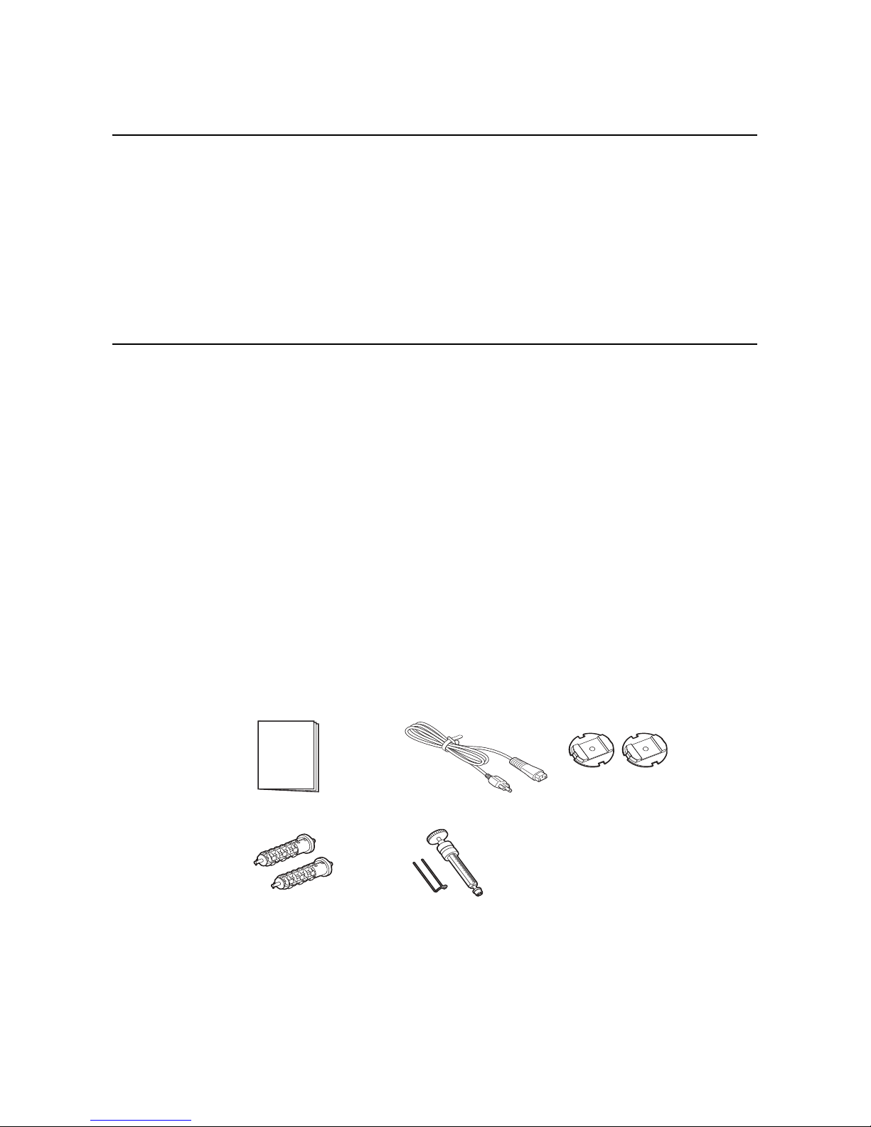
1.2.1 Included Accessories
After unpacking the printer, verify that you have the following materials:
User Documents
(Quick Guide, Warranty, etc)
* The shape of the power plug may vary, depending on the location where it was purchased.
Power plug*
Roll Holders (x2)
Ribbon Adapters (x2)
Core clip, Rewinder
Page 11

Section 1: Introduction
HR2 Series Operator Manual Page 1-3
1.3 PARTS IDENTIFICATION
7
6
1
2
3
4
5
Front view
Operator panel
It consists of six contact buttons and two
LED indicators. Please refer to Section 3.1
Operator Panel.
Top cover
Open this cover to load the media and ribbon.
OPEN button
Press this button to open the Top cover.
Dispenser unit open button
Slide this button downwards to open the cover
of the Dispenser unit.
Label issuing slot
Labels are issued from this slot.
Dispenser sensor sliding knob
To adjust the position of the dispenser sensor.
Power (I/O) switch
Press this switch to turn the power on (I) or
off (O).
1
234
5
6
7
Page 12
Section 1: Introduction
Page 1-4 HR2 Series Operator Manual
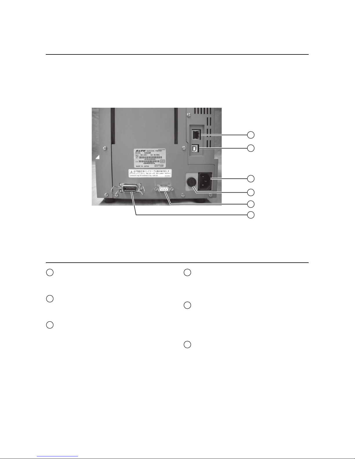
1.3 PARTS IDENTIFICATION (cont’d)
1
2
3
4
5
6
Back view
LAN Interface connector
To connect printer to the host computer using
the LAN interface.
USB Interface connector
To connect printer to the host computer using
the USB interface.
AC IN power terminal
Supplies power to the printer by inserting the
power cable.
Before connection, ensure that the AC voltage
of your region is within the range of AC 100 to
240V, 50/60 Hz.
FUSE (F-400-01A2) holder
Used to hold a fuse which protect the printer
from unstable power supply surge. Use fuse
with rating, 250V/5A -LF (218 005.MXP) only.
RS-232C (DSUB9 pin-female) Interface
connector
To connect printer to the host computer using
the RS232C serial interface.
Or, to connect to the optional SATO keypad.
External connector terminal (EXT)
Interface connector for external signals.
Connect the optional application to this
terminal.
1
2
3
4
5
6
Page 13
Section 1: Introduction
HR2 Series Operator Manual Page 1-5
1.3 PARTS IDENTIFICATION (cont’d)
5
6
7
8
1
2
3
4
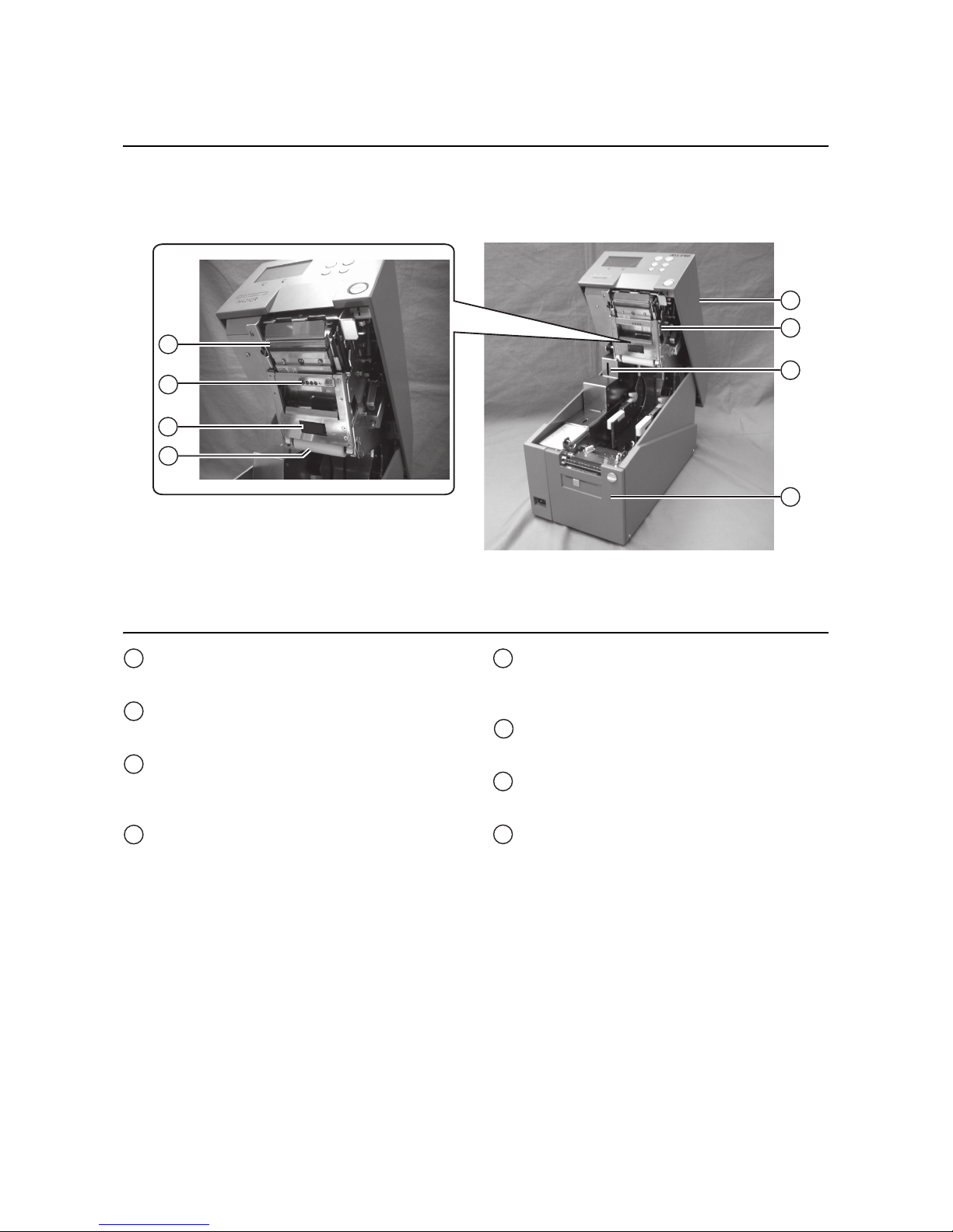
Internal view when Top cover is opened
Top cover
Ribbon unit
A unit for loading ribbon.
SD Card Slot
To insert SD card for additional memory up to
2 GB.
Dispenser unit
A unit to peel off label automatically after
printing.
Print head assembly
This component is used to print on the media.
Perform maintenance at regular intervals.
Label sensor
Used to sense label during printing.
Pinch roller
Used to pinch the roll media.
Guide roller
Roller to guide the roll media.
1
2
3
4
5
6
7
8
Page 14

Section 1: Introduction
Page 1-6 HR2 Series Operator Manual
1.3 PARTS IDENTIFICATION (cont’d)
1
2
3
4
6
5
Internal view when Ribbon unit is opened
Top cover
Ribbon pinch lever
Used to pinch the ribbon.
Ribbon unit
A unit for loading ribbon.
Ribbon unit lever
Press this lever to release ribbon unit from the
top cover.
Ribbon supply shaft bearing
To hold the Ribbon supply shaft.
Ribbon rewind shaft bearing
To hold the Ribbon rewind shaft.
2
3
4
5
6
1
Page 15

Section 1: Introduction
HR2 Series Operator Manual Page 1-7
1.3 PARTS IDENTIFICATION (cont’d)
Media and Rollers Section
6
7
8
1
2
3
4
5
Feed roller
Enable smooth feeding of the label.
Label guide lock lever
Used to lock the label guide.
Label guide
Used to guide the label.
Platen roller
Enable smooth movement of the label during
printing.
Dispenser roller
Enable smooth movement of the label during
dispensing.
Roll shaft bearing
Used to latch roll holder.
Roll media guide lock lever
Used to lock the roll media guide.
Roll media guide
Set to meet the size of the media used.
1
2
3
4
5
6
7
8
Page 16
Section 1: Introduction
Page 1-8 HR2 Series Operator Manual
1.3 PARTS IDENTIFICATION (cont’d)
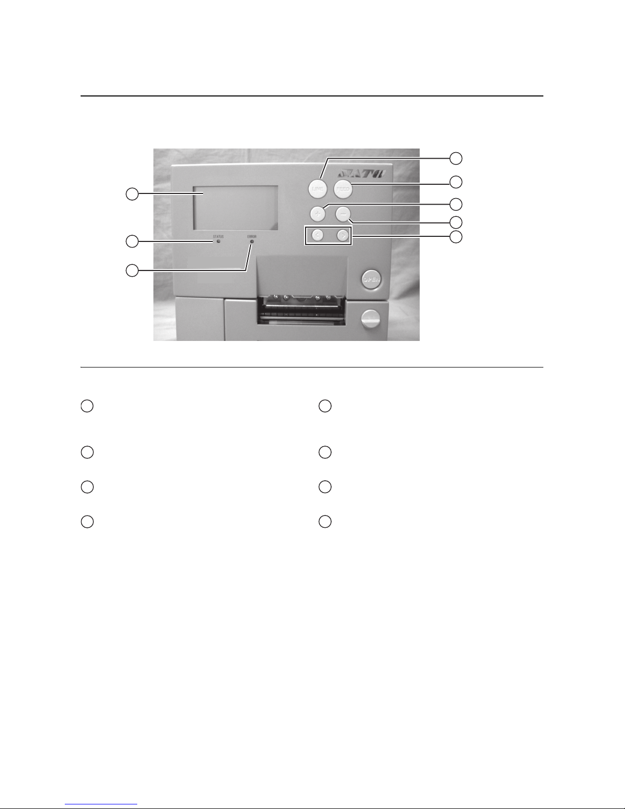
Operating Panel
1
6
7
8
2
3
4
5
LCD screen
Displays various information such as printer
modes and settings.
STATUS LED
Indicates current status of the printer.
ERROR LED
Indicates the printer is in error state.
LINE button
Press this button to toggle between printer
modes or go back to previous setting in various
modes
FEED button
Press this button to start/stop printing or feed
the label.
+ button
Increment value in various modes.
- button
Decrement value in various modes.
Arrow buttons
Press to move the cursor left or right in various
modes.
1
2
3
4
5
6
7
8
Page 17

Section 2: Installation
HR2 Series Operator Manual Page 2-1
INSTALLATION
This section assists you in general printer set up and installing consumable media in the printer, as well as
interface connection with host computer and other optional attachment units.
The following information is provided:
• 2.1 Site Location
• 2.2 Media Selection
• 2.3 Loading Media
• 2.4 Loading the Carbon Ribbon
• 2.5 Removing the Carbon Ribbon
• 2.6 Basic Connections
• 2.7 Connections of optional accessories
• 2.8 LCD Power Saving Mode
Page 18
Section 2: Installation
Page 2-2 HR2 Series Operator Manual
2.1 SITE LOCATION
Consider the following when setting up the printer:
• Place the printer on a solid flat surface with adequate space. Make sure there is enough space above
the printer to provide clearance for the top cover to swing open.
• Place it away from hazardous materials or dusty environments.
• Place it within operational distance of the host computer, within interface cable specifications.
2.2 MEDIA SELECTION
The size and type of the labels to be printed should have been taken into consideration before printer
purchase. Ideally, the media width will be equal to, or just narrower than, the print head. Using media that
does not cover the print head will allow the platen roller to tread on it and wear it out. The media edge will also
wear a groove in the platen roller, which can affect print quality.
This printer can use 2 different types of media, the figures below identifies the media types and their
specifications. The printer uses different sensors to detect the I-Marks or Gap on the media in order to
precisely position the print content.
Note:
For optimal print performance and durability, please use SATO-certified media and ribbon supplies
on this printer. Using supplies not tested and approved for use by SATO can result in unnecessary
wear and damage to vital parts of the printer, and may void the warranty.
10mm
(0.39”)
1.5mm (0.06”)
Gap Label I-Mark Label
3mm
(0.12”)
3mm
(0.12”)
1.5mm (0.06”)
3mm
(0.12”)
76.4mm (3”)
Page 19

Section 2: Installation
HR2 Series Operator Manual Page 2-3
2.3 LOADING MEDIA
2.3.1 To load the label when using the dispenser
1.
Lift up the Top cover while holding down the OPEN button.
Slide down the Dispenser unit open button to open the dispenser unit.
Note:
Make sure that the cover rests firmly so that it will not fall forward and injure your hands.
2. Attach the supplied roll holders to the left and right sides of the roll media respectively.
OPEN button
Dispenser unit
open button
Roll holders
Outer side
Inner side
Page 20

Section 2: Installation
Page 2-4 HR2 Series Operator Manual
2.3 LOADING MEDIA (cont’d)
3.
Release the lock levers of roll media guide and label
guide.
4. Slide the roll media guide to the width of the roll media
and then load the media by latching the Roll media
assembly to the roll shaft bearing.
5. Slide the label guide so that it fits the label width.
After alignment, lock the levers of roll media guide
and label guide.
Notes:
Make sure the media leader is pulled out from the top
and the printed side is facing upwards. Push the roll
firmly towards the end of the roll shaft bearing.
Roll
media guide
lock lever
Roll
media
guide
Label
guide
lock lever
Label
guide
Roll
shaft
bearing
Roll
media
guide
Label
guide
Page 21
Section 2: Installation
HR2 Series Operator Manual Page 2-5
2.3 LOADING MEDIA (cont’d)
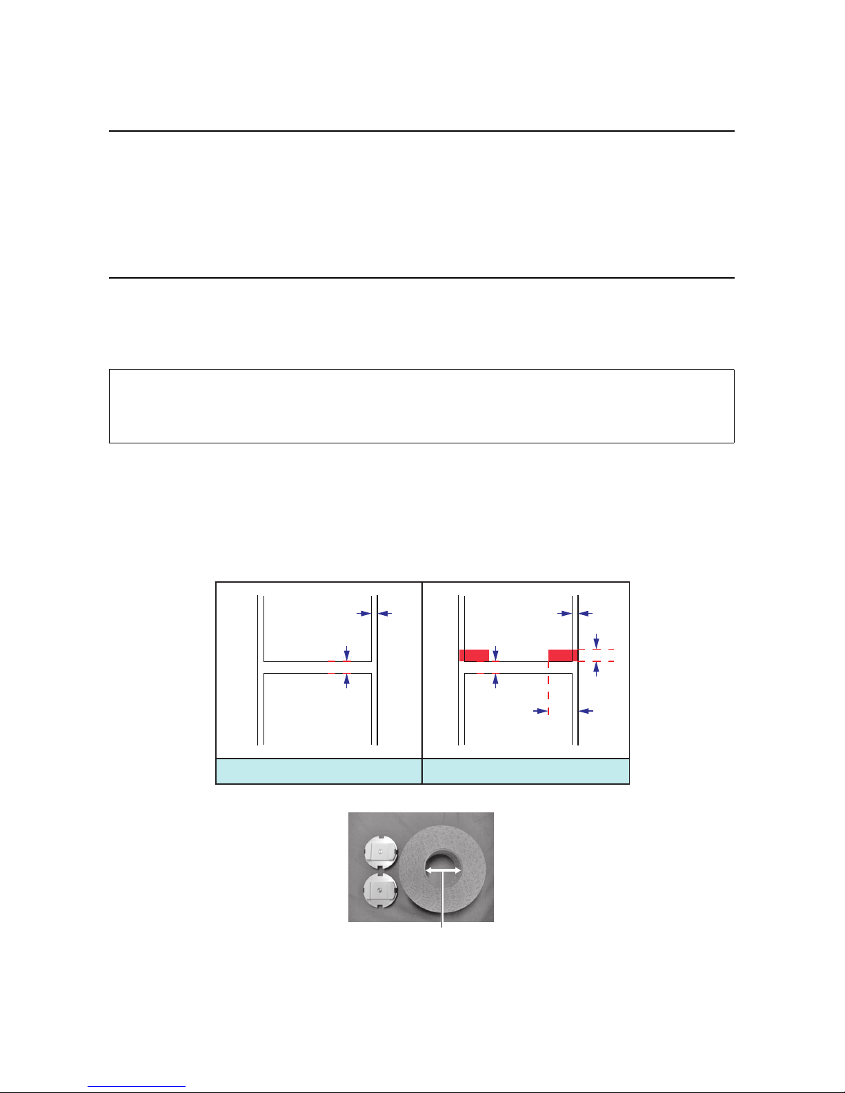
6.
Align the liner (backing paper) by referring to the scale of the rewinder and wrap it to the rewinder in
clockwise direction. Then secure it with the clip.
After clipping, rewind the liner (backing paper) more than 3 turns (150 mm).
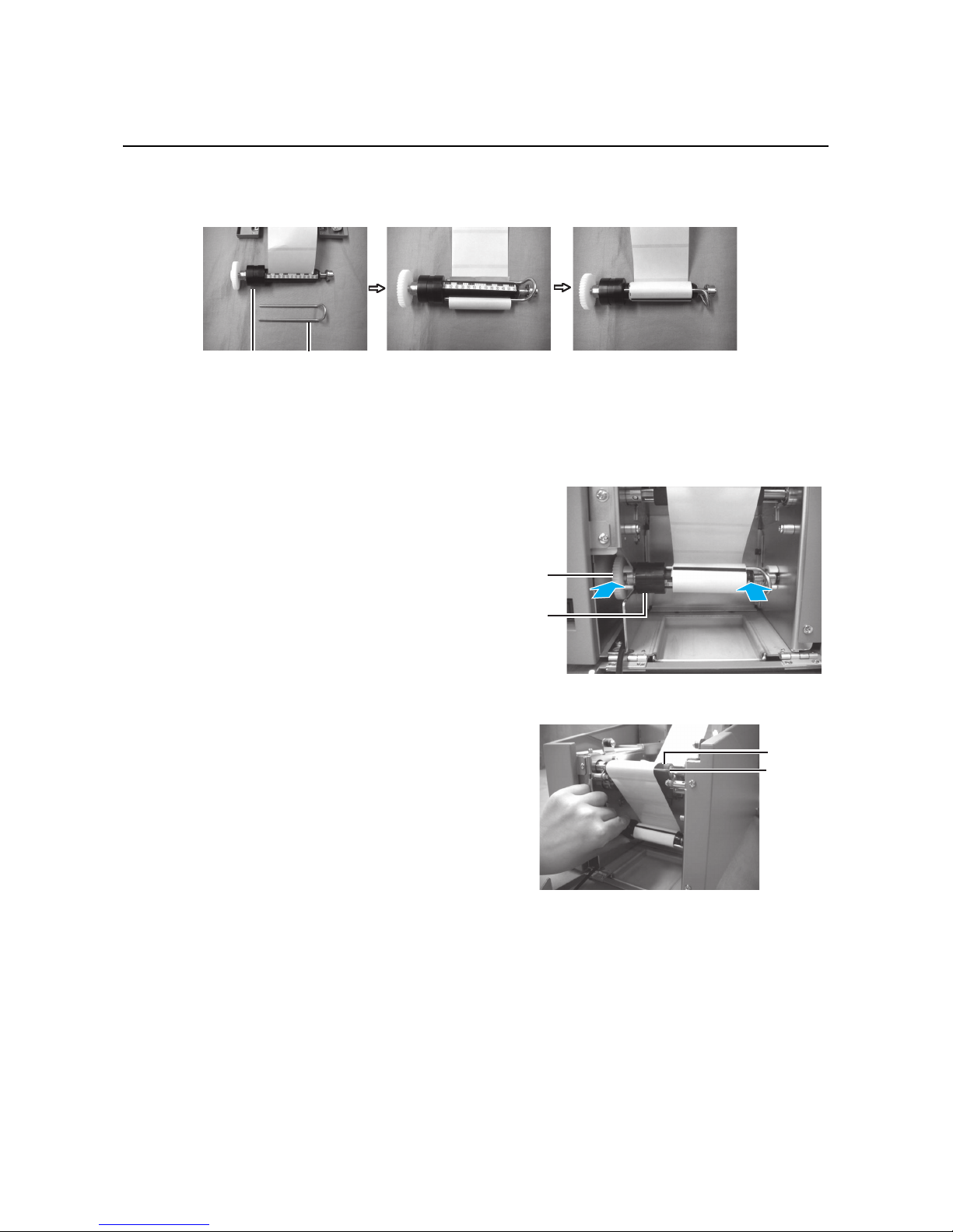
7. Push the rewinder onto the rewinder shaft bearing
until you hear a “tick” sound.
8. Turn the rewinder until the label to be printed
reaches the platen roller.
Rewinder
core
Clip
Rewinder
gear
Rewinder
core
Platen
roller
Dispenser
plate
Page 22

Section 2: Installation
Page 2-6 HR2 Series Operator Manual
2.3 LOADING MEDIA (cont’d)
9.
Close the dispenser unit.
10.If the label is not taut, roll the media in the arrow direction, close the top cover.
You may need to set the Dispenser sensor adjustment. Refer to Section 8.4.2 Adjustment of Stop Position When Using Dispenser/ Tear-off for more details.
Note:
Be careful not to get your fingers caught at the bottom edge when you are closing the top cover.
Caution
• When replacing media, bear in mind that the print head and its surrounding area remain hot.
Keep your fingers away from these areas to prevent injury.
• Avoid touching even the edge of the print head with your bare hands.
Page 23
Section 2: Installation
HR2 Series Operator Manual Page 2-7
2.3 LOADING MEDIA (cont’d)
2.3.2 When operating in continuous mode for the first time
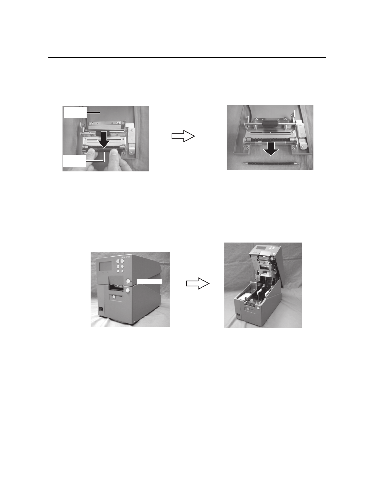
1.
Slide down the Dispenser unit open button to open the dispenser unit.
2. Remove the dispenser roller mounted in the dispenser unit.
While pushing the dispenser roller downwards, pull towards your side to remove it.
Notes:
• Keep the dispenser roller in a safe place.
• Mount with the reversed procedures when you need to issue labels in dispense mode.
3. Close the dispenser unit.
2.3.3 To load the media when operating in continuous mode
1.
Lift up the Top cover while holding down the OPEN button.
2. Load the media. (Refer to steps 2~5 of Section 2.3.1 To load the label when using the dispenser)
3. Close the top cover.
Dispenser
roller
Dispenser
unit
OPEN button
Page 24
Section 2: Installation
Page 2-8 HR2 Series Operator Manual
2.3 LOADING MEDIA (cont’d)
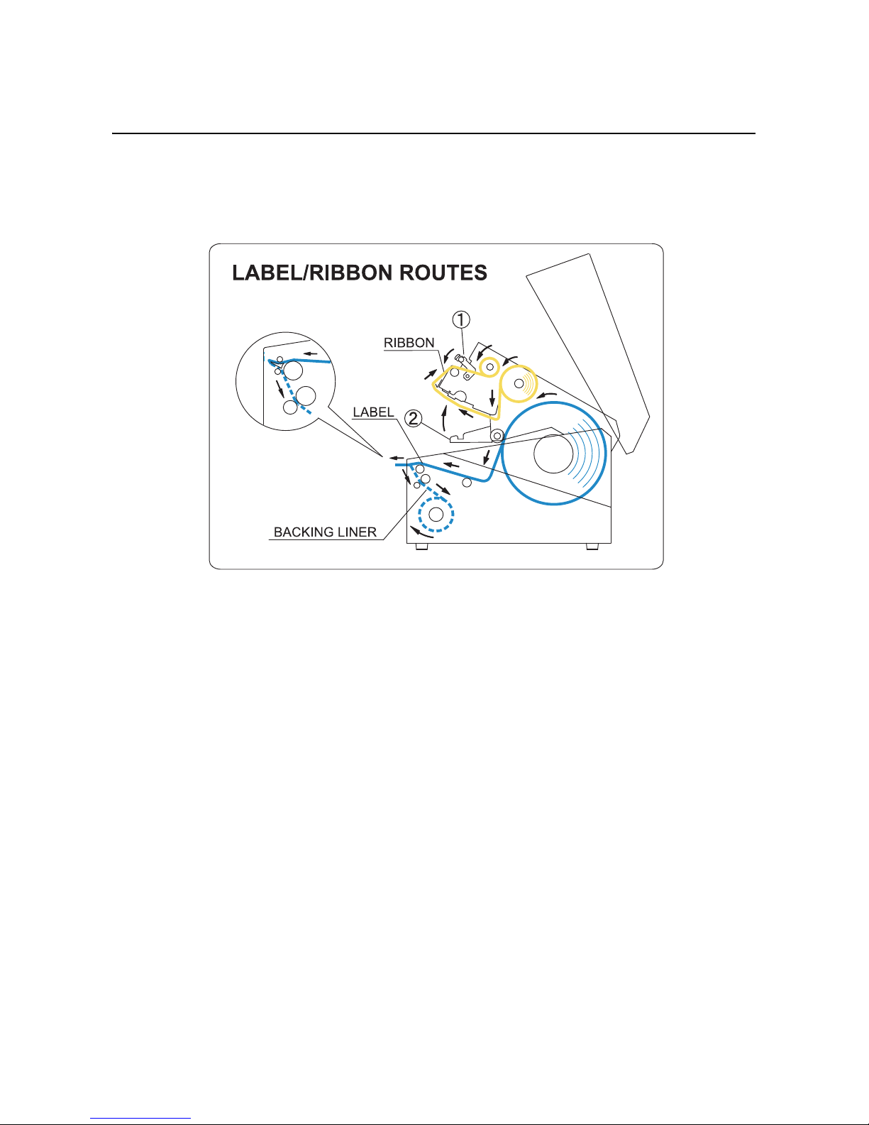
2.3.4 Overview of the media/ ribbon loading path
Note:
You may also refer to the sticker pasted on the inner side of the top cover for the media/ ribbon loading path.
Page 25

Section 2: Installation
HR2 Series Operator Manual Page 2-9
2.4 LOADING THE CARBON RIBBON
The HR2 series printer enables Thermal transfer printing. Thermal transfer paper media requires the use of
carbon ribbon for print application. In such a scenario, it is the carbon ribbon that contains the ink that will be
transferred to the media.
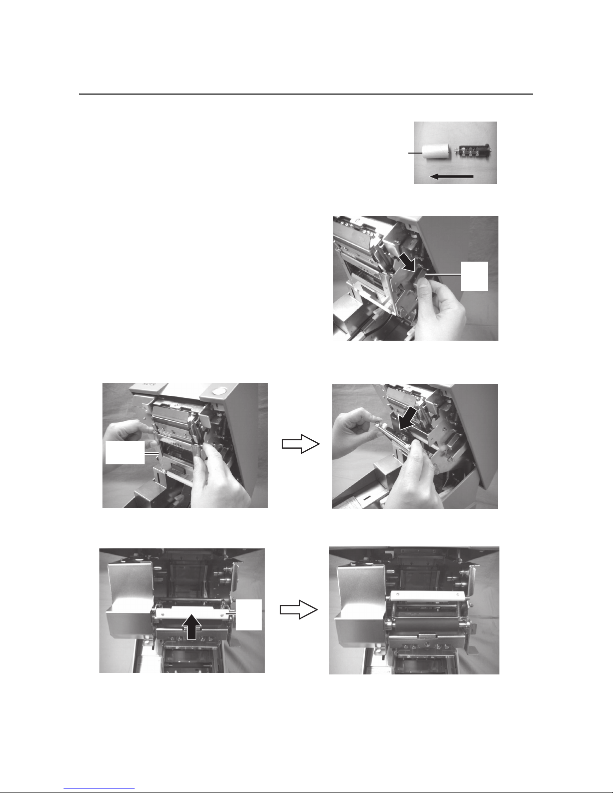
1. Prepare the carbon ribbon and ribbon rewind core.
Use the provided ribbon adapter to load
the carbon ribbon and the ribbon rewind
core.
The position of the ribbon stopper varies
depending on the width of the carbon ribbon.
Example:
When the ribbon width is 65mm
Set the ribbon stopper position to .
2. Insert the ribbon adapter all the way into
the carbon ribbon, while taking note of
the ribbon winding direction.
Caution
• When replacing carbon ribbon, bear in mind that the print head and its surrounding area remain
hot. Keep your fingers away from these areas to prevent injury.
• Avoid touching even the edge of the print head with your bare hands.
Ribbon stopper
Width: 45mm
Width: 65mm
Width: 59mm
Width: 39.5mm
Ribbon adapter
3
1
2
4
Align and turn this mark to position
1
1
Carbon ribbon
winding direction
Insert this way
Page 26
Section 2: Installation
Page 2-10 HR2 Series Operator Manual
2.4 LOADING THE CARBON RIBBON (cont’d)
3.
Insert the ribbon adapter all the way into the ribbon
rewind core.
When loading the carbon ribbon for the first time, use
the empty ribbon rewind core supplied with the
printer. However, the subsequent ribbon core can be
obtained from the last used up ribbon roll.
4. Press the ribbon unit lever to release the ribbon
unit.
Note:
When loading the carbon ribbon, make sure that the
top cover is fully opened.
5. Hold two corners of the pinch roller unit and pull it
in the arrow direction to unlatch.
6. Lift down the ribbon unit and push the ribbon pinch lever upwards.
Ribbon
rewind core
Insert this way
Ribbon
unit
lever
Pinch roller
unit
Ribbon
pinch
lever
Page 27

Section 2: Installation
HR2 Series Operator Manual Page 2-11
2.4 LOADING THE CARBON RIBBON (cont’d)
7.
Load the carbon ribbon from the right side and make sure it latches into the ribbon supply shaft bearing
firmly.
Push in the ribbon shaft assembly to the right side of the ribbon supply shaft bearing. Then fix the other
side of the ribbon shaft assembly to the left of the ribbon supply shaft bearing. Turn the ribbon shaft until
the cross shape shaft snaps on the groove of the left ribbon supply shaft bearing.
Note:
Use only genuine SATO carbon ribbons for maximum print quality and printer durability.
Ribbon supply
shaft bearing
Align to the cross-shape shaft bearing when
latching the ribbon.
Align to the round shape shaft bearing
when latching the ribbon.
Page 28
Section 2: Installation
Page 2-12 HR2 Series Operator Manual
2.4 LOADING THE CARBON RIBBON (cont’d)
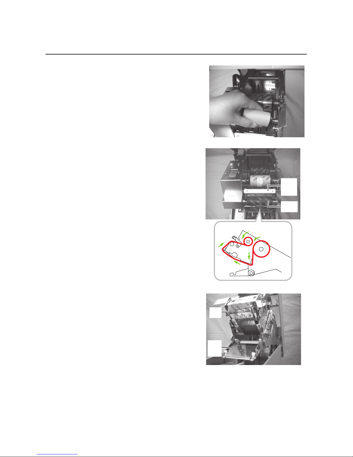
8.
Load the ribbon rewind core to the rewinding side.
The procedures are same as when loading to the supplying
side.
9. From the ribbon supply shaft bearing, pass the carbon
ribbon underneath the print head assembly to the ribbon
rewind shaft bearing.
Route the ribbon between the ribbon pinch lever and
ribbon roller towards the ribbon rewind core. Then route
the ribbon behind and over the top of the ribbon rewind
core. Paste the leader portion of the carbon ribbon onto the
ribbon rewind core.
Ribbon
pinch
lever
Ribbon
roller
Right side view
Print
head
Pinch
roller
unit
Page 29

Section 2: Installation
HR2 Series Operator Manual Page 2-13
10.Turn the rewind shaft bearing several times in the direction
of arrow to wind the ribbon until the ink portion of the ribbon
comes around the ribbon roller.
11. Lift down the ribbon pinch lever back to the ribbon roller
position.
12.Lift up the ribbon unit and remount the pinch roller unit.
Latch the pinch roller unit until you hear a “tick” sound.
Ribbon
pinch
lever
Ribbon
unit
Pinch
roller
unit
Page 30
Section 2: Installation
Page 2-14 HR2 Series Operator Manual
2.4 LOADING THE CARBON RIBBON (cont’d)
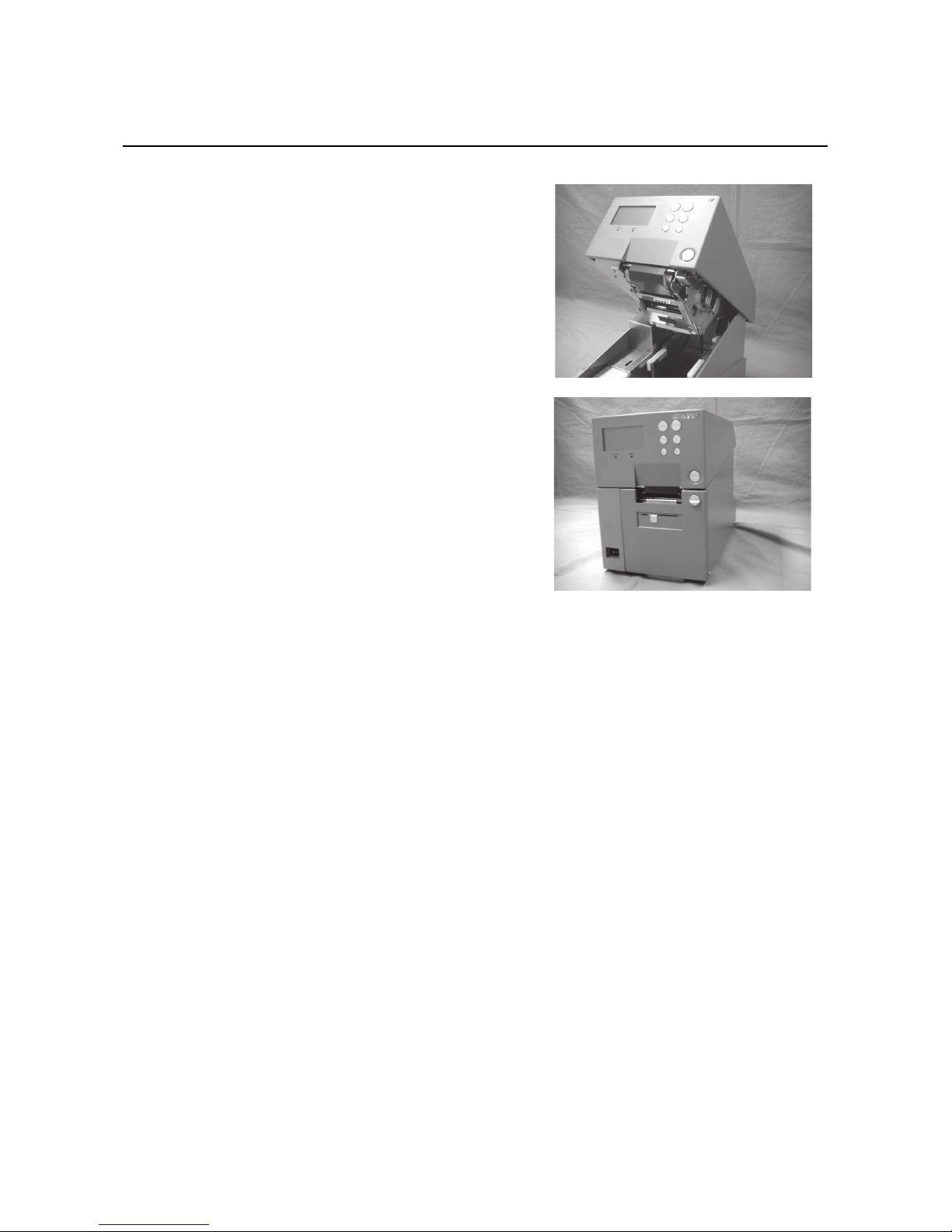
13.
Remount the ribbon unit by pushing it towards the top cover
until you hear a “tick” sound.
14.Close the top cover.
After loading the media and the carbon ribbon, close the
main cover, turn on the printer and do a test print to check
that the media roll has been loaded properly. See Section
3.12 Received Data Saving Mode for instructions on how
to run test print
Page 31

Section 2: Installation
HR2 Series Operator Manual Page 2-15
2.5 REMOVING THE CARBON RIBBON
After the carbon ribbon has used up to the end of the roll, remove the wound-up carbon ribbon from the
printer.
1. With the power supply is off, lift up the top cover and
release the ribbon unit by pressing the ribbon lever.
2. Hold two corners of the pinch roller unit to unlatch it.
3. Lift up the ribbon pinch lever.
Caution
• When replacing carbon ribbon, bear in mind that the print head and its surrounding area
remain hot. Keep your fingers away from these areas to prevent injury.
• Avoid touching even the edge of the print head with your bare hands.
Ribbon
unit
lever
Page 32

Section 2: Installation
Page 2-16 HR2 Series Operator Manual
2.5 REMOVING THE CARBON RIBBON (cont’d)
4.
Push the wound-up carbon ribbon to the right side of the
rewind shaft bearing to remove the ribbon rewind shaft
assembly.
Caution:
Be careful when removing the carbon ribbon, your hands
may get dirty while handling it.
5. Remove the empty core from the ribbon supply shaft in
the same manner.
Note:
Don’t dispose of the empty ribbon core after removing it from the ribbon supply shaft. Instead, transfer it to
the ribbon rewind shaft so that used ribbon can be wound around it after a new ribbon roll has been
loaded.
Page 33

Section 2: Installation
HR2 Series Operator Manual Page 2-17
2.6 BASIC CONNECTIONS
This section explains the power cable and interface cable connection procedures.
2.6.1 Connecting the Interface board
HR2 Series printers are equipped with three different types of standard interface to perform data
communication with the host. These are described as follows.
• USB interface
• LAN interface
• RS-232C (High-speed) interface
Connect interface cable from the printer to the host computer. Use the cable that is compatible with the
standard of the interface board as stated in Section 7: Interface Specifications. Make sure the cable is
correctly oriented before you insert it.
Caution
• Never connect or disconnect interface cables (or use a switch box) with power applied to either
the host or printer. This may caused damage to the interface circuitry in the printer/ host and is
not covered by warranty.
Host
RS232C
USB
LAN
Page 34

Section 2: Installation
Page 2-18 HR2 Series Operator Manual
2.6 BASIC CONNECTIONS (cont’d)
2.6.2 To Configure the Connected Interface
After connection, you need to set the configuration of the connected interface in the INTERFACE MODE
menu of the printer. Please refer to Section 3.7 Interface Mode for details on setting Interface Mode.
In Interface mode, you will need to determine which interface is set as Data Port and which is set as Sub Port.
An overview of each port is shown as below.
Data Port
When the interface is set to the Data Port, it can receive various SBPL commands and it can execute print
operations.
Data port selection: USB, LAN, RS-232C
* The interface which already set for SUB PORT is not able to select.
Sub Port
This port is for monitoring printer status and connecting to external devices.
Sub Port selection: NONE, USB, LAN, RS-232C
* The interface which already set for DATA PORT is not able to select.
Note:
Data Port and Sub Port cannot use the same interface at the same time.
2.6.3 Interface Combination
The interface combinations that can be used for Data Port and Sub Port are as follows.
[o: configurable, x: not configurable]
The following table shows the combination of interface with keypad and the port type.
[o: configurable, x: not configurable]
Data port
RS-232C USB LAN
Sub Port
RS-232C xoo
USB o
xo
LAN o o
x
Condition
Interface
Keypad connection Keypad disconnection
Data Port Sub Port Data Port Sub Port
RS-232C x x o o
USB x o o o
LAN x o o o
NONE x x x o
Page 35

Section 2: Installation
HR2 Series Operator Manual Page 2-19
2.6 BASIC CONNECTIONS (cont’d)
Notes
• Do not select the same interface for the data and sub ports.
• RS-232C and Keypad can't be used at the same time as they use a common connector.
When Keypad is connected, the data port isn't available. Only the sub port is available, but SBPL commands will be disabled.
When the interface other than [RS-232C] is set to the data port, the interface selection changes to [RS232C]. If [RS-232C] is set to the sub port, the interface selection changes to [NONE].
2.6.4 Connecting the Power Cable
1.
Connect the power cable to the AC IN power terminal on
the rear panel of the printer.
Make sure that the connector is correctly oriented.
Secure the printer with one hand, and insert the connector firmly.
2. Insert the power plug into a AC power outlet.
Make sure that the AC voltage of your region is within
the range of AC 100 to 240V, 50/60 Hz.
A 3-pin plug is attached to the power cord provided with
your printer. One of these pins is the ground wire.
If the power outlet that you plan to use is a 3-pin type,
simply insert the power plug as is.
* The shape of the power plug may vary depending on
the location where the printer was purchased.
Warning
• Be sure to connect the ground wire. Failure to do so may cause an electric shock.
• Do not operate the power switch or insert/remove the power cable while your hands are wet.
Doing so may cause an electric shock.
Caution
The power cable provided with this printer are for use with this printer only.
They cannot be used with other electrical devices.
Page 36

Section 2: Installation
Page 2-20 HR2 Series Operator Manual
2.6 BASIC CONNECTIONS (cont’d)
2.6.5 Turning On the Power
Turn on the power switch located on the front, bottom left
corner of the printer.
Press the side of the switch marked “I”.
• When you turn on the power, the printer start-up and
detect for the loaded media and ribbon. If the media are
correctly loaded, “ONLINE” appears on the display.
• If the media and carbon ribbon are not loaded or properly loaded, the printer will prompt an error message.
Load the media and carbon (refer to Section 2.3 Load-
ing Media and Section 2.4 Loading the Carbon Ribbon) and then press LINE button.
2.6.6 Turning Off the Power
When you have completed the printing job, turn the printer
off.
1. Press the LINE button to put the printer offline.
Be sure to confirm that the printer is in the offline status
before turning it off.
If there is any printed media remaining in the printer,
press FEED button to forward feed the media and cut it
off.
2. Turn off the power switch on the printer’s operation
panel.
Press the side of the switch marked “O”.
Warning
Do not operate the power switch or insert/remove the power cable while your hands are wet.
Doing so may cause an electric shock.
On Off
On
Off
Page 37

Section 2: Installation
HR2 Series Operator Manual Page 2-21
2.7 CONNECTIONS OF OPTIONAL ACCESSORIES
2.7.1 Connecting optional Keypad
The optional keypad can be connected to the HR2 Series printer with the RS-232C terminal, thus providing a
stand-alone function.
1. Make sure that power cable is not connected to the
printer.
2. Connect the cable from the optional Keypad device to
the RS-232C terminal at the rear of the printer.
Note:
Make sure the connector is correctly oriented. Secure
the printer with one hand, and insert the connector firmly.
3. Set the printer for use with the connected device. Refer
to Section 3.7 Interface Mode and perform the
procedures to set the Keypad CONNECT to ENABLE.
4. Then set the DATA PORT as RS-232C and the SUB
PORT as NONE.
Notes:
• Keypad needs to connect to RS-232C connector, and RS-232C interface are not able to use as data port
at the same time.
• You cannot use data port when Keypad is connected and the setting of Keypad connection is valid. (You
can use Sub Port, but SBPL command is not effective.)
2.7.2 Installing optional Memory storage
The optional SD card can be used for uploading and downloading the data (graphics, extended character)
registered in the printer and the printer firmware.
Installing optional SD card
You can connect the optional SD card to the SD card slot
located as shown in the picture.
SD card slot
Page 38

Section 2: Installation
Page 2-22 HR2 Series Operator Manual
2.7 CONNECTIONS OF OPTIONAL ACCESSORIES (cont’d)
1.
Insert the SD card with the orientation as shown in the picture.
2. To seat the SD card in the slot, press it in until it makes a
slight clicking sound and it is completely inside the printer.
3. To remove the SD card from the printer, it is best to switch
off the printer. Then, with your finger, press the card edge a
slight amount to release the card from the slot. The slot will
immediately release the card.
Note:
Do not remove the SD card while the printer is accessing the
data in the SD card. Doing so may result in data corruption.
Page 39

Section 2: Installation
HR2 Series Operator Manual Page 2-23
2.7 CONNECTIONS OF OPTIONAL ACCESSORIES (cont’d)
Folder Configuration
The following is the folder architecture inside the SD card to be used for the printer.
DATA
PROG
FONT
Firmware
Firmware : PRG41_XX.BIN (XX : Reg. No. 01 to 03)
SEMBL Program㸸SEMBL.BIN
Data for memory card command
Form overlay registration 㸸SBPLXXXX.OVL (XXXX : Reg. No.0001 to 0099)
Format registration : SBPLXXXX.FMT (XXXX : Reg. No. 0001 to 0999)
Graphic registration: SBPLXXXX.IMG (XXXX : Reg. No. 0001 to 0999)
BMP file registration : SBPLXXXX.BMP (XXXX : Reg. No. 0001 to 0999)
PCX file registration : SBPLXXXX.PCX (XXXX : Reg. No. 0001 to 0999)
Memory card 16x16 Extended character registration : SBPL16.BMF
Memory card 24x24 Extended character registration : SBPL24.BMF
PR41
SD card route
Download font / log
Download font data : USRFONTX.DAT(X : Reg. No. (1 to 6))
CONF
Printer configuration information
Printer configuration information file : PRN41.INI
RAS
Rasterized font
No corresponding files for HA200R/HR200
LOG
Maintenance
Receive buffer: RCVBUF.DAT
STATUS5 log : HISTSTS5.DAT
FRAM dump:FRAMDMP.DAT
Page 40

Section 2: Installation
Page 2-24 HR2 Series Operator Manual
2.7 CONNECTIONS OF OPTIONAL ACCESSORIES (cont’d)
Notes:
• In the folder architecture, the folders under [PR41] can be created by formatting the SD card in Memory
Card Mode.
- Be sure to format the SD card in Memory Card Mode. If formatting the SD card by Windows or other
methods, you may not be able to save or view the data.
- Attempting to download or upload the data without formatting the SD card properly will cause an
error preliminarily.
• Do not change file name and folder names under the folder [PR41].
• Inside the folders [PROG] and [FONT], if you save files other than released (or uploaded) firmware and
font files, the printer motion after download behavior or download may be unstable. Be sure not to save
any files unless they are released (or uploaded).
• Do not remove the SD card while the printer is accessing the SD card. Doing so may result in data corruption.
• When you save the data to the SD card by using the save-related SBPL commands, its file creation date
will be the firmware release date.
2.8 LCD POWER SAVING MODE
The LCD backlight is turned off for power saving when the printer is not operated for a specified period of
time. The time to turn off the LCD backlight can be set via the LCD POWER SAVING MODE SETTING screen
in the Advanced Mode. Please refer to Section 3.10 Advanced Mode for instructions.
2.8.1 Turning off the LCD Backlight
At the following conditions, the LCD backlight is turned off when the time specified on the LCD POWER
SAVING MODE SETTING screen has elapsed. In this function, only the LCD backlight is turned off and the
on-screen message remains the same.
• The printer has not received the print data (ESC+A~ESC+Z) in various interfaces.
* Omitting status return request and cancel request of each protocol and/or incorrect data.
• No button is pressed.
• The printer is not in error state.
• The printer is neither printing nor feeding paper.
• The printer is in online state, offline state, HEX dump mode or SEMBL mode.
* This function is disabled in the Download Mode.
2.8.2 Turning on the LCD Backlight
Following one of the instructions below will turn on the LCD backlight again.
• The printer received the print data from various interface boards.
* Omitting status return request and cancel request of each protocol and/or incorrect data.
• Some buttons are pressed.
• Printer error such as “Cover open” occurred.
• The printer started printing operation.
Pressing any button while the LCD backlight is off will turn on the LCD backlight only.
(The printer does not go offline by pressing the LINE button when the LCD backlight is off in online state.)
Page 41

Section 3: Operation and Configuration
HR2 Series Operator Manual Page 3-1
OPERATION AND CONFIGURATION
Before using the printer, it is best to read this manual thoroughly first. Otherwise, you may disturb default
settings around which the instructional procedures in this manual are based upon.
The printer may be manually configured via the LINE, FEED, +, -, < and > buttons with the LCD display on the
operator panel of printer. All of the printer’s buttons are used either singularly, or in conjunction, to perform
configuration activities.
Many of these settings can also be controlled via software commands and in case of conflict between
software and control panel settings, the printer will always use the last valid setting. If you load a label job that
includes software settings and then enter a new setting via the LCD panel, the manually set values will be
used by the printer. If you set the values manually and then download a job with software settings, the
software settings will be used.
Page 42

Section 3: Operation and Configuration
Page 3-2 HR2 Series Operator Manual
3.1 OPERATOR PANEL
The operator panel locate on the front consist of two LED indicators, six momentary contact buttons and one
LCD display.
•LED indicators
When the printer is in normal mode, these two indicators notify the user of various status conditions:
• LINE button
Pressing this button toggles the printer between the online and offline mode. When the printer is online, it
is ready to receive data from host. This button acts as a pause during a print job by taking the printer
offline.
This button also function as returning to the previous item during various printer setting with the LCD display.
When performing long press during various printer setting, the screen will go back to [Mode Menu] directly.
• FEED button
Pressing this button feeds one blank label through the printer.
This button also function as determining the setting during various printer setting with the LCD display.
• + button
Incrementing setting value in various setting modes, or moving cursor up/down in menus.
Makes the LCD display darker in Online state.
• - button
Decrementing setting value in various setting modes, or moving cursor up/down in menus.
Makes the LCD display lighter in Online state.
• <, > arrow buttons
These cause the cursor to shift left and right for selecting item on the screen in various setting modes.
LED Indicator Color Functions
STATUS Green Illuminates when printer is ready to receive data or is in printing
mode (Online).
Light is off when the printer is in offline or error state.
Blinks when the printer detects buffer near full.
ERROR Red Illuminates or blinks when detecting printer error.
(5525
67$786
+
-
㸺
/,1(
)(('
㸼
Page 43

Section 3: Operation and Configuration
HR2 Series Operator Manual Page 3-3
3.1 OPERATOR PANEL (Cont’d)
• LCD Display
Up to five icons and two lines of alphanumeric text can appear on the LCD display to indicate the current
printer status.
The same area can also display two lines of alphanumeric text during various setting modes.
List of Icons
[Mode display]
[Mode selection screen]
No Icon Description
1 Displayed when printer is in online state
2 Displayed when printer is in offline state
3 Displayed when printer is in Test Print Mode and HEX Dump Print Mode
4 Displayed when printer is in SEMBL Mode
5 Displayed when printer is in Download Mode
6 Displayed when Keypad is connected to printer
7 Displayed when printer is in Upload Mode
No Icon Description
1 Changing to Normal Mode
2 Changing to User Mode
3 Changing to Interface Mode
4 Changing to Cartridge Mode (Memory Card Mode)
5 Changing to SEMBL Mode
6 Changing to Advanced Mode
7 Changing to HEX Dump Print Mode
Page 44

Section 3: Operation and Configuration
Page 3-4 HR2 Series Operator Manual
3.1 OPERATOR PANEL (Cont’d)
List of Icons (Cont’d)
[Error-related]
[Warning-related]
No Icon Description
1 Displayed when detecting Label End
2 Displayed when detecting Ribbon End
3 Displayed when detecting Sensor Error
4 Displayed when detecting Top cover open and head lift error
5 Displayed when detecting electrical disconnection of print head
6 Displayed when detecting Communication Error
7 Displayed when detecting Receive Buffer Over
8 Displayed when detecting Item No. Error or BCC Error
9 Displayed when having write failure to main ROM or when detecting Kanji
ROM error
10 Displayed when detecting a command error due to the message display func-
tion of command error
11 Displayed when detecting an improper download data
12 Displayed when having a memory access error or when running out of mem-
ory space
13 Displayed when detecting printer error other than the above
14 Error number corresponding to each error
No Icon Description
1 Displayed when detecting Command Error
2 Displayed when detecting Receive Buffer Near Full
3 Displayed when detecting electrical disconnection of print head
Page 45

Section 3: Operation and Configuration
HR2 Series Operator Manual Page 3-5
3.2 OPERATING MODES
The operating status of this printer can be set within one of the following modes:
1. Normal mode (including ONLINE/OFFLINE modes)
2. Adjustment screen
3. Cancel Print Job mode
4. Printer Setting mode:
• User mode
• Interface mode
• Cartridge mode (Memory Card mode)
• SEMBL mode
• Advanced Mode
•Hex Dump mode
5. Test Print mode
6. Default Setting mode
7. Maintenance mode
8. Service mode
9. Download mode
10.Upload mode
The various modes are accessed by pressing the LINE button, FEED button, + button, - button and <, > arrow
buttons while the printer is Off, On or with certain printer settings in force.
Page 46

Section 3: Operation and Configuration
Page 3-6 HR2 Series Operator Manual
3.2 OPERATING MODES (Cont’d)
The following flow chart provides a clear summary of all the modes and their access methods.
Switch Power
to On “ I ”
Power off
+ & < button
<, >, +, - buttons
<, >, +, - buttons
<, >, +, - buttons
<, >, +, - buttons
<, >, +, - buttons
<, >, +, - buttons
Menu screen
FEED
button
User Mode
FEED
button
Interface Mode
FEED
button
SEMBL Mode
FEED
button
Advance Mode
FEED
button
HEX Dump
Mode
FEED
button
Cartridge Mode
Mode
Adjustment
screen
Cancel print
job
< & > buttons
LINE &
FEED buttons
More operations are shown on the next page.
Online state
+
-
+
-
+
-
+
-
+
-
+
-
+
-
Offline state
LINE
button
63((' &
'$5.1(66 $
3,7&+
2))6(7
+
-
Page 47

Section 3: Operation and Configuration
HR2 Series Operator Manual Page 3-7
3.2 OPERATING MODES (Cont’d)
FEED &
Power on
Power off
Test print Mode
LINE &
FEED &
Power on
+ & - &
Power on
Default setting
Mode
Maintenance
Mode
Download
Mode
Service Mode
Select SERVICE
MODE &
FEED button
&
Power on
FEED & &
& Power on
Upload
Mode
+ & - & < & Power on
*English LCD message in maintenance mode
Page 48

Section 3: Operation and Configuration
Page 3-8 HR2 Series Operator Manual
3.3 ONLINE AND OFFLINE MODES
The general and basic operation of the HR2 series printer is via the Normal mode, which consists of the
ONLINE and OFFLINE modes.
3.3.1 Online Mode
Pressing the LINE button causes the printer to go ONLINE or OFFLINE
alternately.
When the printer is ONLINE, the following activities will be possible:
• The printer is ready to receive print data from the computer or other connected devices
• The printer is ready to start printing
The number displayed on the bottom line of LCD panel shows the media
quantity status. As soon as a print job is received, the display on the bottom
will indicate the number of labels to be printed. When the label job begins to
print, this display will indicate the remaining number (countdown) of labels to
be printed.
Display method can be changed on the TOTAL QTY DISPLAY screen in the
service mode, refer to Section 3.16.5 Overview of Setting menu in Service
Mode for details.
When the TOTAL QTY DISPLAY screen is set as YES, the number displayed
on the bottom line of LCD panel shows the remaining number (countdown) of
labels to be printed on the left and the total quantity on the right (Total print
quantity from the time the printer is turned on).
3.3.2 Offline Mode
When the printer is ONLINE, pressing the LINE button once will cause the
printer to go OFFLINE. Any printing job will be PAUSE once the printer is
brought OFFLINE.
When the printer is OFFLINE, the activities for ONLINE mode are no longer
possible, but the following activities will be possible:
• The printer can feed a blank label when you press the FEED button.
• The printer can be switched to CANCEL PRINT JOB modes when you
press the LINE and FEED button simultaneously.
• The printer goes to Adjustment screen when you press the and arrow buttons simultaneously.
• In OFFLINE mode, press the + and buttons simultaneously to access the icon-based printer settings
menu. Using the arrow buttons, you can access the ONLINE mode, USER mode, INTERFACE mode,
SEMBL mode, ADVANCED mode, HEX DUMP mode and CARTRIDGE mode from here. These modes
will be discussed in subsequent sections.
3.3.3 To Adjust the Screen Contrast
In Normal mode (ONLINE or OFFLINE), press the +/- buttons repeatedly to adjust the contrast.
remaining number
(countdown) of
labels to be printed
total printed
quantity
remaining number
(countdown) of
labels to be printed
When TOTAL QTY DISPLAY is set
as YES (Default)
When TOTAL QTY DISPLAY is set
as NO
remaining number
(countdown) of
labels to be printed
total printed
quantity
Page 49

Section 3: Operation and Configuration
HR2 Series Operator Manual Page 3-9
3.4 ADJUSTMENT SCREEN
The printer has a quick access to the Adjustment screen for setting the print position, stop position and the
print darkness. These adjustments are in conjunction with the configuration adjustments done in the Service
mode menu and the User mode menu.
1. When the printer is OFFLINE, pressing both the and arrow buttons at the same time will switch the
printer to Adjustment mode. The setting screen is displayed.
2. Press +/- buttons to set the desired value and press FEED button to save the setting and proceed to the
next Adjustment screen.
3. After adjustment, press LINE button to exit the Adjustment screen and returns to OFFLINE mode.
Pressing the LINE button before pressing the FEED button will not save the adjustment.
You may wish to print a test print after completing the adjustments to ensure they are correct. Refer to
Section 3.13 Test Print Mode for details.
Press FEED button
Press & button
* Press + or - button to set the value.
63((' &
'$5.1(66 $
3,7&+
2))6(7
+
-
63(('
'$5.1(66 $
3,7&+
2))6(7
&
63(('
'$5.1(66 $
3,7&+
2))6(7
+
-
&
63(('
'$5.1(66 $
3,7&+
2))6(7
+
-
&
Press FEED button
+
-
Press FEED button
63(('
'$5.1(66 $
3,7&+
2))6(7
+
-
&
63(('
'$5.1(66 $
3,7&+
2))6(7
+
-
&
Press FEED button
Press FEED button
QTY=0
47<
&
Press FEED button
Press LINE button
Press LINE button
Press LINE button
Press LINE button
Press LINE button
Press LINE button
Page 50

Section 3: Operation and Configuration
Page 3-10 HR2 Series Operator Manual
3.4 ADJUSTMENT SCREEN (Cont’d)
Menu Description
Adjust the print speed.
Setting range is between 1.0 and 4.0IPS, and the initial value is 2.0IPS.
This setting reflects the setting of PRINT SPEED screen in USER MODE.
Command priority setting.
C: Enables Command priority setting.
I: Disables Command priority setting.
The default setting is "C".
This setting reflects the setting PRIORITY SETTING screen in SERVICE
MODE.
Adjust the print darkness of the print-out.
Setting range is 1A, 2A, 3A, 4A, 5A, 1B, 2B, 3B, 4B, 5B. (1A is the lightest
while 5B is the darkest. Default is “3A”)
This setting reflects the setting of PRINT DARKNESS screen in USER
MODE and the DARKNESS RANGE screen in ADVANCED MODE.
Setting value of the selected range is between 00 and 99, and the initial
value is 50. (00 is the lightest while 99 is the darkest.)
After setting the value of print darkness, press FEED button will save the
value and proceed to PITCH position setting if there is no remaining label to
be printed. (QTY=0)
Otherwise, the printer will return to SPEED setting screen. (QTY≠0)
Note:
It is not advisable to set the print darkness to the higher position as a darker
print-out requires the print head to operate in a higher temperature. Operating in high temperature may damage the print head in a long run.
Adjusts the print position or reference point where the printings begins vertically, relative to the leading edge of each media.
Setting value is adjustable by 0.25mm (0.01") regardless of print resolution.
Setting range is ±3.75mm (±0.15") and the initial value is +0.00mm.
Adjust the stop position of each media after printing.
Setting value is adjustable by 0.25mm (0.01") regardless of print resolution.
Setting range is ±3.75mm (±0.15") and the initial value is +0.00mm.
63((' &
'$5.1(66 $
3,7&+
2))6(7
+
-
63(('
'$5.1(66 $
3,7&+
2))6(7
+
-
&
63(('
'$5.1(66 $
3,7&+
2))6(7
+
-
&
63(('
'$5.1(66 $
3,7&+
2))6(7
+
-
&
63(('
'$5.1(66 $
3,7&+
2))6(7
+
-
&
63(('
'$5.1(66 $
3,7&+
2))6(7
+
-
&
Page 51

Section 3: Operation and Configuration
HR2 Series Operator Manual Page 3-11
3.5 CANCEL PRINT JOB MODE
1. When the printer is OFFLINE, pressing both the LINE and FEED buttons at the same time will switch the
printer to CANCEL PRINT JOB mode. The menu for canceling the print job then appears.
2. Press , arrow buttons to switch between the selection, YES or NO. The highlight on display indicates
the selected option. The default setting is NO.
If the printer has a print job in memory, selecting YES will cause the job to be cleared.
Notes:
• Be sure you want to cancel the print job before selecting YES as the job cannot be recovered and will
have to re-transmit to the printer.
•Select NO press FEED button to exit the CANCEL PRINT JOB mode without clearing the print data.
3. Press FEED button to activate the selection.
If YES is selected, the message CANCEL PRINT JOB COMPLETED will display with 3 beeps sound and
then goes to ONLINE mode. All the print jobs were cleared from memory.
Select “YES” +
FEED button
3 beep sound
LINE + FEED
buttons
Select
“NO” +
FEED button
Page 52

Section 3: Operation and Configuration
Page 3-12 HR2 Series Operator Manual
3.6 USER MODE
The following settings are available in the User Mode.
FEED button
FEED button
FEED
button
LINE
button
FEED
button
LINE
button
FEED
button
LINE
button
FEED
button
LINE
button
FEED
button
LINE
button
Displayed only when entry
of PASSWORD is enabled
Return to USER MODE menu
* Press <, >, + or - button to select
item or set the value accordingly.
The active arrow icons are displayed
on the screen.
+
-
+
-
+
-
+
-
FEED
button
LINE
button
Press and hold
LINE button
Press and hold
LINE button
Press and hold
LINE button
Press and hold
LINE button
Press and hold
LINE button
Press and hold
LINE button
Page 53

Section 3: Operation and Configuration
HR2 Series Operator Manual Page 3-13
3.6 USER MODE (Cont’d)
1. During OFFLINE mode, press + and < button simultaneously to display the operational icon menu. Press
<, >, + or - buttons to select USER MODE.
2. When USER MODE screen is displayed, press the FEED button to enter to User mode for adjustment.
Note:
PASSWORD may prompt on the display if SET PASSWORD is set to ON in the Service mode. Please
refer to Section 3.16.5 Overview of Setting menu in Service Mode for details in password inputting.
3. PRINT SPEED is first displayed. Press the FEED button repeatedly will switch to the next setting options
as shown above. To return to the previous setting option, press LINE button.
4. When the desired setting option is displayed, press <, >, + or - buttons to select the item or to set the value
and then press FEED button to save the setting. To return to USER MODE screen, press and hold LINE
button.
You may wish to print a test print after completing the adjustments to ensure they are correct. Refer to
Section 3.13 Test Print Mode for details.
USER MODE
Menu Description
Adjusts the print speed that does not compromise print quality.
Setting range is between 1.0 and 4.0 IPS (inches per second) with a increment
of 0.5 IPS cyclically. The initial value is 2.0 IPS.
This setting adjusts the print darkness of the print-out with reference to the setting of the DARKNESS in Adjustment screen.
Setting value can be set from 1 (lightest) to 5 (darkest). The default setting is 3.
Print Position Offset—which refers to the vertical and horizontal shifting of the
entire print area, relative to the start position of printing (V=0, H=0), defined by
default to be the bottom right hand corner of the media.
The V setting is for the Vertical print offset. A positive (+) offset means the printing is shifted towards the print head; a negative (-) offset means shifting away
from the print head. If the PITCH POSITION setting has been used to offset the
vertical start position, then all Vertical offset adjustments are made relative to
that start position.
The H setting is for the Horizontal print offset. The + or - prefix determines
whether the offset is to the left or to the right of the reference point.
Setting value is indicated by dot, and the initial value, regardless of print resolution, is V:+0000 H:+0000.
Setting range differs by print resolution.
[12dots/mm] :V:±0 to 2400 H:±0 to 672
[24dots/mm] :V:±0 to 4800 H:±0 to 1344
+
-
+
-
Print
direction of label
ref point
HH-
V+
Print
V-
Page 54

Section 3: Operation and Configuration
Page 3-14 HR2 Series Operator Manual
3.6 USER MODE (Cont’d)
USER MODE
Menu Description
You can use this setting to determine whether zeroes are printed with a slash
across them or not. The zero slash can be set to either 0 or Ø.
If YES, [0] will be accompanied by a slash.
If NO, no slash will appear.
The initial value is NO.
* Slash zero (zero has a slash through it) is available in the following fonts:
U, S, M, WB, WL, XU, XS, XM, XB, XL, Outline font
Allows you to select character code from the following:
“JIS”: Uses JIS for Kanji code.
“SJIS”: Uses Shift JIS for Kanji code.
“Unicode”: Used Unicode for Kanji code.
The default is “JIS”.
This setting determines whether the space surrounding each text character is
of a fixed width, or whether that space is to be varied to be visually more pleasant and proportional.
If selecting PROPORTIONAL, data will be printed without character spacing.
If selecting FIXED, data will be printed with fixed character spacing.
The initial value is FIXED.
FIXED
Page 55

Section 3: Operation and Configuration
HR2 Series Operator Manual Page 3-15
3.7 INTERFACE MODE
In this mode, you can set various parameters governing the use of interface cards.
3.7.1 Overview of Interface Mode Configurations
FEED button
FEED
button
LINE
button
FEED
button
LINE
button
Setting contents differ by selected I/F
To the setting of LAN
To the setting of RS-232C
To the setting of USB
LINE
button
Select NO +
FEED button
Select
YES +
FEED
button
LINE
button
Displayed only when entry
of PASSWORD is enabled
Return to INTERFACE MODE menu
* Press <, >, + or - button to select
item or set the value accordingly.
The active arrow icons are displayed
on the screen.
+
-
+
-
FEED
button
LINE
button
Select DATA
PORT +
FEED button
LINE
button
Select SUB
PORT +
FEED button
121(
FEED
button
LINE
button
FEED
button
Press and hold
LINE button
Press and hold
LINE button
Press and hold
LINE button
Press and hold
LINE button
Displayed only in the
case of SUB PORT
Page 56

Section 3: Operation and Configuration
Page 3-16 HR2 Series Operator Manual
3.7 INTERFACE MODE (Cont’d)
1. During OFFLINE mode, press + and < button simultaneously to display the operational icon menu. Press
<, >, + or - buttons to select INTERFACE MODE.
2. When INTERFACE MODE is displayed, press the FEED button to enter to Interface mode for adjustment.
Note:
PASSWORD may prompt on the display if SET PASSWORD is set to ON in the Service mode. Please
refer to Section 3.16.5 Overview of Setting menu in Service Mode for details in password inputting.
3. Keypad CONNECT is first displayed. Press the FEED button repeatedly will switch to the next setting
options as shown above. To return to the previous setting option, press LINE button. To return to INTERFACE MODE screen, press and hold LINE button.
4. When the desired setting option is displayed, press <, >, + or - buttons to select the item or to set the value
and then press FEED button to save the setting.
INTERFACE MODE
Menu Description
This screen shows the connection setting of input device (Keypad).
ENABLE: If the input device is connected, print data from the device will be
valid. If the device is disconnected, print data received from the PC
will be valid.
* The data received from the PC becomes invalid while the input
device is connected.
DISABLE: Only the print data received from the PC becomes valid.
* The data received from the input device becomes invalid.
The initial cursor position is at ENABLE.
Connection status of input device can be checked by the status icon displayed
in the Normal Mode (ONLINE/ OFFLINE).
Note: Changed settings will be in effect from the next power on.
This is a confirmation screen for setting the connected interface configurations.
If YES, it goes to the PORT SELECT screen.
If NO, it returns to INTERFACE MODE menu.
The initial cursor position is at NO.
This screen allows user to select the port used for the connected interface.
Either DATA PORT or SUB PORT can be selected.
DATA PORT: It can receive various SBPL commands and it can execute print
operations.
SUB PORT: It is for monitoring printer status and connecting to external
devices.
The initial cursor position is at DATA PORT.
Select the connected interface to be used as Data Port.
One of three interfaces, LAN, RS-232C, USB can be selected. The initial cursor position is at LAN.
Notes:
•You can’t select the data port when Keypad is connected to RS-232C.
•The interface which already set for SUB PORT is not able to select.
Restart the printer to enable the new settings.
Page 57

Section 3: Operation and Configuration
HR2 Series Operator Manual Page 3-17
3.7 INTERFACE MODE (Cont’d)
INTERFACE MODE
Menu Description
Select the connected interface to be used as Sub Port.
NONE, RS-232C, USB or LAN can be selected. The initial cursor position is at
NONE.
Notes:
•The interface which already set for DATA PORT is not able to select.
Restart the printer to enable the new settings.
This screen shows the connection setting between the Sub Port and the external device.
ENABLE: Connecting the sub port and the external device. It’s possible to
import the data from the external port into the print data by the combination of
an extended command.
DISABLE: Not connecting the sub port and the external device. It’s possible to
monitor the printer status.
The initial setting is ENABLE.
Note: This screen is displayed only when interface (other than NONE) is
selected for SUB PORT selection.
121(
Page 58

Section 3: Operation and Configuration
Page 3-18 HR2 Series Operator Manual
3.7 INTERFACE MODE (Cont’d)
3.7.2 Enabling Interface Card Configuration
After selecting the interface for the Data port or Sub port, the next display shows the selected interface to be
configured. Refer to the following flowcharts of all the setting and LCD display menus available for LAN, RS232C and USB interfaces.
Setting of LAN
FEED
button
LINE
button
Select MANUAL
+ FEED button
LINE
button
FEED
button
LINE
button
FEED
button
LINE
button
FEED
button
LINE
button
FEED
button
LINE
button
FEED
button
LINE
button
FEED button
LINE
button
From DATA PORT
or SUB PORT
screen
Displayed only
when STATUS5
is set
Displayed only
when STATUS4
is set
Proceed to INTERFACE
MODE menu or
EXTERNAL DEVICE
screen
* Press <, > , + or - button to select item or set the
value accordingly. The active icons are displayed on the
screen.
* Press and hold LINE button on each screen will revert
to INTERFACE MODE menu.
0$18$/
,35(62/87,21
'+&3
0(7+2'
Select ENABLE
+ FEED button
LINE
button
FEED
button
LINE
button
Select DHCP +
FEED button
+
-
+
-
+
-
+
-
+
-
FEED button
Select DISABLE
+ FEED button
Page 59

Section 3: Operation and Configuration
HR2 Series Operator Manual Page 3-19
3.7 INTERFACE MODE (Cont’d)
LAN CONFIGURATION
Menu Description
This screen allows user to select from setting of IP address manually or using
DHCP to assign IP address automatically.
MANUAL: Perform IP addresses settings manually.
Select MANUAL and press FEED button will proceed directly to RARP setting.
DHCP: Allows DHCP to assign unique IP addresses automatically.
Select DHCP and press FEED button will continue to PORT NUMBER setting.
The initial cursor position is at DHCP.
Note: Changed settings will be in effect from the next power on.
Set RARP (Reverse Address Resolution Protocol) function.
ENABLE: RARP is activate and request to learn the IP address from the
server.
DISABLE: RARP is disabled and proceed to IP ADDRESS screen for manual
input.
The initial setting is DISABLE.
Note: Changed settings will be in effect from the next power on.
Setting the IP address, follow by the Subnet mask and then Gateway address
of LAN.
Press +/- buttons to change the setting value and press , arrow buttons to
move the cursor to next digit.
Press FEED button to save the setting.
The initial setting is " 0. 0. 0. 0".
Note: Changed settings will be in effect from the next power on.
Setting the Port number 1, 2 of LAN.
Press +/- buttons to change the setting value and press , arrow buttons to
move the cursor to next digit.
Press FEED button to save the setting.
Setting range is between 00000 and 65535. The initial value for Port number 1
is 01024, Port number 2 is 01025.
Note: Changed settings will be in effect from the next power on.
0$18$/
,35(62/87,21
'+&3
0(7+2'
+
-
+
-
Page 60

Section 3: Operation and Configuration
Page 3-20 HR2 Series Operator Manual
3.7 INTERFACE MODE (Cont’d)
LAN CONFIGURATION
Menu Description
Select the communication protocol.
STATUS3, STATUS4 and STATUS5 are available for selection when LAN interface boards are installed.
The initial value is STATUS4.
When STATUS3 is selected, the printer will proceed directly to INTERFACE
MODE menu or EXTERNAL DEVICE screen.
When STATUS4 is selected, the printer will proceed to STATUS REPLY TIMING menu.
When STATUS5 is selected, the printer will proceed to ITEM NO CHECK
menu.
Set item number check function.
ENABLE: Item number check is ON
DISABLE: Item number check is OFF
The initial value is DISABLE.
This screen is displayed only when PROTOCOL is set to STATUS5.
Set BCC check function.
ENABLE: BCC check is ON
DISABLE: BCC check is OFF
The initial value is DISABLE.
This screen is displayed only when PROTOCOL is set to STATUS5.
Set status reply timing to the host.
ENQ: Returns status after receiving Status Request (ENQ), which was sent
from the host
CYCLE: Returns status from the printer to the host at 500ms intervals
The initial value is CYCLE.
This screen is displayed only when PROTOCOL is set to STATUS4.
Page 61

Section 3: Operation and Configuration
HR2 Series Operator Manual Page 3-21
3.7 INTERFACE MODE (Cont’d)
Setting of RS-232C
FEED button
FEED
button
LINE
button
Select STATUS5
+ FEED button
FEED
button
LINE
button
FEED
button
LINE
button
LINE
button
From DATA PORT
or SUB PORT
screen
FEED
button
LINE
button
FEED
button
LINE
button
FEED
button
LINE
button
FEED
button
LINE
button
Select READY/BUSY or XON/XOFF
+ FEED button
Select STATUS3
or STATUS4 +
FEED button
Displayed only
when STATUS5
is set
Displayed only
when
READY/BUSY
or XON/XOFF
are set
* Press <, > buttons to select item accordingly.
The active arrow icons are displayed on the
screen.
* Press and hold LINE button on each screen
will revert to INTERFACE MODE menu.
Proceed to INTERFACE MODE
menu or EXTERNAL DEVICE
screen.
Page 62

Section 3: Operation and Configuration
Page 3-22 HR2 Series Operator Manual
3.7 INTERFACE MODE (Cont’d)
RS-232C CONFIGURATION
Menu Description
Setting RS-232C baud rate.
Press arrow buttons to set the baudrate as 2400, 4800, 9600, 19200, 38400,
57600 or 115200. Press FEED button to save the setting.
The initial value is 19200.
Note: Changed settings will be in effect from the next power on.
Setting RS-232C parity bit.
NONE, ODD or EVEN can be selected.
The initial value is NONE.
Note: Changed settings will be in effect from the next power on.
Setting RS-232C stop bit.
The initial value is 1BIT.
Note: Changed settings will be in effect from the next power on.
Setting RS-232C character bit.
The initial value is 8BIT.
Note: Changed settings will be in effect from the next power on.
Setting communication protocol.
The following protocols are available when RS-232C interface board is
installed.
1) READY/BUSY
2) XON/OFF
3) STATUS2
4) STATUS3
5) STATUS4
6) STATUS5
The initial value is STATUS4.
When READY/BUSY or XON/XOFF is selected, the printer will proceed directly
to RECEIVE BUFFER menu.
When STATUS5 is selected, the printer will proceed directly to ITEM NO
CHECK menu.
When STATUS3 or STATUS4 is selected, the printer will proceed directly to
IGNORE CR/LF menu.
Note: Changed settings will be in effect from the next power on
Page 63

Section 3: Operation and Configuration
HR2 Series Operator Manual Page 3-23
3.7 INTERFACE MODE (Cont’d)
RS-232C CONFIGURATION
Menu Description
Set item number check function.
ENABLE: Item number check is ON
DISABLE: Item number check is OFF
The initial value is DISABLE.
This screen is displayed only when PROTOCOL is set to STATUS5.
Set BCC check function.
ENABLE: BCC check is ON
DISABLE: BCC check is OFF
The initial value is DISABLE.
This screen is displayed only when PROTOCOL is set to STATUS5.
Setting receive buffer type.
MULTI: Multi buffer
1ITEM: Single item buffer
This screen is displayed only when PROTOCOL is set to READY/BUSY or
XON/XOFF.
The initial value is MULTI.
Page 64

Section 3: Operation and Configuration
Page 3-24 HR2 Series Operator Manual
3.7 INTERFACE MODE (Cont’d)
Setting of USB
USB CONFIGURATION
Menu Description
Select the communication protocol.
STATUS4 and STATUS5 are available for selection when USB interface boards
is installed.
The initial value is STATUS4.
When STATUS4 is selected, the printer will proceed directly to INTERFACE
MODE menu.
When STATUS5 is selected, the printer will proceed to ITEM NO CHECK
menu.
Set item number check function.
ENABLE: Item number check is ON
DISABLE: Item number check is OFF
The initial value is DISABLE.
This screen is displayed only when PROTOCOL is set to STATUS5.
Set BCC check function.
ENABLE: BCC check is ON
DISABLE: BCC check is OFF
The initial value is DISABLE.
This screen is displayed only when PROTOCOL is set to STATUS5.
FEED
button
LINE
button
FEED
button
LINE
button
From DATA PORT
or SUB PORT
screen
FEED button
FEED
button
LINE
button
Displayed only
when STATUS5
is set
Proceed to INTERFACE MODE
menu or EXTERNAL DEVICE
screen.
* Press <, > buttons to select item accordingly.
The active arrow icons are displayed on the
screen.
* Press and hold LINE button on each screen
will revert to INTERFACE MODE menu.
Page 65

Section 3: Operation and Configuration
HR2 Series Operator Manual Page 3-25
3.8 CARTRIDGE MODE
1. During OFFLINE mode, press + and < buttons simultaneously to display the operational icon menu. Press
<, >, + or - buttons to select CARTRIDGE MODE.
2. When CARTRIDGE MODE is displayed, press the FEED button to enter CARTRIDGE MODE.
Note:
PASSWORD may prompt on the display if SET PASSWORD is set to ON in the Service mode. Please
refer to Section 3.16.5 Overview of Setting menu in Service Mode for details in password inputting.
3. SD CARD FORMAT is first prompted. Select YES + FEED button will switch to the next setting options as
shown above. Pressing LINE button, or press and hold LINE button, or select NO + FEED will return to the
CARTRIDGE MODE screen.
FEED
button
LINE
button
* Press < or > button to select item
accordingly. The active arrow icons
are displayed on the screen.
+
-
Displayed only when entry
of PASSWORD is enabled
FEED
button
Select “YES” + FEED
Select “NO”
+ FEED
or
LINE button
or
Press and
hold
LINE button
Select “YES”
+ FEED
Finished
formatting
FEED
button
+
-
The buzzer emits
3 beeps when
formatting is
completed.
Select “NO”
+ FEED
or
LINE button
or
Press and
hold
LINE button
Page 66

Section 3: Operation and Configuration
Page 3-26 HR2 Series Operator Manual
3.8 CARTRIDGE MODE (Cont’d)
CARTRIDGE MODE CONFIGURATION
Menu Description
Confirmation on formatting the storage area of memory card.
YES: Proceed to “SD CARD FORMAT REALLY?” screen.
NO: Return to CARTRIDGE MODE screen.
The initial setting is NO.
Start of formatting the storage area of memory card.
YES: Proceed to start formatting.
NO: Return to CARTRIDGE MODE screen.
The initial setting is NO.
This screen shows the status while formatting the storage area of memory
card.
After formatting the memory card, a completion message will appear.
This screen shows the completion of memory card formatting.
The buzzer emits 3 beeps after formatting is completed.
Page 67

Section 3: Operation and Configuration
HR2 Series Operator Manual Page 3-27
3.9 SEMBL MODE
1. During OFFLINE mode, press + and < buttons simultaneously to display the operational icon menu. Press
<, >, + or - buttons to select SEMBL MODE.
2. When SEMBL MODE is displayed, press the FEED button to activate the SEMBL operation.
3. START PROGRAM is first displayed. Press the arrow buttons to specify the start-up program.
NONE: Not specifying start -up program
XXXXXXXX.BAS: Specifying startup program
Program names stored in the main memory will appear in XXXXXXXX.BAS.
The initial value is NONE.
4. Press LINE button to switch between online and offline in SEMBL MODE.
FEED
button
LINE
button
FEED
button
Displaying registered
program name
* Press < or > button to select item
accordingly. The active arrow icons
are displayed on the screen.
+
-
LINE
button
Page 68

Section 3: Operation and Configuration
Page 3-28 HR2 Series Operator Manual
3.10 ADVANCED MODE
Advanced Mode lets you configure the more advanced features of the printer hardware.
Overview of Advanced Mode configurations
FEED button
FEED button
LINE button
Select DISABLE + FEED button
LINE button
Displayed only
when entry of
PASSWORD is
enabled
FEED button
LINE button
FEED button
LINE button
FEED button
LINE button
FEED button
LINE button
FEED button
LINE button
FEED button
LINE button
Select ENABLE + FEED button
LINE button
Continue to EXTERNAL
REPRINT screen on next page
+
-
+
-
&217,18286
7($52))
35,17(57<3(
',63(16(5
*$3326,7,21
*$3*$3
*$3 *$3
LINE button
Displayed only
when
DISPENSER is
selected
Displayed only
when GAP is
selected
* Press <, >, + or - button to select item or
set the value accordingly. The active
arrow icons are displayed on the screen.
* Press and hold LINE button on each screen
will revert to ADVANCED MODE menu.
7<3(7<3(
7<3( 7<3(
FEED button
LINE button
Select ENABLE + FEED button
LINE button
Select DISABLE + FEED button
FEED button
FEED button
LINE button
Press and hold
LINE button
Press and hold
LINE button
Press and hold
LINE button
Press and hold
LINE button
Press and hold
LINE button
Press and hold
LINE button
Page 69

Section 3: Operation and Configuration
HR2 Series Operator Manual Page 3-29
3.10 ADVANCED MODE (Cont’d)
Return to ADVANCED MODE menu
FEED button
LINE button
FEED button
LINE button
FEED button
LINE button
FEED button
LINE button
Select YES +
FEED button
LINE button
Select NO + FEED button
FEED button
Continued from EXTERNAL
SIGNAL screen on previous page
* Press <, >, + or - button to
select item or set the value
accordingly. The active arrow
icons are displayed on the screen.
* Press and hold LINE button on
each screen will revert to
ADVANCED MODE menu.
FEED button
LINE button
FEED button
LINE button
FEED button
LINE button
+
-
FEED button
LINE button
To ADVANCED MODE menu
Press and hold
LINE button
Press and hold
LINE button
Press and hold
LINE button
Press and hold
LINE button
Press and hold
LINE button
Press and hold
LINE button
Press and hold
LINE button
Press and hold
LINE button
Page 70

Section 3: Operation and Configuration
Page 3-30 HR2 Series Operator Manual
3.10 ADVANCED MODE (Cont’d)
1. During OFFLINE mode, press + and < buttons simultaneously to display the operational icon menu. Press
<, >, + or - buttons to select ADVANCE MODE.
2. When ADVANCE MODE is displayed, press the FEED button to enter to Advance mode for adjustment.
Note:
PASSWORD may prompt on the display if SET PASSWORD is set to ON in the Service mode. Please
refer to Section 3.16 Service Mode for details in password inputting.
3. DARKNESS RANGE is first displayed. Press the FEED button repeatedly will switch to the next setting
options as shown above. To return to the previous setting option, press LINE button. To return to
ADVANCED MODE screen, press and hold LINE button.
4. When the desired setting option is displayed, press <, >, + or - buttons to select the item or to set the value
and then press FEED button to save the setting.
ADVANCED MODE
Menu Description
Setting print darkness range.
Available options are A and B, with B being the darker density.
C, D, E and F are reserved for future development.
The initial setting is at A.
Note: Adjustment of this setting is usually unnecessary.
Setting printing mode.
Allows the choices of dispenser, tear-off or continuous feed operation.
When DISPENSER is selected, the printer will proceed to BACKFEED
MOTION screen.
When TEAR OFF or CONTINOUS is selected, the printer will proceed directly
to SENSOR TYPE screen.
The initial setting is DISPENSER.
Allows the selection of the backfeed motion that will be applied before or after
the printing of each label.
AFTER: Backfeed motion after printing (Motion 1)
BEFORE: Backfeed motion before printing (Motion 2)
The initial setting is AFTER.
Set the pitch sensor to be selected relative to the media type to be used.
Either I-MARK sensor or GAP sensor can be selected.
The initial setting is GAP.
Setting gap sensors.
“GAP1”: Set sensor on the far left to the printer.
“GAP2”: Set sensor on the 2nd from the left to the printer.
“GAP3”: Set sensor on the 3rd from the left to the printer.
“GAP4”: Set sensor on the 4th from the left to the printer.
The default setting is “GAP2”.
This screen is displayed only when “GAP” sensor is selected.
&217,18286
7($52))
35,17(57<3(
',63(16(5
*$3326,7,21
*$3*$3
*$3 *$3
Page 71

Section 3: Operation and Configuration
HR2 Series Operator Manual Page 3-31
3.10 ADVANCED MODE (Cont’d)
ADVANCED MODE
Menu Description
Enabling/ Disabling the display of command error.
This setting determines the printer motion when detecting a command error.
YES: Stops printing operation when command error is occurred.
NO: Displays a warning icon and continues printing operation.
The initial value is NO.
The printer can be set to perform a check of the print head when printing each
label.
ENABLE: Head check is ON
Select ENABLE and press FEED button will proceed to HEAD CHECK menu.
DISABLE: Head check is OFF
Select DISABLE and press FEED button will proceed directly to EXTERNAL
SIGNAL menu.
The initial value is ENABLE.
If Head Check has been ENABLE, you can specify the print head checking to
be performed unconditionally, or only when barcodes are being printed.
NORMAL: Head check is performed on the entire print head.
BARCODE: Head check is performed only on position where barcodes are
being printed.
The initial value is NORMAL.
This screen is displayed only when HEAD CHECK is set to ENABLE.
Set this feature to enable or disable the printer’s external signal communication
port. If the port is enabled, data can be sent and received using an appropriate
device plugged into the EXT port.
ENABLE: Allowing external signal input/output.
DISABLE: Not allowing external signal input/output.
The initial setting is DISABLE.
Setting the output signal type of PREND.
This screen is displayed only when EXTERNAL SIGNAL is set to ENABLE.
TYPE1, TYPE2, TYPE3 or TYPE4 can be selected.
The initial setting is TYPE4.
Output dispense waiting signal to external pin.
ENABLE: Enables external signal output during waiting dispense.
DISABLE: Disables external signal output during waiting dispense.
This screen is displayed only when EXTERNAL SIGNAL is set to ENABLE.
The initial setting is DISABLE.
Note: Pin 9 or pin 10 can be selected for output in the EXTERNAL DISP PIN
SELECT screen of the Service mode.
Setting the reprint function by external signal (7-pin).
ENABLE: Allowing reprint.
DISABLE: Not allowing reprint.
The initial setting is DISABLE.
Page 72

Section 3: Operation and Configuration
Page 3-32 HR2 Series Operator Manual
3.10 ADVANCED MODE (Cont’d)
ADVANCED MODE
Menu Description
The printer can be set to go into ONLINE mode automatically after feeding the
media automatically. Otherwise, the printer starts in the OFFLINE state.
YES: The printer goes online after feeding the paper automatically.
NO: The printer goes offline after feeding the paper automatically.
The initial value is YES.
Setting the auto online feed function.
This function enables the printer to feed paper automatically in online state
after starting up the printer.
YES: Feeding paper in online state after starting up the printer.
NO: Not feeding paper in online state after starting up the printer.
The initial setting is YES.
Note:
Online feed will not be performed when the printer type is set as Dispenser and
GAP sensor is selected.
Setting the online feed function.
This function enables the printer to feed paper automatically when recovering
from a head open error or when starting up the printer and changing to online
state.
YES: Feeding paper when changing to online state.
NO: Not feeding paper when changing to online state.
The initial setting is YES.
Note:
Online feed will not be performed when the printer type is set as Dispenser and
GAP sensor is selected.
Setting the display language on LCD.
The display languages are available in English or Japanese.
The initial value is ENGLISH.
The ESC sequence in SBPL commands can be defined as standard (using
non-printable code 1BH) or non-standard (some other user code).
The initial value is STANDARD.
To set non-standard code, send the user download command <LD> in Normal
Mode. For more details on the <LD> command, refer to the Command Specifications.
LCD backlight is turned off for power saving when the printer is not operated for
a specified period of time.
Set the time between 00 and 15 MIN.
This power saving function is disabled when it is 00 MIN, and the LCD backlight will be on constantly.
The initial value is 00 MIN.
+
-
Page 73

Section 3: Operation and Configuration
HR2 Series Operator Manual Page 3-33
3.10 ADVANCED MODE (Cont’d)
ADVANCED MODE
Menu Description
This setting determines if the printer enters SEMBL mode automatically on
being turned ON.
YES: Starting up SEMBL Mode at the time of power-on.
NO: Normal start up.
The initial value is NO.
Selecting the program to be executed when starting SEMBL Mode automatically.
NONE: Not specifying start -up program
XXXXXXXX.BAS: Specifying startup program
Program names stored in the main memory will appear in XXXXXXXX.BAS.
The initial value is NONE.
This screen is displayed only when SEMBL MODE AUTO START is enabled.
More about the Head Check function
• The head check function detects the integrity of the heating elements in the thermal print head.
However, malfunctions cannot be detected instantaneously—a few printed labels may start
showing printing defects before the printer warns of a print head error.
• After detection of a print head error, use a scanner to check all affected labels.
• When a head check error occurs during normal printing (barcodes, text and graphics), press and
hold down the FEED button for five seconds. At the next screen, select BARCODE, then press
FEED button and see if printing can be resumed normally. If printing resume, the print head
faulty does not fall on the barcode area for the current print job. As such, printing may continue
but with degraded print quality and readable barcode.
If the head check error still occurs and the current print job has to be completed, the printing can
be forced to resume by holding down the LINE and FEED buttons for five seconds. Please read
the Attention below before you proceed this operation.
ATTENTION:
Although restricting the head check type to BARCODE allows you to continue printing, or
forcing the printer to resume printing, you should only do so in order to complete an
urgent print job. Check the printed labels to make sure the output is usable in spite of the
head error. As soon as possible, stop using the print head to prevent further damage. If
necessary, get the print head replaced.
Page 74

Section 3: Operation and Configuration
Page 3-34 HR2 Series Operator Manual
3.11 HEX DUMP MODE
HEX Dump Mode allows you to print the contents of the receive buffer in a hexadecimal format to allow the
data stream to be examined for errors and troubleshooting.
When HEX DUMP MODE is displayed, press the FEED button to enter to HEX Dump mode.
Note:
PASSWORD may prompt on the display if SET PASSWORD is set to ON in the Service mode. Please
refer to Section 3.16.5 Overview of Setting menu in Service Mode for details in password inputting.
HEX DUMP MODE
Menu Description
Selecting the data for printing HEX dump.
RECEIVE DATA: Printing the HEX dump of received data.
RECEIVE BUFFER: Printing the HEX dump of received print data (1 item
worth).
INTERNAL DATA: Printing the setting value for internal buffer.
The initial value is RECEIVE DATA.
Note that RECEIVE BUFFER cannot be selected when there is no received
data.
During HEX Dump Mode, the icon is displayed in the ONLINE/OFFLINE
screen.
FEED button
FEED
button
LINE
button
Displayed only when entry
of PASSWORD is enabled
* Press <, >, + or - button to select
item or set the value accordingly.
The active arrow icons are displayed
on the screen.
+
-
+
-
FEED button
FEED
button
LINE
button
HEX dump print
Executing HEX dump
print of receive data
Select RECEIVE BUFFER + FEED
button/INTERNAL DATA + FEED button
LINE button
Displayed only when entry
of PASSWORD is enabled
FEED button
HEX dump print
Select RECEIVE DATA +
FEED button
* Press <, >, + or - button to select
item or set the value accordingly.
The active arrow icons are displayed
on the screen.
+
-
+
-
icon is displayed when
RECEIVE BUFFER is selected.
icon is displayed when
INTERNAL DATA is selected.
For internal buffer Hex dump
printing and internal buffer data
printing, the screen automatically
changes to normal mode after
issuing the label.
After issuing the label
Page 75

Section 3: Operation and Configuration
HR2 Series Operator Manual Page 3-35
3.12 RECEIVED DATA SAVING MODE
Received Data Saving Mode allows you to save the contents of the receive buffer and FRAM in a
hexadecimal format to the SD card. The stored data stream can be used to examine for errors and
troubleshooting.
When the printer is in OFFLINE mode and the received data is still in buffer memory, press FEED button to
display DATA SAVE START confirmation screen.
Note:
Ensure that the SD card is formatted and installed to the printer.
Press <,> arrow button to select YES to proceed copying the data to the SD card.
RECEIVED DATA SAVING MODE
Menu Description
Confirming saving data in receive buffer and FRAM to SD card.
YES: Copy the data to the SD card.
NO: Do not copy the data to the SD card
The initial value is NO.
Copying the data to the SD card.
The gauge shown on the lower portion of screen indicates data copying status.
After copying the data, it goes to DATA SAVE COMPLETED screen.
Completion of data saving.
The buzzer emits 3 beeps when data saving is completed.
Press FEED button to go to OFFLINE menu.
Press and hold
LINE button or
Select NO +
FEED button
FEED
button
LINE
button
&23<,1*
6
(
Select YES +
FEED button
LINE
button
'$7$6$9(
&203/(7('
FEED
button
The buzzer emits
3 beeps when
data saving is
completed.
&23<,1*
6
(
'$7$6$9(
&203/(7('
Page 76

Section 3: Operation and Configuration
Page 3-36 HR2 Series Operator Manual
3.13 TEST PRINT MODE
The Test Print Mode offers nine different printer status labels for troubleshooting.
1. Make sure the Power of the printer is turned off (O).
2. While pressing the FEED button, switch the Power to On (I).
3. TEST PRINT MODE is displayed on the screen. Press the FEED button repeatedly will switch to the next
setting options as shown above. To return to the previous setting option, press LINE button.
4. When the desired setting option is displayed, press +, - or < > arrow buttons to select the item or to set the
value and then press FEED button to save the setting.
Test print
FEED button
FEED
button
LINE button
FEED button
or
button
FEED button FEED button
FEED button
LINE button
FEED button
When the
above
TEST
PRINT was
set as
FONT or
MEMORY
Press FEED button
+
Switch Power to On “ I ”
When the above
TEST PRINT was
set as FACTORY1/2
When the above TEST PRINT
was set as CONFIGURATION,
BARCODE, HEAD CHECK or
HEAD SENSOR
* Press <, >, + or - button to select
item or set the value accordingly.
The active icons are displayed on
the screen.
3
/$%(/6,=(
[:
+
-
When the above
TEST PRINT was set
as SMALL PITCH
FEED button
+
-
+
-
+
-
+
-
Displayed
only when
SMALL
PITCH and
TEAR OFF
are selected
or
button
FEED button
Page 77

Section 3: Operation and Configuration
HR2 Series Operator Manual Page 3-37
3.13 TEST PRINT MODE (Cont’d)
TEST PRINT MODE
Menu Description
Choosing the Test Print Contents.
CONFIGURATION: The configuration settings of the printer will be printed.
BARCODE: The barcodes installed in this printer will be printed.
HEAD CHECK: The head check pattern of the selected media size area will be
printed.
HEAD SENSOR: The head check pattern and the sensor rating will be printed.
MEMORY: The contents of the memory in this printer will be printed.
FONT: The contents of the fonts installed in this printer will be printed.
SMALL PITCH: Test pattern for adjusting pitch for small pitch label will be
printed.
FACTORY1: The first half factory test print will be performed.
FACTORY2: The second half factory test print will be performed.
The initial value is CONFIGURATION.
If you chose test prints of Configuration, Barcode, Head Check or Head Sensor
in the previous menu, this screen lets you choose the width of the test print
from 03 to 06 cm (1.18" to 2.36"), in increments of 1 cm (0.39").
The initial size is 03cm (1.18").
For Factory test prints, this screen appears instead of the previous screen for
setting print size. In this screen, you can choose only to print the test results in
LARGE or SMALL print widths.
SMALL: Test print in 3cm (1.18") width
LARGE: Test print in 6cm (2.36") width
The initial value is LARGE.
Allows to select label size.
P: label length (mm)
W: label width (mm)
The initial value is 3 mm (0.12") long and 7 mm (0.27") wide.
Setting range is 03 to10 mm (0.12" to 0.39") for length and 7 to 56 mm (0.27" to
2.2") for width, both in increments of 1 mm (0.04").
+
-
3
/$%(/6,=(
[:
+
-
Page 78

Section 3: Operation and Configuration
Page 3-38 HR2 Series Operator Manual
3.13 TEST PRINT MODE (Cont’d)
*1 Condition to feed one label before test print
TEST PRINT MODE
Menu Description
Adjusting the print and offset positions.
Press +/- buttons to change the setting value and press , arrow buttons to
toggle between PITCH POSITION and OFFSET POSITION setting.
Both setting range are ±3.75mm (±0.15") and are adjustable by 0.25mm
(±0.01").
The initial value is +0.00mm.
Press FEED button to start test printing.
Adjusting the top position after power on or cover open/close.
Press +/- buttons to change the setting value and press , arrow buttons to
toggle between PITCH POSITION and OFFSET POSITION setting.
Both setting range are ±3.75mm (±0.15") and are adjustable by 0.25mm
(±0.01").
The initial value is +0.00mm.
Press FEED button to start test printing.
This screen is only displayed when SMALL PITCH and TEAR OFF are
selected.
Test print is in progress
Press FEED button while printing will pause the test print operation. Press
FEED again to continue.
Label feed before printing is performed by PRINTER TYPE selection.
Refer to following table.(*1)
No Test print item Dispense Tear Off Continuous
1FACTORY1 Starts print
after default
operation.
Feeds one label after
initial operation and
start printing.
Feeds one label after
initial operation and
start printing.
2FACTORY2
3 HEAD SENSOR
4 CONFIGURATION Start printing after ini-
tial operation.
Feeds one label after
initial operation and
start printing by setting
of [AUTO ONLINE
FEED], [FEED ON
ERROR].
Start printing after initial operation.
Feeds one label after
initial operation and
start printing by setting
of [AUTO ONLINE
FEED], [FEED ON
ERROR].
5 BARCODE
6 HEAD CHECK
7MEMORY
8FONT
9 SMALL PITCH
+
-
Page 79

Section 3: Operation and Configuration
HR2 Series Operator Manual Page 3-39
3.13 TEST PRINT MODE (Cont’d)
3.13.1 Types of Test Print
The following test print types are available.
1. Factory Test Print 1
2. Factory Test Print 2
3. Configuration Printout
4. Print of Supported Barcodes
5. Print of Head Check
6. Print Head and Sensor Check
7. Memory state
8. Print of Supported Fonts
9. Print Test Pattern for Small Pitch Label
3.13.2 Explanation of the contents of each piece of Factory Test Print 1
Factory test print enables to print out the printer setting.
Printed contents are subject to change without notice and the value depends on individual settings.
The printer setting will be printed on three pages.
1)First page--
Item name (Print) Item name Description
Model Name Model Name
Printing the printer's model name.
Firm Version(Font
Ver)
Firmware version
and font version
41.xx.xx.xx(xx.xx(R))
Font version is Kanji font version shown in the table.
Font version is not included in CODE39 barcode.
Firm Date Firmware creation
date
YY.MM.DD
(The last two digits of the year, month, and date)
S/N
Printer’s serial No. xxxxxxxx
CONT S/N CONT PCB’s serial
No.
xxxxxxxx
Head dot density Model
12 dot/mm HR212
24 dot/mm HR224
Page 80

Section 3: Operation and Configuration
Page 3-40 HR2 Series Operator Manual
3.13 TEST PRINT MODE (Cont’d)
2)Second page --
3)Third page --
Item name (Print) Item name Description
PCB Rev. CONT PCB’s ver-
sion
x.x
DSW Dip switch setting ON/OFF
Item name (Print) Item name Description
Model Name Model Name Printing the printer's model name.
FROM1 CHECK SUM Firmware’s check-
sum
Printing the checksum value in firmware area and
CODE39 barcode.
(A) xxxx (B) xxxx
(P) xxxx (E) xxxx
(K) xxxx
Checksum value differs depending on firmware version.
LAN MAC Address LAN MAC Address xx:xx:xx:xx:xx:xx
Pitch
Offset
Backfeed
Print start position
Print stop position
Backfeed amount
Printing pitch position, offset position and backfeed value
for each sensor type.
+xx(dot)
+xx(dot)
+xx(dot)
Label Size Label Size Printing the label size set in the printer.
(P)xxxx x (W)xxxx(dot)
TearOff Offset Tear Off Pitch Printing the offset for the first label in Tear off operation.
+x.xx(mm)
Item name (Print) Item name Description
Model Name Model Name Printing the printer's model name.
Life Counter Life Counter Printing the total usage.
xxxxx.x(km)
Head dot density Model
12 dot/mm HR212
24 dot/mm HR224
Head dot density Model
12 dot/mm HR212
24 dot/mm HR224
Page 81

Section 3: Operation and Configuration
HR2 Series Operator Manual Page 3-41
3.13 TEST PRINT MODE (Cont’d)
Item name (Print) Item name Description
Head Counter1
Head Counter2/3
Head counter 1, 2, 3Printing the total usage of print head.
xxxxx.x(km)
Dispenser Counter Dispenser Counter Printing the dispenser usage.
xxxxx.x(km)
Head-Check [All] Head check result Performing head check and printing out its result.
Head check OK: OK
Head check NG: NG
(NG will be highlighted)
F-Pitch Offset(VR) Factory Pitch Off-
set
Printing the factory pitch offset.
x.xx(mm)
Reflective Sensor
Low [Lo<0.4] x.x(V)
High[0.9<Hi-Lo]
x.x(V)
Slice Level Auto
Sensor type Printing this information when reflective sensor (I-Mark)
is selected.
If “Low” is not [Low < 0.4], “Low” will be indicated in
reverse colors.
If “High” is not [0.9 < (High-Low)], “High” will be indicated
in reverse colors.
Transmissive Sensor
GAPx
Low [0.1<Lo<0.6]
x.x(V)
High[0.9<Hi-Lo]
x.x(V)
Slice Level Auto
Sensor type Printing this information when transmissive sensor
(GAP) is selected.
Indicates GAP sensor number in use by “x” in "GAP(x)".
If “Low” is not [0.6 < Low < 1.0], “Low” will be indicated in
reverse color.
If “High” is [0.9 < (High-Low)], “High” will be indicated in
reverse colors.
Data/Sub Port Data/Sub Port con-
nection
LAN ( / RS-232C / USB) / None ( / RS-232C / USB /
LAN)
Pitch(LCD) Print position
adjustment value
Printing the pitch position set through LCD screen.
±3.75(mm)
Offset(LCD) Stop position
adjustment value
Printing the offset position set through LCD screen.
±3.75(mm)
Darkness(LCD) Darkness adjust-
ment value
Printing the print darkness set through LCD screen
00~99
Print Speed Print Speed 1.0 ~ 4.0 (inch/s)
Print Darkness Print Darkness/
Range
Printing the print darkness and darkness range.
1A, 2A, 3A, 4A, 5A, 1B, 2B, 3B, 4B, 5B
Print Offset Print Offset Printing the offset position for printing.
For 12dot/mm: (H)±2400 (V)±672(dot)
For 24dot/mm: (H)±4800 (V)±1344(dot)
Operation Mode Operation mode
setting
Printing the name of selected operation mode.
Continuous mode: Continuous
Dispense mode: Dispense
Tear-off mode: Tear Off
Page 82

Section 3: Operation and Configuration
Page 3-42 HR2 Series Operator Manual
3.13 TEST PRINT MODE (Cont’d)
Item name (Print) Item name Description
Backfeed Action Backfeed motion
setting
After printing (Motion 1): Action1
Before printing (Motion 2): Action2
No backfeed motion: None
Head Check Head Check set-
ting
When head check is disabled: None
When head check is enabled:
Checking actual print area: Normal
Checking barcode print area: Barcode
Page 83

Section 3: Operation and Configuration
HR2 Series Operator Manual Page 3-43
3.13 TEST PRINT MODE (Cont’d)
3.13.3 Explanation of the contents of each piece of Factory Test Print 2
Factory test print enables to print out the printer setting.
Printed contents are subject to change without notice and the value depends on individual settings.
The printer setting will be printed on four pages.
1)First page --
Item name (Print) Item name Description
Model Name Model Name Printing the printer's model name.
Firm Version(Font
Ver)
Firmware version
and font version
41.xx.xx.xx(xx.xx(R))
Font version is Kanji font version shown in the table.
Font version is not included in CODE39 barcode.
Firm Date Firmware creation
date
YY.MM.DD
(The last two digits of the year, month, and date)
S/N
Printer’s serial No. xxxxxxxx
CONT S/N CONT PCB’s serial
No.
xxxxxxxx
PCB Rev. CONT PCB’s ver-
sion
x.x
Life Counter Life Counter Printing the total usage.
xxxxx.x(km)
Head Counter1
Head Counter2/3
Head counter 1, 2, 3Printing the total usage of print head.
xxxxx.x(km)
Dispenser Counter Dispenser Counter Printing the dispenser usage.
xxxxx.x(km)
Head dot density Model
12 dot/mm HR212
24 dot/mm HR224
Page 84

Section 3: Operation and Configuration
Page 3-44 HR2 Series Operator Manual
3.13 TEST PRINT MODE (Cont’d)
2)Second page --
Item name (Print) Item name Description
FROM1 CHECK SUM Firmware’s check-
sum
Printing the checksum value in firmware area and
CODE39 barcode.
(A) xxxx (B) xxxx
(P) xxxx (E) xxxx
(K) xxxx
Checksum value differs depending on firmware version.
LAN MAC Address LAN MAC Address xx:xx:xx:xx:xx:xx
Item name (Print) Item name Description
Head-Check [All] Head check result Performing head check and printing out its result.
Head check OK: OK
Head check NG: NG
(NG will be highlighted)
F-Pitch Offset(VR) Factory Pitch Off-
set
Printing the factory pitch offset.
x.xx(mm)
Priority Setting Priority Setting Printing the configuration of system setting commands.
Command / Internal
Total Counter Display Total Counter Dis-
play
Printing display type of total print quantity.
Prints “On” when display.
Prints “Off” when doesn’t display.
LCD Brightness LCD Brightness Printing LCD brightness setting.
00~32
Reprint Reprint Printing reprint ON/OFF.
When reprint is enabled, “ON” will be printed.
When reprint is disabled, “Off” will be printed.
Pitch
Offset
Backfeed
Print start position
Print stop position
Backfeed amount
Printing pitch position, offset position and backfeed value
for each sensor type.
+xx(dot)
+xx(dot)
+xx(dot)
Label Size Label Size Printing the label size set in the printer.
(P)xxxx x (W)xxxx(dot)
TearOff Offset Tear Off Pitch Printing the offset for the first label in Tear off operation.
+x.xx(mm)
DSW Dip switch setting ON/OFF
Page 85

Section 3: Operation and Configuration
HR2 Series Operator Manual Page 3-45
3.13 TEST PRINT MODE (Cont’d)
3)Third page --
Item name (Print) Item name Description
Print Speed Print Speed 1.0 ~ 4.0 (inch/s)
Print Darkness Print Darkness/
Range
Printing the print darkness and darkness range.
1A, 2A, 3A, 4A, 5A, 1B, 2B, 3B, 4B, 5B
Print Offset Print Offset Printing the offset position for printing.
For 12dot/mm: (H)±2400 (V)±672(dot)
For 24dot/mm: (H)±4800 (V)±1344(dot)
Zero Slash Zero slashing set-
ting
Zero with a slash through it: ON
Zero without a slash: Off
Character Code Character code
setting
JIS code: JIS
SJIS code: SJIS
Unicode: Unicode
Character Pitch Proportional pitch
setting
Proportional pitch: Proportional
Fixed pitch: Fixed
Operation Mode Operation mode
setting
Printing the name of selected operation mode.
Continuous mode: Continuous
Dispense mode: Dispense
Tear-off mode: Tear Off
Backfeed Action Backfeed motion
setting
After printing (Motion 1): Action1
Before printing (Motion 2): Action2
No backfeed motion: None
Head Check Head Check set-
ting
When head check is disabled: None
When head check is enabled:
Checking actual print area: Normal
Checking barcode print area: Barcode
Auto Online Auto Online Yes/No
Initial Feed Initial Feed Enabled/Disabled
Online Feed Feed on error Enabled/Disabled
Command Error Command Error Printing the command error setting.
Prints Error: when enabled.
Prints Warning: when disabled.
LCD Power Saving LCD Power Saving Printing the transition time of LCD power save mode in
minutes.
xx (min)
Protocol Code Protocol code set-
ting
Standard code: Standard
Non-standard code: Non-Standard
Also, the protocol code set for the printer will be printed
out.
STX:xxH, ETX:xxH, ESC:xxH, ENQ:xxH,
CAN:xxH, NULL:xxH, OFFLINE:xxH
Page 86

Section 3: Operation and Configuration
Page 3-46 HR2 Series Operator Manual
3.13 TEST PRINT MODE (Cont’d)
4)Forth page --
Item name (Print) Item name Description
Pitch(LCD) Print position
adjustment value
Printing the pitch position set through LCD screen.
±3.75(mm)
Offset(LCD) Stop position
adjustment value
Printing the offset position set through LCD screen.
±3.75(mm)
Darkness(LCD) Darkness adjust-
ment value
Printing the print darkness set through LCD screen
00~99
EXT Signal EXT Signal setting Printing external signal setting.
Enabled: Enabled
Prints TYPE1, TYPE2, TYPE3 or TYPE4 according to
selected external signal type.
Disabled: Disabled
EXT Signal(Dispenser)
EXT Signal(Dispenser) setting
Printing setting of dispense completion signal.
Enabled: Enabled
Disabled: Disabled
Doesn’t print when [EXT SIGNAL] is DISABLE.
EXT Signal(Reprint) EXT Sig-
nal(Reprint) setting
Printing reprint setting.
Enabled: Enabled
Disabled: Disabled
Item name (Print) Item name Description
Keypad Keypad Printing setting of Keypad connection
Enabled: Enabled
Disabled: Disabled
Data Port Data Port LAN / RS-232C / USB
Sub Port Sub Port None / RS-232C / USB / LAN
Interface display
LAN
Protocol Protocol setting STATUS3
STATUS4 (ENQ)
STATUS4 (CYC)
STATUS5
Item No. Check
(When STATUS5 is
selected)
Item No. check setting
ENABLE / DISABLE
BCC Check
(When STATUS5 is
selected)
BCC check setting ENABLE / DISABLE
RARP setting RARP setting ENABLE / DISABLE
Page 87

Section 3: Operation and Configuration
HR2 Series Operator Manual Page 3-47
3.13 TEST PRINT MODE (Cont’d)
Item name (Print) Item name Description
STATUS REPLY TIMING
(When STATUS4 or
STATUS5 is selected)
IP address ENQ / CYCLE
IP Address IP address xxx.xxx.xxx.xxx
Subnet Mask Subnet mask xxx.xxx.xxx.xxx
Gateway Address Default gateway xxx.xxx.xxx.xxx
DHCP/RARP DHCP/RARP set-
ting
ENABLE / DISABLE
Port 1/2 LAN port number 1
and 2
xxxxx
RS-232C
Protocol Protocol setting READY/BUSY
XON/XOFF
STATUS2
STATUS3
STATUS4
STATUS5
Item No. Check
(When STATUS5 is
selected)
Item No. check setting
ENABLE / DISABLE
BCC Check
(When STATUS5 is
selected)
BCC check setting ENABLE / DISABLE
Receive Buffer Receive buffer type MULTI / 1ITEM
Baudrate Baud rate setting 2400 / 4800 / 9600 / 19200 / 38400 /
57600 / 115200(bps)
Parity Parity setting NONE / ODD / EVEN
Data Bit Data length setting 7 / 8 (BIT)
Stop Bit Stop bit setting 1BIT / 2BIT
USB
Protocol Protocol setting STATUS4
STATUS5
Item No. Check
(When STATUS5 is
selected)
Item No. check setting
ENABLE / DISABLE
BCC Check
(When STATUS5 is
selected)
BCC check setting ENABLE / DISABLE
Page 88

Section 3: Operation and Configuration
Page 3-48 HR2 Series Operator Manual
3.13 TEST PRINT MODE (Cont’d)
3.13.4 Explanation of the contents of Configuration Test Print
1)First page --
Item name (Print) Description
Print Speed 1.0 ~ 4.0 (inch/s)
Print Darkness Printing the print darkness and darkness range.
1A, 2A, 3A, 4A, 5A, 1B, 2B, 3B, 4B, 5B
Print Offset Printing the offset position for printing.
For 12dot/mm: (H)±2400 (V)±672(dot)
For 24dot/mm: (H)±4800 (V)±1344(dot)
Zero Slash Zero with a slash through it: ON
Zero without a slash: Off
Character Code JIS code: JIS
SJIS code: SJIS
Unicode: Unicode
Character Pitch Proportional pitch: Proportional
Fixed pitch: Fixed
Operation Mode Printing the name of selected operation mode.
Continuous mode: Continuous
Dispense mode: Dispense
Tear-off mode: Tear Off
Backfeed Motion After printing (Motion 1): Action1
Before printing (Motion 2): Action2
No backfeed motion: None
Head Check When head check is disabled: None
When head check is enabled:
Checking actual print area: Normal
Checking barcode print area: Barcode
Auto Online Yes/No
Initial Feed Enabled/Disabled
Feed On Error Enabled/Disabled
Command Error Printing the command error setting.
Prints Error: when enabled.
Prints Warning: when disabled.
LCD Power Saving Printing the transition time of LCD power save mode in minutes.
xx (min)
Protocol Code Standard code: Standard
Non-standard code: Non-Standard
Also, the protocol code set for the printer will be printed out.
STX:xxH, ETX:xxH, ESC:xxH, ENQ:xxH,
CAN:xxH, NULL:xxH, OFFLINE:xxH
Euro Code xxH
Page 89

Section 3: Operation and Configuration
HR2 Series Operator Manual Page 3-49
3.13 TEST PRINT MODE (Cont’d)
2)Second page --
3)Third page --
Item name (Print) Description
Reflective Sensor
Low [Lo<0.4] x.x(V)
High[0.9<Hi-Lo] x.x(V)
Slice Level Auto
Printing this information when reflective sensor (I-Mark) is selected.
If “Low” is not [Low < 0.4], “Low” will be indicated in reverse colors.
If “High” is not [0.9 < (High-Low)], “High” will be indicated in reverse colors.
Transmissive Sensor GAPx
Low [0.1<Lo<0.6] x.x(V)
High[0.9<Hi-Lo] x.x(V)
Slice Level Auto
Printing this information when transmissive sensor (GAP) is selected.
Indicates GAP sensor number in use by “x” in "GAP(x)".
If “Low” is not [0.6 < Low < 1.0], “Low” will be indicated in reverse color.
If “High” is [0.9 < (High-Low)], “High” will be indicated in reverse colors.
Pitch(LCD) Printing the pitch position set through LCD screen.
±3.75(mm)
Offset(LCD) Printing the offset position set through LCD screen.
±3.75(mm)
Darkness(LCD) Printing the print darkness set through LCD screen
00~99
EXT Signal TYPE1, TYPE2, TYPE3 or TYPE4
EXT Dispenser Enabled/Disabled
EXT Reprint Enabled/Disabled
Label Size Printing the label size set in the printer.
(P)xxxx x (W)xxxx(dot)
DSW ON/OFF
Item name (Print) Description
Keypad Enabled/Disabled
DATA PORT LAN / RS-232C / USB
SUB PORT None / RS-232C / USB / LAN
Interface display
LAN
Protocol STATUS3
STATUS4 (ENQ)
STATUS4 (CYC)
STATUS5
RS-232C
Protocol READY/BUSY
XON/XOFF
STATUS2
STATUS3
STATUS4
STATUS5
USB
Protocol STATUS4
STATUS5
Page 90

Section 3: Operation and Configuration
Page 3-50 HR2 Series Operator Manual
3.13 TEST PRINT MODE (Cont’d)
3.13.5 Print of Supported Barcodes
The barcodes used for test print are as follows.
1. CODABAR(NW-7)
2. ITF
3. JAN/EAN 8
4. MATRIX 2/5
5. CODE 128
6. QR CODE
3.13.6 Print of Head Check
The result of head check and head check pattern will be printed.
3.13.7 Print Head and Sensor Check
The result of head check, head check pattern and sensor information will be printed.
3.13.8 Memory State
Used memory size and available memory of user registration area will be printed.
1. True Type fonts
2. Formats
3. Graphics
4. PCX files
5. Designed fonts
6. Form overlay
7. BMP files
3.13.9 Print of Supported Fonts
The fonts used for test print are as follows.
1. OCR-A FONT(2X2)
2. OCR-B FONT(2X2)
3. OUTLINE FONT(100X100)
4. CG Times FONT(100X100)
5. CG Triumvirate FONT(100X100)
6. X20 FONT(2X2)
7. X21 FONT(2X2)
8. X22 FONT(2X2)
9. X23 FONT(2X2)
10. X24 22 FONT(2X2)
11. KANJI 16X16 FONT(2X2)
12. KANJI 24X24 FONT(2X2)
13. KANJI 22X22 FONT(2X2)
14. KANJI 32X32 FONT(2X2)
15. KANJI 40X40 FONT(2X2)
16. KANJI OUTLINE FONT(100X100))
3.13.10 Print Test Pattern for Small Pitch Label
Test pattern for adjusting pitch for small pitch label will be printed.
Page 91

Section 3: Operation and Configuration
HR2 Series Operator Manual Page 3-51
3.14 DEFAULT SETTING MODE
The printer can be reset to the default setting as in the factory preset.
1. Make sure the Power of the printer is turned off (O).
2. While pressing the LINE button and the FEED button simultaneously, switch the Power to On (I).
3. The printer enters DEFAULT MODE.
DEFAULT SETTING MODE
Menu Description
Select the item to be initialized.
PRINTER SETTING: Initializing printer setting
ALT. PROTOCOL: Initializing protocol code
The initial setting is PRINTER SETTING.
When PRINTER SETTING is selected, the printer displays the DEFAULT
PRINTER SETTING confirmation menu.
When ALT. PROTOCOL is selected, the printer displays the DEFAULT ALT.
PROTOCOL confirmation menu.
DEFAULT PRINTER SETTING confirmation menu.
Selecting YES and pressing FEED button will initialize the printer setting.
The initial setting is NO.
If NO, it goes to DEFAULT MODE without initializing the printer setting.
LINE button
Select ALT.PROTOCOL
+ FEED button
Press
LINE + FEED
button
+
Switch Power to On “ I ”
Select PRINTER SETTING
+ FEED button
Select YES +
FEED button
Select NO +
FEED button
* Press <, >, + or - button to select item or
set the value accordingly. The active icons
are displayed on the screen.
Page 92

Section 3: Operation and Configuration
Page 3-52 HR2 Series Operator Manual
3.14 DEFAULT SETTING MODE (Cont’d)
3.14.1 Table of Default Settings
DEFAULT SETTING MODE
Menu Description
DEFAULT ALT. PROTOCOL confirmation menu.
Selecting YES and pressing FEED button will initialize protocol code.
The initial setting is NO.
If NO, it goes to DEFAULT MODE without initializing protocol code.
This screen shows the completion of initialization and three beeps sound is
heard.
After this message is shown, power off the printer.
Item
Default value
HR212 HR224
ADJUSTMENT MODE
PRINT SPEED 2.0 IPS
PRINT DARKNESS 3
DARKNESS RANGE A
PRIORITY SETTING COMMAND
PITCH
+0.00 mm
OFFSET
+0.00 mm
PRINT DARKNESS
50
USER MODE
PRINT SPEED 2.0 IPS
PRINT DARKNESS 3
PRINT OFFSET V:+0000 H:+0000 dot
ZERO SLASH NO
CHARACTER CODE JIS CODE(NEC font/Ryobi font(0208))
SHIFT JIS (Ryobi font (0213))
CHARACTER PITCH FIXED
INTERFACE MODE
KEYPAD CONNECT ENABLE
DATA PORT LAN
SUB PORT NONE
EXTERNAL DEVICE ENABLE
RS-232C CONFIGURATION Priority on selected interface settings
BAUDRATE 19200bps
PAR I TY B IT NONE
STOP BIT 1 BIT
CHARACTER BIT 8 BIT
LAN CONFIGURATION Priority on selected interface settings
IP RESOLUTION DHCP
RARP SETTING DISABLE
IP ADDRESS 0.0.0.0
SUBNET MASK 0.0.0.0
GATEWAY ADDRESS 0.0.0.0
PORT NUMBER 1 1024
Page 93

Section 3: Operation and Configuration
HR2 Series Operator Manual Page 3-53
3.14 DEFAULT SETTING MODE (Cont’d)
3.14.1 Table of Default Settings (Cont’d)
Item
Default value
HR212 HR224
LAN CONFIGURATION Priority on selected interface settings
PORT NUMBER 2 1025
PROTOCOL STATUS4
STATUS REPLY TIMING ENQ
RECEIVE BUFFER MULTI
ITEM NO CHECK DISABLE
BCC CHECK DISABLE
ADVANCED MODE
DARKNESS RANGE A
PRINT TYPE DISPENSER
BACKFEED MOTION AFTER
SENSOR TYPE GAP
GAP POSITION GAP2
COMMAND ERROR DISPLAY NO
HEAD CHECK ENABLE(NORMAL)
EXTERNAL SIGNAL DISABLE
EXTERNAL SIGNAL TYPE TYPE 4
EXTERNAL REPRINT DISABLE
EXTERNAL DISP COMPLETE DISABLE
AUTO ONLINE YES
AUTO ONLINE FEED YES
FEED ON ERROR YES
SELECT LANGUAGE ENGLISH
PROTOCOL CODE STANDARD
LCD POWER SAVING MODE SETTING 00 MIN
SEMBL MODE AUTO START NO
Page 94

Section 3: Operation and Configuration
Page 3-54 HR2 Series Operator Manual
3.14 DEFAULT SETTING MODE (Cont’d)
3.14.1 Table of Default Settings (Cont’d)
Items
Default value
HR212 HR224
SERVICE MODE
SENSOR LEVEL (GAP1) 50
SLICE LEVEL (GAP1) Auto setting
SENSOR LEVEL (GAP2) 50
SLICE LEVEL (GAP2) Auto setting
SENSOR LEVEL (GAP3) 50
SLICE LEVEL (GAP3) Auto setting
SENSOR LEVEL (GAP4) 50
SLICE LEVEL (GAP4) Auto setting
SENSOR LEVEL (I-MARK) 50
SLICE LEVEL (I-MARK) Auto setting
PITCH (GAP1) +00 dot
PITCH (GAP2) +00 dot
PITCH (GAP3) +00 dot
PITCH (GAP4) +00 dot
PITCH (I-MARK) +00 dot
OFFSET (GAP1) +00 dot
OFFSET (GAP2) +00 dot
OFFSET (GAP3) +00 dot
OFFSET (GAP4) +00 dot
OFFSET (I-MARK) +00 dot
BACKFEED (GAP1) +00 dot
BACKFEED (GAP2) +00 dot
BACKFEED (GAP3) +00 dot
BACKFEED (GAP4) +00 dot
BACKFEED (I-MARK) +00 dot
PRIORITY SETTING COMMAND
SET PASSWORD OFF
TOTAL QTY DISPLAY YES
REPRINT NO
EXTERNAL DISP PIN SELECT 9PIN
FACTORY MODE
LIFE COUNTER 0
HEAD COUNTER 0
DISPENSER COUNTER 0
OTHERS
TEAR OFF TOP POS +0.00 mm
Page 95

Section 3: Operation and Configuration
HR2 Series Operator Manual Page 3-55
3.15 MAINTENANCE MODE
In Maintenance mode, you can further access to Service mode for more printer configuration.
1. Make sure the Power of the printer is turned off (O).
2. While pressing the + and - buttons simultaneously, switch the Power to On (I).
The printer enters MAINTENANCE mode.
Note:
You may also access to MAINTENANCE mode by pressing the + and - buttons, and < arrow buttons simultaneously, switch the Power to On (I).
3. Press <, > arrow buttons to select SERVICE MODE and then press FEED button to enter to the selected
mode.
Note:
Please note that FACTORY MODE is strictly for SATO authorised service personnel use. Any misadjustment or setting may disrupt the performance of the printer and may cause malfunction.
Press
+ & -
buttons
&
Switch Power to On “ I ”
Or
Press + & - & < buttons
& switch Power to On "I"
* Press or button to select item
accordingly. The active arrow icons
are displayed on the screen.
Service Mode
Select SERVICE
MODE +
FEED button
Page 96

Section 3: Operation and Configuration
Page 3-56 HR2 Series Operator Manual
3.16 SERVICE MODE
In SERVICE MODE menu, you can program various dimensional settings of the printer. Press <, > arrow
buttons to select SENSOR LEVEL, PITCH, OFFSET, BACKFEED or SETTING, and then press FEED button
to enter to the selected mode. Refer to the following flowcharts of the all setting and LCD display menus
available in SERVICE MODE.
3.16.1 Overview of Sensor Level adjustment in Service Mode
Return to
SERVICE MODE
menu
FEED button
* Press <, >, + or - button to select item or
set the value accordingly. The active icons
are displayed on the screen.
* Press and hold LINE button on each
screen will revert to SERVICE MODE
menu.
Select SENSOR LEVEL
+ FEED button
FEED button
LINE button
or
button
FEED button
or
button
LINE button
LINE button
LINE button
+
-
+
-
+
-
+
-
+
-
or
button
+
-
or
button
or
button
FEED button
LINE button
FEED button
LINE button
FEED button
LINE button
+
-
+
-
+
-
+
-
FEED button
FEED button
FEED button
FEED button
FEED button
Page 97

Section 3: Operation and Configuration
HR2 Series Operator Manual Page 3-57
3.16 SERVICE MODE (Cont’d)
1. When SENSOR LEVEL is selected, press the FEED button repeatedly will switch to the next setting
options as shown above. To return to the previous setting option, press LINE button. To return to SERVICE
MODE screen, press and hold LINE button.
2. When the desired setting option is displayed, press <, > arrow buttons to select the item or + / - buttons to
set the value and then press FEED button to save the setting.
SENSOR LEVEL MODE
Menu Description
Displaying the current level of gap sensor on the upper part of the display. The
number beside GAP shows the position of the GAP sensor, ascending from the
center to the right of the printer. Adjust the sensor level offset with + / - buttons.
This offset determined how soon the sensor responds to an oncoming gap.
The adjustment range is between 0 and 99 and is shown on the bottom line of
the display. The default setting is 50.
Press <, > arrow buttons to save the setting and switch to slice level display.
The slice level is calculated automatically and displayed on the bottom line.
Adjust the slice level by pressing + / - buttons. The input range is between 0.0
and 3.2. (adjustable in increments of 0.1)
Note
: The slice level is automatically set by firmware when the value is set to 0.0.
Press FEED button to save the setting and proceed to the next screen.
Displaying the current level of I-Mark sensor on the upper part of the display.
Adjust the sensor level offset with + / - buttons. This offset determined how
soon the sensor responds to an oncoming I-Mark. The adjustment range is
between 0 and 99 and is shown on the bottom line of the display. The default
setting is 50.
Press <, > arrow buttons to save the setting and switch to slice level display.
The slice level is calculated automatically and displayed on the bottom line.
Adjust the slice level by pressing + / - buttons. The input range is between 0.0
and 3.2. (adjustable in increments of 0.1)
Note
: The slice level is automatically set by firmware when the value is set to 0.0.
Press FEED button to save the setting and proceed to the next screen.
Displaying the current state of dispensing sensor.
[0] indicates no label
[1] indicates with label.
Displaying the current state of rewinding sensor.
[1] indicates the rewinder for the liner (backing paper) is full.
+
-
+
-
+
-
+
-
Page 98

Section 3: Operation and Configuration
Page 3-58 HR2 Series Operator Manual
3.16 SERVICE MODE (Cont’d)
3.16.2 Pitch adjustment in Service Mode
This is a fine tuning added on to the Pitch position set in Adjustment mode or Test Print mode.
1. When PITCH is selected, press the FEED button repeatedly will switch to the next setting options as
shown above. To return to the previous setting option, press LINE button. To return to SERVICE MODE
screen, press and hold LINE button.
2. When the desired setting option is displayed, press + / - buttons to set the value and then press FEED button to save the setting.
FEED button
Return to SERVICE MODE menu
Select PITCH + FEED
button
LINE button
3,7&+
+
-
+
-
FEED button
LINE button
+
+
+
FEED button
LINE button
FEED button
LINE button
FEED button
LINE button
-
-
-
* Press <, >, + or - button to select
item or set the value accordingly.
The active icons are displayed on
the screen.
* Press and hold LINE button on each
screen will revert to SERVICE
MODE menu.
Page 99

Section 3: Operation and Configuration
HR2 Series Operator Manual Page 3-59
3.16 SERVICE MODE (Cont’d)
PITCH OFFSET MODE
Menu Description
Adjusting the print start positions for four GAP sensors. The number beside
GAP shows the position of the GAP sensor, ascending from the center to the
right of the printer.
Use + / - buttons to change the value.
“+”: Moves print position forward to feed direction.
“-”: Moves print position backward to feed direction.
Setting range is ±0 - 72dot.
The default setting is “+00dot”.
Press FEED to proceed to each GAP sensor to complete the settings.
Adjusting print start position for I-MARK sensor.
Use + / - buttons to change the value.
“+”: Moves print position forward to feed direction.
“-”: Moves print position backward to feed direction.
Setting range is ±0 - 72dot.
The default setting is “+00dot”.
Pressing FEED save the setting and return to service mode menu.
+
-
+
-
Page 100

Section 3: Operation and Configuration
Page 3-60 HR2 Series Operator Manual
3.16 SERVICE MODE (Cont’d)
3.16.3 Dispense or Tear off offset adjustment in Service Mode
This is a fine tuning added on to the Offset position set in Adjustment mode or Test Print mode.
1. When OFFSET is selected, press the FEED button repeatedly will switch to the next setting options as
shown above. To return to the previous setting option, press LINE button. To return to SERVICE MODE
screen, press and hold LINE button.
2. When the desired setting option is displayed, press + / - buttons to set the value and then press FEED button to save the setting.
FEED button
Select OFFSET + FEED
button
LINE button
2))6(7
+
-
+
-
+
-
+
-
+
-
FEED button
LINE button
FEED button
LINE button
FEED button
LINE button
FEED button
LINE button
* Press <, >, + or - button to select
item or set the value accordingly.
The active icons are displayed on
the screen.
* Press and hold LINE button on each
screen will revert to SERVICE
MODE menu.
Return to SERVICE MODE menu
 Loading...