

Page 1
GT Series
OPERATOR’S MANUAL
Page 2

SATO ASIA PACIFIC PTE. LTD.
438A ALEXANDRA ROAD
#05-01/02 ALEXANDRA TECHNOPARK
SINGAPORE 119967
Tel: (65) 6271 5300
Fax: (65) 6273 6011
Sales Hotline: (65) 6276 2722
Service Hotline: (65) 6273 6455
Email: sales@satoasiapacific.com
Website: www.satoworldwide.com
Copyright 2003
SATO Asia Pacific Pte. Ltd.
Warning : This equipment complies with the requirements in Part 15 of FCC rules for a
Class A computing device. Operation of this equipment in a residential area may cause
unacceptable interference to radio and television reception requiring the operator to take
whatever steps necessary to correct the interference. All rights reserved. No part of this
document may be reproduced or issued to third parties in any form whatsoever without
the express permission of SATO Asia PacificPte. Ltd. The materials in this document are
provided for general information andare subjected to change without prior notice. SATO
Asia Pacific Pte. Ltd. assumes no responsibilities for any errors that may appear.
Page 3

TABLE OF CONTENTS
1OVERVIEW
1.1 General Specifications.................................................................................1-2
2 INSTALLATION
Safety Precautions..................................................................................................... 2 -2
2.1 Unpacking......................................................................................................2-4
2.1.1 Included Accessories......................................................................................2-5
2.1.2 Parts Identification ..........................................................................................2-6
2.2 Loading the Carbon Ribbon.........................................................................2-10
2.2.1 Removing the Carbon Ribbon ........................................................................2-11
2.2.2 OPTION: Using A Paper Tube to Wind Used Ribbon ....................................2 -12
2.3 Loading Labels And Tags............................................................................2-13
2.3.1 Loading Roll Paper ......................................................................................2-14
2.3.2 Loading Fanfold Paper ...................................................................................2-17
2.3.3 Loading Fanfold Paper under the printer .......................................................2-19
2.3.4 Adjusting the paper sensor ............................................................................ 2 -21
2.4 Replacing the Print Head..............................................................................2-22
2.5 Turning the printer ON/OFF .........................................................................2-23
3 CONFIGURATION AND OPERATION
3.1 Operating Modes...........................................................................................3-1
3.2 The Operation Panel.....................................................................................3-2
3.3 Screen Icons And Their Meaning ................. ............................................ ...3-3
3.4 ONLINE And OFFLINE Modes......................................................................3-5
3.4.1 Online Mode ...................................................................................................3-5
3.4.2 Offline Mode ...................................................................................................3-5
3.5 User Mode......................................................................................................3-6
3.5.1 Entering User Mode .......................................................................................3-6
3.5.2 Setting Buzzer Volume, Print Pitch, Print Offset, Print Darkness ...................3-7
3.5.2 Setting Print Speed ........................................................................................3-7
3.5.3 Setting Print Darkness ....................................................................................3-8
3.5.4 Setting Print Offset .........................................................................................3-8
3.5.5 Setting Zero Slash Changeover .....................................................................3-9
3.5.6 Setting JIS Kanji Code Changeover* .............................................................3-9
3.5.7 Setting Kanji Font Style* ................................................................................3-9
3.5.7 Setting Proportional Pitch ..............................................................................3-10
3.6 Interface Mode...............................................................................................3-11
3.6.1 Entering Interface Mode .................................................................................3-11
3.6.2 Enabling Interface Card Configuration ...........................................................3-11
3.6.3 Assigning An Interface Card For Printing .......................................................3 -12
3.6.4 Selecting The Data Input Port ........................................................................3-12
3.6.5 Enabling or Disabling The Status Return Port ...............................................3 -12
i
Page 4

3.7 Cartridge Mode..............................................................................................3-13
3.7.1 Entering Cartridge Mode ................................................. ...............................3-13
3.7.2 Cartridge Formatting Option ...........................................................................3-13
3.7.3 Start Cartridge Formatting ..............................................................................3-13
3.7.4 Cartridge Formatting Progress .......................................................................3-14
3.8 SEMBL Mode .................................................................................................3-15
3.8.1 Entering SEMBL Mode .......................................................................... .........3-15
3.8.2 Selecting The Start Program ..........................................................................3-15
3.8.3 The SEMBL Status Screen ............................................................................3-16
3.9 Advanced Mode.............................................................................................3-17
3.9.1 Entering Advanced Mode ...............................................................................3-17
3.9.2 Selecting The Print Density ............................................................................3-17
3.9.3 Setting the Automatic Detection of Optional Units ........................................3-17
3.9.4 Choosing Continuous or Tear Off Operation ..................................................3-18
3.9.5 Backfeed Operation Settings ..........................................................................3-18
3.9.6 Configuring the Internal Winding Unit .............................................................3-18
3.9.7 Setting the Print Mode ....................................................................................3-19
3.9.8 Configuring the Paper Sensor ........................................................................3-19
3.9.9 Configuring the Paper Sensor Type ...............................................................3-19
3.9.10 Turning Head Check Function ON/OFF .........................................................3-20
3.9.11 Choosing the Type of Head Check ............................................................3-20
3.9.12 Enabling/Disabling External Signal Output .....................................................3-21
3.9.13 Selecting the Type of External Signal Output .................................................3-21
3.9.14 Selecting Reprint via External Signal Output .................. ...............................3-21
3.9.15 Using the Auto Online Feature .......................................................................3-22
3.9.16 Enabling Auto Feed ........................................................................................3-22
3.9.17 Enabling Auto Feed On Error .........................................................................3-22
3.9.18 Specifying the Protocol Code Format .............................................................3-23
3.9.19 Specifying The SEMBL Start Mode ................................................................3-23
3.9.20 Specifying The SEMBL Auto Start Program ................................................... 3-23
3.10 HEX Dump Mode ...........................................................................................3-24
3.10.1 Entering HEX Dump Mode ............................................................................. 3-24
3.10.2 Selecting Data To Dump ................................................................................3-24
3.10.3 Controlling the H ex Dump Mo de ....................................................................3-24
3.11 Test Print Mode .............................................................................................3-25
3.11.1 Entering Test Print Mode ................................................................................3-25
3.11.1 Choosing What The Test Print Contains ........................................................3-25
3.11.2 Setting Test Print Width for Configuration, Barcode and Head Check ..........3-26
3.11.3 Setting the Size of the Factory Test Print .......................................................3-26
3.11.4 Starting the Test Print .....................................................................................3-26
3.12 Overview of All Modes............................................... ...................................3-27
3.13 Restoring Factory DeFault Settings............................................................3-37
3.13.1 Entering Default Mode ....................................................................................3-37
3.13.2 If You Chose to Reset Printer Settings ...........................................................3-38
3.13.2 If You Chose Alt Protocol Code ......... .............................................................3-38
3.13.3 Completion of Default Setting ............................................. ............................3-38
3.14 Understanding Continuous Print and Tear Off Operations.......................3-39
ii
Page 5

4 CLEANING AND MAINTENANCE
4.1 Introduction...................................................................................................4-1
4.2 Cleaning The Print Head, Platen and Rollers.............................................4-1
4.3 How To Clean The Printer (Cleaning SET)..................................................4-2
4.4 How To Clean The Printer (Cleaning SHEET).............................................4-3
4.5 Adjusting Print Quality.................................................................................4-4
4.5.1 Adjusting Pr int Darkness 4-4
4.5.2 Adjusting Pr int Speed 4-5
5 INTERFACE SPECIFICATIONS
5.1 Interface types...............................................................................................5-1
5.2 Interface Card DIP SWITCH Settings (RS-232C) ........................................5-2
5.3 Interface Card DIP SWITCH Settings (LAN)................................................5-3
5.4 Interface Card DIP SWITCH Settings (Wireless LAN).............. ..................5-3
5.5 Interface Card DIP SWITCH Settings (Mini LAN)........................................5-4
5.6 Serial Interface SPECIFICATIONS (RS-232C).............................................5-5
5.7 READY/BUSY ................................................................................................5-6
5.8 Single Job Buffer ..........................................................................................5-7
5.9 Multi Job Buffer.............................................................................................5-8
5.10 X-ON/X-OFF ...................................................................................................5-8
5.11 Single Job Buffer ..........................................................................................5-10
5.12 Multi Job Buffer.............................................................................................5-11
5.13 Driver Protocol..............................................................................................5-11
5.14 Status 3..........................................................................................................5-24
5.15 Multi Job Buffer.............................................................................................5-25
5.16 Reference Flowchart.....................................................................................5-32
5.17 Parallel Interface SPECIFICATIONS (Centronics)......................................5 -33
5.18 Single Job Buffer ..........................................................................................5-35
5.19 Multi Job Buffer.............................................................................................5-37
5.20 IEEE 1284 Interface.......................................................................................5-39
5.21 Interface Signals...........................................................................................5-42
5.22 Single Job Buffer ..........................................................................................5-43
5.23 Multi Job Buffer.............................................................................................5-45
5.24 Driver Protocol..............................................................................................5-47
iii
Page 6

TROUBLESHOOTING
6.1 Initial Checklist..............................................................................................6-1
6.2 Using the Centronics (Parallel) Interface............................ ........................6-1
6.3 Using the RS232C (SERIAL) Interface.........................................................6-3
6.4 Understanding the STATUS INDICATORS..................................................6-4
6.5 Understanding the LCD Error Messages ....................................................6-5
6.6 LCD Warning Messages ...............................................................................6-10
6.7 Troubleshooting Guide.................................................................................6-11
OPTIONAL ACCESSORIES
7.1 Introduction ...................................................................................................7-1
7.2 Available Interface Boards ...........................................................................7-1
7.3 Label Management Accessories..................................................................7-2
7.3 PCMCIA Memory Cartridge ..........................................................................7-3
7.3.1 Installing the memory card..............................................................................7-3
iv
Page 7

Section 1: Introduction
OVERVIEW
Thank you for your investment in this SATO printer product.
This Operator’s Manual contains basic information about the installation, setup,
configuration, operation and maintenance of the printer.
A total of seven topics are covered herein, and they are organized as follows:
Section 1: Overview
Section 2: Installation
Section 3: Configuration and Operation
Section 4: Cleaning and Maintenance
Section 5: Interface Specifications
Section 6: Troubleshooting
Section 7: Optional Accessories
1
It is recommended that you become familiar with each section before installing and maintaining the printer. Refer to the Table Of Contents at the front of this manual to search
for the relevant i nfor mation need ed. Al l p age num bers in this manual co nsist of a secti on
number followed by the page number within the stated section.
For specialized pro gram ming, refer to the sep arate Programming Man ual located on the
utility CD-ROM.
GT Series Operator’s Manual Page 1-1
Page 8

Section 1: Introduction
1.1 GENERAL SPECIFICATIONS
The SATO GT 4xx “e” series of dual use (Thermal Transfer and Direct Thermal) printers
are complete, high-performance labeling systems designed for printing tags and labels.
The key features of the GT series are:
• Faster print speed and better print quality than ever
• Large 3-line LCD screen and icon-rich user interface
• Fully configurable without the need for setting DIP switches
• Easy operation via multiple control buttons and status indicators
• Easy upgrading to higher resolution print heads and additional memory by users
• Richer SBPL command set for better control via software/network
• Supports standalone operation via execution of BASIC programs stored in memory
• Supports two I/O connections
• User friendly label and ribbon path
• Ribbon saving feature
All printer p aram eter s are programmable using the fr ont p ane l control s an d via soft wa re.
All popular bar codes, including 2-D codes, eight human-readable fonts with two Care
Symbol fonts and a fast and efficient vector font, are resident in memory, providing literally thousands of combinations of type styles and sizes.
Page 1-2 GT Series Operator’s Manual
Page 9
Section 1: Introduction
Features of SATO GT4xxe Series Printers
Feature GT408e GT412e GT424e
Print resolution 203dp i for economical
labeling solution
(user upgradable to higher
resolution print assembly)
Print method Thermal Transfer an d
Direct Thermal
Label sizes supported
(using default internal
memory)
Label sizes supported
(using additional
optional PCMCIA
memory card)
Integral Cutter unit Optional Optional Optional
Stacker option Up to 500 3.9 inch (W) by
Interfaces available Optional RS-232C, LAN,
4 inches (W) by 9.4 inches 4 inches (W) by 9.4 inches 4 inches (W) by 9.4 inches
4 inches (W) by 49.2 inches
at 203 d pi
5.9 inch labels
USB, RFID, IEEE 1284 or
high spe ed RS-232C
305dpi for laser quality
printing and graphic
images
Thermal Transfer and
Direct Thermal
4 inches (W) by 32.8
inches at 305 dpi
Up to 500 3.9 inch (W) by
5.9 inch labels
Optional RS-232C, LAN,
USB, RFID, IEEE 1284 or
high speed RS-232C
608dp i for laser qual ity
printing and gr aphic
images
Thermal Transfer and
Direct Thermal
4 inches (W) by 32.8
inches at 305 dpi
Up to 500 3.9 inch (W) by
5.9 inch labe ls
Optional RS-232C, LAN,
USB, RFID, IEEE 1284 or
high sp eed RS-232C
GT Series Operator’s Manual Page 1-3
Page 10

Section 1: Introduction
1.1 GENERAL SPECIFICATIONS (CONT’D)
Specification/
Model Name
Print method Thermal transfer or thermal
Head density 8 dots/ mm (203 dpi)
Print valid range (w idth) 104 mm x pitch 2500 mm
Print speed (Max) 12 inch es/sec
(Approx 300 mm/sec)
Note:
Maximum speed may be further dependent on the type of print layout, paper,
or carbon ribbon in use.
Paper Thickness 0.060 mm to 0.268 mm suppor ted.
Label size
(mounting
and
cardboard
size)
Standard Width: 22 t o 12 8 mm (25 t o 13 1 mm )
Tear off Wi dth : 22 t o 12 8 mm (25 to 131 mm)
Peel Width: 22 t o 12 8 mm (25 t o 13 1 mm )
Cutter Width: 22 to 12 8 mm (25 to 131 mm)
Note:
Be sure to use only print er supplies manufactured or c ertifi ed by SATO.
Pitch: 5 to 397 mm (9 to 400 mm)
Pitch: 17 to 397 mm (20 to 400 mm)
Pitch: 17 to 397 mm (20 to 400 mm)
Pitch: 17 to 397 mm (20 to 400 mm)
GT408 GT412 GT424
12 dots/ mm (305 dpi) 24 dots/ mm (609 dpi)
104 mm x pitch 1500 mm 104 mm x pitch 400 mm
Not printable for 3 mm from the backside.
12 inches/sec
(Approx 300 mm/sec)
6 inches/sec
(Approx 150 mm/sec)
Note:
Supported sizes may be
regulated due to the quantity of print jobs or size of
paper.
Other us ag e co nditions
may restrict the range of
label sizes supported.
Non-separate
Number of
loadable
sheets
Carbon ribbon
Width
Length
Thickness of base material
Color
Winding direction
Label dispen sing mod es Continuous, tear off, peeler, dispenser and non-separate
Dimensions W 271 mm x D 455 mm x H 305 mm x (Standard)
Weight 14 kg (for a st andard configuration)
Power suppl y Input voltage: AC 100 V to 240 V ±10%
Operating Environment Opera tio na l am bient temperature : 0 to 40 ×C
Roll paper Maximum external diameter:
Fanfold
paper
Width: 22 t o 12 8 mm (25 t o 13 1 mm )
Pitch: 17 to 397 mm (20 to 400 mm)
200 mm (Approximately 150 m/roll) 3-inch paper tube used
Back winding (only front winding for no n-separate mode)
Maximum folded height: 20 0 m m
See the section in this manual on Setting Fanfold Paper
Be sure t o use the s pecified carbon ribbon manufactured by SATO.
39.5, 45, 59, 76, 84, 92, 102, 111, and 128 mm
Use a carbon rib bon that is wider than the paper used.
300 m/roll
4.5 µm
Black (standard), also red, blue, purple, and green
Front winding and back winding
Power consumption: Maximum 200 VA 150 W, print rate 30% (89 VA 40 W on standby)
Opera tio na l am bient humi dity: 30 to 80% (without condensation)
Storing ambient temperature: -5 to 60 ×C
Storing amb ient humidity: 30 to 90% (no condensation)
Paper, and ca rbo n r ib bo n ex cl ud ed .
Page 1-4 GT Series Operator’s Manual
Page 11

1.1 GENERAL SPECIFICATIONS (CONT’D)
Section 1: Introduction
Specification/
Model Na m e
External interface
Operation
Panel
Buttons
Switch POWER ON/OFF
LCD Green LCD (with backlight), Vertical 32 dots x horizontal 128 dots, displaying up to five
LEDs POWER, ONLIN E, STATUS, LABEL, RIBBON status indicators
Adjustment
Potentiometer
GT408 GT412 GT424
Interface board
¤ Parallel (IEEE1284)
¤ RS-232 C
• READY/BUSY
• XON/XOFF
• Status 2/3
• Driver specif ic protocol
• Sta tus 5
¤ USB (Ver. 2.0)
¤ LAN (10BASE-T/ 100BASE-TX automatic changeover)
¤ Wireless LAN (IEE E802.11b)
¤ Mini LAN (10BASE-T/ 100BASE-TX automatic changeover)
External (EXT) signal interface (14-pin)
LINE, FEED
FUNCTION, 4 navigation but tons (up/down/left/right), E N TER, CANCEL
icons at the top of the screen
VOLUME: buzzer loudness adjustme nt
PITCH: print-head pitch adjustment
OFFSET: tear off, peel, and cutter stop position adjustment
DARKNESS: print density adjustment
Sensor Paper sensor : reflection type, penetration type
Memory cartridge
Print Form at Transmitted from host (computer) or recall ed from print for mats stored by user
Stored
Font Types
Standard X20 5 x 9 dots (a lp hanumer i c, sy m bol, and ka na )
Truetype Fonts
Kanji Fonts
(where applicable)
16 MB FLASH ROM, 4 MB non-volatile user me mory
on memory card (optional)
X21 17 x 17 dots (alphanumeric, symbol, and kana)
X22 24 x 24 dots (alphanumeric, symbol, and kana)
X23 48 x 48 dots (alphanumeric, symbol, and kana)
X24 48 x 48 dots (alphanumeric, symbol, and kana)
Outline font (alphanumeric, symbol, and kana)
OCR-A GT408 15 x 22 dots (alphanumeri c and symbo l)
GT412 22 x 33 dots (alphanumeric and symbol)
GT424 44 x 66 dots (alphanumeric and symbol)
OCR-B GT408 20 x 24 dots (alphanumeri c and symbo l)
GT412 30 x 36 dots (alphanumeric and symbol)
GT424 60 x 72 dots (alphanumeric and symbol)
CG Times (alphanum er i c an d sy mbol)
CG Triumvirate (alphanumeric and symbol)
16 x 16 dots (JIS level-1 and -2 kanj i sets. Selectable either Mincho or Gothic)
24 x 24 dots (JIS level-1 and -2 kanj i sets. Selectable either Mincho or Gothic)
22 x 22 dots (JIS level-1 and -2 kanj i sets. Selectable either Mincho or Gothic)
32 x 32 dots (JIS level-1 and -2 kanj i sets. Selectable either Mincho or Gothic)
40 x 40 dots (JIS level-1 and -2 kanj i sets. Selectable either Mincho or Gothic)
Kanji ou tli ne font
GT Series Operator’s Manual Page 1-5
Page 12

Section 1: Introduction
1.1 GENERAL SPECIFICATIONS (CONT’D)
Specification/
Model Name
Barcode
Onedimensional
code
• UPC-A/E, EAN8/13, JAN8/13
• NW-7
• INTERLEAVED 2 of 5 (ITF)
GT408 GT412 GT424
• INDUSTRIAL 2 of 5
• MATRIX 2 of 5
• CODE39, CODE93, CODE128
• UCC/EAN128
• Customer barcode
• RSS-14
Twodimensional
code
• QR code model 2, Micro QR (Ver 8.1)
• PDF417 (Ver. 2.4, including micro PDF)
• Veri code (Ver. 1.0)
• MAXI code (Ver. 3.0)
• Data matrix ECC200 (Ver. 2.0)
• Synthetic symbol (UPC-A/E, EAN8/13, JAN8/13, CODE39, CODE128 CC-A/B/C
supporte d with RSS -14 )
Magnification Vertical 1 to 12 times
Horizontal 1 to 12 times (characters)
1 to 12 L (barcodes)
Rotation Characters : 0°, 90 °, 18 0°, and 270°
Barcode Ratio 1:2, 1:3, 2:5, arbitrary
Barcode: parallel 1, serial 1, parallel 2, serial 2
User mode 1. Volume set value indication 2. Print speed 3. Print density
4. Print position cor rection 5. Zero s lash changeover 6. Kanji code changeover
7. Kanji font setting 8. Proportional pitch setting
Automat ic dia gno sti cs Head check/ Head open/ Paper end/ Ribbon end/ Winding full/ Kanji ROM
Noise emission
Optional accessories
Radiant nois e VCCI Class B
Static with-
stand pressure
AC line noise 1000 Vp-p or more ( 50 nS to 1 µS pulse)
check/ T est print
IEC Level 3
• Peel unit (with mounting winder)
• Cutt er un it
• Non-separat e unit
• Simplified peel unit
• Internal wind ing unit
• External winding unit
• RFID unit
• Dete c tio n sc an ner unit
• EXT connector (external signal)
• Interface boards (serial R S- 23 2 C or Par all el IEEE128 4)
• USB Interface board
• LAN (10BASE-T/1 00BASE-TX),
• Wirele s s LA N ( IEE E 802.11b),
• Mini LAN (10BASE-T/100BASE-TX)
Memory cartridge 24 MB
Note:
All the GT printers use th e same command codes. The only difference s are the al lowable values representing print posi tions o n the label. These val ues are spec ifie d in “dots” and will vary depending upon the
resolution of the printer and the amount of memory available for imaging the label.
Page 1-6 GT Series Operator’s Manual
Page 13

Section 2: Installation
2
INSTALLATION
This section assists yo u in unpacking and instal ling the printer from the shi pping container.
You will als o be guided through a familiarization to ur of t he main parts and controls.
The following information is provided:
• Safety Precautions
• Unpackin g and Parts Identification
• Loading the Carbon Ribbon
• Loading Labels and Ta gs
• Adjusting the Sensors
• Replacing the Print Head
• Tur n i ng the Printer O N/OFF
GT Series Operator’s Manual Page 2-1
Page 14

SECTION 2: INSTALLATION
SAFETY PRECAUTIONS
Please read the following information carefully before
SAFETY PRECAUTIONS
THE CAUTION SYMBOL
Whenever the triangular Caution logo appears in this manual, pay special attention to the warning(s) cited
below it. Failure to abide by the warnings may result in injury or damage to property.
PRINTER PLACEMENT TIPS
• Place the printer on a solid, stable,
horizontal surface that is not subject to strong vibrations from adjacent mechanical devices.
• Avoid shaky or slanting tables, or
platforms that are liable to collapse under a heavy
weight. If the printer is dropped or damaged, immediately turn off the power, pull out the power plug and
contact a service center. In this case, continued use
of the printer may cause a fire or electric shocks.
• Avoid installing the printer in direct sunlight, or in
dusty, very hot or slippery areas. Also avoid placement in damp, unventilated or humid areas. If condensation forms, immediately turn off the power, and
do not use the printer until the condensation disappears. Otherwise the moisture may cause electric
shocks.
• Avoid placing the printer near large high-current
equipment, as such equipment can cause sp ikes or
undervoltages in the power supply.
installing and using the printer
• Do not leave containers of
water or chemicals around the
printer. If any liquid is spilled
onto the printer, immediately
turn off the power, pull out the
power cable from the AC outlet, and contact a
sales outlet, dealer, or service center. In this
case, continued use of the printer may cause
fires or electric shocks.
• Do not move the printer with any paper loaded.
The stack of paper may fall off, causing trips
and accidents.
• When laying the printer down, be careful not to
catch your foot or fingers under it.
• When moving the printer, be sure to pull out the
power cable from the AC outlet, and check that
any other external interface cables have been
disconnected. Otherwise, the connected cables
may be damaged, or may cause trips and falls,
in addition to or a fire or electric shocks.
ELECTRICAL PRECAUTIONS
• Do not damag e, break, or process the power cable.
Hanging heavy objects on it, heating or pulling it may
damage the power cable and cause fires or electric
shocks.
• When the power cable is damaged (cable conductors
are exposed or cut, etc.), contact a sales outlet,
dealer, or service center. In this case, continued use
of the printer may cause fires or electric shocks.
• Do not process, forcibly bend, twist, or pull the power
cable. Continued use of such a cable may cause
fires or electric shocks.
• If the printer emits any smoke or peculiar odors at
any time, turn it OFF and prevent further usage until
you have contacted a qualified service personnel.
• Do not use any other voltage except the specified
power voltage for the printer that matches your
domestic power supply. Otherwise, it may cause
fires or electric shocks.
• Do not operate the power switch or handle the
power cable with a wet hand.
• Do not inse rt or drop anything metallic or flammable into the openings of the printer (the cable
outlet or mounting hole of the memory cartridge). Otherwise, immediately turn off the
power, pull out the power cable, and contact a
sales outlet, dealer, or service center. In this
case, continued use of the printer may cause
fires or electric shocks.
• To reduce electrical risks, be
sure to connect the printer to
ground before use. Also, try
not to share the printer’s AC
outlet with other electrical
equipment, especially those that draw high
amounts of current or cause electrical interference.
Page 2-2 GT Series Operator’s Manual
Page 15

GENERAL PRECAUTIONS
• The supplied head cleaning liquid is flammable.
Never heat it or throw it into a fire. Keep it out of children’s reach to avoid accidental consumption.
Should this occur, consult a doctor immediately.
• When opening/closing the cover, beware of getting
your fingers caught. Also, hold the opening/closing
cover well so that it will s lip and f all.
• After printing, the print head remains hot. When
replacing paper or cleaning the printer immediately
after printing, be careful not to burn yourself.
• Touching even the edge of the printer head may
cause injuries. When replacing paper or cleaning the
printer, be careful not to hurt yourself.
Section 2: Installation
• Do not disassemble or perform modifications to
the printer, as this renders the product unsafe.
For maintenance, troubleshooting and repairs,
consult a sales outlet, dealer, or service center
for help, instead of attempting to perform this
yourself. Renewable annual service contracts
are available.
• When maintaining or cleaning the printer,
always disconnect the power cable for safety.
• Do not insert your hand or other objects into the
cutter.
• When loading roll paper, be careful not to catch
your fingers between the paper and the feed.
• If the printer will not be used for extended periods of
time, disconnect the power cable for safety.
• When releasing and locking down the printer head,
be careful not to catch any other foreign in it except
label paper.
This equipment is a piece of Class B information technology equipment based on the standards of the
Voluntary Control Council for Interference by Information Technology Equipment (VCCI). Although this
equipment is for use in home environment, if it is used close to a radio or television set, it may cause poor
reception. Handle it properly in accordance with the content from the instruction manual.
• B e careful not to hurt yourself when detaching
the back cover of the fanfold through the hole
and attaching it.
• The simplified cutter is structured as a blade.
Be careful not to cut yourself .
GT Series Operator’s Manual Page 2-3
Page 16

SECTION 2: INSTALLATION
1
2
2.1 UNPACKING
When unpacking the printer, ta k e note of the foll ow ing:
The box sh ould stay right-s ide up.
Lift the print er out of the box ca ref ully.
If the printer was been stored in the
4
cold, allow it to reach room
temperature before turning it on.
Remove the plastic covering from the
printer.
Set the printer on a solid , flat su rface.
5
Inspect the shipping container and
printer fo r any s ign of damage that
Remove the accessory items from their
3
may have occurred during shipping.
protective contai ners.
Note
The following illustratio ns are representative only. Your printer may not be packed exactly as shown, but
the unpacking steps are similar.
Page 2-4 GT Series Operator’s Manual
Page 17

Section 2: Installation
2.1.1 INCLUDED ACCESSORIES
After unp ac k ing the printer , verify that th e fo llowing materials are in the accessor ies or packaging:
Global Warranty
document
Information
leaflet*
Items m arked w ith a n asterisk m ay be different from what you see here, or m ay be ex c luded.
Cleaning
Set
Sample paper*
Head cleaning sheet
(wrapping sheet)
Power cable*
Two-pole adaptor*Accesso r y C D -R OMOperator’s Manual
Important!
Please f ill out the Globa l W arranty car d and submit it
to us in order that we can provide fast and efficient
after-sales service . For malfunc ti ons under normal
use, this product will be repaired free of charge
according to the warranty terms applicable for the
country of us e.
Please do not discard t he original packaging b ox and
cushion ing material after installing the printer. T hey
may be needed in future, if the printer needs to be
shipped for repairs.
GT Series Operator’s Manual Page 2-5
Page 18

SECTION 2: INSTALLATION
2.1.2 PARTS IDENTIFICATION
IDENTIFYING THE MAIN PRINTER PARTS
Operation Panel
Consists of an liqui d crystal display screen, five status indicators and the LINE and FEED
buttons.
Power switch
Pushing the I side turns t he
printer ON. Pushing the O side
turns the printer OFF.
Front View
Lift this cove r
upwards to access
ribbon and label
Pull down this panel
to access controls
Fixed front plate
Front Cover
(lifted up)
Ribbon take-up shaft
Head pressure
adjustment knob
Angled Front View
Ribbon feeder
Label supply arm
Roll Guide lever
Roll Guide
Head lock lever
Head open lever
Front cover plate
Page 2-6 GT Series Operator’s Manual
Page 19

2.1.2 PARTS IDENTIFICATION (CONT’D)
IDENTIFY ING THE MAIN PRINTER PARTS
Rear View
Section 2: Installation
Release screw
Rear access cover
When us ing fanfold media,
remove the release screw
of the rear cover and lift up
the front cover. The hinged
rear cover will drop do wnwards to a vertical position.
How to
remove the
cable co ver
Positi on your bod y
to face the rear of
the printer. Press
down on the
release catch with
your thum b, and
slide the cable
cover to your right.
Cable cover
Cable cover
release catch
Positio n your
body to face the
rear of the printer.
Press down on
the release catch
with your thumb,
and slid e the
cable cover to
your right.
Mini LAN interface
board (optional)
Interface board
Available interfaces include
RS-232C, high speed RS232C, USB, IEEE 1284,
LAN and wireless LAN.
EXT connector
(optional)
Allows co nnection to external
devices
Power cable hook
Provide s a neat an d sa fe w ay
to hang the power cable.
AC power connector
GT Series Operator’s Manual Page 2-7
Page 20

SECTION 2: INSTALLATION
C
o
r
IDENTIFY ING THE MAIN PRINTER PARTS
Side View
(Media assembly)
onnector for
ptional memory card
Ribbon take-up shaft
Ribbon feeder
Head lock lever
Print head*
Head pressure knob
Head release lever
Platen roller*
(under the print head)
Maintenance screw
Stopper screw
Label Guide
Stopper for
AA
label damper
(push downwards to
release the
label damper)
Paper sensor
B
AA
B
Label Guide
C
handle
C
D
Fanfold cover
* Clean and maintain this part regularly
Label Guide
D
damper
Angled Front View
Print head
This component generates
heat to the ribbon or media f or
printing. Clean and maintain
this part regularly.
Platen roller
The rubber roller feeds or
retracts the media as ne eded.
Clean and maintain this
part regularly.
Page 2-8 GT Series Operator’s Manual
Head lock leve
Head release
lever
Label Gu id e
handle
Page 21

2.1.2 PARTS IDENTIFICATION (CONT’D)
P
s
O
n
m
S
i
C
d
a
o
F
i
U
t
IDENTIFY ING THE MAIN PRINTER PARTS
View of Front Panel
Section 2: Installation
LCD screen
Icons , prompts and system messag es
are displayed here.
FEED button
Feeds the label forward. When it is pressed once,
the equivalent of a sheet of paper or label is ejected.
*There are times when the paper is not aligned properly whe n po w er is tur ne d on or when the paper wa s
set. In this case, always press the FEED button to
align the paper properly.
Operation buttons
FUNCTION button: Selects the various setting modes.
CURSOR buttons: Each button moves the cursor up,
down, left or right on the LCD screen.
ENTER button: Confirms the choice of a selection or value.
Light Emitting Diodes
OWER LED: Ligh ts up whe n power is
upplie d to the pr in te r.
NLINE LED: Lights up when commu-
ication is available. Flashes with com-
unication fails.
TATUS LED: Lig hts up and flashes to
ndicate exchange of data.
ANCEL button: Cancels pr inting
ata. In each setting mode, the button
lso retur n s yo u to t he previous me nu
r menu item.
or details of each indicator’ s behav -
or, see Page 6-4 of Section 6,
nderstanding the STATUS Indica-
ors.
Var iable Resistors
VOLUME: Adjusts the loudness of the built-
in speaker (buzzer).
PITCH: Adjusts the vertical print position
with reference to the top edge of a label.
OFFSET: Adjusts the stop position offset
values for the cutter, peeler and tear off
modes (cutter, peeler must be inst alled).
DARKNESS: Adjusts the print darkness
(print de ns it y) .
CANCEL button: Cancels printing data. In each setting
mode, the button also returns you to the previous menu or
menu item.
Adjustment screwdrive r
Fits into the VOLUME, PITCH, OFFSET and DARKNESS
variable resistors to allow adjustments.
GT Series Operator’s Manual Page 2-9
Page 22

SECTION 2: INSTALLATION
Ribbon feeder
2.2 LOADING THE CARBON RIBBON
1. Lift up the main cover. Make sure that the cover
rests firmly o n the top of the pr inter so that it will not
fall forward and injure your hands.
2. Release the purple head release lever by pushing
it downwards. The print head assem bly will be
lifted up to allow label loading.
3. Insert th e c arbon ribbon in t he ribbon fee der.
Push it inwards all the way, with the ribbon winding
in a clockwise direction around the print head, as
shown. Note: Use only genuine SATO carbon
ribbons for maximum print quality and printer
durability.
Front Cover
Print h ead
Head
release lever
(purple)
4. Check t hat t he purple knob of the ribbon take-up
shaft is pushed inwards, toward the back. If not,
push it in.
Caution
• Failure to ensure that the knob is pushed fully inwards before
winding the new ribbon onto the shaft, will result in difficulties
later when you wish to removing the used ribbon.
5. Pass t he car bon ribbon under the print head to the
ribbon tak e-up shaft. Aff ix th e c arbon ribbon
directly to the grip sheet o n the take-up shaft. Wind
the ribbon s ev eral times in th e direction of th e
arrow in the picture. Check from sideways that the
carbon ribbon is installed according to Step 3
above.
6. Now remount the print head by pushing down on
the head lock lever. The print head should lock into
place firmly . You can now pr oceed to ins ta ll th e
label media as described in the follow ing sections .
Knob
Carbon
ribbon
Grip s hee t
on take-up
shaft
Carbon
ribbon
Print head
Page 2-10 GT Series Operator’s Manual
Page 23

2.2 LOADING THE CARBON RIBBON (CONT’D)
2.2.1 Removing the Carbon Ribbon
Pull the purple knob on th e ribbon take-up shaft
outward s . Hold the carbo n ribbon reel an d pull it
outward s . S om e carbon pow der may adhere to your
hand during this process—if so, wash your hands to
remove the powder.
Note:
Do not insta ll a new c arbon ribbon an d th en wind it over
any used ribbon in the ribbon take-up shaft. That is,
always remove all used ribbon from the ribb on t ak eup shaft (us ing the purple k nob to relea s e t he used
ribbon) before changing to a new ribbon.
Section 2: Installation
Knob
Carbon
ribbon
Caution
• When replacing the carbon ribbon, bear in mind that the print
head and its surrounding area remain hot. Keep your fingers
away from these areas to prevent injury.
• Avoid touching even the edge of the print head with your bare hands.
GT Series Operator’s Manual Page 2-11
Page 24

SECTION 2: INSTALLATION
Replacement
2.2.2 OPTION: Using A Paper Tube to Wind Used Ribbon
Under certain circumstances, instead of using the GT printer’s ribbon take-up shaft to collect
used ri bb on, us ers ma y pr efer to us e p aper tu be s to fo rm a cor e for wi ndi ng th e us ed r i bbon . T his
is a possible option that requires replacing the ribbon winding shaft with a different shaft (optional
access ory). Once th e optional shaft is installed, y ou can follow th e s t eps below to us e paper
tubes for winding used ribbon.
1. Lift up t he m ain cover an d push the purple head
release lever downwards. The print head assembly
will be lifted up.
2. Insert th e c arbon ribbon in t he ribbon fee der and
push it inwards all the way . In se rt th e paper tube
into the new ribbon take -up shaft by pushing it
inwards a ll th e w ay .
3. Pass t he c arbon ribbo n f rom t he ribbon fe eder
under the print head to the paper tub e on the
ribbon tak e-up shaft. Aff ix th e ribbon to the p aper
tube with ta pe. Wind the ribbon several times
around the tube.
take-up shaft
Paper tube
Ribbon feeder
Paper tube
Print head
4. Check from sideways that the carbon ribbon is set
5. Now remount the print head by pushing down on
• When replacing ribbons, bear in mind that the print head and its
surrounding area remain hot. Keep your fingers away from these areas to prevent injury.
• Avoid touching even the edge of the print head with your bare hands.
Page 2-12 GT Series Operator’s Manual
as shown in t he following pic t ure.
the head lock lever. The print head should lock into
place firmly. You can now proceed to load labels or
other me dia as described in the follow ing sections .
Caution
Paper tube
Print head
Label loaded
Page 25

Section 2: Installation
2.3 LOADING LABELS AND TAGS
This printer can print on roll paper and fanfold paper.
The method of setting paper is different with roll pa per and fanfo ld paper.
This printer can be set to detect the I-mark on the paper to feed each label correctly.
Note:
For optimal print performance and durability, please use SATO-certified label and ribbon
supplies on this printer. Using suppl ies not tested an d approved for us e by SATO can re s ult in
unneces s ary w ear and damage to vital part s of th e printer, and ma y vo id t he warranty .
Roll Paper Characteristics
Label
Fanfold Paper Characteristics
Label
GT Series Operator’s Manual Page 2-13
Page 26

SECTION 2: INSTALLATION
R
R
L
R
L
t
i
2.3 LOADING LABELS AND TAGS (CONT’D)
2.3.1 Loading Roll Paper
1. Lift up the main cover. Make sure that the cover
rest s firm ly on the top of the pr inte r so tha t it wi ll not
fall forward and injure your hands.
2. Release the purple head release lever by pushing
it downwards. The print head assem bly will be
lifted up to allow label loading.
3. Push th e s pring-loade d purple Roll Guide lever
sideways (t o t he right) to relea s e t he Roll Guid e.
Pull the Roll Guide outwards to the edge. Once the
Roll Guide is m ov ed to the edg e, it will tilt
backwards to allow a label roll to be inserted easily.
Front Cover
Print h ead
Head
release lever
(purple)
oll Guide
ever
oll Guide
4. Insert th e label roll and p us h t he Roll Guide back
into place. Make sure that the Roll Guide pushes
snugly against the label roll to prevent label drift
during prin t ing.
Lift up the
Roll Guide.
Push the
purple lever to
the right and
move th e R o l l
Guide toward
the label roll.
elease th e
ever to loc k
he Roll Guide
n place.
Page 2-14 GT Series Operator’s Manual
Page 27

2.3 LOADING LABELS AND TAGS (CONT’D)
5. Pull out the purple label damper to release the label guide
assembly. The label guide will drop downwards.
6. Insert the paper into th e label guide from a sidew ay s
angle, so that the paper passes under the label guide and
paper sensor.
Section 2: Installation
Pull the
purple
label
damper.
Label
sensor
7. Adjust th e label guide knob so that it lig ht ly to uc hes the
edge of th e label. Faste n t he k nob tightly .
8. Now rem ount the print head by push ing down on the
Head loc k lev er. The print head should loc k int o place
firmly.
9. If desire d, cl os e t he main cover and do a test print to
check th at th e label roll has been loaded properly. B e
careful not to get your fingers caught at the bottom ledge
when yo u are closing the main cove r.
Caution
• When replacing paper, bear in mind that the print head and its surrounding
area remain hot. Keep your fingers away from these areas to prevent injury.
• Avoid touching even the edge of the print head with your bare hands.
Adjust
the label
guide
knob
Print
Head
Head lock
lever
GT Series Operator’s Manual Page 2-15
Page 28

SECTION 2: INSTALLATION
2.3 LOADING LABELS AND TAGS (CONT’D)
Adjusting for the paper width
This pri nt er is adjusted so th at quality print ing can be obta ined without any adjustm ents.
However, in certain s it uations, be tter results can be obtained if you adjust the “head pres s ure
balance” to compensate for di fferent widths of label paper used.
The head pressure balance knob adjusts the amount of pressure being applied along different
sections along the length of the print head. For suggested settings of the pressure knob (1 to 5),
see the table below:
SETTING PAPER WIDTH
125~42 mm
242~59 mm
359~78 mm
478~95 mm
5 95~131mm
Note:
Adjustments are only necessary if print quality is not satisfactory. Otherwise, you do not need to
vary the head pressu re balance.
Head pressure
balance
adjustment
knob
Page 2-16 GT Series Operator’s Manual
Page 29

2.3 LOADING LABELS AND TAGS (CONT’D)
Section 2: Installation
2.3.2 Lo ad in g Fa nfo ld Pap er
1. Lift up the main cover. Make sure that th e cover r est s
firmly on th e t op of the printer s o that it will not fa ll
forwa rd and injure yo ur hands.
2. Remove the release screw that holds the rear cover in
place. K eep the screw in a safe place f or easy
retrieva l lat er.
3. Tilt the re ar c ov er until it rests on the table s urf ace.
On the surfac e of the cover yo u w ill see a factory imprinted line that guide s y ou in aligning th e f anf old
paper so th at it feeds at the correct angle int o t he
printer.
Front Cover
Rear cover
rele ase screw
Rear cover
Rear cover
4. Load fanfold paper on top of the cover, up to 20 cm in
height. A lign the stack of fa nf old paper to th e fa c t ory imprinte d line.
5. Pass the paper from th e t ray ov er the Roll Pa per
Feeder. Adjust the Ro ll Guide so that it is in contact
with the side of the paper. This will ensure that the
paper m ov es forw ard at a consistent angle. (To m ove
the Roll Guide forward or backward, first push the
purple le v er at the top of the guide sidew ay s . )
Roll Guide
Roll Paper
Feeder
GT Series Operator’s Manual Page 2-17
Page 30

SECTION 2: INSTALLATION
2.3 LOADING LABELS AND TAGS (CONT’D)
6. Pull out the purple label da mper to release th e label
guide ass em bly. The label guide will drop downwa rds .
7. Insert the paper so that i t passes under t he la bel guide
and pape r s ensor.
8. Adjust the label guide knob so that it lightly touches the
edge of th e label. Fasten th e k nob tightly.
Pull the
purple
label
damper
Label
sensor
Adjust
the label
guide
knob
9. Now rem ount the pri nt head by pushing down on t he
Head lock lever. The print head should lock into place
firmly.
10. If desired, close the main cover and do a test print to
check t hat the label roll has been l oaded properly. Be
careful not to get your fingers caught at the bottom
ledge when you are cl os ing the main c ov er.
Note:
The proc edure described above is recommended for
loadin g a s t ac k of fa nf old paper tha t is 2 0 c m in height or
higher.
For loading smaller reams of fanfold paper, use the rear
cover as described in the previous section. Avoid loading
stacks of paper from the rear if the height is greater than
20 cm.
Print
Head
Head lo ck
lever
Caution
• When replacing paper, bear in mind that the print head and its surrounding area remain hot. Keep your fingers away from
these areas to prevent injury.
• Avoid touching even the edge of the print head with your bare hands.
Page 2-18 GT Series Operator’s Manual
Page 31

2.3 LOADING LABELS AND TAGS (CONT’D)
F
c
s
t
o
d
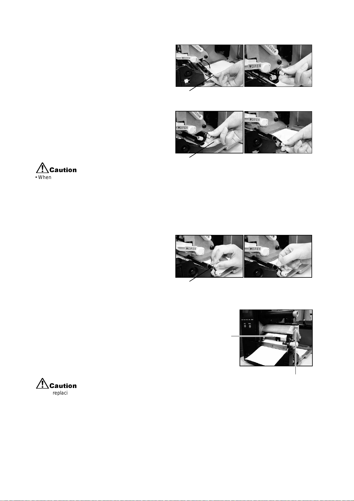
2.3.3 Loading Fanfold Paper under the printer
Section 2: Installation
1. Lift up the main cover. Make sure that th e cover r est s
firmly on th e t op of the printer s o that it will not fa ll
forwa rd and injure yo ur hands.
Note:
It is assumed that the printer is supported on stands to
allow fanfold paper to be loaded fro m beneath the
printer.
2. Release the purple head release lever by pus hing it
downw ards. The print head assembly w ill be lifted up
to allow la bel loading later.
3. Unscrew the fanfold cover and remove
it. Keep the cover and the screw in a
safe place for future use.
anfold
over
crew
Front Cover
Print h ead
Head
release lever
(purple)
4. Loa d the s tack of f anfol d pa per st raig ht
through t he fanfold loa ding slot.
5. Pass the paper through t he fanfold
loading slot and pull it into the c hassis
near the print head assem bly.
Fanfold cover Fanfold loading slo
Fanfold paper
before loading
Pull the paper
into the chassis
Fanfold paper
loaded into slot
Paper is now ready t
load under print hea
GT Series Operator’s Manual Page 2-19
Page 32
SECTION 2: INSTALLATION
P
H
6. Pull up the Label Damper by the
purple knob in a count erc lockwise
directio n until it locks int o place
vertically. If it is already in a vertical
position proceed to th e next step.
7. Pass the paper under the label
guide an d paper senso r. Pull the
label damper knob, a nd the label
damper will drop down to press
against the paper.
Caution
• When replacing paper, bear in mind that the
print head and its surrounding area remain hot.
Keep your fingers away from these areas to
prevent injury.
• Avoid touching even the edge of the print head
with your bare hands.
8. Loosen the label guide knob, and
adjust the s lide guide so th at it
lightly touc hes the edge of th e
paper. Now fasten the label guide
knob tightly.
Label Guide Knob
Label Guide
Label Damper
Label Damper
Label Guide Knob
9. Remount the print head by pushing down on the head lock
lever. The print head sh ould lock into place firmly.
10. If desired, close the main cover and do a test print to
check th at th e label roll has been loaded properly. B e
rint
ead
careful not to get your fingers caught at the bottom ledge
when yo u are closing the main cov er.
Head lo ck
Caution
• When replacing paper, bear in mind that the print head and its surrounding
area remain hot. Keep your fingers away from these areas to prevent injury.
lever
Page 2-20 GT Series Operator’s Manual
Page 33

Section 2: Installation
P
2.3 LOADING LABELS AND TAGS (CONT’D)
2.3.4 Adj ustin g the pa pe r Senso r
Adjustment of the paper sensor is us ually not neces s ary, but the procedure is des c ribed here.
1. Lift up the main cover. Make sure that th e cover r est s
firmly on the top of the printer so that it will not fall
Front Cover
forwar d and injure your hands.
2. The purp le sensor unit is loc ated just abov e the label
damper as s em bly. Slide it out w ards to adjus t it s
position.
aper se n so r
3. You can continue to load media by following the steps
in previous sections, or close the front cover.
Caution
• When closing the front cover, be careful not to injure your fingers due to a sudden release of the heavy cover.
GT Series Operator’s Manual Page 2-21
Page 34

SECTION 2: INSTALLATION
2.4 REPLACING THE PRINT HEAD
Before at t em pting to repla c e t he print head, it is adv isable to con t ac t yo ur local dealer or s ervice
center so that they can assist you in case of problems.
1. Make sure the printer has been turned off for at least 30 minutes so that the print head is not
hot. Lift up the main cover.
2. Push the purple slide lever outwards, in the direction shown
here. Th e print head wil l be released .
Caution
• Do not touch the print head’s heating elements. If you do so inadvertently, use the
cleaning pen (supplied) to clean the area thoroughly. For more details, see Section
4, Cleaning and Maintenance.
4. Pull the print head outwards and disconnect the two connectors
attached to it.
5. Attac h t he connectors t o t he new print head.
6. Ther e ar e tw o hoo ks on th e l ef t an d ri gh t si de s of t he p ri nt hea d.
Insert the left-side hook into the printer first. Mount the hook
under the c y linder marked w it h t he arrow sym bol.
7. Now mount the right-side hook of the print head under the
cylinder ma rk ed with the arrow symbo l. Th e print head
should sn ap into place firm ly. If not, release the prin t h ead and
try ag ain from St ep 6 above .
Page 2-22 GT Series Operator’s Manual
Page 35

2.5 TURNING THE PRINTER ON/OFF
1. After rem ov ing the cable co v er at t he rear of the prin t er
(See Pag e 2-7), you can proceed to install the inte rf ac e and
power cables as shown.
2. To limit mov ement of the ca bles, you can optionally ch annel
the cables t hrough the cable hook area at the base of the
printer.
Section 2: Installation
3. Insert the power cable fir s t to t he printer, th en connect th e
other end to the power outlet. If necessary, use an adapter to
match the prongs on the power cable to the sockets in the
AC outl et.
Caution
• Always use a grounded power cable to protect against electrical leakage and
electrical shocks.
4. To turn the printer ON, press the power switch to the “I” side.
When the printer is succes s f ully turned on, the LCD sc reen
will display something similar to that shown here.
Caution
• To prevent electric shocks, make sure your hands are dry when you operate the
power switch, or when you pull out or insert power cables and switches.
5. If the printer does not respond, refer to the Troubleshooting
section of this manu al.
6. Before turning the print er off, perform the follow ing steps:
Take the pri nt er off lin e by pre ssi n g th e Lin e bu tto n. The LC D
shows the following:
• Press the Feed button to eject any label at the front of the
printer.
• Lightly pu ll th e paper diagonally dow nw ard to tear off the
label.
7. To turn the pr inter of f, press the pow er swit c h to the “O” sid e.
GT Series Operator’s Manual Page 2-23
Page 36

SECTION 2: INSTALLATION
This pag e is intentional ly lef t b lank
Page 2-24 GT Series Operator’s Manual
Page 37
Section 3: Configuration and Operation
Test prints can be performed.
3
CONFIGURATION AND OPERATION
Before using the printer, it is best to read this manual thoroughly first. Otherwise, you may disturb
default set t ings around w hic h t he instructional procedures in this manual are bas ed upon.
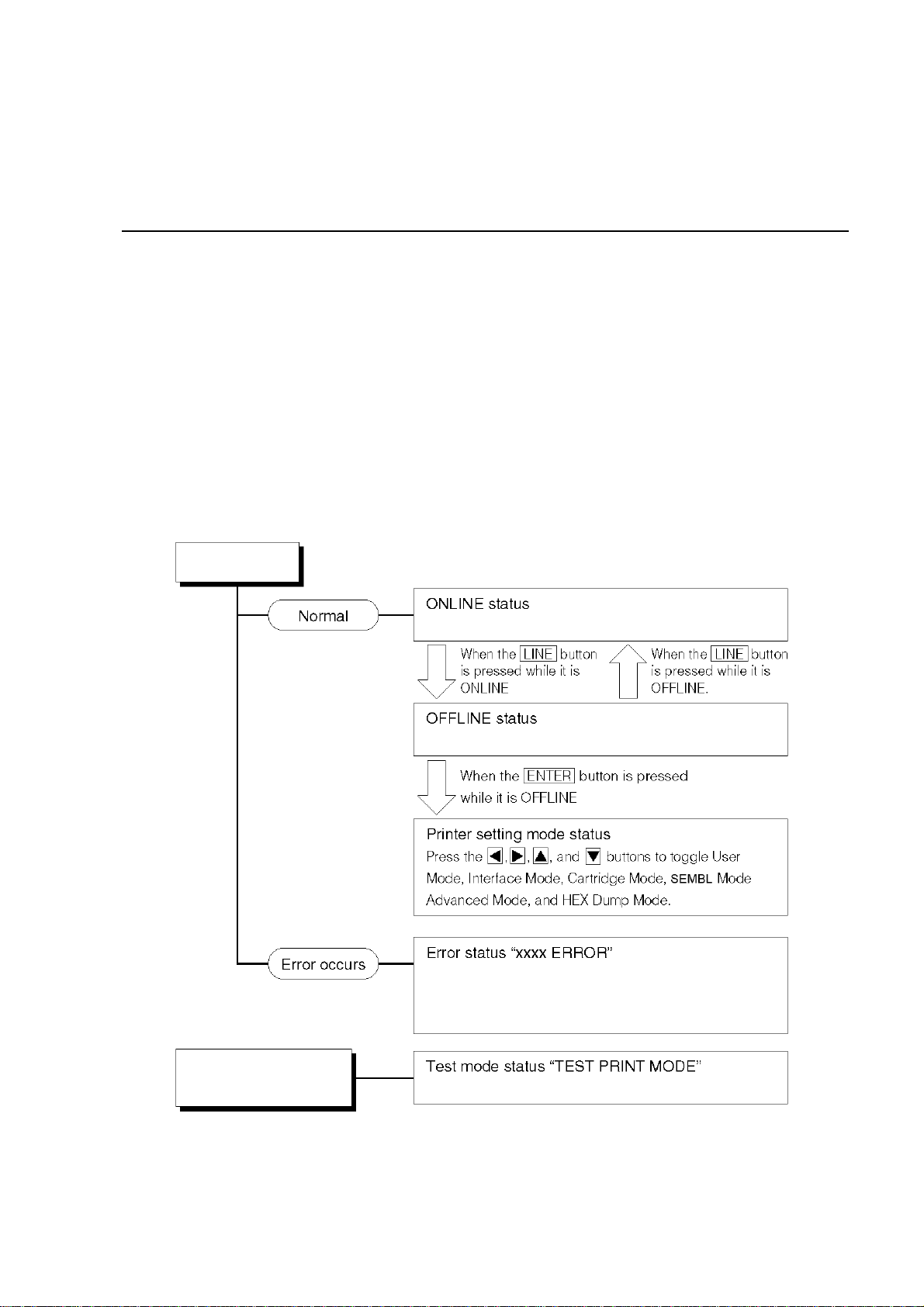
3.1 OPERATING MODES
The operat ing status of th is printer can be s et t o one of five mod es :
1) Online mode
2) Offline mode
3) Printer Set t ing modes:
User Mode, Interface Mode, Cartridge Mode, SEMBL Mode, Advanced Mode, Hex
Dump Mode, Test Print Mode)
4) Error mode
5) Test Print mode
Turn printer on
The printer status is normal; printing can begin
Printing is stopped; ready for configuration
Printer has not been set up correctly. The LCD
shows “H ead Open”, “Paper End”, et c
Hold down Feed key
and turn printer on
GT Series Operator’s Manual Page 3-1
Page 38

Section 3: Configuration and Operation
O
3.2 THE OPERATION PANEL
Overview of the Operation Panel
Status Icon display area
Up to five icons can appe ar here to
indicate the current printer status.
The same area can also display two
lines of alphanumeric text instead.
Two-line M essage di sp l ay area
Other icon s , o r up t o t w o lines of
alphanumeric messages, can be
displayed here.
In total, up to four lines of text can be
displayed on the whole sc r een.
How To Adjust Screen Contrast
In ONLINE or SEMBL mode, press the left/right arrow
buttons repeatedly to adjust the contrast.
Contrast settings are reset whenever you reset the
printer to default settings.
vervie w o f th e Display for Pr i n ter Setting
Description of Setting
The curr ent function b eing set can b e
described in up to two lines of text.
Value to be Set
Available setting va lues or options are
displayed here in up to two lines.
Usable Navigation Buttons
Shows only t hose arrow k ey s t hat are
valid for ch anging the cur rent setting.
The arrow k ey s are a combination of
Page 3-2 GT Series Operator’s Manual
Page 39

3.3 SCREEN ICONS AND THEIR MEANING
Section 3: Configuration and Operation
GT Series Operator’s Manual Page 3-3
Page 40

Section 3: Configuration and Operation
3.3 SCREEN ICONS AND THEIR MEANING (CONT’D)
Page 3-4 GT Series Operator’s Manual
Page 41

Section 3: Configuration and Operation
3.4 ONLINE AND OFFLINE MODES
3.4.1 Online Mode
Pressing the LINE button causes the printer to go ONLINE or
OFFLINE alternately.
When the printer is ONLINE, the following activities will be possible:
• The printer is ready to receive print data from the computer or
other connected devices
• The printer is ready to start printing
3.4.2 Offline Mode
When the printer is ONLINE, pressing the LINE button once will
cause the printer to go OFFLINE.
When the printer is OFFLINE, the activities for ONLINE mode are
no longer p os s ible, but the fol low ing activities will be poss ible:
• The printer can eject labels when you press the FE ED button.
• The printer can be switched to other modes when you press th e
ENTER button.
• Any printing job can be sto pped once the printer is broug ht
OFFLINE
• Any printing job can be ca nc elled once th e CANCE L button is
pressed in OFFLINE mode. The menu for canceling the print job
then appears.
• Received data that is stored in the buf fe r m em ory can be s av ed
into a memory cartridge, if the LINE button is pressed and held
down for at least five seconds in OFFLINE mode. The following
screens will appear.
GT Series Operator’s Manual Page 3-5
Page 42

Section 3: Configuration and Operation
3.5 USER MODE
The follo w ing settings a re av ailable in U s er M ode:
• OFFSET VOLUME (volume of the built-in buzzer/speaker)
• PRINT SPEED (print s peed settin g)
• PRINT DARKNESS (print density setting)
• PRINT OFFSET (print position correction setting)
• ZERO SLASH (zero sl as h c hangeov er s et t ing)
• JIS CODE (JIS code c hangeover se t ti ng)
• KANJI FONT (Kanji fon t ch angeover se tting)
• CHARACTER PITCH (proportional pitch setting)
3.5.1 Entering User Mode
1. Press the LINE button to take the printer OFFLINE.
2. Pull dow n t he cover of the Operation P anel and press ENTER.
The ONL I N E M OD E sc reen ap pears.
3. Press the arrow buttons until you see “USER
MODE”, then press ENTER.
Note:
The bottom right-hand corner of th e s c reen somet im es displays
one to four a rrow symbols (s ee circled s ymbols on the ri ght).
Each arrow s y m bol represe nt s th e c orresponding arrow bu tton
on the operation panel which is valid for the changing the current
screen or its se t ti ngs .
4. When the first User Mo de screen ap pears, you will need the
yellow scre w driver (fastened to the O peration Panel flap), to
adjust the OF F SET VOL U M E, PI T C H , OF F SET and
DARKNESS potentiometers. See Sectio n 3. 5. 2 Setting Pri n t
Speed.
5. Subsequently, pressing the ENTER button brings you to screens
for setting PRINT SPEED, PRINT DARKNESS and OFFSET. At
any time, pr es s ing CANCEL takes you back one screen.
Pressing the FUNCTION button returns you immediately to the
main User Mode screen.
Page 3-6 GT Series Operator’s Manual
Page 43

Section 3: Configuration and Operation
3.5.2 Setting Buzzer Volume, Print Pitch, Print Offset, Print Darkness
The volume level of the built-in speaker buzzer can be adjusted at
the first menu of the User Mode. Use th e y ellow screwd riv er to
adjust the VOLUME po tentiometer below the L C D. The value on
the screen changes as you turn the screwdriver clockwise or
counter-clockwise.
Next, you c an use the scre w driver to rota te th e potentiomet er for
the Print Pitch. This setting adjusts where printing begins
vertically , re lat iv e to the bottom edge (nearest the print head) of
each label. Th e m ax imum val ue allow ed is 3.75 mm.
Adjusting th e OFFSET potentiometer adjusts the tear-off stop
position for use with a cut t er, peeler.
Finally, adjusting the Print Darkness potentiometer adjusts the
pri nt darkne s s .
Print hea d
When all the set tin gs are satisfactor y , pre s s the ENTER button to
proceed to set other parameters in the User Mode.
3.5.2 Setting Print Speed
After setting OFFSET VOLUME, PITCH, OFFSET and
DARKNESS, pressing ENTER takes you to the Print Speed setting.
This setting can be used to achieve a high print speed that does not
compromise print qua lit y .
Press the buttons to change the setting. Press the ENTER
button to co nf irm a setting a nd proceed to the next scree n.
If quality printing cannot be obtained due to the quality of the paper
or the printing contents, lower the speed accordingly. On the GT408
and GT412, the print speed can be set in 11 steps. On the GT424,
the print speed can be se t in fiv e steps in GT4 24. The table below
shows the fa c to ry def ault print speed for diffe rent print resolutions.
ref point 0,0
direction of label motion
Print offse t
Print head resolution:
default print speed setting
203 dpi: default 06 inches/sec 02, 03, 04, 05, 06, 07, 08, 09, 10, 11, 12 inches/sec
305 dpi: default 06 inches/sec 02, 03, 04, 05, 06, 07, 08, 09, 10, 11, 12 inches/sec
609 dpi: default 03 inches/sec 02, 03, 04, 05, 06 inches/sec
GT Series Operator’s Manual Page 3-7
Available print speed settings (lower numbers mean
slower print speeds)
Page 44

Section 3: Configuration and Operation
-
3.5.3 Setting Print Darkness
After se tti ng Pri nt Sp eed, the ne xt s cr een a l low s yo u to set t he Pr i nt
Darkne s s —t he darknes s o f the print on pa per.
This setting can be set from 1 (lightest) to 5 (darkest). The default
setting is 3.
Press the / butto ns to ch ange the sett ing. Press the ENTER
button to c onfirm a setting and proc eed to the next screen.
3.5.4 Setting Print Offset
After setting Print Darkness, the next screen allows you to set the
Print Pos it ion Offset— w hic h refers to the vertical and horizontal
shifting of the entire print area, relative to the start position of
printing (V=0, H=0) , define d by defaul t t o be the bott om righ t hand
corner of th e label.
Use the / buttons to select the V or H setting, and the /
buttons to change a highlighted setting. Press the ENTER
button to c onfirm a setting and proc eed to the next screen.
The V setting is for the Vertical print offset. A positive (+) offset
means the printing is shifted towards the print head; a negative (-)
offset means shifting away from the print head. If the Print Pitch
setting has been used to offset the vertical start position, then all
Vertical offset adjustments are made relative to that start position.
The H set ti ng is f or t he Horizontal print offset . Th e + or - prefix
determines whether the offset is to the left or to the right of the
reference point.
Printer Valid H and V settings (in dots)
GT408 V: +/- 000 to 1424 dots, H: +/- 000 to 832 dots
GT412 V: +/- 000 to 2136 dots, H: +/- 000 to 1248 dots
GT424 V: +/- 000 to 4272 dots, H: +/- 000 to 2496 dots
After setting the Vertical and Horizontal OFFSET, press ENTER
to proceed to the next setting.
directio n of label motion
Print hea d
H+V-H
ref point 0,0
V+
Print offset
Page 3-8 GT Series Operator’s Manual
Page 45

Section 3: Configuration and Operation
3.5.5 Setting Zero Slash Changeover
You can use this setting to determine whether zeroes are printed
with a slash across them or not. The zero slash (excluding Kanji)
can be set to either "0" or "Ø".
Use the / buttons to select YES or NO. ‘YES’ means zeroes
will be print ed w it h a diagonal sla sh across th em . ‘N O’ means
otherwise. The default v alue is ‘NO’.
Press ENTER to select the desired option and proceed to the next
setting.
3.5.6 Setting JIS Kanji Code Changeover*
* option is only valid for printing in Japanese
The printer can be set to use either JIS code or Shift JIS code.
Use the / buttons to select JIS or SJIS. The default value is
JIS code.
Press ENTER to confirm your selection and proceed to the next
setting.
3.5.7 Setting Kanji Font Style*
* option is only valid for printing in Japanese
The Kanji font style can be set to either “GOTHIC” or “MINCHO”.
Use the / buttons to select GOTHIC or MINCHO. The defaul t
value is GO T H I C .
Press ENTER to confirm your selection and proceed to the next
setting.
GT Series Operator’s Manual Page 3-9
Page 46

Section 3: Configuration and Operation
3.5.7 Setting Proportional Pitch
This set tin g determine s whether the s pace surrou nding each te xt
character is of a fixed width, or whether that space is to be varied to
be visually more pleasant.
Use the button s t o se lec t e it her PROPO RT IONA L o r FIX ED.
The defa ult value is FIXED.
Press ENTER to confirm your selection and return to the main User
Mode screen. Pr ess the FUNCTION or CANCEL key to exit the User Mode setting.
Note:
The sub jec t fo nt s are from x21 to x24
Page 3-10 GT Series Operator’s Manual
Page 47

Section 3: Configuration and Operation
3.6 INTERFACE MODE
In this mode, you can set various parameters governing the use of interface cards. Due to the
wide range of interface card s av ailab l e, only th e defaul t inter f ace configurat ion settings are
covered in th is se c ti on. A flowchart overview of adv anced setti ngs for all the op t ional interface
cards is inc luded at the end of th is ch apter, and a detailed discussion of adv anced set tin gs c an
be found in t he GT Series S erv ic e Manual a v ailable upon re quest.
3.6.1 Entering Interface Mode
1. Press the LINE button to take the printer OFFLINE.
2. Pull down the co v er of the Operati on Panel and pre s s ENTER.
The ONL INE MODE s c reen appears.
3. Press the arrow buttons until you see
“INTERFACE MODE”, then press ENTER to perform the first
setting. At any time within this mode, pressing CANCEL takes
you back one screen. Pressing the FUNCTION b utton returns
you immediat ely to th e ma in Interface Mo de screen.
3.6.2 Enabling Interface Card Configuration
The first setting in the Interface Mode lets you select whether you
wish to configure an interface card for bi-directional communication.
If YES is selected, the next screen lets you select an interfa ce card
to configure.
If NO is selected, the next screen lets you choose the correct port
for receiving print data . Se e Section 3.6.4 Selecting The Data
Input Port.
Press the / buttons to select either YES or NO.
Press the ENTER butto n t o c onfir m the sett ing and proceed t o t he
next scree n (s ee either Section 3.6.3 or 3.6.4 on page 3-12).
GT Series Operator’s Manual Pa ge 3-11
Page 48

Section 3: Configuration and Operation
3.6.3 Assigning An Interface Card For Printing
This set tin g lets you select w hic h installed in t erf ac e card is to be
used for bi-directional communication/printing. The other card is
then presumed to be a mini LAN card, which is intended for
transmitting printer status information to a LAN.
The card se lected by def ault for bidirec t ional communication is th e
one that is not a mini LAN card. Card2 is assumed to be a mini LAN card.
Press the / buttons to select either CARD1 or CARD2.
Press the ENTER button to con f irm a s et t ing and proceed to the nex t screen.
3.6.4 Selecting The Data Input Port
Use this setting to define which installed interface card is to be used
as the por t f or rece iv ing print data. The def ault value is CAR D 1
(which is the non mini LAN card).
Press the / buttons to select either CARD1 or CARD2.
Press the ENTER button to con f irm a s et t ing and proceed to the
next screen.
Note:
If you set th e data input po rt to be C ARD2 but print data is received at CAR D 1, printing will not
occur. The reverse also holds true.
3.6.5 Enabling or Disabling The Status Return Port
Use this s etting to enable or disabl e the status ret urn port .
The inte rf ac e c ard which is not being used as th e data input po rt
(see Section 3.6.4 above) is the status ret urn port. The def ault
value is ENABLE.
Press the / buttons to select either ENABLE or DISABLE.
Press the ENTER button to con fi r m a sett ing an d ret urn to t he ma in s cr een of th e Int er fa ce Mod e.
Page 3-12 GT Series Operator’s Manual
Page 49

Section 3: Configuration and Operation
3.7 CARTRIDGE MODE
In this mod e y ou c an manage t he optional me m ory cartridge t hat can be ins t alled to provid e
increased storage capacity for text and graphics.
3.7.1 Entering Cartridge Mode
1. Press the LINE button to take the printer OFFLINE.
2. Pull down the co v er of the Operati on Panel and pre s s ENTER.
The ONL INE MODE s c reen appears.
3. Press the arrow buttons until you see
“CARTRIDGE MODE”, then press ENTER to perform the first
setting. At any time within this mode, pressing CANCEL takes
you back one screen. Pressing the FUNCTION b utton returns
you immediately to the main Cartridge Mode screen.
3.7.2 Cartridge Formatting Option
Use this func t ion to clear the m emory car tr idge of all contents.
Press the / buttons to select either YES or NO.
Selecting N O returns you to th e m ain Cartridge Mode screen.
Selecting YES causes the FORMAT START screen to appear (see
the next se ction).
Press the ENTER butto n t o c onfir m the sett ing and pr oceed to t he
next scree n.
3.7.3 Start Cartridge Formatting
If you selected YES at CARTRIDGE FORMAT screen, this screen
lets you start or cancel the c art ridge initia liz at ion procedure.
Press the / buttons to select either YES or NO.
Selecting NO returns you to the CARTRIDGE FORMAT screen.
Selecting YES begins th e c art ridge initia liz ation (see page 3-14)
Press the ENTER butto n t o c onfir m the sett ing and pr oceed to t he
next scree n.
GT Series Operator’s Manual Pa ge 3-13
Page 50

Section 3: Configuration and Operation
3.7.4 Cartridge Formatting Progress
If you sele c t ed YES at the FOR MAT STA R T screen, this nex t
scree n lets you mo nitor th e progres s of t he formatting.
When formatting is complete, the next screen appears.
Press the ENTER button to return to the main CARTRIDGE MODE
screen.
Page 3-14 GT Series Operator’s Manual
Page 51

Section 3: Configuration and Operation
3.8 SEMBL MODE
SEMBL stands for SATO EMbedded BASIC Language. This feature allows software programs
written in standard BAS I C language to be loaded into th e printer and ex ec uted with out any
further connection to a c om puter. Fo r m ore details cons ult a qualified SATO sales person.
In this mod e y ou c an control the operatio n of BASIC progr am s loaded into m em ory.
3.8.1 Entering SEMBL Mode
1. Press the LINE button to take the printer OFFLINE.
2. Pull down the co v er of the Operati on Panel and pre s s ENTER.
The ONL INE MODE s c reen appears.
3. Press the arrow buttons until you see “SEMBL
MODE”, then press ENTER to perform the first setting. At any
time within this mode, pressing CANCEL takes you back one
screen. Pressing the FUNCTION butto n retu rns you immedi ate ly
to the main SEMBL Mo de screen.
3.8.2 Selecting The Start Program
This first se tting in SEMBL M ODE allows y ou to specify w hic h
software program in the p rinter’s memory will be exec uted when
SEMBL Mode is started.
Use the buttons to select either NONE or to select from a list
of BASIC programs alr eady loaded in m emory.
Press ENTER to confirm your selection and proceed to the next
setting. Pr es s th e FUNCTION or CANCEL key to exit the SEMBL
Mode setting.
Name of program in memory
GT Series Operator’s Manual Pa ge 3-15
Page 52

Section 3: Configuration and Operation
3.8.3 The SEMBL Status Screen
This screen indicates the number of labels that remain to be
processed by the program.
Press ENTER to return to the main SEMBL Mode screen.
Page 3-16 GT Series Operator’s Manual
Page 53

Section 3: Configuration and Operation
3.9 ADVANCED MODE
Advance d M ode lets you c onf igure the more advanc ed f eatures of the printer hardw are.
3.9.1 Entering Advanced Mode
1. Press the LINE button to take the printer OFFLINE.
2. Pull down the c ov er of the Opera tio n Panel and press
ENTER. The ONLIN E M OD E s c reen appears.
3. Pres s the arrow butto ns unti l you s ee “ADV ANCED
MODE”, then press ENTER to perform the first setting. At any t im e
in this mode, y ou can press th e FUNCTION or CANCEL key to
return to the Advanced Mode screen.
3.9.2 Selecting The Print Density
This first setting in ADVANCED MODE lets you set how dark the
print qualit y is. Av ailable options are from ‘A’ to ‘F’, with ‘F’ being
the darkest density. The default val ue is ‘A’.
Adjustment of this setting is usually unnecessary . T o adjust the
print density, use the / buttons to select an option.
Press ENTER to confirm your selection and proceed to the next
setting.
3.9.3 Setting the Automatic Detection of Optional Units
The next setting, PRINTER TYPE AUTO SETTING, determines
whether the printer automatically detects the installation of optional
peripher als s uc h as a peeler or c ut t er. If detected, an optional
peripher al w ill be used without needin g f urther user configuration.
Use the / buttons to select either YES or NO. The default
option is YES (auto detect). Choose NO if optional devices are
installed, but you have wish to override the automatic settings.
Press ENTER to proceed to the next setting.
GT Series Operator’s Manual Pa ge 3-17
Page 54

Section 3: Configuration and Operation
3.9.4 Choosing Continuous or Tear Off Operation
With this setting, you can choose between continuous paper feed or
Tear Off operation. If a cutter or peeler has been installed correctly,
you will al s o s ee t he DISPENSER and CU T T ER settings. If th e
printer s upports linerl es s labels, you will also see a LIN ERLESS
option.
Press the bu t to ns t o s elect any one of th e options. The
default setting is CONTINUOUS.
Press the ENTER button to con f irm t he setting and proceed to t he
next screen.
3.9.5 Backfeed Operation Settings
The print er can be set to a pply or not appl y a bac k f eed to the label
before or after printing each label.
Press the buttons to choose from AFTER, BEFORE or
NONE. The default setting is AFTER.
Press the ENTER button to con f irm t he setting and proceed to t he
next screen.
3.9.6 Configuring the Internal Winding Unit
The print er can be set to a pply or not appl y a bac k f eed to the label
before or after printing each label.
Press the / buttons to choose from AFTER, BEFORE or
NONE. The default setting is AFTER.
Press the ENTER button to con f irm t he setting and proceed to t he
next screen.
Page 3-18 GT Series Operator’s Manual
Page 55

Section 3: Configuration and Operation
3.9.7 Setting the Print Mode
The printe r c an be switched to operate in The r m al Transfer or
Direct Thermal mode with this setting.
Press the / buttons to select the TRANSFER or DIRECT
option. The default value is TRANSFER.
Press the ENTER butto n t o c onfir m the sett ing and pr oceed to t he
next scree n.
3.9.8 Configuring the Paper Sensor
The printe r c an be switched to operate in The r m al Transfer or
Direct Thermal mode with this setting.
Press the / buttons to select the TRANSFER or DIRECT
option. The default value is TRANSFER.
Press the ENTER butto n t o c onfir m the sett ing and pr oceed to t he
next scree n.
3.9.9 Configuring the Paper Sensor Type
This setting specifies which pape r s ensor is to be use d: Gap
sensor (penetration sensor) and I-Mark sensor.
Press the / buttons to select between I-Mark or GAP
settings. The default value is I-MARK.
Press the ENTER button to confirm the setting and proceed to the
next scree n.
GT Series Operator’s Manual Pa ge 3-19
Page 56

Section 3: Configuration and Operation
3.9.10 Turning Head Check Function ON/OFF
The print er can be set to p erf orm a check of the print head when
printing each label.
Press the / buttons to select the ENABLE or DISABLE option.
The defa ult value is ENA BLE.
Press the ENTER button to con f irm t he setting and proceed to t he
next screen.
3.9.11 Choosing the Type of Head Check
If Head C heck has been enabled, yo u w ill s ee this scree n.
Here, you can specify the print head checking to be performed
unconditionally, or only when barcodes are being printed.
Press the / buttons to select the NORMAL or BARCODE
option. The default option is NORMAL.
Press the ENTER button to con f irm t he setting and proceed to t he
next screen.
About the Head Check function
• The head check function detects the integrity of the heating elements in the thermal
print head. However, malfunctions cannot be detecte d ins t antaneous ly —a few
printed labels may start s howing prin t ing defects be fo re t he printer war ns of a print
head error.
• After detection of a print head error, us e a s c anner to check all affected labels.
• When a head check error occurs during normal printing (barcodes, text and graph-
ics), pres s a nd hold down th e FE ED button for five seconds. At the next screen,
select NORMAL and then press and hold down the LINE and FEED buttons for five
seconds to cause printing to resume. If the head check error occurs again, set the
type of head check to BA R C ODE and see if printing can be resumed normally .
• Although restricting the head check type to BARCODE allows you to continue print-
ing, you should only do s o in order to complete an ur gent print job. C heck the
printed labels to make su re the output is us able in spite of th e head error. As s oon
as possible, stop usin g th e print head to prev ent further damage. If necessary, get
the print head replaced.
Page 3-20 GT Series Operator’s Manual
Page 57
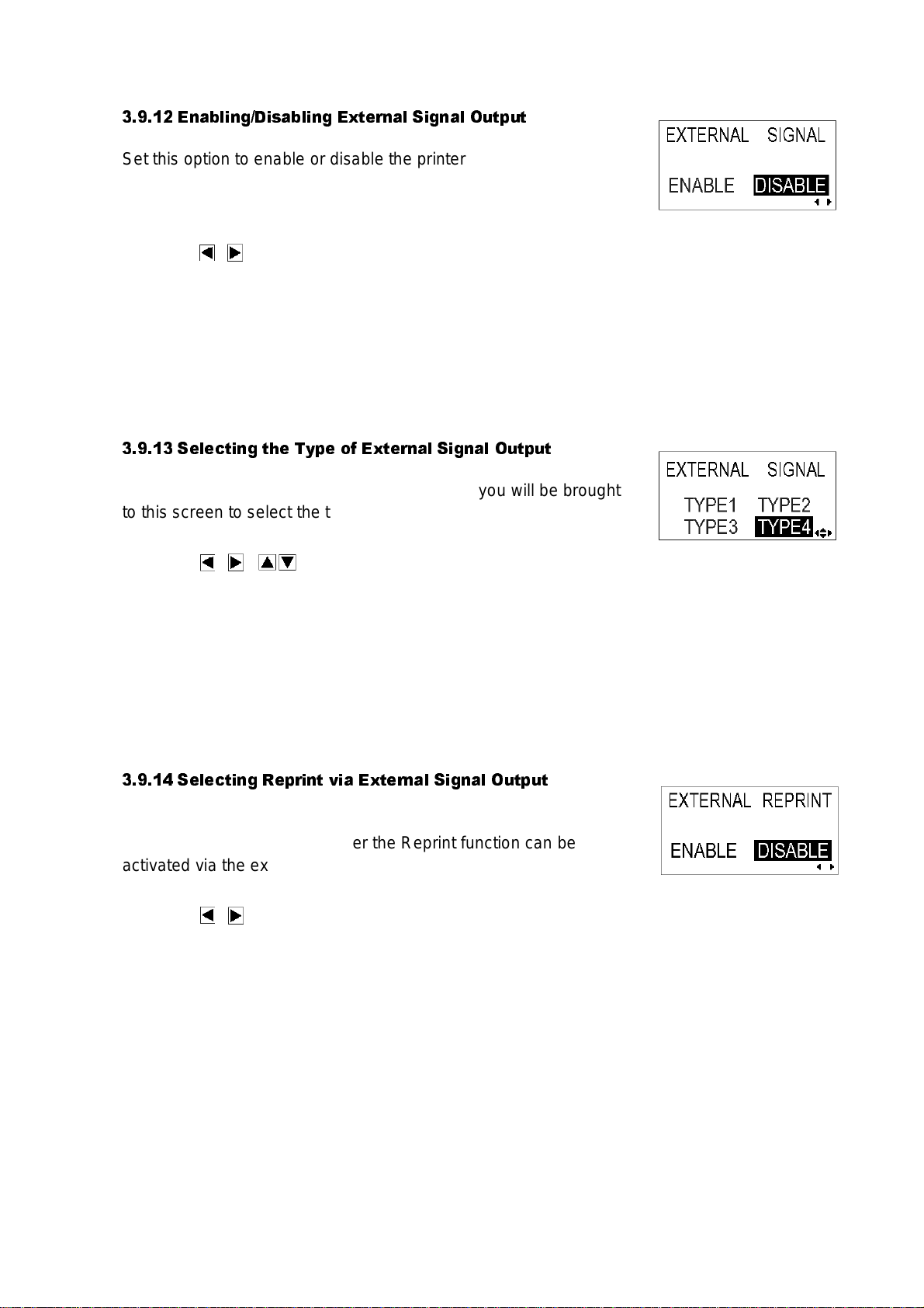
Section 3: Configuration and Operation
3.9.12 Enabling/Disabling External Signal Output
Set this opt ion to enable or disable the printer’s ext ernal signal
communic ation port. If th e port is enabled, you can s end and
receive data using an appropriate device plugged into the EXT port.
Press the / buttons t o sele ct the ENABLE or DIS ABLE opti on.
The def ault value is DI SABLE.
Press the ENTER butto n t o c onfir m the sett ing and pr oceed to t he
next scree n.
3.9.13 Selecting the Type of External Signal Output
If the External Signal Ou t put option is enabled, you will be brought
to this screen to select the type of PREND output signal.
Press the / buttons to select TYPE1, TYPE2, TYPE3
or TYPE4. The default value is TYPE4. For more details, refer to
the SBPL Programming Guide found in the accessory CD -R OM.
Press the ENTER butto n t o c onfir m the sett ing and pr oceed to t he
next scree n.
3.9.14 Selecting Reprint via External Signal Output
If the External Signal Ou t put option is enabled, you will be brought
to th i s scre e n to choose whether the Repr i nt functio n can b e
activated vi a t he external s ignal port.
Press t he / butto ns t o select EN ABLE or DISABLE. Th e
default set t ing is DISAB LE.
Press the ENTER butto n t o c onfir m the sett ing and pr oceed to t he
next scree n.
GT Series Operator’s Manual Pa ge 3-21
Page 58

Section 3: Configuration and Operation
3.9.15 Using the Auto Online Feature
The printer can be set to go into ONLINE mode automatically upon
being turned on. Other w is e, th e printer sta rt s in th e OF F LINE state.
Press the / buttons to select YES or NO. The defaul t settin g is
YES.
Press the ENTER butto n t o c onfir m the sett ing and pr oceed to t he
next scree n.
3.9.16 Enabling Auto Feed
The printe r c an be set to feed one label upon being turned on.
Press the / buttons to select YES or NO. The defaul t settin g is
NO.
Press the ENTER butto n t o c onfir m the sett ing and pr oceed to t he
next scree n.
3.9.17 Enabling Auto Feed On Error
The printer can be set to feed one label upon going into ONLINE
state after an error has been corrected.
Press the / buttons to select YES or NO. The defaul t settin g is
NO.
Press the ENTER butto n t o c onfir m the sett ing and pr oceed to t he
next scree n.
GT Series Operator’s Manual Pa ge 3-22
Page 59

Section 3: Configuration and Operation
3.9.18 Specifying the Protocol Code Format
The ESC sequence in SBPL commands can be defined as
standard (using non-printable code 1BH) or non-standard (some
other user co de).
Press the / buttons to select the STANDARD or NONSTANDAR D option. Th e default setting is STANDARD.
Press the ENTER butto n t o c onfir m the sett ing and pr oceed to t he
next scree n.
3.9.19 Specifying The SEMBL Start Mode
The printer can be set to go into SEMBL Mode automatically (to
execute a preloaded B ASIC program) upon being turned on.
Press the / buttons to select YES or NO. The defaul t settin g is
NO.
Press the ENTER butto n t o c onfir m the sett ing and pr oceed to t he
last menu s c reen of the AD VANCED MO D E settings.
3.9.20 Specifying The SEMBL Auto Start Program
If the printer has been set to go into SEMBL Mode automatically
upon being turned on, this setting will be available to let you specify
the program t o be automati c ally execute d.
Press the buttons to select from a list of valid programs
preloade d into memory . O r s elect the default NONE opt ion, in
which case no program will be automatically executed.
Press the ENTER button to return to the first ADVANCED MODE
screen.
GT Series Operator’s Manual Pa ge 3-23
Page 60

Section 3: Configuration and Operation
3.10 HEX DUMP MODE
3.10.1 Entering HEX Dump Mode
1. Press the LINE button to take the printer OFFLINE.
2. Pull dow n t he cover of the Operation P anel and press ENTER.
The ONL I N E M OD E sc reen ap pears.
3. Pres s the arrow butt on s un ti l yo u se e “HE X DU MP
MODE”, then press ENTER to perform the first setting. At any
time within this mode, pressing CANCEL takes you back one
screen. Pressing the FUNCTION button returns you immediately
to the main Hex Dump screen.
3.10.2 Selecting Data To Dump
Here yo u c an c hoose to dump either incoming data (rec eive data)
or print dat a already stored in the buffer (receive buffer) .
Press the buttons to choose RECEIVE DATA or RECEIVE
BUFFER. Note that RECEIVE BUFFER cannot be selected when
there is no received data.
Press the ENTER button to con f irm t he setting and proceed to t he
next screen.
3.10.3 Controlling the Hex Dump Mode
During t he H EX Dump, th e f ollowing scr een appears. T he number
of labels printed will be shown. Whe n printing is do ne, press the
LINE button to take the printer OFFLINE. The press ENTER to
return to the main HEX DUMP Mode screen.
If you dumping the RECEIVE BUFFER, take the printer OFFLINE to
stop any inc oming data fr om af f ec t ing the buffer. O nly th en can the
buffere d data be printe d. T he printer goes ON LINE aut om atically
after the printing.
Page 3-24 GT Series Operator’s Manual
Page 61

Section 3: Configuration and Operation
3.11 TEST PRINT MODE
3.11.1 Entering Test Print Mode
1. Make sure the printer is turned OFF.
2. Press and hold down th e FEED button while turning the printer
ON. The dis play will show T EST PRINT M OD E.
3. Press the buttons to choose from six options, as
explained in the next sub-section.
At any time within this mode, pressing CANCEL takes you back
one scree n. Pressing th e FUNCTION button returns you
immediately to the main Test Print screen.
3.11.1 Choosing What The Test Print Contains
The six settings in this mode are as follows:
Press the buttons to choose any option to set the test print contents.
Press the ENTER button to conf irm the setti ng and proceed to the next s c reen.
GT Series Operator’s Manual Pa ge 3-25
Page 62

Section 3: Configuration and Operation
3.11.2 Setting Test Print Width for Configuration, Barcode
and Head Check
If you cho s e t es t prints of Configuration, Barcode and H ead Check
in the prev ious menu, th is screen lets y ou c hoose the widt h of the
test print from “04” to “10” cm, in increments of 1 cm,
Press the buttons to choose the print size. Press the
ENTER button to confirm t he s et t ing and proc eed to the next
screen.
3.11.3 Setting the Size of the Factory Test Print
For Fact ory t es t prints, this screen appears instead of the previous
screen for setting print size. In this screen, you can choose only to
print the test results in LARGE or SMALL print widths. The LARGE
setting results in a 10 cm print width. The SMALL setting results in a
4 cm print width.
Caution
If you are using narrow labels, do NOT set this option to LARGE; otherwise, this may damage the print head.
Press the buttons to choose LARGE or SMALL. Press the ENTER button to confirm the
setting and proceed t o t he next screen.
3.11.4 Starting the Test Print
When you are ready to print out the test data, press the ENTER
button. T he test print will s t art , and it will cycle co nt inuously.
During printing, the ENTER button can be used to suspend and
resume the test printing.
To exit the Test Print mode, turn of the printer.
Page 3-26 GT Series Operator’s Manual
Page 63

3.12 OVERVIEW OF ALL MODES
Section 3: Configuration and Operation
GT Series Operator’s Manual Pa ge 3-27
Page 64

Section 3: Configuration and Operation
3.12 OVERVIEW OF ALL MODES (CONT’D)
Page 3-28 GT Series Operator’s Manual
Page 65

3.12 OVERVIEW OF ALL MODES (CONT’D)
Section 3: Configuration and Operation
GT Series Operator’s Manual Pa ge 3-29
Page 66

Section 3: Configuration and Operation
3.12 OVERVIEW OF ALL MODES (CONT’D)
Page 3-30 GT Series Operator’s Manual
Page 67

3.12 OVERVIEW OF ALL MODES (CONT’D)
Section 3: Configuration and Operation
GT Series Operator’s Manual Pa ge 3-31
Page 68

Section 3: Configuration and Operation
3.12 OVERVIEW OF ADVANCED INTERFACE MODE CONFIGURATIONS (CON’TD)
Page 3-32 GT Series Operator’s Manual
Page 69

Section 3: Configuration and Operation
3.12 OVERVIEW OF ADVANCED INTERFACE MODE CONFIGURATIONS (CON’TD)
Chart continued on next page
GT Series Operator’s Manual Pa ge 3-33
Page 70

Section 3: Configuration and Operation
3.12 OVERVIEW OF ADVANCED INTERFACE MODE CONFIGURATIONS (CON’TD)
Page 3-34 GT Series Operator’s Manual
Page 71

Section 3: Configuration and Operation
3.12 OVERVIEW OF ADVANCED INTERFACE MODE CONFIGURATIONS (CON’TD)
Chart continued on next page
GT Series Operator’s Manual Pa ge 3-35
Page 72

Section 3: Configuration and Operation
3.12 OVERVIEW OF ADVANCED INTERFACE MODE CONFIGURATIONS (CON’TD)
Page 3-36 GT Series Operator’s Manual
Page 73

Section 3: Configuration and Operation
3.13 RESTORING FACTORY DEFAULT SETTINGS
The printer is configured with default settings at the factory. During use, some of the default
settings may be changed in a way that causes the printer to act in an undesirable manner.
However, there is special Default Mode in which you can quickly restore all printer settings to the
original fac t ory s et t ings as shown here:
3.13.1 Entering Default Mode
1. Make sure th e printer has be en turned O F F .
2. Hold down the CANCEL button and turn the printer ON. The
followin g D EF AULT MODE display sh ould appear. At any time
with in thi s m ode, pressing CANCEL takes you back one screen.
Pressing the FUNCTION button returns you immediately to the
main Hex Dump screen.
3. Press the arrow buttons to choose between PRINTER
SETTING and ALT. PROTOCOL. The first option resets all
settings to the default , whil e t he ALT. PROTOCOL option rese ts
only the pr ot oc ol code. Pres s t he ENTER button to confirm the
setting and proceed to the next screen.
GT Series Operator’s Manual Pa ge 3-37
Page 74

Section 3: Configuration and Operation
3.13.2 If You Chose to Reset Printer Settings
In the previous menu, if you chose PRINTER SETTINGS, the
followin g s c reen appears.
4. Press the arrow buttons to choose between YES and
NO. If you select NO, you will return to the main DEFAULT
MODE screen.
5. Press ENTER to proceed to reset printer settings.
3.13.2 If You Chose Alt Protocol Code
In the previous menu, if you chose the ALT. PROTOCOL option,
the follo w ing screen app ears.
4. Press the arrow buttons to choose between YES and
NO. If you select NO, you will return to the main DEFAULT
MODE screen.
5. Press ENTER to proceed t o reset the Al t. Protocol code.
3.13.3 Completion of Default Setting
After the settings chosen in the previous menus have been reset,
the follo w ing screen app ears.
Turn the printer OFF to exit the Default Mode.
Page 3-38 GT Series Operator’s Manual
Page 75

Section 3: Configuration and Operation
Continuous Print Operation
3.14 UNDERSTANDING CONTINUOUS PRINT AND TEAR OFF OPERATIONS
The Continuous Print and Tear Off operations are available for use if the printer is not connected
to a cutter or peeler. The difference between the two operations is in the way the label paper is
ejected. H ere are the deta ils :
Continuous Print Operation
In this method of operat ion, whenev er a
print job has been comple t ed (or when a
sheet of paper is fed) the paper is eject ed
outwards until the seco nd label from t he
front is placed just in front of the print head.
The first lab el w ill not be completely
ejected, and cannot be to rn off neatly.
Tear Off Operation
In this method of operation, after printing,
the printer fe eds the first (out ermost) lab el
so that its bottom edge rests at the position
of the cutter blade. This label can then be
torn off easily.*
Tear Of f Op eratio n
However, when the front label is torn off,
the label behind it would now have its front
edge mov ed beyond the print head
position. Since printing has to beg in f rom
the to p of a label, t he print er ther efore
performs a backfeed to th e f r ontmost labe l
before printing resumes, so that the first
labels’ top edge is repositioned behind the
print head. Printing can then procee d
normally.
*assuming t hat this tear-off posi t ion ha s been properly cali brated as discuseed i n the U ser Mode
Section 3.5.2 Setting Print Speed.
GT Series Operator’s Manual Pa ge 3-39
Page 76

Section 3: Configuration and Operation
This page is in t ent ionally left blank
Page 3-40 GT Series Operator’s Manual
Page 77

Section 4: Cleaning and Maintenance
4
CLEANING AND MAINTENANCE
4.1 INTRODUCTION
This section provides inf ormation on user maintenance for the GT Serie s printers. The
followin g inf ormation is c ov ered here:
• Cleaning the Print Hea d, Platen and Ro llers
• Adjusting p rint quality
4.2 CLEANING THE PRINT HEAD, PLATEN AND ROLLERS
The print head not only generates printouts of barcodes, but also graphics and text. To produce
optimal printing, it must be kept clean in spite of the dirt and adhesive that constantly
accumulates on its print surface. Furthermore, dirt can accumulated along the label path,
affectin g parts like sensors and gu ides, and redu c ing their performance.
Therefore, it is important to clean these important components periodically. A printer cleaning set
and a set of c leaning sheet s is provided wit h ev ery printer. If any of the cleaning items need
replacement, contact your authorized SATO dealer.
When to clean with the supplied cleaning set
♦ Printer head, platen roller, paper sensor, and label
guide: cle an after using up every other roll of paper ,
or each time after printing 150 m.
♦ Other parts: clean after finishing every six rolls of
paper, or ev ery time afte r printing 900 m.
When to clean with the supplied cleaning sheet
♦ Printer head, platen roller: clean after using every six
rolls of pa per, or every time after print ing 900 m.
GT Series Operator’s Manual Page 4-1
Page 78

Section 4: Cleaning and Maintenance
4.3 HOW TO CLEAN THE PRINTER (CLEANING SET)
If you are us ing a carbon ribbon, be sure to remove it bef ore cleaning. Follow the in s tr uc t ions
supplied w it h the cleanin g s et . Use the items t o c lean the following parts.
Print head
Paper Sensor and Label Guide
1. Lift up the main cover.
2. Unlatch the print head unit using the head release lever.
The print head is now accessible.
3. Wipe off the dirt on the printer head and paper sen-
sor using a cleaning pen. (See figure on the right)
4. Moisten the cotton cloth with cleaning liquid, and
use the cloth to wipe any dirt or accumulated
adhesive off the platen roller. (See figure on the
right)
5. If you are using linerless labels, also wipe off the dirt
on the fixed cutter blade with a cleaning pen.
Page 4-2 GT Series Operator’s Manual
Page 79

Section 4: Cleaning and Maintenance
4.4 HOW TO CLEAN THE PRINTER (CLEANING SHEET)
The clean ing sheet is used for clean ing the print he ad and plate n roller.
1. Lift up the main cover.
2. Unlatch the print head unit using the head release
lever.
The print head is now accessible.
3. Remove the label and the ribbon.
4. Put the head cleaning sheet between the print head
and the platen roller . The coarse side of the cleaning
sheet should face the surface of the print head elements.
5. Fasten the head-release lever to mount the print
head.
6. Using both hands, pull the cleaning sheet outward s ,
toward your body. This will remove any dirt stuck to
the print head.
7. When the cleaning sheet has been removed, perform steps 2 to 6 to repeat the cleaning procedure
one or two more times.
8. When no more additional dirt appears on the cleaning sheet after it has been pulled out, you can stop
cleaning with the sheet.
9. Unlatch the print head and use the cleaning pen from the cleaning kit to gently
remove any remaining dirt from the print head.
Caution
• Be sure to turn off the power before cleaning.
• The suggested cleaning s chedule here are j us t guidelines . If nec ess ary, clean as appropri ate dependi ng
on the degree of contamination.
• Use a cleaning pen or cotton cloth to clean the printer units.
• Use only soft, lint-free materials for cleaning. Avoid using hard obje cts for the cleaning process, as they
will damage the components.
GT Series Operator’s Manual Page 4-3
Page 80

Section 4: Cleaning and Maintenance
4.5 ADJUSTING PRINT QUALITY
Print qualit y c an be optimized with regular cleaning and maintenance of the print head and
compon ents along the label path . A dditionally, yo u c an fine-tune pr int quality by adjusting prin t
darkness and print spe ed sett ings.
4.5.1 Adjusting Print Darkness
This adjustment allows the user to control (within a specified range) the amount of power applied
to the individual print head heat elements. It is important to find a proper print darkness level
based on your particular label and ribbon combination. The printed images should not be too light
nor should the ink from the ribbon “bleed . ” Th e edges of each image sho uld be crisp and we ll
defined.
LCD Panel — The Print D ark ness can be s et us ing the front panel
LCD panel or by sending the Print Darkness software command
from a computer. There are five settings, from 1 (lightest) to 5
(darkes t) . The default set t ing is 3.
Once the range has been selected, the Darkness Potentiometer on
the front panel can be used to make finer adjustments. For
instructions on setting Print Darkness, refer to Section 3,
Configuration.
Darkness Potentiometer — The fine adjustm ent for Print
Darkness is th e D arkness Pot entiomete r on the front panel. It
provides a c ontinuous range of adjus t m ent, allowin g y ou to make
precise changes. Us e a s mall cross-point screwdriver, turning
cloc k w ise for dark er print and counte rclock w ise for lighter print. See
Section 3: Configuration for instructions on performing
potentio m et er adjustments.
Note
The PRIN T pot entiometer adjustme nt w ill affect the dark ness in all
of the command code speed ranges, i.e., if the PRINT potentiometer
is adjusted for lighter pr int , th e darkness wi ll be lighter in all sp eed
ranges selected by the command code.
Page 4-4 GT Series Operator’s Manual
Page 81

Section 4: Cleaning and Maintenance
4.5 ADJUSTING PRINT QUALITY (CONT’D)
4.5.2 Adjusting Print Speed
Besides varying the rate at which labels are printed, this adjustment can be used to regulate any
changes in print quality.
LCD Panel — Print Spee d c an be set using t he front pane l LCD
panel or by sending the Print Speed software command from a
computer. On the GT408 and GT 412, there are 11 s et t ings, from
02 ip/s (slowest) to 12 ip/s (faster). The default setting is 6. On the
GT424, there are fiv e settings, from 02 ip/s to 06 ip/s, and the default
setting is 3 ip/s.
For instruc t ions on settin g Print Spee d, ref er to page 3-7, Operation an d C onfiguratio n.
GT Series Operator’s Manual Page 4-5
Page 82

Section 4: Cleaning and Maintenance
This pag e is int entionally le f t bl ank
Page 4-6 GT Series Operator’s Manual
Page 83

Section 5: Interface Specifications
INTERFACE SPECIFICATIONS
5.1 INTERFACE TYPES
At the time of purchase, the GT Series prin te rs are supplied w it h a s ingle interfa c e of th e us er’s
choice: t yp ic ally a parallel interface is us ed for transm it ti ng data to and f rom the host, and an
optional external signal interface for connecting to other peripherals. Additionally, an optional
Mini-LAN card can be installed in the GT series to provide printer status information to a LAN.
The follo w ing are the different types of int erface boa rds av ailable:
1) RS232C I nt erf ace Board
2) Parallel Interface Board
3) IEEE 1284 Interface Board
4) USB Interface Board (Ver. 2.0)
5) LAN Interface Board (10Base-T/100Base-T)
5
6) IEEE 802. 11b Wireless LAN Inter fa c e Board
7) Mini LAN Interface Board (10Base-T/100Base-T)
8) External Signal Interface Board
GT Series Operator’s Manual Page 5-1
Page 84

Section 5: Interface Specifications
5.2 INTERFACE CARD DIP SWITCH SETTINGS (RS-232C)
The GT40 0 s eries super-speed seri al interface ca rd (optional) co nt ains DIP sw it c hes f or
controllin g c om municat ion condition s . The DIP switch fu nc tions are:
Switch No.
Function
1 Data leng th
2
3
Parity bit set-
setting
ting
Description
ON: 7 Data Bits
OFF: 8 Data Bits
OFF — OFF: None
OFF — ON: Even number
ON — OFF: Odd number
ON — ON: Not used
4 Stop bit setting ON: 2 Stop Bits
OFF: 1 Stop Bit
5
Baud rate set-
6
ting
OFF — OFF: 9600 bps
OFF — ON: 19200 bps
ON — OF F: 38400 bps
ON — ON : 37600 bps
7
1-7 1-8 Compatibility mode OFF Com pat ibility mode ON
Communica-
8 OFF OFF: READY/BUSY
tion Protocol
setting
OFF ON : XON/XOFF
ON OFF : Driver specific protocol
ON ON : Not used
READY/BUSY
XON/XOFF
Stat us 3
Not used
Caution
Always turn the printer OFF before attaching or detaching an interface card. Otherwise, severe electrical damage may be
incurred, or bodily injury may be sustained.
Note:
Check the se t tin g s eal of the serial interface ca rd.
The corre ct s et t ings may vary depending on t he t y pe and revision of the boa rd.
Any communication settings not controlled by the DIP switches can be set in the printer’s
Interface Mode (See Section 3.6) using the operation panel.
Page 5-2 GT Series Operator’s Manual
Page 85

Section 5: Interface Specifications
5.3 INTERFACE CARD DIP SWITCH SETTINGS (LAN)
The GT400 series Local Area Network interface card (optional) contains DIP switches for
initializi ng LAN configuration, LAN printing configuratio n, and LAN card self-diagn os is . Th e D I P
switch functions are:
Switch No. GT400 series LAN Interface Card function
1Unused
2 Initializes LAN card configuration information
3 Prints LA N ca rd c onfiguratio n informati on (c onfigura-
tion information such as th e I P address w ill be printed)
4 Prints LA N ca rd s elf-exam ination (resul ts of LAN c ard
examina tio n w ill be printed)
5.4 INTERFACE CARD DIP SWITCH SETTINGS (WIRELESS LAN)
The GT400 series Wireless Local Area Network interface card (optional) contains DIP switches
for initiali z ing LAN configuration, LAN printing co nf iguration, LA N ca rd self-diagnosis and
wireless mode settings. The DIP switch settings must be made before installing the card into the
printer. Th e D I P s w it c h f unc t ions are:
Switch No. GT400 series Wireless LAN Interface Card function
1Unused
2 Initializ es LAN card co nf iguration inf orm ation
3 Prints LAN card configuration information (configuration information such as the
IP addres s w ill be printed)
4 Prints LAN c ard self-exam ination (re su lts of LAN card exam ination will be
printed)
5 Wirele s s Communic at ion mode OFF—OFF : 802. 11 Ad hoc
6
OFF—ON : Infrastructure
ON—OFF : Ad hoc
ON—ON : Unused
GT Series Operator’s Manual Page 5-3
Page 86

Section 5: Interface Specifications
5.5 INTERFACE CARD DIP SWITCH SETTINGS (MINI LAN)
The GT40 0 s eries Local Ar ea Network int erface card (optional) co nt ains DIP swit ch es f or
initializin g LAN configuration, LAN printing configuration, a nd LAN card s elf-diagnos is . The DIP
switch settings must be made before installing the card into the printer. The DIP switch functions
are:
Switch No. GT400 series LAN Interface Card function
1Unused
2 Init ializes LAN c ard configuration information
3 P rints LAN card configuration information (configu ra-
tion information such as the IP address will be printed)
4 Prints LAN card self-examination (results of LAN card
examin at ion will be print ed)
Page 5-4 GT Series Operator’s Manual
Page 87

Section 5: Interface Specifications
Near ful l
Status
2.95Mbyte
0.95Mbyte remaining
1.95Mbyte rem ai ni ng
0Mbyte
5.6 SERIAL INTERFACE SPECIFICATI ON S (RS-232C)
The seria l int erface of this printer conf orms to the RS-232C standard.
There are two types of rec eive modes: 1. Sin gle Job Bu f f er 2. Multi Job Buf fer
These can be set using the dip switches.
Basic Specifications
Standar d Interface Inside the pri nter
Dip Switch
1) Character
1-1 Data bi t length
configuration
2) Transmission
speed
3) Protocol
1-2
1-3
Parity bit
(2-3)
1-4 Stop bit
1-5
1-6
1-7
1-8
Baud rate
(5-6)
Protocol
(7-8)
* The switch between Single Job Buffer and Multi Job Buffer can be
specifi ed using dip s witches 2-5 in the pri nter.
Also, th e communication setting can be sw i tched us i ng dip switche s 2-8 in
the printer.
Synchr oni zation mode Asyn chronous
Maximum Receivable
Buffer capacity
2.95Mbyte
Release Near Full
Code used ASCII(7 bit) Graphics(8 bit)
Connectors
Transmission for m at
Signal level
Printer side DB-25S (Female)
Cable side DB-25P (Male)
Cable length 5 meter s or less
Start b1 b2 b3 b4 b5 b6 b7 b8 Stop
Note b8 is not applicable when using 7 bits.
High leve l: +5 ~ +12V
Low level: -5 ~ -12V
OFF 8 bits
ON 7 bits
DSW1-2 DSW1-3
OFF OFF NONE
OFF ON EVEN
ON OFF ODD
ON ON Not used
OFF 1 bit
ON 2 bits
DSW1-5 DSW1-6 DIPSW2-8 OFF DIPSW2-8 ON
OFF OFF 9600bps 9600bps
OFF ON 19200bps 19200bps
ON OFF 38600bps 4800bps
ON ON 57600bps 2400 bps
DSW1-7 DSW1-8 DIPSW2-8 OFF DIPSW2-8 ON
OFF OFF Ready/Busy Ready/Busy
OFF ON X-on-Xoff X-on-Xoff
ON OFF Status 3 ec ho S tatus 3 echo
ON ON Driver protocol Status2 echo
GT Series Operator’s Manual Page 5-5
Page 88

Section 5: Interface Specifications
5.7 READY/BUSY
Ready / Busy is the hardware flow control method for the serial interface on the printer. Data
received ca nnot be guaranteed, wh en print data (E SC +"A"~ESC+"Z") is sent from the ho s t,
under the fo llowing cond it ions:
1) When th e printer is Offlin e
2) When an error has occurred in the printer
Pin Assignments
1) DB-25 P 2) DB-9P
Printer Host Printer Host
FG 1
SD 2
RD 3
RS 4
CS 5
DR 6
SG 7
ER 20
When us i ng Window s H ardware Control:
1 FG
3 RD
2 SD
5 CS
4 RS
20 ER
7 SG
6 DR
FG 1
SD 2
RD 3
RS 4
CS 5
DR 6
SG 7
ER 20
2 RD
3 SD
8 CS
7 RS
4 ER
5 SG
6 DR
3) DB-25 P 4) DB-9P
Printer Host Printer Host
FG 1
SD 2
RD 3
CS 5
RS 4
DR 6
SG 7
ER 20
1 FG
3 RD
2 SD
20 ER
6 DR
4 RS
7 SG
5 CG
FG 1
SD 2
RD 3
CS 4
RS 5
DR 6
SG 7
ER 20
Interface Signals
Pin no. Signal Type Direction Contents
1 FG - Frame Ground
2 SD Output Send Data
3 RD Input Receive Data
4 RS Output Request to Send
5 CS Input Clear to Send
6 DR Input Data Set Ready
2 RD
3 SD
6 DR
4 ER
7 RS
5 SG
6 CS
7 SG - Signal Ground
20 ER Output Error
Page 5-6 GT Series Operator’s Manual
Page 89

5.8 SINGLE JOB BUFFER
T
Power ON
Printer side
ER
RD RS Printer status
Initial td Press
ing
Start / Stop
Key Press
ing
Start / Stop Key
td
STX · · ETX
(1) STX · · · · · · · · · · · · · · · · · · · · ETX (2)
Online Offline Online Receive, analyze, edit (1)
Print (1)
Print (2) td: delay from when the pr
inter recognizes the
completion
of an item until control of the ER.
(about 10
µs)
T
Power ON
Printer side
ER RD RS
Printer status
Head Open
td
Paper End
Press
ing
Star t / S t o p K e y
STX · ·
ETX
(1) Online Offline Receive, analyze, edit (1
) Print (1)
Print (1) Note: Paper End will be cleared when the Head has been closed.
Head Closed
Press
ing
Start / Stop Key
iming Cha rt — N ormal Processing
iming Cha rt — Error Proces sing
Section 5: Interface Specifications
Rec e ive , a na ly ze, e dit (2)
GT Series Operator’s Manual Page 5-7
Page 90

Section 5: Interface Specifications
T
T
Power ON
Printer side
ER
RD RS Printer status
Initial Receiving Buffer Near Full
Receiving Buffer Near Full cleared
STX · · ETX
(1) STX · · · · · · · · · · ·
Online Offlin e
Print (1)
Print (2) Note: Data will be normally be received O nline, during Multi
-
reception.
Press
ing
Start / Stop Ke
STX · · ETX (2)
STX · · · · · · · · · · · · · · ETX (3)
yz
Power ON
Printer side
ER RD RS
Printer status
Initial Receiving Buffer Near Full
Receiving Buffer Near Full cleared
STX · · ETX
(1) STX · · · · · · · · · · ·
Online Offlin e
Print (1)
Print (2) Note: Data will be normally be received Online, during Multi
-
reception.
Press
ing
Star t / Sto p K e
STX · · ETX (2)
STX · · · · · · · · · · · · · · ETX (3)
yz
5.9 MULTI JOB BUFFER
iming Cha rt — N ormal Processing
Receive, analyze, edit (1)
Receive, analyze, edit (2)
Receive, analyze, edit (3)
Receive, anal
iming Cha rt — Error Proces s ing
Receive, analyze, edit (1)
Receive, analyze, edit (2)
Receive, analyze, edit (3)
Receive, anal
Page 5-8 GT Series Operator’s Manual
Page 91

Section 5: Interface Specifications
5.10 X-ON/X-OFF
This transmission protocol informs the host if the printer can receive data or not, by sending the
"XON" (H ex 11H) or "XOF F " (Hex 13H) code.
Data received cannot be guaranteed, when print data (ESC+"A"~ESC+"Z") is sent from the host,
under the f ollowing con dit ions:
1) When the printer is Offline
2) When an error has occurred in the printer
Pin Assignments
1) DB-25 P 2) DB-9P
Printer Host Printer Host
FG 1
SD 2
RD 3
RS 4
CS 5
DR 6
SG 7
ER 20
1 FG
3 RD
2 SD
5 CS
4 RS
20 ER
7 SG
8 DR
FG 1
SD 2
RD 3
RS 4
CS 5
DR 6
SG 7
ER 20
2
3
8
7
4
5
6
Caution!
In the connections, it ma y be necessary t o loop (usually kep t "H igh) CS and RS on the host side
depend ing on the type of host. Theref ore, make su re t o re-check the host before use.
Input/Output Signals
Pin no. Signal Type Direction Contents
1 FG - Frame Ground
2 SD Output Send Data
3 RD Input Receive Data
7 SG - Signal Ground
GT Series Operator’s Manual Page 5-9
Page 92

Section 5: Interface Specifications
T
T
Power ON
Printer side
SD RD
Printer status
Initial
STX · · ETX (2
Online Offline
Print (1)
Note:
This
protocol will execute an
“
XON” polling at an interval of 500ms, from the moment the power is turned on
until the recepti
Press
ing
Start / Stop Key
Press
ing
Start / S t op K e y
STX · · ETX (1)
XON XON XOFF XON XON XOFF 500ms
e,
Power ON
Printer side
SD RD
Printer status
Head Open
Online Offline
Print (1)
Print (1) Note: Paper End will be cleared when the Head has been closed.
Press
ing
Start / Stop key
Press
ing
Start / Stop key
STX · · · · · · · · · · · · · · · · · · · · · · · · · · · · · · · · · · · ·
ETX (1)
XON XOFF XOFF
e,
Head Closed
Paper End
5.11 SINGLE JOB BUFFER
iming Cha rt — N ormal Processing
iming Cha rt — Error Proces s ing
Receive, analyze, edit (1)
Receive, analyze, edit (1)
Receive, analyz
Receive, analyz
Page 5-10 GT Series Operator’s Manual
Page 93

5.12 MULTI JOB BUFFER
T
T
Power ON
Printer side
SD
RD Printer status
Initial STX · · · · · · · ETX (3)
Online Offlin e
Print (1)
Note:
This
protocol w ill execute an
“
XON” polling at an interval of 500ms, from the moment the power is turned on
until the recepti
Receiving buffer near full
Press
ing
Sta rt / St op Ke
STX · · ETX (1)
XON XON XON XOFF XOFF 500ms
na
Receiving buffer near full cleared
STX · · ETX (2) STX · · · ·
Print (2)
Power ON
Printer side
SD RD
Printer status
Head Open
Onlin e Offlin e
Print (1)
Note: Paper End will be cleared when the Head has been closed.
rro
Press
ing
Start / Stop key
PressinSTX · · · · · · · · · · · · · · · · · · · · · · · · · · · · · · · · · · · · ETX (1) XON XOFF XOFF
Head Closed
Paper End
XOXOF F (Caution 2)
STX · · · · · · · · · · · · · ETX (2)
iming Cha rt — N ormal Processing
Section 5: Interface Specifications
Receive, analyze, edit (1)
Receive, analyze, edit (2)
Receive, analyze, edit (3)
Receive, a
iming Cha rt — Error Proces s ing
Receive, analyze, edit (1)
Receive, analyze, edit (2)
Note 2: An “XOFF” transmission will be executed when receiving data during the occurrenc e of an e
GT Series Operator’s Manual Page 5-11
Page 94

Section 5: Interface Specifications
1
5.13 DRIVER PROTOCOL
This transmission protocol responds the status from the printer by using Enquire commands from
the host to check the print er status.
The status is im m ediately res ponded aft er t he Enquire com mand ha s b een received .
When usin g t his protocol, the rec eive buffe r s hould be set to M ult i-Job Buffe r.
Pin Assignments
) DB-25 P 2) DB-9P
Printer Host Printer Host
FG 1
SD 2
RD 3
RS 4
CS 5
DR 6
SG 7
ER 20
1 FG
3 RD
2 SD
5 CS
4 RS
20 ER
7 SG
6 DR
FG 1
SD 2
RD 3
RS 4
CS 5
DR 6
SG 7
ER 20
2 RD
3 SD
8 CS
7 RS
4 ER
5 SG
6 DR
Caution!
In the connections, it may be necessary to loop (usually kept "High) CS and RS on the host side
depending on the type of host. Therefore, make sure to re-check the host before use.
Input/Output Signals
Pin no. Signal Type Direction Contents
1 FG - Frame Ground
2 SD Output Send Data
3 RD Input Receive Data
7 SG - Signal Ground
Page 5-12 GT Series Operator’s Manual
Page 95

5.13 DRIVER PROTOCOL (CONT’D)
T
T
Power ON
Printer side
RD SD
Printer s tatus
Init ial
Online
Print (1)
Print (3) Receiving buffer near full
Press
ing
Sta rt / S to p
STX · · ETX (1)
ENQ Status Receiving buffer near full cleared
STX · · ETX (2)
STX · · ETX (3)
STX · · ETX (4)
ENQ ENQ ACK ACK ACK AC
Status Status
4)
Power ON
Printer side
RD SD
Printer status
On lin e
Print (1)
PSTX · · ETX (1)
ENQ Status STX · · ETX (2)
STX · · ETX (3)
ENQ EN
ACK ACK ACK ACK Status
CAN
iming Cha rt — N ormal Processing
Section 5: Interface Specifications
Receive, analyze, edit (1)
Receive , analyze, edit (2)
Receive , analyze, edit (
iming Cha rt — C ancel Processing
Receive, analyze, edit (1)
Receive, analyze, edit (2)
Rece ive , analyze, edit (3)
GT Series Operator’s Manual Page 5-13
Page 96

Section 5: Interface Specifications
T
T
Power ON
Printer side
RD SD
Printer status
Initial
Online Offline
Print (1)
Print (1) Paper End
Press
ing
Start / Stop key
STX · · ETX (1)
Status ACK ACK Stat us Status Head Open
Head Closed
N
Status Status
Power ON
Printer side
RD SD
Printer status
Online
Print (1)
Print (1) Paper End
Press
ing
Start / Stop ke y
STX · · ETX (1)
Status ACK ACK Status Head Open
Head Closed
NQ
ACK
ACK
5.13 DRIVER PROTOCOL (CONT’D)
iming Cha rt — Error Proces sing
ENQ
Receive , analyze, edit (1)
ENQ
ENQ
ENQ
ENQ
ENQ
E
iming Chart — Pause and Restart Processing
ENQ
Receive, an alyze, edit (1)
DL1
DC1
ENQ
CAN
E
Page 5-14 GT Series Operator’s Manual
Page 97

5.13 DRIVER PROTOCOL (CONT’D)
T
Power ON
Printer side
RD SD
Printer s
tatus Online
Print (1)
STX · · ETX (1)
Status ACK AC
Status
Printer
S
TX · · ETX (2)
Status Printer
2)
Note:
Do not execute status acquisition commands (SOH+MG ) while printing.
iming Chart — St atus Response Pro c es s ing
Section 5: Interface Specifications
ENQ
Receive , analyz e, edit (1)
ENQ
ENQ
operation
acquisition
operation status
Rece ive, anal yze, edit (
GT Series Operator’s Manual Page 5-15
Page 98

Section 5: Interface Specifications
STX (Hex 02H)
ETX (Hex 03H)
000000
~
999999
The ID specified using the ID number
T
he Job name specified using
Job name
Remaining
q
uantity
STX Status ID
ETX
27(Byte)
5.13 DRIVER PROTOCOL (CONT’D)
Status Response
This transmission protocol responds to the host the printer's information, as a status by receiving
printing co m m ands or 2 typ es of requested com mands.
The details of each requested command or Status response is as follows.
(1) Status Request Command
In receiving this command, the ID number of received data c urrently bein g printed and th e
printer's condition, as well as the remaining quantity of print jobs and their names, are responded
to the host. Furthermore, after printing or if no data has been received, or if the ID command has
not been specified, the ID number will be responded back as spaces (Hex 20H), and the quantity
of print jobs w ill be responded back as all z ero es (Hex 30H).
a) Command ENQ (Hex 05H )
b) Respond ed Status Definition
number
c) Status Byte Definition
Offline
Online
Error detection
of pri nt jobs
specification command is set.
No errors 0 30
Ribbon near end 1 31
Buffer near full 2 32
Ribbon near end and buffer near full 3 33
Printing stopped (no errors) 4 34
Reception Standby
Printing
Standby
(dispenser cut
standby)
Analyzing / Editing
Head open b 62
Paper End c 63
Ribbon end d 64
Media error e 65
Sensor error f 66
Head error g 67
Card error i 69
Cutter error j 6A
Other errors k 6B
Cutter sensor error l 6C
Stacker Full m 6D
Contents ASCII Hex
the Job Nam e specifi c at ion
command is set.
No errors A 41
Ribbon near end B 42
Buffer near full C 43
Ribbon near end and buffer near fu ll D 44
Printing stopped (no errors) E 45
No errors G 47
Ribbon near end H 48
Buffer near full I 49
Ribbon near end and buffer near fu ll J 4A
Printing stopped (no errors) K 4B
No errors M 4D
Ribbon near end N 4E
Buffer near full O 4F
Ribbon near end and buffer near fu ll P 50
Printing stopped (no errors) Q 51
No errors S 53
Ribbon near end T 54
Buffer near full U 55
Ribbon near end and Buffer near f ull V 56
Printing stopped (no errors) W 57
Page 5-16 GT Series Operator’s Manual
Page 99

Section 5: Interface Specifications
5.13 DRIVER PROTOCOL (CONT’D)
(2) Cancel Request Command
In receiving this command, prin tin g is aborted and t he contents of t he receive buf f er are
comple te ly cl eared.
The Status response is the status of the printer after this procedure has been completed.
After sending the can c el request co m m and, the next dat a s hould be sent af te r a lapse of mo re
than 100m s .
a) Command CAN (Hex 18H)
b) Status Byte Definition
Status Contents
ACK (Hex 06H) Indicates that there is no printer error
NAK (Hex 15H) Indicates that t here is a printer error
StatusContents
ACK (Hex 06H)Indicates that there is no printer error
NAK (Hex 15H)Indicates that t here is a pr inter error
(3) Print Stop Request
In receiving this command, printin g is s to pped.
The statu s res ponds is the s ta tu s of th e printer afte r th e receiving pr oc es s has been
completed.
a) CommandDLE (Hex 10H)
b) Status Byte Definition
Status Contents
ACK (Hex 06H) Indicates that there is no printer error
NAK (Hex 15H) Indicates that t here is a printer error
(4) Print Start Reque st
In receiving this command, Prin t S to p R equest is can c elled and printing starts.
The statu s res ponse is the s ta tu s of th e printer afte r th e receiving pr oc es s has been com pleted.
a) Command DC1 (Hex 11H)
b) Status Byte Definition
Status Contents
ACK (Hex 06H) Indicates that there is no printer error
NAK (Hex 15H) Indicates that t here is a printer error
GT Series Operator’s Manual Page 5-17
Page 100

Section 5: Interface Specifications
5.13 DRIVER PROTOCOL (CONT’D)
3) Other Status Responses
(1) Operating Status request
In receiving this command, the printer settings are responded to the host.
a) Command SOH (01H) + MG
b) Respond ed status def inition
STX + the following stat us (30 bytes) + ET X
c) Status Byte Definition
No.
Item Contents Byte no.
1 Printing method 00H: Th erma l transfer
01H: Thermal
2 Head Density 00H: 200 (dpi) 8 (rolls/mm)
01H: 300 (dpi) 12 (rolls/mm)
3 Printing speed 02H: 4 (inch/s) 100 (mm/s)
03H: 5 (inch/s) 125 (mm/s)
04H: 6 (inch/s) 150 (mm/s)
05H: 7 (inch/s) 175 (mm/s)
06H: 8 (inch/s) 200 (mm/s)
4 Printing 00H: Consecutive
02H: Cutter
5 Print Are a Expansion 00H: Standard
01H: Expanded
6 Reserved 1
7 Reserved 1
8 Print Darkness Range A(41H): A
B (42H): B
C (43H): C
D (44H): D
E (45H): E
F (46H): F
Darkness 00H: 1
01H: 2
02H: 3
1
1
1
1
1
2
9 Sensor type 03H: Center hole
04H: Side hole
05H: R-Corner
06H: Reflective sensor (I- mark)
07H: Transparent sensor (Gap)
08H: Reflective sensor (I- mark)
09H: Sensor inactive
1
Page 5-18 GT Series Operator’s Manual
 Loading...