

Page 1
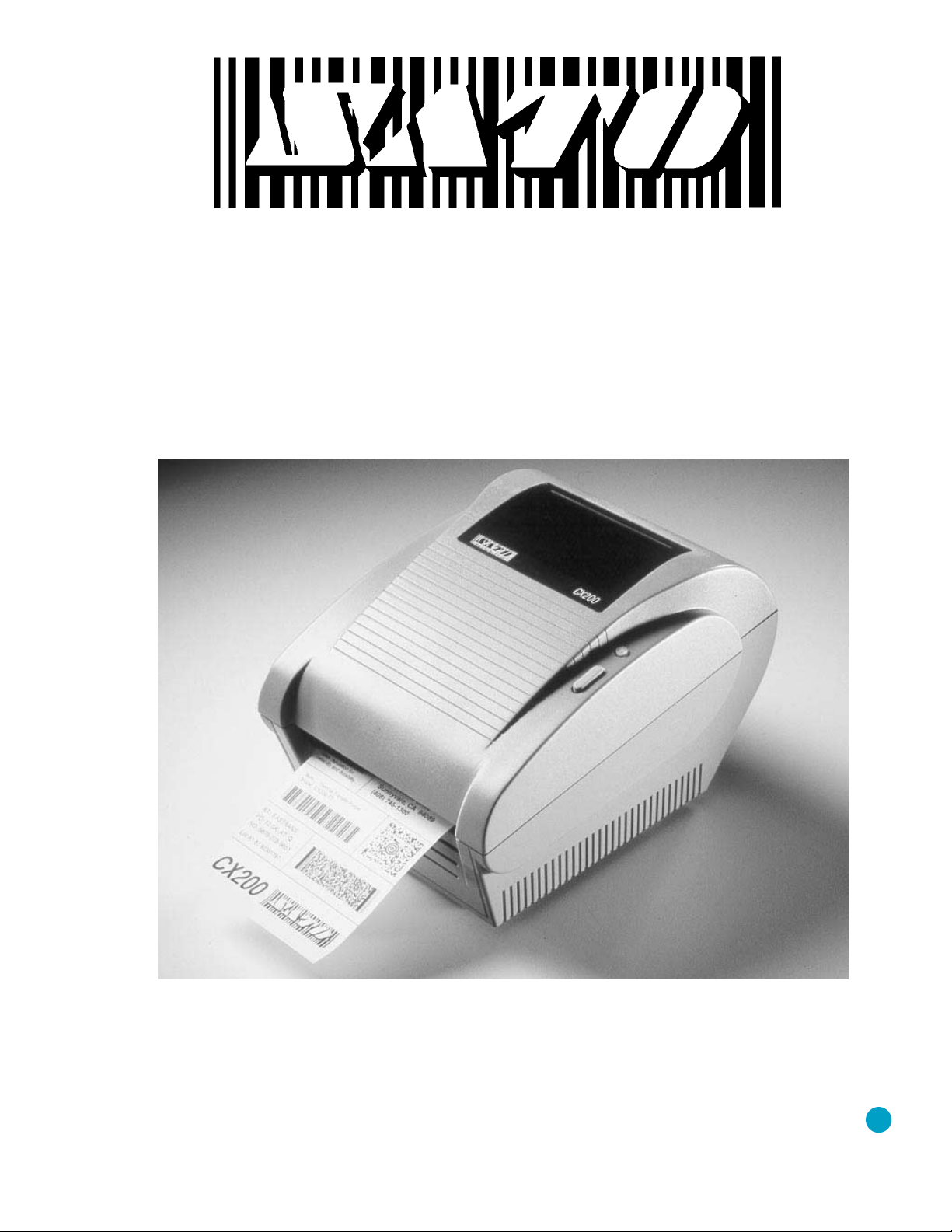
CX200
Desktop Printer
®
Programming
Guide
Click to Display
Document List
Page 2

SATO America, Inc.
10350-A Nations Ford Rd.
Charlotte, NC 28273
Main Phone:(704) 644-1650
Technical SupportHot Line:(704) 644-1660
Fax:(704) 644-1661
http://www.satoamerica.com
© Copyright 1998
SATO America, Inc.
Warning: This equipment has been tested and found to comply with the limits for a
Class B computing device pursuant to Part 15 of the FCC rules. These limits are
designed to provide reasonable protection against harmful interference in a
residential installation. This equipment generates, uses, and can radiate radio
frequency energy and, if not installed in accordance with the instruction may cause
harmful interference to radio communications.However, there is no guarantee that
interference will not occur in a particular installation. If this equipment does cause
harmful interference to to radio or television reception, which can be determined by
turning the equipment off and on, the user is encouraged to try and correct the
interference by one or more of the following measures:
• Reorient or relocate the receiving antenna.
• Increase the separation between the equipment and the receiver.
• Connect the equipment into an outlet or a circuit different from that to
which the receiver is connected.
• Consult an experienced radio/TV technician for help.
Caution: The FCC warns the users that changes or modifications of the unit not
expressly approved by the party responsible for compliance could void the user’s
authority to operate the equipment.
All rights reserved. No part of this document may be reproduced or issued to third
parties in any form whatsoever without the express permission of SATO America, Inc.
The material in this document is provided for general information and is subject to
change without notice. SATO America, Inc. assumes no responsibility for any errors
that might appear.
Page 3

TABLE OF CONTENTS
CX200 Programming Guide
Introduction . . . . . . . . . . . . . . . . . . . . . . . . . . . . . 1
The SATO Programming Language . . . . . . . . . . . . . . . . . . 1
Selecting Protocol Control Codes . . . . . . . . . . . . . . . . . . . 2
Using Basic . . . . . . . . . . . . . . . . . . . . . . . . . . . . . . 2
The Print Area . . . . . . . . . . . . . . . . . . . . . . . . . . . . 4
Rotated Fields . . . . . . . . . . . . . . . . . . . . . . . . . . . . 7
Command Default Settings . . . . . . . . . . . . . . . . . . . . . . 8
Printer Configuration . . . . . . . . . . . . . . . . . . . . . . . . . 8
Label Sensing . . . . . . . . . . . . . . . . . . . . . . . . . . . . 9
Command Code Page Reference . . . . . . . . . . . . . . . . . . . 10
Bar Codes . . . . . . . . . . . . . . . . . . . . . . . . . . . . . 11
Bar Codes, Expansion . . . . . . . . . . . . . . . . . . . . . . . 16
Bar Codes, Variable Ratio . . . . . . . . . . . . . . . . . . . . . 17
Base Reference Point . . . . . . . . . . . . . . . . . . . . . . . 19
Characters, Custom Designed . . . . . . . . . . . . . . . . . . . 21
Character Expansion . . . . . . . . . . . . . . . . . . . . . . . 23
Character, Fixed Spacing . . . . . . . . . . . . . . . . . . . . . 25
Character Pitch . . . . . . . . . . . . . . . . . . . . . . . . . . 26
Character, Proportional Spacing . . . . . . . . . . . . . . . . . 28
Clear Print Jobs & Memory . . . . . . . . . . . . . . . . . . . . 29
Continuous Forms Printing . . . . . . . . . . . . . . . . . . . . 30
Copy Image Area . . . . . . . . . . . . . . . . . . . . . . . . . 31
Cutter Command . . . . . . . . . . . . . . . . . . . . . . . . . 33
Fonts, U, S, M, OA, OB, XU, XS and XM . . . . . . . . . . . . . 34
Fonts, WB,WL, XB and XL . . . . . . . . . . . . . . . . . . . . 36
Form Feed . . . . . . . . . . . . . . . . . . . . . . . . . . . . 38
Form Overlay Recall . . . . . . . . . . . . . . . . . . . . . . . 39
Form Overlay Store . . . . . . . . . . . . . . . . . . . . . . . . 40
Graphics, Custom . . . . . . . . . . . . . . . . . . . . . . . . . 41
Graphics, PCX . . . . . . . . . . . . . . . . . . . . . . . . . . . 43
Journal Print . . . . . . . . . . . . . . . . . . . . . . . . . . . 44
Lines and Boxes . . . . . . . . . . . . . . . . . . . . . . . . . . 45
Line Feed . . . . . . . . . . . . . . . . . . . . . . . . . . . . . 47
Off-Line . . . . . . . . . . . . . . . . . . . . . . . . . . . . . . 48
Postnet . . . . . . . . . . . . . . . . . . . . . . . . . . . . . . 49
Print Darkness . . . . . . . . . . . . . . . . . . . . . . . . . . 50
Print Length, Expanded . . . . . . . . . . . . . . . . . . . . . . 51
Print Position . . . . . . . . . . . . . . . . . . . . . . . . . . . 53
Print Quantity . . . . . . . . . . . . . . . . . . . . . . . . . . . 55
Print Speed . . . . . . . . . . . . . . . . . . . . . . . . . . . . 56
Repeat Label . . . . . . . . . . . . . . . . . . . . . . . . . . . 57
Replace Data (Partial Edit) . . . . . . . . . . . . . . . . . . . . 58
Reverse Image . . . . . . . . . . . . . . . . . . . . . . . . . . 60
Rotate, Fixed Base Reference Point . . . . . . . . . . . . . . . . 62
Rotate, Moving Base Reference Point . . . . . . . . . . . . . . . 64
Sequential Numbering . . . . . . . . . . . . . . . . . . . . . . 66
Start/Stop Label . . . . . . . . . . . . . . . . . . . . . . . . . 68
SATOCX200PrintersPN9001055 Rev. EPage - i
Page 4

Expanded Memory Option Commands . . . . . . . . . . . . . . 69
Fonts, TrueType Recall . . . . . . . . . . . . . . . . . . . . 70
Fonts, TrueType Store . . . . . . . . . . . . . . . . . . . . 71
Graphics, Custom Recall . . . . . . . . . . . . . . . . . . . 72
Graphics, Custom Store . . . . . . . . . . . . . . . . . . . . 73
Graphics, PCX Recall . . . . . . . . . . . . . . . . . . . . . 75
Graphics, PCX Store . . . . . . . . . . . . . . . . . . . . . 76
Initialize . . . . . . . . . . . . . . . . . . . . . . . . . . . 77
Slot Select . . . . . . . . . . . . . . . . . . . . . . . . . . 78
Status . . . . . . . . . . . . . . . . . . . . . . . . . . . . . 79
Two-Dimensional Symbols . . . . . . . . . . . . . . . . . . . . 80
Maxicode . . . . . . . . . . . . . . . . . . . . . . . . . . . 81
PDF417 . . . . . . . . . . . . . . . . . . . . . . . . . . . . 83
Configuration Commands . . . . . . . . . . . . . . . . . . . . . . 85
Calibrate Sensor . . . . . . . . . . . . . . . . . . . . . . . . . 86
Custom Protocol Command Codes Download . . . . . . . . . . 87
Label Tear-Off . . . . . . . . . . . . . . . . . . . . . . . . . . 89
Print Darkness Fine Adjustment . . . . . . . . . . . . . . . . . 90
Print Test Label . . . . . . . . . . . . . . . . . . . . . . . . . . 91
Set Print Mode . . . . . . . . . . . . . . . . . . . . . . . . . . 92
Set RS232 Parameters . . . . . . . . . . . . . . . . . . . . . . 93
Set Sensor Type . . . . . . . . . . . . . . . . . . . . . . . . . 94
Backfeed Enable . . . . . . . . . . . . . . . . . . . . . . . . . 95
Page - iiPN9001055 Rev. ESATOCX200Printers
Page 5

CX200 PROGRAMMING GUIDE
INTRODUCTION
This section presents the commands that are used with the SATO CX printers to
produce labels with logos, bar codes and alphanumeric data.
The following information is presented in this section:
• The SATO Programming Language
• Selecting Protocol Control Codes
• Using Basic
• The Print Area
• Printer Configuration
• Command Codes
THE SATO PROGRAMMING LANGUAGE
A programming language for a printer is a familiar concept to most programmers. It is
a group of commands that are designed to use the internal intelligence of the printer.
The commands, which are referred to as SATO Command Codes, contain
non-printable ASCII characters (such as <STX>, <ETX>, <ESC>) and printable
characters. These commands must be assembled into an organized block of code to be
sent as one data stream to the printer, which in turn interprets the command codes
and generates the desired label output. The programmer is free to use any
programming language available to send the desired data to the printer.
The command codes used are based upon “Escape” (1B hexadecimal) sequences.
Typically there are four types of command sequences:
<ESC>{Command}
These commands generally tell the printer to perform a specific action, like “clear the
memory.”
<ESC>{Command} {Data}
Commands with this format tell the printer to perform a specific action which is
dependent upon the following data, like “print X labels”, where the value for X is
contained in the data.
<ESC>{Command} {Parameter}
These commands set the operational parameters of the printer, like “set the print
speed to 3.”
<ESC> {Command} {Parameter} {Data}
SATOCX200PrintersPN9001055 Rev. EPage 1
Page 6

CX200 Programming Guide
Some commands can contain both Parameter and Data elements, such as “print a
Code 39 symbol containing the data.”
SELECTING PROTOCOL CONTROL CODES
Protocol codes are the special control characters that prepare the printer to receive
instructions. For example, the <ESC> character tells the printer that a command
code will follow.
The Protocol Control Code set set is made up of six special characters. The Standard
Protocol Control codes are non-printable characters. They can be changed to
printable characters using the Protocol Control code download command. This may
be useful on host computers using protocol converters or in an application where
non-printable ASCII characters cannot be sent from the host. This manual uses the
Standard Protocol Control codes for all of the examples.
The Protocol Control codes must be downloaded from the host using the <ESC>LD
command (see Page 90). Once they are downloaded, the printer will not respond to
standard protocol codes. The current protocol codes active in a printer can be
determined by printing a Test Label (see CX200 User’s Guide, Page 9).
USING BASIC
It may be useful to test your printer using a BASIC program on a PC. You may also
write your actual production programs in BASIC. Whatever the reason, if you will be
working in BASIC, some of the following hints may help you get started:
1. Set the WIDTH of the output device to 255 characters to avoid automatically
CONTROL
CHARACTER
STX 02 Start of Data
ETX 03 End of Data
ESC 1B Command code to follow
ENQ 05 Not Used on CX200
CAN 18 Not Used on CX200
Off-Line 40 Take printer Off-Line
HEX VALUE DESCRIPTION
sending <CR> and <LF> characters after every line. The command string
should be continuous and uninterrupted by <CR> and/or <LF> commands.
The examples given in this manual are printed on separate lines because they
will not fit on one line and do not contain any <CR> and/or <LF> characters. If
these characters are needed, they are explicitly noted by the inclusion of <CR>
and <LF> notations.
2. If you are using the printer’s RS232 interface, it is necessary to set the COM port on
the PC such that the CTS and DSR signals will be ignored. Send your OPEN
“COM” statement in the following way:
Page 2PN9001055 Rev. ESATOCX200Printers
Page 7

CX200 Programming Guide
OPEN “COM1:9600,E,8,1,CS,DS” AS #1
This sets the RS232 communication parameters of the host PC’s COM1 port for 9600
baud, Even parity, 8 Data bits, 1 Stop bit and directing the port to ignore the CTS
and DSR control signals.
3. You may want to minimize keystrokes and program size by assigning the <ESC>
character to a string variable since this character is used quite often.
The following two examples in BASIC show a typical example using these hints. Both
of these examples use the Standard Protocol codes.
Printing with the Parallel Port
5 REM Parallel Example Identifies the program as a parallel port
print label. The “REM” prevents this
data from being sent to the printer and
displays it only on the screen.
10
E$=CHR$(27) Sets the “E$” string as an <ESC>
character
20
WIDTH “LPT1:”,255 Sets the width of the output to 255
characters
30
LPRINT E$;"A"; Sends an “<ESC>A” command code to
the LPT1 parallel port
40
LPRINT E$;"H400";E$;"V100";E$;"WL1SATO"; Sends the data “SATO” to be to be
placed 400 dots horizontally and 100
dots vertically on the label and printed in
the “WL” font.
50
LPRINT E$;"Q1"; Instructs the printer to print one label.
60
LPRINT E$; “Z”; Tells the printer that the last command
has been sent. The printer can now
create and print the job.
Printing with the RS232 Port
5 REM RS232 Example Identifies the program as a RS232 port
print label. The “REM” prevents this
data from being sent to the printer and
displays it only on the screen.
10
E$=CHR$(27) Sets the “E$” string as an <ESC>
character.
20
OPEN “COM1:9600,N,8,1,CS,DS” AS #1 Opens the COM1 port for output and
sets the parameters as 9600 baud, No
parity, 8 Data bits, 1 Stop bit and
instructs the port to ignore the CTS and
DSR control signals.
30
PRINT #1,CHR$ (2); Sends an <STX> (ASCII Code a
decimal “2”) to the printer instructing it
to prepare to receive a message.
40
PRINT #1,E$;"A"; Sends an “<ESC>A” command code to
Print Port #1 opened by statement 20
above.
SATOCX200PrintersPN9001055 Rev. EPage 3
Page 8
CX200 Programming Guide
50 PRINT #1, E$;"H400";E$;"V100";E$;"WL0SATO"; Sends the data “SATO” to be to be
60
PRINT #1, E$;"Q1"; Instructs the printer to print a quantity of
70
PRINT #1, E$; “Z”; Tells the printer that the last command
80
PRINT #1,CHR$ (3); Sends an <ETX> (ASCII Code decimal
THE PRINT AREA
The maximum print area is 7 inches long in the standard mode and 14 inches long if
the length is expanded with the Expanded Print Length command. Most of your label
applications will fit into this area, therefore, it is important to understand how to
work with labels that do not use the entire print area. The goal is to help you avoid
printing where no label exists, which may lead to print head damage, not to mention
the frustration when you cannot see the printed output.
placed 400 dots horizontally and 100
dots vertically on the label and printed in
the “WL” font.
one label.
has been sent. The printer can now
create and print the job.
“3”) to the printer telling it that this is the
end of the message.
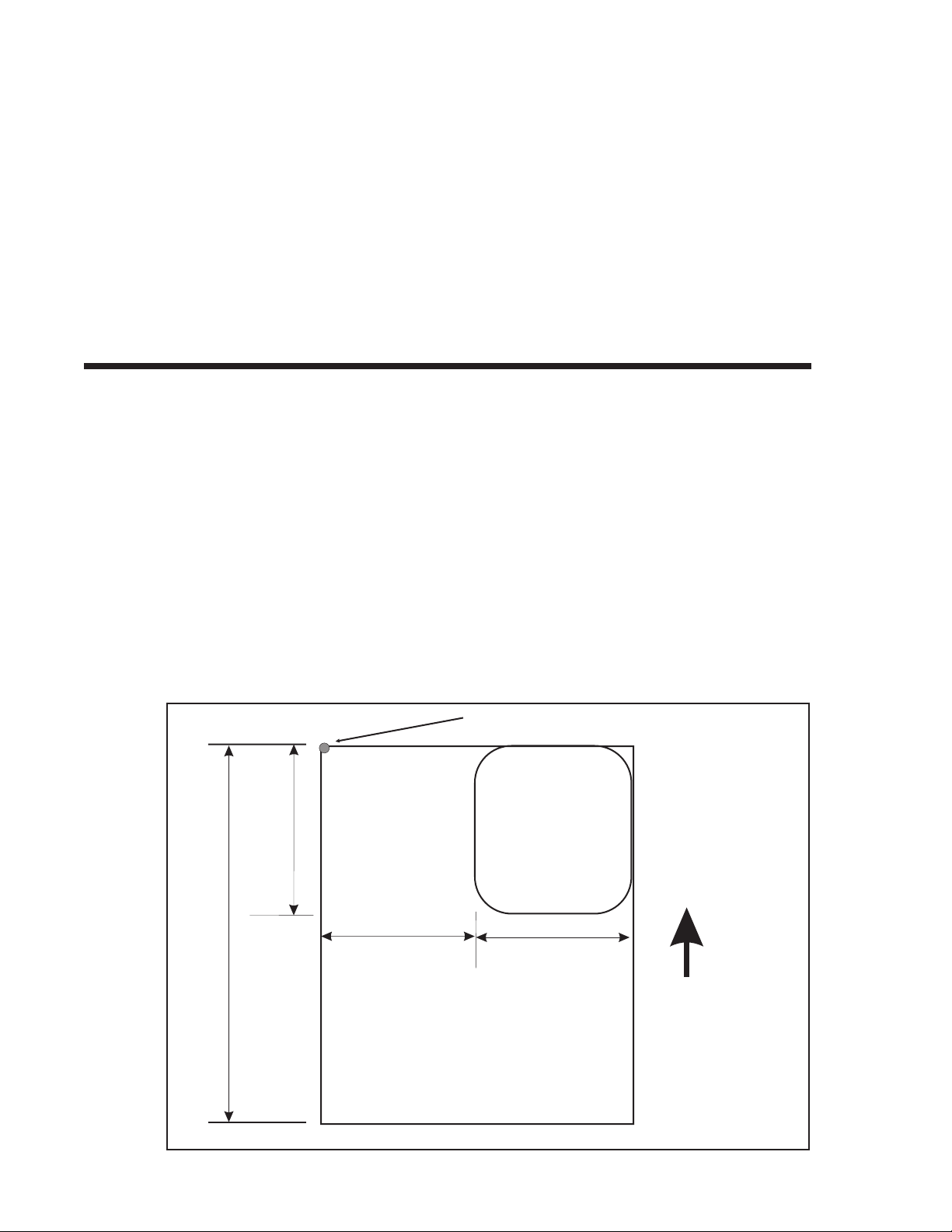
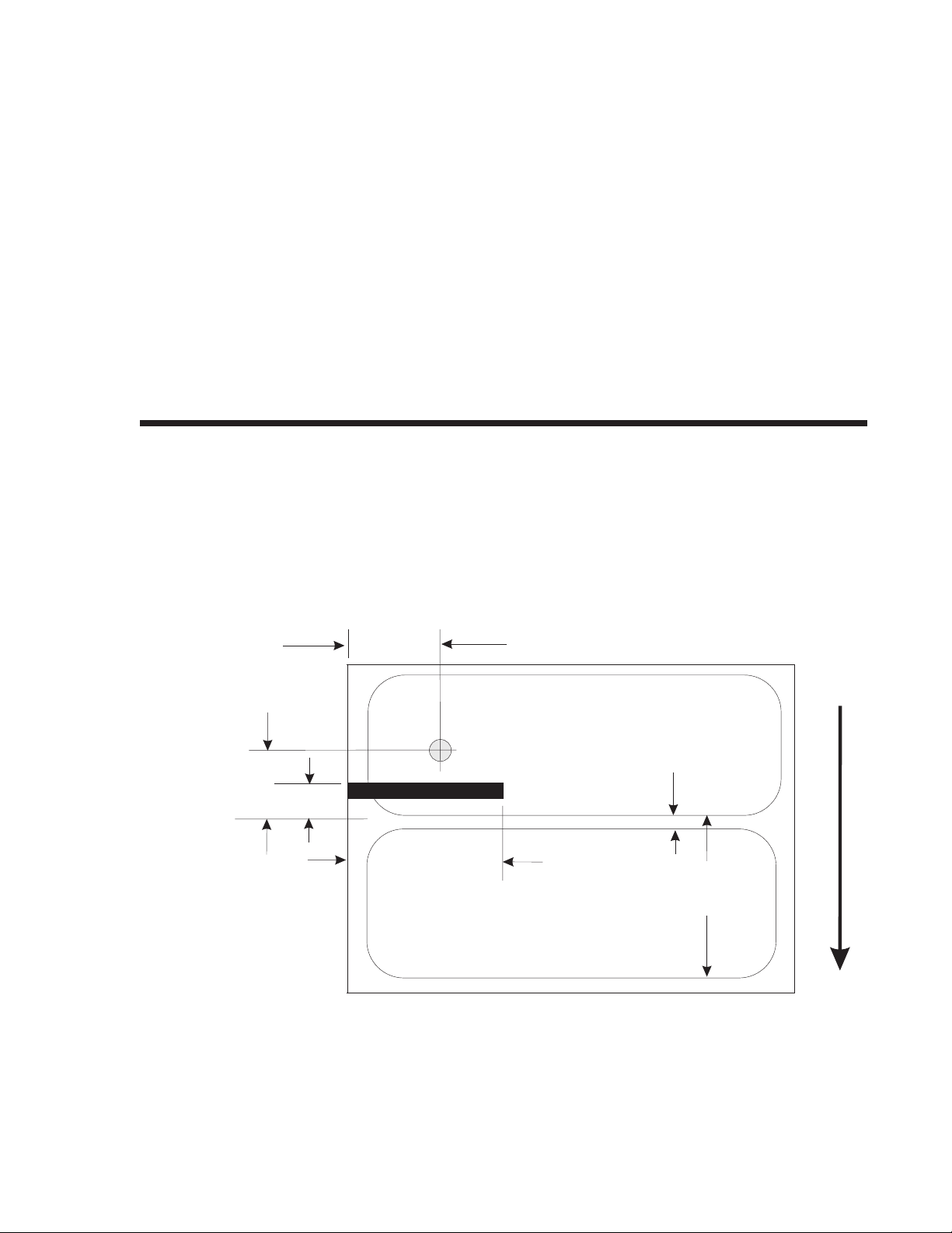
The diagram below illustrates the print area for a sample 2 inch wide by 3 inch long
label placed within this area. As can be seen, your label will be oriented against the
inside left edge of the printer as viewed from the front (label exit) of the printer. The
normal reference point is located at the H1, V1 position of the print area in the
normal print orientation (no rotation).
Normal Reference Point
H1, V1
3"
label
length
Your
Label
7"
Print
Area
2.1"
label Width
2.0"
from Edge
Direction
Label Feed
4.1"
Print Area
Page 4PN9001055 Rev. ESATOCX200Printers
Page 9

The base refernece point is always on the right edge of the print head as you face the
front (label exit) of the printer. If you are using a label that is narrower than the
maximum print width, you may have to adjust the base reference point of the
Left-Hand printer to correctly position the print area. There are two methods
available as follows:
1. Send the Base Reference Point command as part of your data to the printer to set a
new base reference point for your label.
Calculate the distance (in dots) from the normal base reference point to the closest
edge of the label. If you wanted to move the print area over to the left (as viewed
from the front or label exit end of the printer) 2.1 inches:
Label Width = 2.0" x 25.4 mm/in x 8 dpmm = 406 dots
The new base reference point then becomes:
New Base Reference Point = max print width - label width
= 832 dots - 406 dots = 426
Issue the Base Reference Point command after the Start command in your data
stream.
<ESC>A3H0426V0001
This resets the reference point for all the following data.
Note: After the reference point is moved, you can no longer print on the 426 dot
“margin” unless the reference point is reset.
2. Use the normal base reference point from the print area and use the horizontal
position for each field to properly locate it on the label.
Calculate the distance (in dots) from the normal base reference point to the closest
edge of the label.
Shift Distance = 2.1" x 25.4 mm/in x 8 dpmm = 426 dots
New Base Reference Point = 832 dots - 426 dots = 406
Each <ESC>H command would have the value “406” added to it to correctly
position each field.
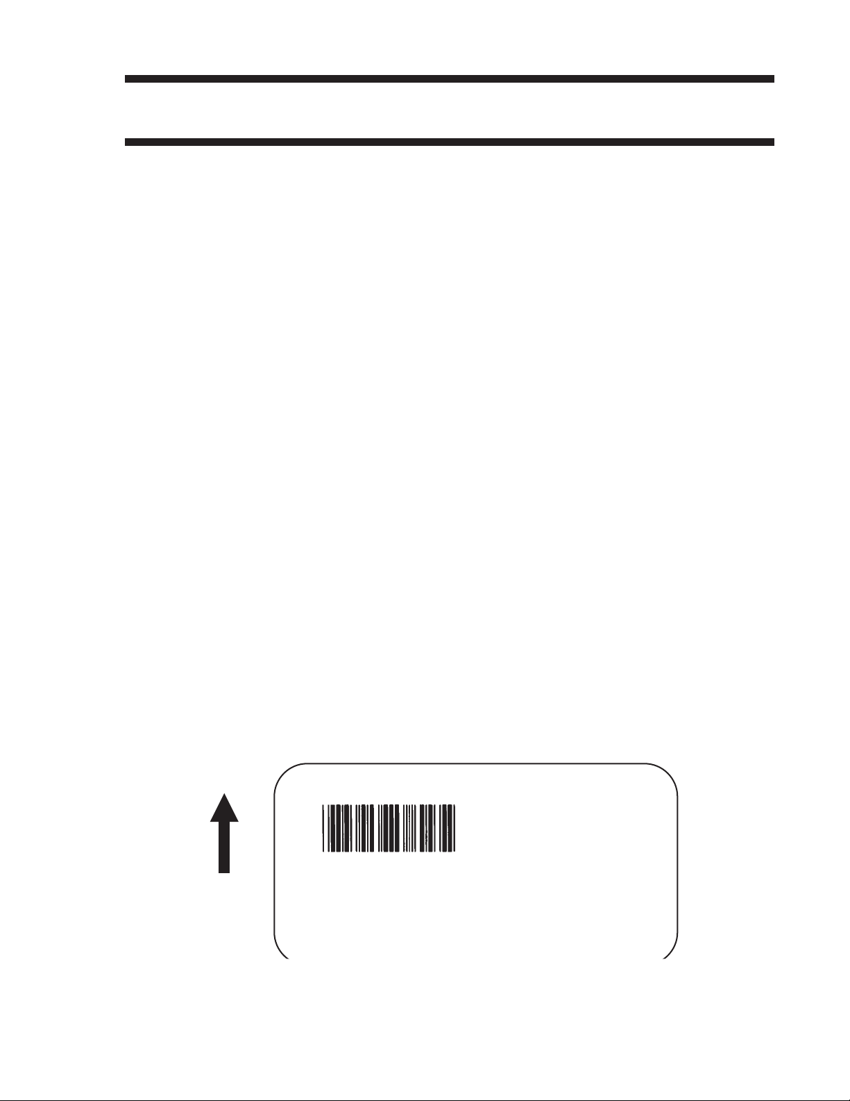
The Command Code subsection contains a sample label output for each command
code. These samples reflect how the printed information would appear on a five inch
wide label (see illustration). If you want to test any of the sample label outputs and
are using labels less than five inches in width, you will have to adjust the positioning
accordingly so that the printer does not try to print where there is no label.
You must be careful not to print off the label surface as the label provides a heat sink
for the print head elements. Doing so will cause irreparable damage to the head. This
damage is not covered under the print head warranty.
SATOCX200PrintersPN9001055 Rev. EPage 5
Page 10
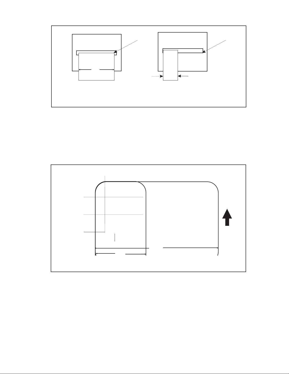
CX200 Programming Guide
Base Reference
Point, H=0001
Label
4"
For example, the following illustrates a sample data stream and the resulting label
assuming a four inch wide label:
<ESC>A
<ESC>H0050<ESC>V0100<ESC>L0303<ESC>MSATO
<ESC>H0050<ESC>V0200<ESC>B103100*SATO*
<ESC>H0070<ESC>V0310<ESC>L0101<ESC>USATO
<ESC>Q1<ESC>Z
Label
2"
Base Reference
Point, H=0001
H=50
V=100
SATO
V=200
*SATO*
V=310
If you are using a two inch wide label, the entire image may not appear on your label.
By adding the following Base Reference Point command to the second line of the data
stream, the base reference point will be changed, causing the image to be shifted over
toward the inside of the printer where it can be printed on the narrower label.
*SATO*
SATO
H=70
2"
Unshifted Print Area
4.1"
<ESC>A
<ESC>A3H0406V0001
<ESC>H0050<ESC>V0100<ESC>L0303<ESC>MSATO
<ESC>H0050<ESC>V0200<ESC>B103100*SATO*
<ESC>H0170<ESC>V0310<ESC>L0101<ESC>USATO
<ESC>Q1<ESC>Z
Page 6PN9001055 Rev. ESATOCX200Printers
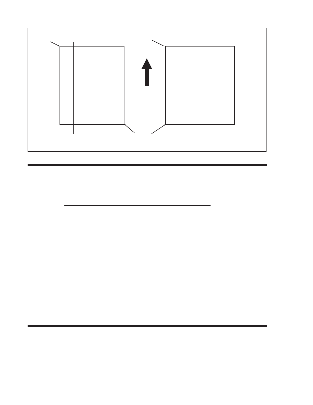
Page 11

CX200 Programming Guide
SATOSATO
Original image must be moved towards
the left (facing the printer) to make it
The image reference point is set at the left edge (facing the printer) of the label so
that it can be printed on a 2 inch wide label.
Note: The printers will not “wrap” images that extend beyond the print area. If any part
of a character or image extends beyond the print area, it will disappear.
For more information, see the Base Reference Point command description.
ROTATED FIELDS
*SATO*
*SATO*
SATO
print on a 2" wide label.
*SATO*
*SATO*
SATO
2" Label
4.1"
The printers can rotate each print field in 90° increments using the Rotate command.
There are two variations of this command.
• <ESC>% - The field rotates, but the base reference point for the field
remains the same.
• <ESC>R - The field and the base reference point rotate.
The following data stream will rotate the print field but will not change the base
reference point of the field:
<ESC>A<ESC>%1<ESC>V800<ESC>H200<ESC>L0202<ESC>WB1E<ESC>Q1<ESC>Z
The following data stream will rotate both the field and the base reference point for
that field:
<ESC>A<ESC>R<ESC>V0200<ESC>H0100<ESC>L0202<ESC>P02<ESC>WB1E<ESC>Q1<ESC>Z
SATOCX200PrintersPN9001055 Rev. EPage 7
Page 12
CX200 Programming Guide
Base
Ref
Point
V=800
H=200
E
“%1”
COMMAND DEFAULT SETTINGS
There are some types of commands that must have a value specified before a label
can be printed. If the data stream does not contain these commands, a “default” value
is assumed. The commands and the corresponding default values are:
Base
Ref
Point
Label
Feed
Direction
New
Base
Ref
Point
V=200
E
H=100
“R”
COMMAND DEFAULT NOTE
Print Rotation 0° (1)
Vertical Reference Point 0 (1)
Horizontal Reference Point 0 (1)
Character Pitch 2 (1)
Base Reference Point H=0, V=0 (2)
Character Expansion 1 (1)
Print Darkness 3 (1)
Print Speed 3 ips (2)
NOTES:
(1) The settings for these commands will revert to the default value when the printer
receives an <ESC>Z or an <ESC>*.
(2) These values transmitted with these commands will remain in effect until a new
command is received.
PRINTER CONFIGURATION
The CX200 oprinters are different from other SATO models in that they do not use
DIP switches for printer configuration. Instead, all printer configuration is done via
software commands. The parameters that can be configured are:
• Sensor Calibration
• Protocol Codes
Page 8PN9001055 Rev. ESATOCX200Printers
Page 13
Because there are no DIP switches to indicate the current printer settings, a Test
Label can be printed that lists the active settings in the printer. This Test Label lists all
of the information a user needs to ascertain the printer configurtation. Test Labels
can be printed out by sending a command via software (see Page 93) or by using the
FEED and On-Line/Off-Line Indicator buttons on the control panel (see Page 7 of the
CX200 User’s Guide).
LABEL SENSING
The CX200 printers can use eye-mark (black bar), gap or notch label sensing. The gap
and notch sensor is a transmissive or see-thru type with an infrared light source
directed through the label/ribbon combination from above and detected by a separate
sensor underneath the label. A reflective sensor is used to detect eye-marks printed
on the bottom of the label liner or tag. The eye-mark must not reflect more than 12%
of the light. Since the same receiving sensor is used for all three types of sensing, it
must be calibrated with the media that will be used. The ribbon must be installed
while the calibration is being performed.
CX200 Programming Guide
• Print Darkness Range
• Sensor Type
• RS232 Parameters
• Label Tear-Off Position
• Backfeed Enable/Disable
Print Head
0.65"
(16.5mm)
0.75"
(19mm)
See
Note 1
Fixed Position
Sensor
Eye-Mark on
underneath side
of label
Min. Length = 1"
(25.4mm)
Gap, Notch or Bar Width
Min: 0.125" (3.2mm)
Max: 1.0" (25mm)
Min Label Pitch
0.375" (9.5mm)
Left Label Edge
Note 1: The the trailing-edge of the black eye-mark can be positioned anywhere
within the 0 to +98mm range of sensor offset adjustment and the first print line
(V=000) can be adjusted to the desired position using the <ESC>CB Label
Tear-Off command. If the pitch offset is 11mm (the factory setting), placing the
eye-mark trailing edge at 8mm will place the first print position at the top edge
of the label.
Label Feed Direction
SATOCX200PrintersPN9001055 Rev. EPage 9
Page 14

CX200 Programming Guide
When calibrating the printer sensors, the gap or eye-mark sensor type must be
selected first using the <ESC>CI command (see page 94) and then the Direct
Thermal or Thermal Transfer print mode must be specified with an <ESC>CP
command (see page 92). These two commands are followed by an <ESC>CA
calibrate command (see page 86) to instruct the printer to preform the calibration
procedure. The resulting calibration values are stored in the printer and used until
the unit is recalibrated. A separate value is stored for direct thermal and thermal
transfer modes because the settings will differ significantly because of the inclusion of
the ribbon for thermal transfer. For example, the following command stream will
calibrate the printer in the thermal transfer mode for gap sensing:
<ESC>A<ESC>CP1<ESC>CI2<ESC>CA<ESC>Z
COMMAND CODE PAGE REFERENCE
This section contains all the printer Command Codes. The commands must be sent to
the printer in an organized fashion in order for the label(s) to print.
The purpose of this section is to:
1. Explain the different commands and provide examples of their usage.
2. To provide a detailed reference for programming.
Each command begins on a separate page with its own heading. A uniform layout is
used to help you find key information about each command. For each Command
Code in this section, there will be a sample data input stream to the printer and the
expected print output. By studying the examples, you can learn how to use the
particular command within a whole block of printer code. Pay particular attention to
the “Special Notes” with each command to learn other important information.
The subject commands are highlighted in bold letters in the Reference Sheets. There
are two parts of most, but not all, commands. The first is the command character
which immediately follows the <ESC> code. It is always an upper case alpha or a
special character (such as an “&” or a “%”). It is never a lower case alpha character. If
the command requires additional variable information, it is represented by a group of
lower case alpha characters immediately following the command character. For
example, if an aaaabb is listed following the basic command, the printer will look
for six characters immediately following the command. The first four would represent
the value of aaaa and the next two the value of bb.
The maximum number of characters defined in a parameter is represented by the
number of characters shown in the command structure. For example, a command
followed by an aaaa can have up to four characters. In general, commands with only
one parameter following the command can be entered without the leading zeroes. In
the above example, you could enter either “809” or “0809”. However, certain
commands require the exact number of matching characters. A command with two
parameters listed following the command code, such as aaaabbbb require the exact
number of digits to be entered. If the value of aaaa is “800” and the value of bbbb
is “300”, then the parameters must be entered as “08000300”. It is recommended
that you make it a practice to always enter leading zeros to prevent any mistakes.
Page 10PN9001055 Rev. ESATOCX200Printers
Page 15

Bar Codes
Command Structure 1:3 narrow/wide bar ratio: <ESC>Babbcccd
2:5 narrow/wide ratio: <ESC>BDabbcccd
1:2 narrow/wide bar ratio: <ESC>Dabbcccd
a = Bar Code Symbol
0 Codabar
1 Code 39
2 Interleaved 2 of 5 (I 2/5)
3 UPC-A / EAN-13
4 EAN-8
A MSI
C Code 93
E UPC-E
F Bookland
G Code 128
I UCC 128
CX200 Programming Guide
bb = Number of dots (01-12) for narrow bar and narrow space
ccc = Bar height in dots (001-600)
d = UCC 128 only. Not used for other bar code types
0 No human readable text
1 Human readable at top
2 Human readable at bottom
Example: <ESC>BD103200
Placement: Immediately preceding data to be encoded
Default: None
Command Function To print bar code images on a label. With this command, there are 13
standard bar code symbologies available to be printed and three two
dimensional symbols (see Two Dimensional bar code symbols
starting on Page 80).
SATOCX200PrintersPN9001055 Rev. EPage 11
Page 16

CX200 Programming Guide
Input to Printer
<ESC>A
<ESC>H0025<ESC>V0025<ESC>B103100*CODE39*
<ESC>H0155<ESC>V0130<ESC>XS*CODE39*
<ESC>H0025<ESC>V0200<ESC>BD20210045676567
<ESC>H0075<ESC>V0310<ESC>XM45676567
<ESC>H0025<ESC>V0375<ESC>BD30215001234567890
<ESC>H0025<ESC>V0950<ESC>BA03100123455
<ESC>H0095<ESC>V1060<ESC>XS12345
<ESC>H0025<ESC>V1125<ESC>BC03100081234ABCD
<ESC>H0080<ESC>V1240<ESC>XS1234ABCD
<ESC>H0525<ESC>V0025<ESC>B002100A12345B
<ESC>H0565<ESC>V0135<ESC>XS12345
<ESC>H0475<ESC>V0200<ESC>BD303100123456789012
<ESC>H0525<ESC>V0375<ESC>BD4031001234567
<ESC>H0525<ESC>V0550<ESC>DE03100123456
<ESC>H0500<ESC>V0600<ESC>OB0
<ESC>H0533<ESC>V0655<ESC>OB123456
<ESC>H0350<ESC>V0725<ESC>D30315009827721123
<ESC>L0101<ESC>H0320<ESC>V0800<ESC>OB0
<ESC>H0365<ESC>V0878<ESC>OB98277
<ESC>H0505<ESC>V0878<ESC>OB21123
<ESC>H0665<ESC>V0760<ESC>BF0313021826
<ESC>H0680<ESC>V0730<ESC>OB21826
<ESC>H0425<ESC>V1125<ESC>D30315000633895260
<ESC>L0101<ESC>H0395<ESC>V1200<ESC>OB0
<ESC>H0440<ESC>V1278<ESC>OB06338
<ESC>H0580<ESC>V1278<ESC>OB95260
<ESC>H0730<ESC>V1155<ESC>BF0314024
<ESC>H0745<ESC>V1125<ESC>OB24
<ESC>H0325<ESC>V0950<ESC>BG03100>GAB>B789>C123456
<ESC>H0435<ESC>V1055<ESC>XSAB789123456
<ESC>Q1<ESC>Z
Note: Carriage Returns and Line Feeds have been added to the command listing
for clarity and should not be included in the actual data stream.
Page 12PN9001055 Rev. ESATOCX200Printers
Page 17
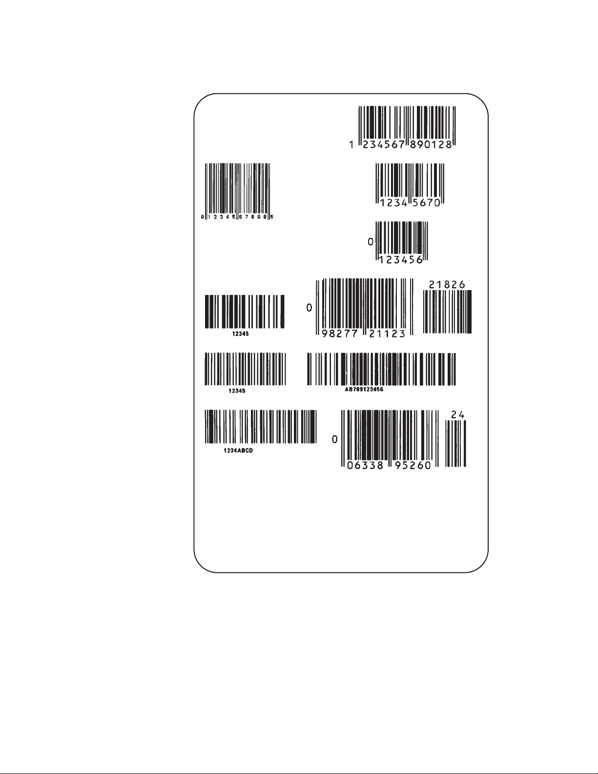
Printer Output
CX200 Programming Guide
SATOCX200PrintersPN9001055 Rev. EPage 13
Page 18
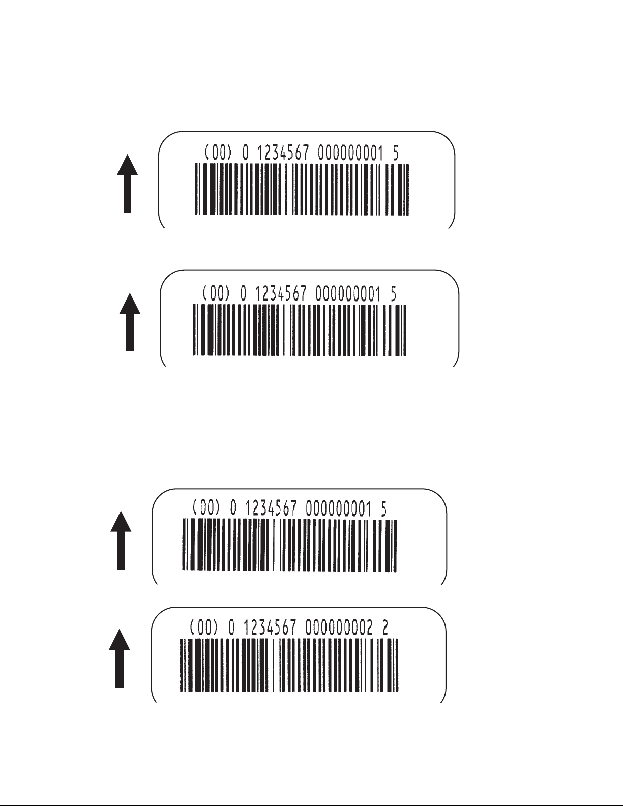
CX200 Programming Guide
UCC-128 Without Incrementing
<ESC>A
<ESC>H0100<ESC>V0100<ESC>BI07150101234567000000001
<ESC>Q2<ESC>Z
With Incrementing
<ESC>A
<ESC>H0100<ESC>V0100<ESC>F001+001<ESC>BI07150101234567000000001
<ESC>Q2<ESC>Z
Page 14PN9001055 Rev. ESATOCX200Printers
Page 19

CX200 Programming Guide
Special Notes 1. UPC and EAN bar codes are not affected by the different types of
narrow to wide ratios. Instead, the <ESC>D command adds
descender bars to these codes where needed to meet UPC
specifications. The <ESC>BD command puts decender bars and
human readable text below the symbol.
2. The Code 128, UCC 128, MSI, and Code 93 bar codes are not
affected by the narrow to wide ratios.
3. The Codabar and Code 39 bar codes are affected by the Character
Pitch command. This command must be placed before the Bar
Code command.
4. See Appendix B for more specific instructions and detailed
information regarding individual bar code symbols.
5. Because of their unique characteristics, two-dimensional symbols
are covered separately (see Page 80).
6. For UCC128, the FNC1 code is automatically inserted and the Mod
10 and Mod 103 check digits are automatically calculated.
7. For the MSI bar code, the check digit is not automatically calculated.
8. To select UPC-A, 11 digits of data is sent. The printer adds a “0”
and automatically generates the check digit. If 12 digits of data
are sent, the printer asumes an EAN-13 symbol and automatically
generates the check digit. The last digit of the bar code data is a
modulo 10 check digit. If 13 digits of data are sent to the printer,
the check digit is not created and must be supplied by the
programmer. It must be the last character of the 13 digit string.
SATOCX200PrintersPN9001055 Rev. EPage 15
Page 20
CX200 Programming Guide
Bar Codes, Expansion
Command Structure <ESC>BWaabbb
aa = Expansion factor by which the width of all bars and spaces
will be increased (01-12)
bbb = Bar height by dot (004-600 dots)
Example: <ESC>BW02100
Placement: Immediately follows the <ESC>BT command and
precedes data to be encoded.
Default: None
Command Function This command works together with the <ESC>BT command to
specify an expansion factor and the bar code height for the particular
symbol being printed.
Input to Printer:
Printer Output:
<ESC>A
<ESC>H0050<ESC>V0050<ESC>BT101030103
<ESC>BW04100*1234*
<ESC>Q1<ESC>Z
Special Notes 1. This command must be preceded by the Variable Ratio Bar Codes
<ESC>BT command (see Page 17).
2. The following bar codes will be affected by the Character Pitch
command: Codabar, Code 39 and Interleaved 2 of 5.
Page 16PN9001055 Rev. ESATOCX200Printers
Page 21
Bar Codes, Variable Ratio
Command Structure <ESC>BTabbccddee
a = Bar Code Symbol:
0 Codabar
1 Code 39
2 Interleaved 2 of 5
bb = Narrow space in dots (01-99)
cc = Wide space in dots (01-99)
dd = Narrow bar in dots (01-99)
ee = Wide bar in dots (01-99)
Example: <ESC>BT101030103
CX200 Programming Guide
Placement: Following print position commands and preceding
the <ESC>BW command.
Default: Current setting
Command Function To print a bar code with a ratio other than those specified through the
standard bar code commands (B,BD, and D). This is done through
individual control of each of the bar code elements (bars, spaces) as
shown above. Remember that this command only applies to the three
bar code types shown.
Input to Printer:
Printer Output:
<ESC>A
<ESC>H0050<ESC>V0050<ESC>BT101030103
<ESC>BW03100*1234*
<ESC>Q1<ESC>Z
SATOCX200PrintersPN9001055 Rev. EPage 17
Page 22

CX200 Programming Guide
Special Notes 1. This command must be immediately followed by the <ESC>BW Bar
Code Expansion command (see Page 16).
2. You may use only one variable ratio bar code per label.
3. If the data specified in this command is incorrect, the command is
ignored and the ratio used will be based on the previous setting.
Page 18PN9001055 Rev. ESATOCX200Printers
Page 23
Base Reference Point
Command Structure <ESC>A3H-aaaaVbbbb
- = This character is optional. When present, it specifies that
the horizontal offset is in the negative direction. If it is left out
the offset direction is positive.
aaaa = Horizontal Print Offset (-0832 to +0832)
bbbb = Vertical Print Offset (0001 to 1424)
Example: <ESC>A3H100V0050
Placement: Preceding all images that are based on the new base
reference point
CX200 Programming Guide
Default: Current V and H offset setting in the printer configuration
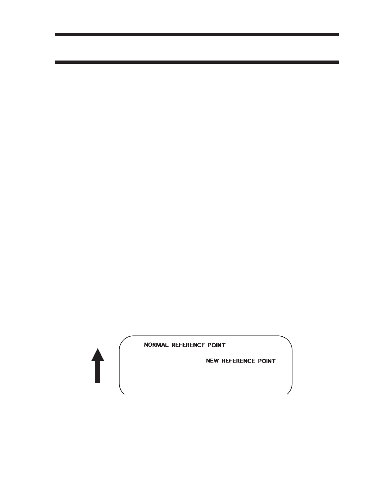
Command Function To establish a new base reference point for the current label. The
base reference point is the top left corner or “origin” from where all
print position commands are based.
This command may be very helpful when using labels less than four
inches wide to place images on the printable label surface. It may
also be used to move images past preprinted fields on a label.
Input to Printer:
Printer Output:
<ESC>A<ESC>L0202
<ESC>H0025<ESC>V0025<ESC>WB0MNORMALREFERENCE POINT
<ESC>A3H0300V0075
<ESC>H0100<ESC>V0050<ESC>WB0MNEWREFERENCE POINT
<ESC>Q1<ESC>Z
SATOCX200PrintersPN9001055 Rev. EPage 19
Page 24

CX200 Programming Guide
Special Notes 1. Use of this command will set the Vertical/Horizontal Offset setting of
the printer configuration until a new Base Reference Point
command is issued.
2. This command may be used more than once in a print job.
3. An alternative to using this command is to make changes to your
current Horizontal and Vertical Print Position commands (see
Page 53).
Example:
Let’s say the current base reference point is H=1, V=1 and you
wish to move all the fields on your label downward vertically by
150 dots. You could either (1) add the Base Reference Point
command or (2) change all the vertical position commands by an
additional 150 dots.
4. For a more detailed example of the Base Reference Point
command, see “Print Area” in this section (Page 4).
5. The CX200 printers will not “wrap” (i.e. if any part of a character or
image extends beyond the last print dot position, it will disappear
and not be visible on any part of the label).
Page 20PN9001055 Rev. ESATOCX200Printers
Page 25

Characters, Custom-Designed
Command Structure Store Command: <ESC>Tabcc
Recall Command: <ESC>Kab90cc
a = 1 16x16 matrix
2 24x24 matrix
b = Specifies the character encoding method for the data stream
H Hexadecimal characters
B Binary characters
cc = Memory location to store/recall the character. Valid memory
locations are 21 to 52 (counting in Hex) or “!” to “R” in Binary
(data) = Data to describe the character
CX200 Programming Guide
Example: <ESC>T1H3F
<ESC>K1H903F
See Appendix C for a more detailed explanation
Placement: The Store command is typically sent in its own data
stream to the printer, between the Start/Stop commands.
The Recall command is sent in a secondary data stream
to print the character,and follows any necessary position
or size commands.
Default: None
Command Function To allow for the creation, storage, and printing of custom characters,
such as special fonts or logos. Up to 50 individual characters may be
stored in the custom character volatile memory.
Printer Input See Appendix C for a detailed explanation.
<ESC>A
<ESC>T1H3F
0100038007C00FE01FF03FF87FFCFFFE07C007C007C007C007C007C007C007C0
<ESC>Z
<ESC>A
<ESC>H150<ESC>V100<ESC>L0505<ESC>K1H903F
<ESC>H350<ESC>V100<ESC>L1010<E SC>K1H903F
<ESC>Q1<ESC>Z
SATOCX200PrintersPN9001055 Rev. EPage 21
Page 26
CX200 Programming Guide
Printer Output
Special Notes 1. When printing the custom character using the <ESC>K Recall
command, the character is affected by the following commands:
Character Expansion (see Page 23)
Character Pitch (see Page 26)
Line Feed (see Page 47
Rotate, Fixed Base Reference Point (see Page 62)
Rotate, Moving Base Reference Point (see Page 64)
2. The characters are stored in volatile memory and must be reloaded
if the printer power is lost.
3. Do not use ASCII <CR> or <LF> characters (carriage return or line
feed) as line delimiters within the graphic data or the actual image
will not be printed as specified.
Page 22PN9001055 Rev. ESATOCX200Printers
Page 27
CX200 Programming Guide
Character Expansion
Command Structure <ESC>Laabb
aa = Multiple to expand horizontally (01-12)
bb = Multiple to expand vertically (01-12)
Example: <ESC>L0304
Placement: Preceding the data to be expanded
Default: <ESC>L0101
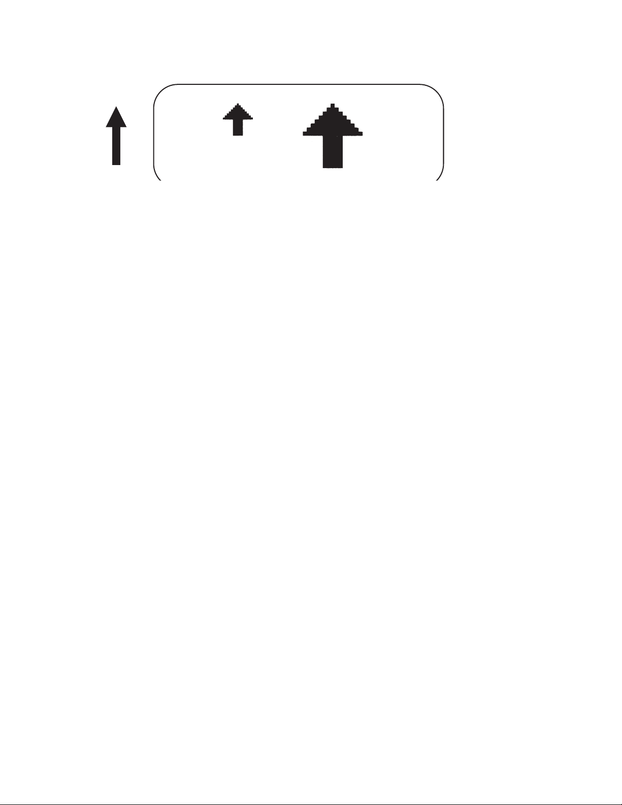
Command Function To expand characters independently in both the horizontal and
vertical directions. The command allows you to enlarge the base size
of each font (except the vector font) up to 12 times in either direction.
Expanded characters are typically used for added emphasis or for
long distance readability.
Input to Printer
Printer Output
<ESC>A<ESC>A<ESC>H0100<ESC>V0100<ESC>XMSATO
<ESC>H0100<ESC>V0200<ESC>L0402<ESC>XMSATO
<ESC>H0100<ESC>V0300<ESC>L0204<ESC>XMSATO
<ESC>Q1<ESC>Z
SATOCX200PrintersPN9001055 Rev. EPage 23
Page 28

CX200 Programming Guide
Special Notes This command will expand the following fonts:
1. Fonts U, S, M, XU, XS, XM, OA & OB (see Page 34) and fonts WB,
WL, XB and XL (see Page 36).
2. This command will also affect the following commands:
Character Pitch (see Page 26)
Characters, Custom-Designed (see Page 21)
3. The Character Expansion value is in effect for the current print job
until a new expansion command is specified.
4. The Line and Box command, if used within the data stream, may
return all subsequent text to the default expansion of 1 x 1.
Therefore, either send the Character Expansion command before
all printed data, or send Line and Box commands last, preceding
the <ESC>Q Quantity command.
Page 24PN9001055 Rev. ESATOCX200Printers
Page 29
CX200 Programming Guide
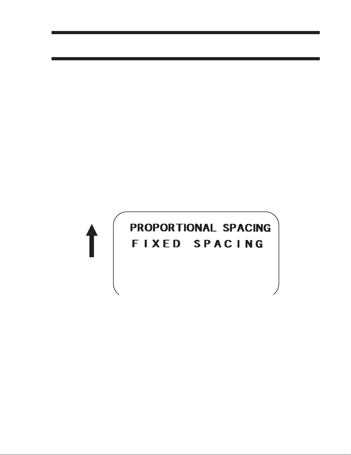
Character, Fixed Spacing
Command Structure <ESC>PR
Example: See Above
Placement: Preceding the data
Default: The default is Proportional Spacing.
Command Function To reset proportional spacing and place the printer back to fixed
spacing.
Printer Input
Printer Output
Special Notes 1. This command only works with the proportionally spaced fonts XU,
<ESC>A
<ESC>H0100<ESC>V0050<ESC>PS
<ESC>L0404<ESC>XMPROPORTIONALSPACING
<ESC>H0100<ESC>V0180<ESC>PR
<ESC>L0404<ESC>XMFIXED SPACING
<ESC>Q1<ESC>Z
XM, XS, XL and XB.
SATOCX200PrintersPN9001055 Rev. EPage 25
Page 30
CX200 Programming Guide
Character Pitch
Command Structure <ESC>Paa
aa = Number of dots between characters (00-99)
Example: <ESC>P03
Placement: Preceding the text to be printed
Default: <ESC>P02
Command Function To designate the amount of spacing (in dots) between characters.
This command provides a means of altering character spacing for
label constraints or to enhance readability.
Input to Printer:
Printer Output:
<ESC>A
<ESC>A<ESC>H0025<ESC>V0025<ESC>L0202<ESC>XB1SATO
<ESC>H0025<ESC>V0125<ESC>L0202<ESC>P20<ESC>XB1SATO
<ESC>H0025<ESC>V0225<ESC>L0202<ESC>P40<ESC>XB1SATO
<ESC>Q1<ESC>Z
Page 26PN9001055 Rev. ESATOCX200Printers
Page 31

CX200 Programming Guide
Special Notes 1. This command is affected by the <ESC>L Character Expansion
command (see Page 23). The character pitch is actually the
product of the current horizontal expansion multiple and the
designated pitch value.
Example:
<ESC>L0304
<ESC>P03
Pitch = (03) x (03) = 9 dots
2. To avoid confusion, you may want to include the <ESC>L
Character Expansion command and this command together in
your program.
3. This command affects fonts U, S, M, XU, XS, XM, OA & OB (see
Page 34) and fonts WB, WL, XB and XL (see Page 36)
4. Character Pitch will always revert to the default value unless it is
specified before each new font command in the data stream.
5. This command also affects Codabar and Code 39 bar codes.
SATOCX200PrintersPN9001055 Rev. EPage 27
Page 32

CX200 Programming Guide
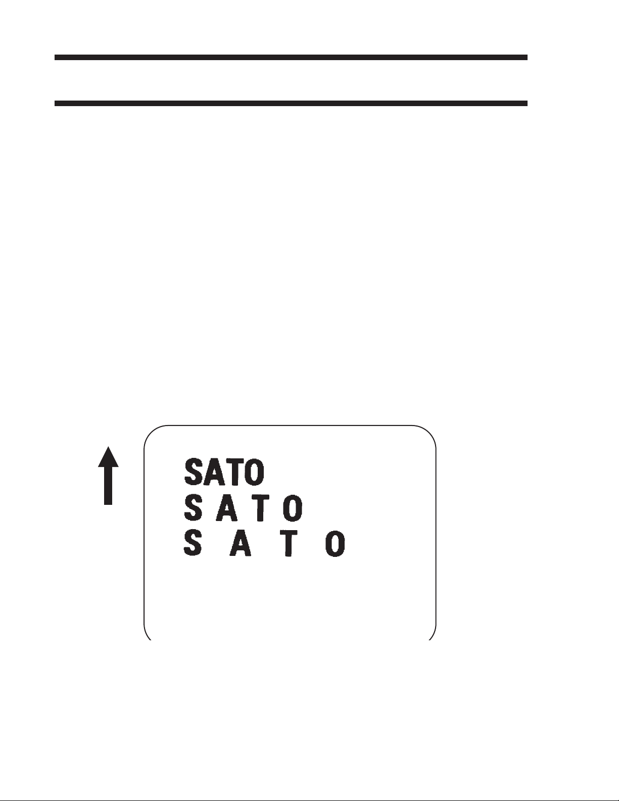
Character, Proportional Spacing
Command Structure <ESC>PS Set to proportional spacing
<ESC>PR Reset to fixed spacing
Example: See above
Placement: Preceding the data to be proportional spaced
Default: <ESC>PS
Command Function To specify the printing of proportional or fixed spacing for
proportionally spaced fonts.
Printer Input
Printer Output
Special Notes 1. Once this command is sent in the data stream, it is in effect until the
<ESC>A
<ESC>H0025<ESC>V0050<ESC>PS
<ESC>L0202<ESC>XMPROPORTIONALSPACING
<ESC>H0025<ESC>V0130<ESC>PR
<ESC>L0202<ESC>XMFIXED SPACING
<ESC>Q1<ESC>Z
end of the print job unless a reset command is sent.
Page 28PN9001055 Rev. ESATOCX200Printers
Page 33

Clear Print Job(s) & Memory
Command Structure <ESC>*a
a = Specifies the internal memory section to be cleared
Example: <ESC>*
Placement: This command should be sent to the printer as an
Default: None
CX200 Programming Guide
T To clear the custom character memory
& To clear the form overlay memory
X To clear all internal memory
<ESC>*&
independent data stream.
Command Function To clear individual memory or buffer areas of the printer.
Input to Printer:
Printer Output: There is no printer output as a result of this command. The current
Special Note 1. It is not necessary to clear the printer’s memory between each print
<ESC>A
<ESC>*
<ESC>Z
print job in the buffer will be terminated and all other print jobs in the
buffer cleared.
job.
2. When the “a” parameter is used, the section of memory specified
will not be cleared until the label is printed.
3. When the “a” parameter is not included, all sections of memory will
be cleares (same as <ES>*X).
SATOCX200PrintersPN9001055 Rev. EPage 29
Page 34

CX200 Programming Guide
Continuous Forms Printing
Command Structure None
The printer locates the end of an adhesive label by sensing the
backing between labels or through the use of an Eye-Mark (black
rectangle on the reverse side of the backing). It locates the end of a
tag from a notch, eye-mark, or a hole between tags. Both sensors
should be disabled when printing continuous forms by sending the
<ESC>CI0 command to disable the sensor (See Page 93).
If you will be using continuous labels or tags, the printer must be told
to stop feeding in another manner. The length is determined by the
position of the last printed image on the label or tag. The printer will
stop feeding when this last field is finished printing. The length may
be increased with printed spaces (20 hexadecimal) if necessary.
There is no command code to control label length.
Page 30PN9001055 Rev. ESATOCX200Printers
Page 35

Copy Image Area
Command Structure <ESC>WDHaaaaVbbbbXccccYdddd
aaaa = Horizontal position of the top left corner of the area to be copied
0001 to 832
bbbb = Vertical position of the top left corner of the area to be copied
0001 to 1424
cccc = Horizontal length of the image area to be copied
0001 to 0832
dddd = Vertical length of the image area to be copied
0001 to 1424
Example: <ESC>WDH0100V0050X0600Y0400
Placement: Anywhere within the data stream, after specifying the
location of the duplicate image.
CX200 Programming Guide
Default: None
Command Function To copy an image from one location to another on the same label.
This may be useful for duplicating individual fields or entire sections
of the label with only one command.
Input to Printer:
<ESC>A
<ESC>H0050<ESC>V0050<ESC>E010<ESC>XM
SATOSATOSATOSATOSATOSATOSATO
SATOSATOSATOSATOSATOSATOSATO
SATOSATOSATOSATOSATOSATOSATO
SATOSATOSATOSATOSATOSATOSATO
<ESC>H0180<ESC>V0250<ESC>WDH0130V0050X0400Y0200
<ESC>Q1<ESC>Z
Printer Output:
SATOCX200PrintersPN9001055 Rev. EPage 31
Page 36

CX200 Programming Guide
Special Notes 1. Use the Print Position commands (V and H) to locate the new area
for the duplicate image (see Page 53).
2. Position of the new target area must not be inside the original
image.
3. If you use the Rotate command, V, H, X and Y axis will be reversed.
4. If the reference area of the target image exceeds the print area, it
will not be printed.
Page 32PN9001055 Rev. ESATOCX200Printers
Page 37

CX200 Programming Guide
CutterCommand
Command Structure <ESC>~aaaa or <ESC><NUL>aaaa
aaaa = Number of labels to print between each cut (0001 to 9999)
Example: <ES>~0002
Placement: Fllowing the <ESC>Q Print Quantity command
Default: Cut after each label if cutter installed
Command Function To control the cutting of labels when using a SATO cutter unit with
the printer. This command allows the cutting of multi-part tags or
labels at a specified interval within a print job.
Input to Printer
Printer Output This set of commands will print 6 labels, with 2 labels betweencuts.
Special Notes 1. You must have the optional printer Cutter installed to use this
<ESC>A
<ESC>H020<ESC>V020<ESC>WB1TESTLABEL
<ESC>Q3
<ESC>~002
<ESC>Z
function. Contact your SATO representative for more information
2. To use this command, you must have the cutter enabled.
3. If the cut value is set at aaaa = 0000, the cutter is inactive.
4. When using the Cuttter command, the total number of labels printed
is the product of the cut value times the print quantity. For
example, if the cut value is 2 and the print quantity is 20, then 40
(20 sets of 2) labels will be printed.
5. Sending a Cutter command to a printer without a cutter installed will
enable the Backfeed operation.
SATOCX200PrintersPN9001055 Rev. EPage 33
Page 38

CX200 Programming Guide
Fonts U, S, M, OA, OB, XU, XS & XM
Command Structure Font XU: <ESC>XU Font U: <ESC>U
Font XS: <ESC>XS Font S: <ESC>S
Font XM: <ESC>XM Font M: <ESC>M
Font OA: <ESC>OA Font OB: <ESC>OB
Example: See above
Placement: Preceding the data to be printed
Default: None
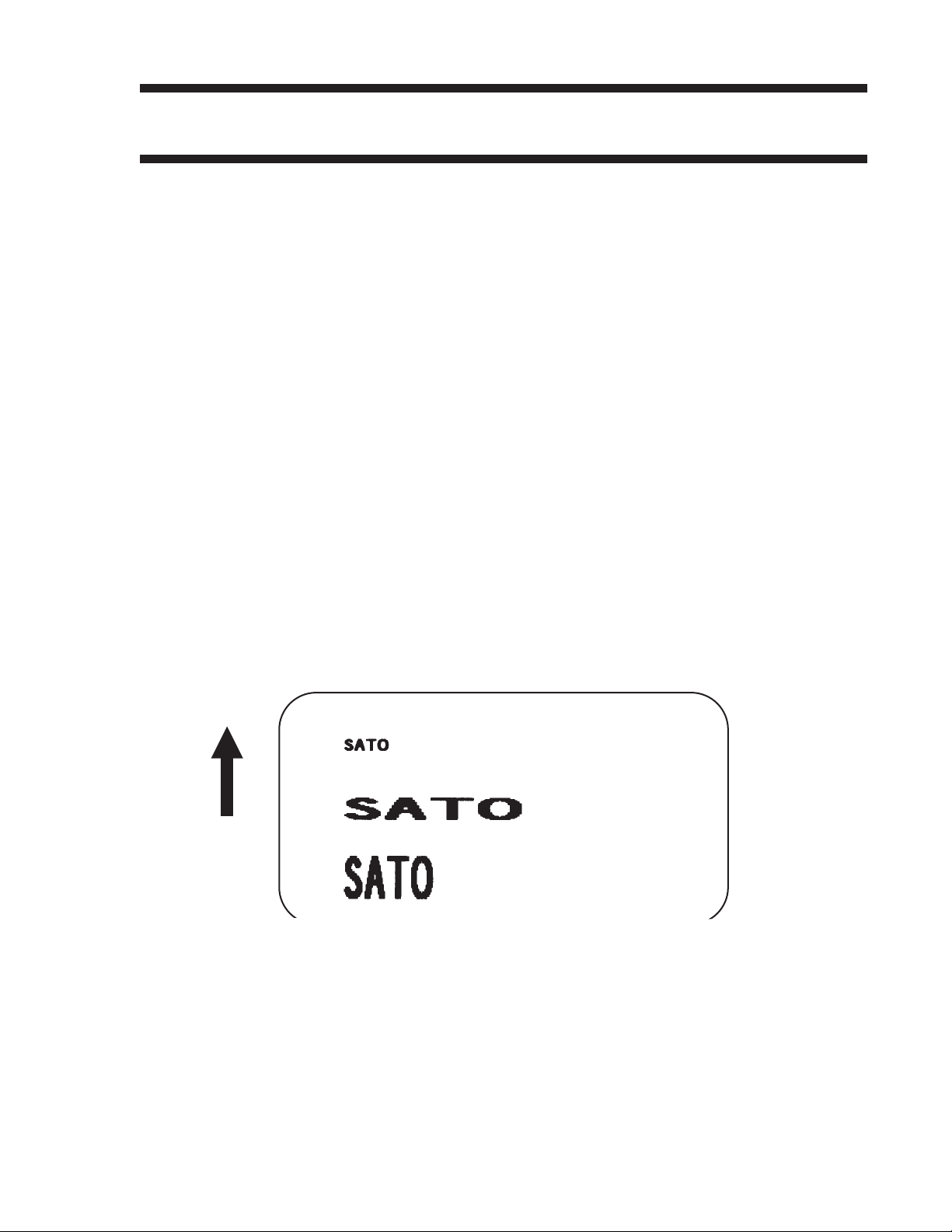
Command Function To print text images on a label. These are eight of the built-in fonts
available on the printer. All matrices include descenders.
Input to Printer
Printer Output
NON-PROPORTIONAL PROPORTIONAL
U 5W x 9H dot matrix XU 5W x 9H dot matrix
S 8W x 15H dot matrix XS 17W x 17H dot matrix
M 13W x 20H dot matrix XM 24W x 24H dot matrix
OA OCR-A font 15W x 22H
OB OCR-B font 20W x 24H
(1) These fonts will be printed with proportional spacing only if preceded by an
<ESC>PS command.
<ESC>A<ESC>PS
<ESC>H0001<ESC>V0100<ESC>L0202<ESC>XUSATO
<ESC>H0001<ESC>V0175<ESC>L0202<ESC>XSSATO
<ESC>H0001<ESC>V0250<ESC>L0202<ESC>XMSATO
<ESC>H0001<ESC>V0325<ESC>L0101<ESC>OASATO
<ESC>H0001<ESC>V0400<ESC>L0101<ESC>OBSATO
<ESC>H0300<ESC>V0100<ESC>L0202<ESC>USATO\
<ESC>H0300<ESC>V0175<ESC>L0202<ESC>SSATO
<ESC>H0300<ESC>V0250<ESC>L0202<ESC>MSATO
<ESC>Q1<ESC>Z
(1)
Page 34PN9001055 Rev. ESATOCX200Printers
Page 39

CX200 Programming Guide
Special Notes 1. Characters may be enlarged through the use of the Character
Expansion command (see Page 23).
2. Character spacing may be altered through the use of the Character
Pitch command (see Page 26). The default is 2 dots between
characters. It is recommended to use a spacing of 5 dots for
OCR-A and 1 dot for OCR-B.
3. You may also create custom characters or fonts. See the <ESC>T
Custom-Designed Characters command (Page 21).
4. A font must be defined for each field to be printed. There is no
default font.
5. The proportionally spaced fonts XU, XS, XM, XL and XA can be
printed with fixed spacing using the <ESC>PS Proportional Space
command.
SATOCX200PrintersPN9001055 Rev. EPage 35
Page 40

CX200 Programming Guide
Fonts WB, WL, XB & XL
Command Structure Font WB: <ESC>WBa Font XB: <ESC>XBa
Font WL: <ESC>WLa Font XL: <ESC>XLa
a = Provided for compatibility with CL Printers.
Can be either a 0 or a 1
Example: <ESC>WB1123456
Placement: Preceding the data to be printed
Default: None
Command Function To print text images on a label. These are the four auto-smoothing
fonts available on the printer.
NON-PROPORTIONAL PROPORTIONAL
WB 18W x 30H dot matrix XB 48W x 48H dot matrix
WL 28W x 52H dot matrix XL 48W x 48H dot matrix
(1) These fonts will be printed with proportional spacing only if preceded by an
<ESC>PS command.
Input to Printer: <ESC>A<ESC>PS
<ESC>H0001<ESC>V0100<ESC>WB0SATO
<ESC>H0001<ESC>V0185<ESC>WB1SATO
<ESC>H0001<ESC>V0270<ESC>WL0SATO
<ESC>H0001<ESC>V0355<ESC>WL1SATO
<ESC>H0300<ESC>V0100<ESC>XB0SATO
<ESC>H0300<ESC>V0185<ESC>XB1SATO
<ESC>H0300<ESC>V0270<ESC>XL0SATO
<ESC>H0300<ESC>V0355<ESC>XL1SATO
<ESC>Q1<ESC>Z
Printer Output:
(1)
Page 36PN9001055 Rev. ESATOCX200Printers
Page 41

CX200 Programming Guide
Special Notes 1. Characters may be enlarged through the use of the <ESC>L
Character Expansion command (see Page 23).
2. Character spacing may be altered through the use of the <ESC>A
Character Pitch command (see Page 26).
3. A font must be defined for each field to be printed. There is no
default font.
4. The proportionally spaced fonts XU, XS, XM, XL and XB can be
printed with fixed spacing using the <ESC>PS Proportional Space
command.
SATOCX200PrintersPN9001055 Rev. EPage 37
Page 42

CX200 Programming Guide
Form Feed
Command Structure <ESC>A(space)<ESC>Z
Example: See above
Placement: Separate data stream sent to printer
Default: None
Command Function To feed a blank tag or label, which is the equivalent of a “form feed”
Input to Printer
Printer Output Blank label or tag
<ESC>A(space)
<ESC>Z
Page 38PN9001055 Rev. ESATOCX200Printers
Page 43

CX200 Programming Guide
Form Overlay, Recall
Command Structure <ESC>/
Example: See above
Placement: Must be preceded by all other data and placed just before
the Print Quantity command (<ESC>Q)
Default: None
Command Function To recall the label image from the form overlay memory for printing.
This command recalls a stored image from the overlay memory.
Additional or different data can be printed with the recalled image.
Input to Printer
Printer Output
<ESC>A
<ESC>H01000<ESC>V0125
<ESC>STHIS IS THE STORED IMAGE WITH A BARCODE
<ESC>H0100<ESC>V0165<ESC>B103100*12345*
<ESC>&<ESC>Z
<ESC>A<ESC>H0100<ESC>V0050
<ESC>STHIS IS RECALLING AND ADDING TO THE STORED IMAGE<ESC>/
<ESC>Q1<ESC>Z
Special Notes 1. The overlay is stored using the <ESC>& Form Overlay Store
command (see Page 40).
2. The <ESC>AX Expanded Print Length command (see Page 51)
cannot be used with Forms Overlay.
SATOCX200PrintersPN9001055 Rev. EPage 39
Page 44

CX200 Programming Guide
Form Overlay, Store
Command Structure <ESC>&
Example: See above
Placement: Must be preceded by all other data and placed just before
the Stop command (<ESC>Z)
Default: None
Command Function To store a label image in the volatile form overlay memory. Only one
label image may be stored in this memory area at a time.
Input to Printer
<ESC>A
<ESC>H0100<ESC>V0125
<ESC>STHIS IS THE STORED IMAGE WITH A BARCODE
<ESC>H0100<ESC>V0165<ESC>B103100*12345*
<ESC>&
<ESC>Z
Printer Output There is no output from this command. It stores the label image in the
overlay buffer.
Special Notes 1. Remember that this storage is volatile. Therefore, if the printer
loses power, the overlay must be sent again.
2. The overlay is recalled using the <ESC>/ Form Overlay Recall
command (see Page 39).
3. Form overlays do not have to be recompiled each time they are
called to be printed and therefore may result in much faster print
output.
4. The Expanded Print Length <ESC>AX (see Page 51) cannot be
used with this command. The maximum length label that can be
used with Forms Overlay is 7".
Page 40PN9001055 Rev. ESATOCX200Printers
Page 45

Graphics, Custom
Command Structure <ESC>Gabbbccc(data)
a = Specifies format of data stream to follow
B Binary format
H Hexadecimal format
bbb = Number of horizontal 8 x 8 blocks
001 to 104
ccc = Number of vertical 8 x 8 blocks
001 to 178 (001 to 356 for Expanded Length)
(data)= Hex data to describe the graphic image
CX200 Programming Guide
Example: <ESC>GH006006
See Appendix C for a detailed example
Placement: May be placed anywhere within the data stream after the
necessary position commands.
Default: None
Command Function To create and print custom graphics (logos, pictures, etc.) on a label.
The graphic image may be printed along with other printed data to
enhance label appearance or eliminate the need for preprinted label
stock. Using a dot-addressable matrix, design the graphic image in 8
dot by 8 dot blocks, then send it in a binary format to the printer.
Printer Input
<ESC>A
<ESC>H0100<ESC>V0100<ESC>GH006006
FFFFFFFFFFFFFFFFFFFFFFFFC00000000003
C00000000003C000FFFFFFF3C00080000013
C00080000013C0009FFFFF13C00080000013
C00080000013C0009FFFFF13C00080000013
C00080000013C000FFFFFFF3C00000000003
C00000000003C00000000003C00000000003
C00000000003C00000000003C00003C00003
C00007E00003C0000FF00003C0000FF00003
C0000FF00003C0000FF00003C00007E00003
C00003C00003C00003C00003C00003C00003
C00003C00003C00003C00003C00003C00003
C00003C00003C00003C00003C00003C00003
C00003C00003C00001800003C00000000003
C00000000003FFFFFFFFFFFFFFFFFFFFFFFF
<ESC>H0300<ESC>V0100<ESC>XSPLEASE PLACEYOUR DISK
<ESC>H0300<ESC>V0150<ESC>XSIN A SAFE PLACE
<ESC>Q1<ESC>Z
SATOCX200PrintersPN9001055 Rev. EPage 41
Page 46

CX200 Programming Guide
Printer Output
Special Notes 1. Do not use ASCII <CR> or <LF> characters (carriage return or line
feed) as line delimiters within the graphic data or the actual image
will not be printed as specified.
2. A custom graphic cannot be enlarged by the <ESC>L Character
Expansion command (Page 23).
3. A custom graphic is not affected by either of the Rotation
commands. Therefore, always design and locate your graphic
image to print in the appropriate orientation.
4. The binary format reduces the transmission time by 50%.
Page 42PN9001055 Rev. ESATOCX200Printers
Page 47

CX200 Programming Guide
Graphics, PCX
Command Structure <ESC>GPaaaaa,(data)
aaaaa = Number of bytes to be downloaded
Example: <ESC>GP32000, ... data...
Placement: Anywhere within the job data stream
Default: None
Command Function To allow the creation and printing of graphic images using a PCX file
format.
Printer Input See Appendix Appendix C for a detailed example
<ESC>A
<ESC>V0150<ESC>H0100<ESC>GP03800,(...Data...)
<ESC>Q1
<ESC>Z
Printer Output
Special Notes 1. The maximum number of bytes that can be downloaded is 32K
(compressed). The number specified by this command includes
the PCX header information. The maximum size of the
uncompressed PCX file is 64K. If the uncompressed file exceeds
64K, the graphic will not print.
2. Only black and white PCX files can be downloaded.
3. The image created by this command cannot be rotated.
4. The file size specified by this command is the DOS file size in bytes.
SATOCX200PrintersPN9001055 Rev. EPage 43
Page 48

CX200 Programming Guide
Journal Print
Command Structure <ESC>J
Example: See above
Placement: Immediately following <ESC>A
Default: None
Command Function To print text in a line by line format on a label. By specifying this
command, you automatically select Font S with a Character
Expansion of 2x2. You also establish a base reference point of
H2,V2. The character pitch is 2 dots and the line gap is 16 dots.
Simply issue an ASCII <CR> at the end of each text line.
Input to Printer
Printer Output
Special Notes 1. Journal mode assumes a maximum label width. Otherwise, you
<ESC>A
<ESC>J WITH THE JOURNAL FEATURE
YOU CAN PRINT TEXT WITHOUT
USING ANY FONT COMMANDS
OR POSITION COMMANDS
<ESC>Q1<ESC>Z
may print where there is no label and damage your print head.
2. It is effective only for the current print job.
Page 44PN9001055 Rev. ESATOCX200Printers
Page 49

Lines and Boxes
Command Structure Line <ESC>FWaabcccc
aa = Width of horizontal line in dots (01-99)
b = Line orientation
H Horizontal line
V Vertical Line
cccc = Length of line in dots (see Note 2 for max length)
Box: <ESC>FWaabbVccccHdddd
aa = Width of horizontal side in dots (01-99)
CX200 Programming Guide
bb = Width of vertical side in dots (01-99)
cccc = Length of vertical side in dots (0001 to 1424)
dddd = Length of horizontal side in dots (0001 to 0832)
Example: <ESC>FW02H0200
Placement: Following the necessary positioning commands
Default: None
Command Function To print horizontal lines, vertical lines, and boxes as images on the
label.
Input to Printer
<ESC>A
<ESC>H0100<ESC>V0100<ESC>FW20H0200
<ESC>H0320<ESC>V0100<ESC>FW20V0200
<ESC>H0350<ESC>V0100<ESC>FW1010H0200V0200
<ESC>Q1<ESC>Z
SATOCX200PrintersPN9001055 Rev. EPage 45
Page 50

CX200 Programming Guide
Printer Output
Special Notes 1. It is recommended that all lines and boxes be specified in the
normal print direction.
Page 46PN9001055 Rev. ESATOCX200Printers
Page 51

CX200 Programming Guide
Line Feed
Command Structure <ESC>Eaaa
aaa = Number of dots (001-999) between the bottom of the
characters on one line to the top of the characters on
the next line
Example: <ESC>E010
Placement: Preceding the text that will use the line feed function
Default: None
Command Function To print multiple lines of the same character size without specifying a
new print position for each line. With the Line Feed command, specify
the number of dots you want between each line. Then, send an ASCII
<CR> at the end of each line of text. The printer automatically
identifies the size of the last character, moves down the number of
dots specified, and begins printing the next line.
Input to Printer
Printer Output
Special Notes 1. It is effective only for the current data stream.
<ESC>A
<ESC>E010<ESC>H0050<ESC>V0050<ESC>L0202<ESC>S
THIS IS THE 1ST LINE<>CR>
THIS IS THE 2ND LINE>CR>
THIS IS THE 3RD LINE>CR>
<ESC>Q1<ESC>Z
2. When printing lines or boxes in the same data stream with the Line
Feed command, the Lines and Boxes command should be
specified last, preceding <ESC>Q Quantity command.
3. This command is invalid only if the value specified is zero.
4. Following this command with a <CR> character will allow you to
print with auto line feed. Tthe print position will be determined
from the value specified and the H value set in the printer. If you
specify several H values after this command, the print position will
be determined by the H value last specified. You must redefine
the font to be used after each H command.
SATOCX200PrintersPN9001055 Rev. EPage 47
Page 52

CX200 Programming Guide
Off-Line/Pause
Command Structure <ESC>@
Example: See above
Placement: Anywhere in the print job between the <ESC>A and
<ESC>Z
Default: None
Command Function To specify the printer to come to an off-line state. When used within a
print job, the printer goes off-line after finishing the print job.
Input to Printer
Printer Output There is no printer output for this command. The printer is placed in
Special Notes 1. You must press the READY indicator key on the front panel to
<ESC>A
<ESC>@...Job...
<ESC>Z
the Off-Line mode as soon as the current print job is finished.
return the printer to an On-Line status .
2. Remember, when using this command, that the print job specifies
<ESC>Q10, all ten labels will print before the printer goes off-line.
3. This command will clear the print buffer.
Page 48PN9001055 Rev. ESATOCX200Printers
Page 53

Postnet
Command Structure <ESC>BPn...n
n...n = 5 digits (Postnet-32 format)
6 digits (Postnet-37 format)
9 digits (Postnet-52 format)
11 digits (Postnet-62, Delivery Point format)
Example: <ESC>BP123456789
Placement: Immediately preceding the data to be encoded
Default: None
Command Function To print Postnet bar codes
CX200 Programming Guide
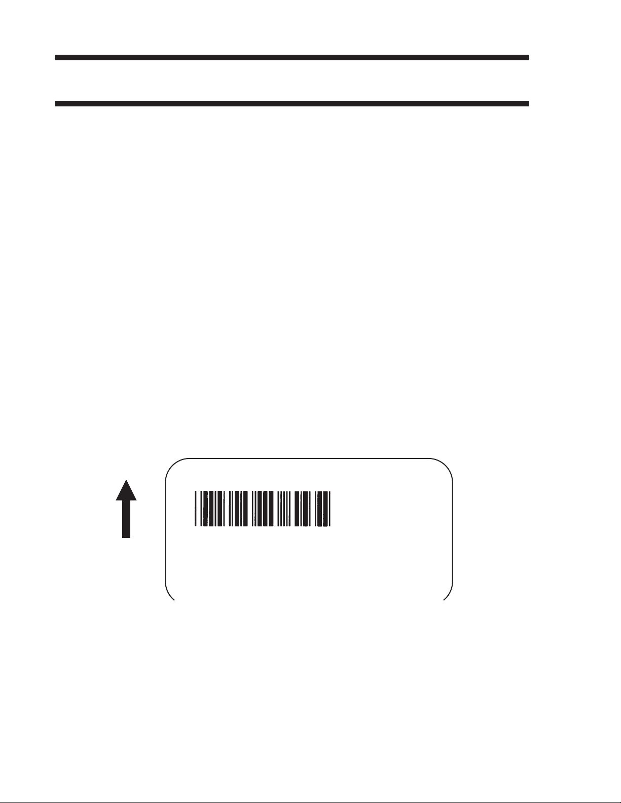
Printer Input
Printer Output
Special Notes 1. If the number of data digits does not match the Postnet formats
<ESC>A
<ESC>H0100<ESC>V0120<ESC>BP94089
<ESC>H0100<ESC>V0160<ESC>BP123456
<ESC>H0100<ESC>V0200<ESC>BP123456789
<ESC>H0100<ESC>V0240<ESC>BP12345678901
<ESC>Q1<ESC>Z
listed, the command is ignored.
2. Only numeric data will be accepted.
SATOCX200PrintersPN9001055 Rev. EPage 49
Page 54

CX200 Programming Guide
Print Darkness
Command Structure <ESC>#Ea
a = Print darkness value
a = 1, 2, 3, 4 or 5
Example: <ESC>#E2
Placement: Must be placed immediately after <ESC>A and
immediately before <ESC>Z in its own separate data stream
Default: 2
Command Function To specify a new print darkness setting. This command allows
software control of the darkness setting for unique media and ribbon
combinations.
Input to Printer
Printer Output There is no printer output for this command.
Special Notes 1. This becomes the new setting in the printer configuration for all
<ESC>A
<ESC>#E2
<ESC>Z
subsequent print jobs, unless changed. The setting is stored in
non-volatile memory and is not affected by cycling power.
2. The lighest setting is the smallest value and the darkest setting is
the largest value.
3. This command adjusts the print darkness in discrete steps. The
range of this command is set using the <ESC>CD Print Darkness
Fine Adjustment command (Page 90). Changing the Print
Darkness Fine Adjustment setting will affect this command.
Page 50PN9001055 Rev. ESATOCX200Printers
Page 55

CX200 Programming Guide
Print Length, Expanded
Command Structure <ESC>AX Sets the print length to 14" (356 mm)
<ESC>AR Resets the maximum print length to 7" (178 mm)
Example: See above
Placement: Must follow the Start Code command (see Page 68)
and be in it’s own separate data stream.
Default: <ESC>AR
Command Function To double the maximum print length (in feed direction) for a label.
Input to Printer:
Printer Output:
<ESC>A
<ESC>AX
<ESC>Z
<ESC>A
<ESC>H0050<ESC>V0100<ESC>WB1EXPAND TO:
<ESC>H0050<ESC>V2700<ESC>WB114 INCHES
<ESC>Q1<ESC>Z
<ESC>A
<ESC>AR
<ESC>Z
14"
SATOCX200PrintersPN9001055 Rev. EPage 51
Page 56

CX200 Programming Guide
Special Notes 1. AX is effective until AR is sent to reset the printer to its standard
print length, or until the printer is repowered.
2. It may be included in an independent data stream to specify the
size of the maximum print area:
3. This command is cannot be used with the <ESC>& Store Form
Overlay command (see Page 40).
Page 52PN9001055 Rev. ESATOCX200Printers
Page 57

Print Position
Command Structure Horizontal Position: <ESC>Haaaa
Vertical Position: <ESC>Vbbbb
aaaa = Number of dots horizontally from the base reference point
0001 to 0832.
bbbb = Number of dots vertically from the base reference point
0001 to 1424 (0001 to 2848 with Expanded Print Length).
Example: <ESC>H0020<ESC>V0150
Placement: Preceding any printed field description of lines/boxes,
fonts, bar codes or graphics.
CX200 Programming Guide
Default: <ESC>H0001
<ESC>V0001
Command Function The Horizontal and Vertical commands specify the top left corner of a
field or label, using the current base reference point as an origin.
They also establish a reference point for subsequent fields until the
next horizontal and/or vertical print position command is issued.
Input to Printer
Printer Output
<ESC>A
<ESC>H0025<ESC>V0050<ESC>L0303<ESC>MSATO
<ESC>H0100<ESC>V0150<ESC>MSATO
<ESC>Q2<ESC>Z
Special Notes 1. The print position of a field is affected by both the Rotate (<ESC>R
and <ESC>A3) commands.
SATOCX200PrintersPN9001055 Rev. EPage 53
Page 58

CX200 Programming Guide
2. If any part of an image is placed past the maximum number of dots
3. If any part of an image is placed past maximum allowable dots
4. If you attempt to print where there is no paper, you may damage
5. For these commands, the leading zeroes do not have to be
for standard length.
across the label, that part of the image will be lost.
the print head.
entered. The command V1 is equivalent to V0001.
Page 54PN9001055 Rev. ESATOCX200Printers
Page 59

CX200 Programming Guide
Print Quantity
Command Structure <ESC>Qaaaaaa
aaaaaa = Total number of labels to print (1 to 65535)
Example: <ESC>Q500
Placement: Just preceding <ESC>Z, unless <ESC>~ Cutter
command exists, then preceding that. This command
must be present in every print job.
Default: None
Command Function To specify the total number of labels to print for a given print job.
Input to Printer
Printer Output Three labels containing the data “SATO” wll be printed.
Special Notes 1. To cancel a print job, you must turn off the printer.
<ESC>A
<ESC>H0100<ESC>V0100<ESC>WB1SATO
<ESC>Q3
<ESC>Z
3. When used with the <ESC>F Sequential Numbering command (see
Page 66, the Print Quantity value should be equal to the total
number of labels to be printed.
4. If you do not specify a Print Quantity, the printer will not print a label.
5. For this command, leading zeroes do not have to be entered. The
command Q1 is equivalent to Q000001.
SATOCX200PrintersPN9001055 Rev. EPage 55
Page 60

CX200 Programming Guide
Print Speed
Command Structure <ESC>CSa
a = Designates the speed selection
2 = 2 ips (50 mm/s)
3 = 3 ips (75 mm/s)
Example: <ESC>CS3
Placement: Must be placed immediately after <ESC>A and
immediately before <ESC>Z in its own separate data stream
Default: As previously set in the printer configuration
Command Function To specify a unique print speed through software for a particular
label. This allows flexibility in finding the best performance and quality
for the particular label format, media, and ribbon. All subsequent
labels will print at this speed unless the speed is changed with this
command.
Input to Printer
Printer Output There is no printer output for this command. It sets the print speed of
Special Notes 1. This becomes the new setting in the printer configuration for all
<ESC>A
<ESC>CS3
<ESC>Z
the printer to 3 iinches per second..
subsequent print jobs, unless changed. The setting is stored in
non-volatile memory and is not affected by cycling the power.
Page 56PN9001055 Rev. ESATOCX200Printers
Page 61

Repeat Label
Command Structure <ESC>C
Example: See above
Placement: Must be placed immediately after <ESC>A and
immediately before <ESC>Z in its own separate data stream
Default: None
Command Function To print duplicate of the last label printed
CX200 Programming Guide
Input to Printer
Printer Output A duplicate of the previous label will be printed.
Special Notes 1. This command will have no effect if the power to the printer was
<ESC>A
<ESC>C
<ESC>Z
cycled off and back on since printing the previous label.
SATOCX200PrintersPN9001055 Rev. EPage 57
Page 62

CX200 Programming Guide
Replace Data (Partial Edit)
Command Structure <ESC>0 (<ESC>zero)
Example: See above
Placement: Must follow <ESC>A and precede all other print data
Default: None
Command Function To replace a specified area of the previous label with new data. This
command will cause the previous label to print along with any
changes specified within the current data stream.
Input to Printer
Printer Output
<ESC>A
<ESC>H0025<ESC>V0020<ESC>WB0CompanyName
<ESC>H0025<ESC>V0085<ESC>WB1SATO
<ESC>H0025<ESC>V0150<ESC>WL0SATO
<ESC>H0025<ESC>V0215<ESC>WL1SATO
<ESC>Q1<ESC>Z
<ESC>A
<ESC>0<ESC>H0025<ESC>V0020<ESC>WB0SATO
<ESC>Q1<ESC>Z
Page 58PN9001055 Rev. ESATOCX200Printers
Page 63

CX200 Programming Guide
Special Notes 1. Specify the exact same parameters for the image to be replaced as
were specified in the original data stream, including rotation,
expansion, pitch, etc. This will ensure that the new data will
exactly replace the old image. If the replacement data contains
fewer characters than the old data, then the characters not
replaced will still be printed.
2. This command will not function if the power has been cycled off and
back on since the last label was printed.
3. Proportional Pitch text cannot be used with this command.
SATOCX200PrintersPN9001055 Rev. EPage 59
Page 64

CX200 Programming Guide
Reverse Image
Command Structure <ESC>(aaaa,bbbb
a = Horizontal length in dots of reverse image area
0000 to 0832
b = Vertical height in dots of reverse image area.
0000 to 1424
Example: <ESC>(100,50
Placement: This command must be preceded by all other data and be
placed just before <ESC>Q
Default: None
Command Function To reverse an image area from black to white and vice versa. Use the
Print Position commands (<ESC>H and <ESC>V) to locate the top
left corner of the reverse image area.
Input to Printer
Printer Output
<ESC>A
<ESC>H0050<ESC>V0120<ESC>L0202<ESC>WB1REVERSE
<ESC>H0250<ESC>V0300<ES C>L0202<ESC>WB1HALF
<ESC>H0040<ESC>V0110<ESC>(370,100
<ESC>H0240<ESC>V0290<ESC>(220,47
<ESC>Q1<ESC>Z
Page 60PN9001055 Rev. ESATOCX200Printers
Page 65

CX200 Programming Guide
Special Notes 1. A reverse image area is affected by the rotate commands.
Therefore, always assume the printer is in the normal print
orientation when designing and sending the Reverse Image
command.
2. If using reverse images with the form overlay, place this command
before the Form Overlay command in the data stream.
3. If the Rotate commands are used with this command, the V and H
parameters are reversed.
4. If the height and width to be reversed contain other than
alphanumeric data, the area is not printed.
5. If the values specified exceed the maximum ranges, the reverse
image is not created.
SATOCX200PrintersPN9001055 Rev. EPage 61
Page 66

CX200 Programming Guide
Rotate, Fixed Base Reference Point
Command Structure <ESC>%a
a = 0 Sets print to normal direction
1 Sets print to 90°CCW
2 Sets print to 180° rotated (upside down)
3 Sets print to 270° CCW
Example: <ESC>%3
Placement: Preceding any printed data to be rotated
Default: <ESC>%0
Command Function To rotate the print direction in 90° increments without changing the
location of the base reference point. The diagram below illustrates the
use of the <ESC>% Rotate command. Note that the entire print area
is shown, but your label will probably not be as large as the entire
area.
Input to Printer
Printer Output
<ESC>A
<ESC>%0<ESC>L202<ESC>H0200<ESC>V0100<ESC>MNORMAL DIRECTION
<ESC>%1<ESC>H0200<ESC>V0300<ESC>MONE
<ESC>%2<ESC>H0200<ESC>V0400<ESC>MTWO
<ESC>%3<ESC H0200<ESC>V0500<ESC>MTHREE
<ESC>Q1<ESC>Z
Page 62PN9001055 Rev. ESATOCX200Printers
Page 67

CX200 Programming Guide
Special Notes 1. Do not combine this command and the <ESC>R Rotate command
(see Page 64) in the same data stream.
2. The specified values are valid until another Rotate (<ESC>%)
command is received.
3. Receipt of a Stop Print (<ESC>Z) command will reset the setting to
the default value.
SATOCX200PrintersPN9001055 Rev. EPage 63
Page 68

CX200 Programming Guide
Rotate, Moving Base Reference Point
Command Structure Normal Direction: <ESC>N
Rotated Direction: <ESC>R
Example: See above
Placement: Preceding any printed data to be rotated
Default: <ESC>N
Command Function The <ESC>R command rotates the printing of all subsequent images
in a print job by 90° counterclockwise each time it is used. It also
moves the base reference point to a different corner of the print area.
The <ESC>N command returns to the original base reference point
and returns printing to the normal orientation.
Input to Printer
Printer Output
<ESC>A
<ESC>N<ESC>L202<ESC>H0100<ESC>V0010<ESC>MNORMAL DIRECTION
<ESC>R<ESC>H0100<ESC>V0100<ESC>MONE
<ESC>R<ESC>H0100<ESC>V0100<ESC>MTWO
<ESC>R<ESC>H0100<ESC>V0100<ESC>MTHREE
<ESC>R<ESC>H0100<ESC>V0100<ESC>MFOUR
<ESC>Q1<ESC>Z
Page 64PN9001055 Rev. ESATOCX200Printers
Page 69

CX200 Programming Guide
Special Notes 1. This command is provided for compatibility with other SATO
printers. It is not recommended for new label designs and the
<ESC>% rotate command should be used.
2. Do not combine this command and the <ESC>% rotate command
(see Page 62) in the same data stream.
3. A custom graphic is not affected by this command. Therefore,
always design and locate your graphic image to print in the
appropriate orientation.
4. See Rotated Fields, Page 7, for more information.
5. The specified values are valid until another Rotate (<ESC>R)
command is received.
6. Receipt of a Stop Print (<ESC>Z) command will reset the setting to
the default value.
SATOCX200PrintersPN9001055 Rev. EPage 65
Page 70

CX200 Programming Guide
Sequential Numbering
Command Structure <ESC>Faaaabcccc,dd,ee
aaaa = Number of times to repeat the same data (0001-9999)
b = Plus or minus symbol (+ for increments; - for decrements)
cccc = Value of step for sequence (0001-9999)
,dd = Number of digits for sequential numbering (01-99). The first
incrementing character position starts after the positions
exempted from sequential numbering as specified in ee.
If these digits are left out, the default is 8.
,ee = Number of digits free from sequential numbering (00-99)
starting with the right most position. If these digits are left out,
the default is 0.
Example: <ESC>F001-001,04,03
Decrementing
4321321
00
Free from Decrementing
In this example, the right most (least significant) three digits
would not decrement and the next four would decrement.
Placement: Preceding the starting value to be incremented or
decremented.
Default: None
Command Function To allow the ability to print sequential fields (text, bar codes) where all
incrementing is done within the printer. Up to eight different
sequential fields can be specified per label. Sequencing is effective
for up to 99-digit numeric data within each field.
Input to Printer
<ESC>A<ESC>H0100<ESC>V0100<ESC>MSERIALNUMBER:
<ESC>H0100<ESC>V0200<ESC>F001+005
<ESC>L0202<ESC>M1000
<ESC>Q2<ESC>Z
Page 66PN9001055 Rev. ESATOCX200Printers
Page 71

Printer Output
CX200 Programming Guide
Special Notes 1. The value specified for Print Quantity (see Page 55) should be
equal to the number of different sequential values desired
multiplied by the number of repeats specified.
Example:
To print 2 sets each of the numbers 1001-1025 on separate
labels, we need 50 total labels. The commands would be as
follows:
<ESC>A
<ESC>H0100<ESC>V0100<ESC>F002+001<ESC>XM1001
<ESC>Q50
<ESC>Z
2. It is necessary to specify the print position for each sequential field
on a label.
3. Up to eight different sequential fields can be specified per label.
4. This command ignores alpha characters in the sequential number
field.
5. This command can not be used with the following commands:
Copy Image, Page 31
Reverse Image, Page 60
Line Feed, Page 47
SATOCX200PrintersPN9001055 Rev. EPage 67
Page 72

CX200 Programming Guide
Start/Stop Label
Command Structure Start Command: <ESC>A
Stop Command: <ESC>Z
Example: See above
Placement: <ESC>A must precede data
<ESC>Z must follow data
Default: None
Command Function For all print jobs, the Start command must precede the data, and the
Stop command must follow. The print job will not run properly if these
are not in place.
Input to Printer
Printer Output There is not output for these commands they are not accompanied by
<ESC>A
<ESC>H0001<ESC>V0100<ESC>WB1SATO
<ESC>H0130<ESC>V0200<ESC>B103150*SATO*
<ESC>H0170<ESC>V0360<ESC>L0202<ESC>S*SATO*
<ESC>Q1<ESC>Z
other label printing commands. However, these commands must
precede and follow each print job sent to the printer.
Page 68PN9001055 Rev. ESATOCX200Printers
Page 73

Expanded Memory Option Commands
These commands require the Expanded Memory Option.
The first 2MB of Expanded Memory installed is designated as memory area CC1.
If 4MB of Expanded Memory is installed, second 2MB (i.e. the area above the first 2
MB) is designated as memory area CC2.
CX200 Programming Guide
SATOCX200PrintersPN9001055 Rev. EPage 69
Page 74

CX200 Programming Guide
Expanded Memory Function
Fonts, TrueType Recall
Command Structure <ESC>BJRabbccddeeeeff...f
a = Font ID (0 thru 9)
bb = Horizontal Expansion (01 thru 12)
cc = Vertical Expansion (01 thru 12)
dd = Character Pitch (01 thru 99)
eeee = Number of characters to be printed using the font
ffff = Data to be printed
Example: <ESC>BJR1020201000004SATO
Placement: Immediately following the <ESC>CC Memory Area Select
command.
Default: None
Command Function This command recalls previously stored TrueType fonts from
Expanded Memory.
Printer Input
Printer Output
<ESC>A
<ESC>V0100<ESC>H0100<ESC>CC1<ESC>BJR1020201000004SATO
<ESC>Q1<ESC>Z
Special Notes 1. This command requires the Expanded Memory option. See your
SATO representative for details.
Page 70PN9001055 Rev. ESATOCX200Printers
Page 75

CX200 Programming Guide
Expanded Memory Function
Fonts, TrueType Store
The conversion from a TrueType font to a format that can be downloaded to the
printer is very complex and requires the use of a TrueType Download utility
program. See your SATO representative for details. This process requires the
Expanded Memory option.
SATOCX200PrintersPN9001055 Rev. EPage 71
Page 76

CX200 Programming Guide
Expanded Memory Function
Graphics, Custom Recall
Command Structure <ESC>GRaaa
aaa = Graphics storage number (001-999)
Example: <ESC>GR111
Placement: The Recall command is sent in a secondary data stream
Default: None
to print the graphic, and follows any necessary position
or size commands.
Command Function Use the Recall command any time you want to print a graphic image
on a label along with other printed data.
Printer Input
Printer
Output
Non Rotated Graphic Graphic Rotated 90°
<ESC>A<ESC>CC1 <ESC>A<ESC>CC1<ESC>%1
<ESC>V0100<ESC>H0080<ESC>L0505 <ESC>V0180<ESC>H0250<ESC>L0505
<ESC>GR001 <ESC>GR001
<ESC>Q1<ESC>Z <ESC>Q1<ESC>Z
Graphic Rotated 180° Graphic Rotated 270°
<ESC>A<ESC>CC1<ESC>%2 <ESC>A<ESC>CC1<ESC>%3
<ESC>V0180<ESC>H0500<ESC>L0505 <ESC>V0100<ESC>H0700<ESC>L0505
<ESC>GR001 <ESC>GR001
<ESC>Q1<ESC>Z <ESC>Q1<ESC>Z
Special Notes 1. The graphic image to be stored cannot be rotated before it is
stored. It can be rotated when it is recalled.
2. Graphic images cannot be stored as part of a label format.
3. See the <ESC>GI Custom Graphic Store command.
Page 72PN9001055 Rev. ESATOCX200Printers
Page 77

Expanded Memory Function
Graphics, Custom Store
Command Structure <ESC>GIabbbcccddd{data}
a = Specifies character format of the data
H Hex data
B Binary data
bbb = Number of horizontal 8 x 8 blocks (001 to104)
ccc = Number of vertical 8 x 8 blocks (001 to178)
ddd = Graphics storage number (001 to 099)
{data}= Hex or binary data to describe the graphic image
Example: See Appendix C for detailed information on creating Hex
and Binary graphic files.
CX200 Programming Guide
Placement: Immediately following the <ESC>CC Memory Area Select
command.
Default: None
Command Function To provide similar functionality to the <ESC>G Custom Graphic
command (see Page 41), but allows for the graphic image to be
stored in a Expanded Memory. Use the Store command to send the
graphic data to the printer, which is held in the optional Expanded
Memory, even if printer power is lost.
Printer Input
Printer Output There is no printer output as a result of this command. See
Special Notes 1. You must have the optional Expanded Memory to use this
<ESC>A
<ESC>CC1<ESC>GIH002002001
0100038007C00FE01FF03FF87FFCFFFE07C007C007C007C007C007C007C007C0
<ESC>Z
Note: See Appendix C for detailedexplanation on how to format a graphics data
stream.
<ESC>GR Recall Custom Graphics command.
command. Call your SATO representative for details.
2. The maximum storage capacity is 999 graphics, up to the capacity
of the memory expansion.
3. Each graphic to be stored must be sent in its own data stream.
SATOCX200PrintersPN9001055 Rev. EPage 73
Page 78

CX200 Programming Guide
Example of correct data stream:
Example of incorrect data stream:
5. Do not use ASCII <CR> or <LF> characters (carriage return or line
6. The graphics storage number (ddd) must be specified with this
<ESC>A
<ESC>GIHaaabbb001(DATA)
<ESC>Z
<ESC>A
<ESC>GIHaaabbb002(DATA)
<ESC>Z
<ESC>A
<ESC>GIHaaabbb001(DATA)
<ESC>GIHaaabbb002(DATA)
<ESC>Z
feed) as line delimiters within the graphic data or the actual image
will not be printed as specified.
command.
Page 74PN9001055 Rev. ESATOCX200Printers
Page 79

CX200 Programming Guide
Expanded Memory Function
Graphics, PCX Recall
Command Structure <ESC>PYaaa
aa = Storage area number (001 thru 099)
Example: <ESC>PY001
Placement: This command must be placed within its own data
stream specifying the placement of the graphic.
Default: None
Command Function To recall for printing a graphic file previously stored in a PCX format
in the Memory Card.
Printer Input
Printer Output
Normal Rotation Rotate Base Reference Point
<ESC>A<ESC>CC1 <ESC>A<ESC>CC1<ESC>%1
<ESC>V0100<ESC>H0001<ESC>PY001 <ESC>V0330<ESC>H0110<ESC>PY001
<ESC>Q1<ESC>Z <ESC>Q1<ESC>Z
2nd Rotation, Base Reference Point 3rd Rotation, Base Reference Point
<ESC>A<ESC>CC1<ESC>%2 <ESC>A<ESC>CC1<ESC>%3
<ESC>V0330<ESC>H0550<ESC>PY001 <ESC>V0100<ESC>H0750<ESC>PY001
<ESC>Q1<ESC>Z <ESC>Q1<ESC>Z
Special Notes: 1. This command requires Expanded Memory option. See your SATO
representative for details.
2. See the <ESC>PI Store PCX Graphics command.
SATOCX200PrintersPN9001055 Rev. EPage 75
Page 80

CX200 Programming Guide
Expanded Memory Function
Graphics, PCX Store
Command Structure <ESC>PIaaa,bbbbb,{data}
aaa = Storage area number (001 thru 999)
bbbbb = Size of PCX file in bytes
{data} = Data
Example: <ESC>PI001,32000,{data}
Placement: This command must be placed within its own data
stream
Default: None
Command Function To store for later printing a PCX graphic file in Expanded Memory.
Printer Input BASIC Program to Download a PCX file to Expanded Memory
Section #1 (first 2MB installed).
OPEN “C:\WIZARD\GRAPHICS\LION.PCX”FOR INPUT AS #2
DA$ = INPUT$(3800,#2)
C$ = CHR$(27)
WIDTH “LPT1:”,255
LPRINT C$;"A";C$;"CC1";
LPRINT C$; “PI001,03800,”;DA$
LPRINT C$;"Z";
CLOSE #2
Printer Output There is no printer output as a result of this command. See <ESC>PY
PCX Graphics Recall command.
Special Notes: 1. This command requires Expanded Memory option. See your SATO
representative for details.
2. Graphics cannot be stored as part of a format.
3. Only black and white PCX files can be stored.
4. The file size specified by this command is the DOS file size in bytes.
Page 76PN9001055 Rev. ESATOCX200Printers
Page 81

CX200 Programming Guide
Expanded Memory Function
Initialize
Command Structure <ESC>BJFaaaaaaaa
aaaaaaa = Eight character alphanumeric user ID
Example: <ESC>BJFsato
Placement: Immediately following the <ESC>CC Memory Area
Select command.
Default: None
Command Function This clears all of the data from the specified Memory Area and
prepares the area to accept data.
Input to Printer
Printer Output There is no printer output as a result of this command.
Special Notes 1. You must have the optional Expanded Memory to use this
<ESC>A
<ESC>CC2<ESC>BJFsato
<ESC>Z
command. Call your local SATO representative for information.
2. All Expanded Memory must be initialized before they can be used
for the first time.
3. Care should be exercised when using this command as it destroys
any data previously written the specified section of memory. It will
clear all data from the Expanded Memory and assign the new ID
(“sato” in the above example).
SATOCX200PrintersPN9001055 Rev. EPage 77
Page 82

CX200 Programming Guide
Expanded Memory Function
Area Select
Command Structure <ESC>CCa
a = Section Select
Example: <ESC>CC1
Placement: Immediately following the <ESC>A Start Code.
Default: Last selected Memory Area.
1 Section1, first 2MB of Expanded Memory
2 Section 2, second 2MB of Expanded Memory
Command Function Selects the section of Expanded Memory to be used for following
commands.
Printer Input
Printer Output There is no printer output as a result of this command.
Special Notes 1. This command requires the Expanded Memory option. See your
<ESC>A
<ESC>CC1
{commands}
<ESC>Z
SATO representative for more information.
Page 78PN9001055 Rev. ESATOCX200Printers
Page 83

Expanded Memory Function
Status
Command Structure <ESC>BJS
Example: <ESC>BJS
Placement: After the <ESC>CC Memory AreaSelect command.
Default: None
Command Function Casues the printer to print the card status.
CX200 Programming Guide
Printer Input
Printer Output
Special Notes 1. This command requires the Expanded Memory option. See your
<ESC>A
<ESC>CC1<ESC>BJS
<ESC>Z
SATO representative for more information
SATOCX200PrintersPN9001055 Rev. EPage 79
Page 84

CX200 Programming Guide
Two-Dimensional Symbols
The following commands are used to create the two-dimensional symbologies
supported by the printers.
Page 80PN9001055 Rev. ESATOCX200Printers
Page 85

Two-Dimensional Bar Codes
Maxicode
Command Structure <ESC>BUaaa,bbb,cccccc,dddd,ee...e
aaa = Service class, numeric only (001-999)
bbb = Country code, numeric only (001-999)
cccccc = ZIP code, alphanumeric (000000-999999)
dddd = Extended ZIP code, numeric only (0001-9999)
ee...e = Low priority message, alphanumeric, 84 digits.
Example: <ESC>BU001,840,94089,0000
Placement: Immediately preceding data to be encoded
CX200 Programming Guide
Default: None
Command Function To print a Maxicode two-dimensional bar code image on a label. See
Appendix B for specific information on using each individual bar code
symbol.
Command Function To print a UPS Maxicode symbol.
<ESC>A<ESC>V0100<ESC>H0100
<ESC>BU001,840,94089,0000
[)><Rs>
01<Gs>96
1Z12345675
<Gs>UPSN<Gs>12345E<Gs>089
<Gs><Gs>1/1<Gs>10.1<Gs>Y
<Gs><Gs><Gs>UT
<Rs><Eot>
!!!!!!!!!!!!!!!!!!!!!!!!!!!!!
<ESC>Q1<ESC>Z
Printer Output
SATOCX200PrintersPN9001055 Rev. EPage 81
Page 86

CX200 Programming Guide
Special Notes 1. The Secondary Message field (ee...e) must contain exactly 84
characters. If a smaller message is specified, the field must be
padded with “exclamation point” character(s).
2. <Rs> represents Hex 1E, <Gs> represents Hex 1D, <Eot>
represents Hex 04, <ESC> represents Hex 1B and <Sp>
represents Hex 20.
Page 82PN9001055 Rev. ESATOCX200Printers
Page 87

Two-Dimensional Bar Codes
PDF417
Command Structure <ESC>BKaabbcddeeffffnn...n
aa = Minimum module dimension (03-09 dots). Will not print
if values of 01, 02 or greater than 10 are specified.
bb = Minimum module pitch dimension (04-24 dots). Will not
print if values of 01, 02, 03 or greater than 25 are
specified.
c = Security (error detection) Level (1-8).
dd = Code words per line (01-30). If 00 is specified for both
dd and ee, the printer automatically optimizes the number
of rows per symbol.
ee = Rows per symbol (00 or 03-40). If 00 is specified for both
dd and ee, the printer automatically optimizes the number
of rows per symbol.
ffff = Number of characters to be encoded (0001-2700).
nn...n = Data to be printed.
CX200 Programming Guide
Example: <ESC>BK0304400000021
Placement: Immediately preceding data to be encoded
Default: None
Command Function To print a PDF417 two-dimensional bar code image on a label.
Printer Input
Printer Output
<ESC>A
<ESC>V0100<ESC>H0100<ESC>BK0607400000021PDF417 PDF417 PDF417
<ESC>Q1<ESC>Z
Special Notes 1. When the code words per line and the number of rows per symbol
(“dd” and“ee”) are set to all zeroes, the printer will calculate the
optimum configuration.
SATOCX200PrintersPN9001055 Rev. EPage 83
Page 88

CX200 Programming Guide
2. If the product of the values entered for “dd” and “ee” are not equal
3. The values for “dd” and “ee” need to be made larger if the security
4. The maximum data length is 2700 characters, but may be less
5. The Reference Point of the PDF417 symbol is the upper-left corner.
6. The <ESC>F Sequential Numbering command cannot be used with
to or less than the value of “fff” (i.e.,“ffff” is greater that “dd” x
“ee”), an error will occur and the symbol will not be printed. It is
recommended that these values each be set to “000” and the
printer be allowed to automatically calculate the optimum values.
level is increased.
depending upon:
- the minimum module dimension (“aa”)
- the security level specified by “c”.
- the number of data characters
this command.
7. The <ESC>E Line Feed command cannot be used with this
command.
8. The Macro and Truncated PDF417 symbols are not supported.
9. The values 00
thru 1FHcan be specified as print data.
H
10. This command can be stored in a format.
11. The <ESC>R Rotate command can be used.
12. The print height of the symbol will vary depending upon the data
specified; numeric only, alpha only or alphanumeric.
Page 84PN9001055 Rev. ESATOCX200Printers
Page 89

CX200 Programming Guide
CONFIGURATION COMMANDS
The following commands are used to set the operating parameters of the CX200
printers. The settings currently active in the printer can be determined by printing a
Test Label, either by using the <ESC>CT Print Test Label command or by pressing
the READY Indicator and FEED buttons on the front panel (see Page 9 of the CX200
User’s Guide).
SATOCX200PrintersPN9001055 Rev. EPage 85
Page 90

CX200 Programming Guide
Calibrate Sensor
Command Structure <ESC>CA
Example: <ESC>CA
Placement: This command should be sent after the sensor type has
been selected with the <ESC>CI command. It should
not be included with print job commands.
Default: There is no default for this command.
Command Function To adjust the label sensor for unique media and ribbon combinations.
Input to Printer
Printer Output There is no printer output for this command. It will cause the printer to
Special Notes 1. The sensor is calibrated for the currently selected sensor type
<ESC>A
<ESC>CI2
<ESC>CA
<ESC>Z
feed a label while the characteristics of the label backing or eye-mark
are measured.
(Eye-Mark or Transmissive).
2. If the Sensor is disabled with a <ESC>CI0 command, no calibration
is performed.
3. The sensor must be recalibrated whenever the sensor type is
changed.
4. When calibrating the sensor for the CX200TT Thermal Transfer unit
operating in the thermal transfer mode, the ribbon must be
installed in the printer.
Page 86PN9001055 Rev. ESATOCX200Printers
Page 91

CX200 Programming Guide
Custom Protocol Command Codes
Download
Command Structure <ESC>LD,a,b,c,d,e,f,g,h,i
a = Replacement character for STX in ASCII or hex format
b = Replacement character for ETX in ASCII or hex format
c = Replacement character for ESC in ASCII or hex format
d = Replacement character for ENQ in ASCII or hex format
e = Replacement character for CAN in ASCII or hex format
f = Replacement character for NULL or ~ in ASCII or hex format
g = Replacement character for OFFLINE in ASCII or hex format
Example: <ESC>LD,{,},%,#,&,*,~,0,0
Placement: Immediately following the <ESC>A Start command and in
an independent data stream.
Default: Standard Protocol command Codes
Command Function Allows the user to defines custom Protocol Command codes.
Printer Input
Printer Output A Protocol Command code status label will be printed as a result of
<ESC>A
<ESC>LD,{,},%,#,&,*,~,0,0
<ESC>Z
the a successful download of a custom set of Protocol Command
codes.
STX = 7B ETX = 7D ESC = 25
ENQ = 23 CAN = 26 NULL = 2A
OFFLINE = 7E
Press the “FEED” key to activate the User
Default or power the printer off to ignore
them.
Special Notes 1. Commas must be used to separate the parameters. If a parameter
is omitted between two commas, the default Non-Standard
Protocol Command codes for that parameter will be used.
SATOCX200PrintersPN9001055 Rev. EPage 87
Page 92

CX200 Programming Guide
2. This command must be sent as an independent data stream
immediately following the <ESC>A Start code and immediately
preceding the <ESC>Z Stop code. No other commands can be
included in the data stream.
3. If more or less than nine commas are included in the command, the
entire command sequence will be ignored. The command must
contain exactly nine commas.
4. If two characters are specified for a parameter, it will be interpreted
as a hex value. For example:
Command Parameter Resulting Command Code
2B +
++
If a combination of characters are outside the hexadecimal range,
the entire command sequence will be ignored.
5. The current protocol command codes may be verified by printing a
self test label (<ESC>CT).
Page 88PN9001055 Rev. ESATOCX200Printers
Page 93

CX200 Programming Guide
Label Tear-Off
Command Structure <ESC>CBabb
Example: <ESC>CB+03
a = + to move the print line down from the top
edge of the label
- to move the print line toward thetop of the
label
bb = Distance moved in millimeters (00 to 25)
Placement: This command should be sent in a separate data stream.
Default: Last valid setting.
Command Function To adjust the location of the first print line on the label.
Input to Printer
Printer Output There is no printer output for this command. The first print line on the
Special Notes
<ESC>A
<ESC>CI2<ESC>CB+03
<ESC>Z
next printed label will be adjusted after the receipt of this command.
1. The effects of this command are cumulative, i.e. if an <ESC>CB+06
command is followed by an <ESC>CB-02, the resulting change in
position is +4mm.
2. The maximum range for the value stored in the printer is 98mm.
Any commands received that cause the value to exceed 00 or 98
will result in a setting of 00 or 98 respectively.
3. The value is stored in flash memory and will remain until it is
modified by another valid <ESC>CBabb command, even if power
is removed from the printer.
4. The current setting is printed out on the “Pitch Offset” line on the
test label. This setting is referenced to the sensor position which
is located 0.75" (19mm) from the first print line (V=000)
5. Separate offset settings are stored for gap and eye-mark sensing.
SATOCX200PrintersPN9001055 Rev. EPage 89
Page 94

CX200 Programming Guide
Print Darkness Fine Adjustment
Command Structure <ESC>CDaaa,bbbb
aaa = Print Darkness Adjust (0 to 400)
bbb = Media Adjustment (0 to 6000)
Example: <ESC>CD250,3000
Placement: This command should be sent in a separate data stream
Default: Prink Darkness = 200, Media = 3300
Command Function To make fine adjustments for best print quality for unique media and
ribbon combinations.
Input to Printer
Printer Output There is no printer output as a result of this command
Special Notes 1. This command covers the complete range of heat settings. After the
<ESC>A
<ESC>CD200,3300
<ESC>Z
printer has been adjusted using the Print Darkness Adjust setting,
the <ESC>#E Print Darkness Command can be used to adjust
the heat setting in discrete steps referenced to the Adjust setting.
2. The Media Adjust setting is used to optimize the “dot history”
algorithm which tracks the activity of each print dot from one dot
row to another. This can improve the readability of rotated bar
codes.
3. The factory setting for these adjustments is set to provide the
optimum results when using the SATO supplied media with the
printer. It is recommended that any changes be made judiciously
as they can have a significant impact on print quality and bar
code readability.
4. It is recommended that a bar code verifier be used when making
adjustments with this command.
Page 90PN9001055 Rev. ESATOCX200Printers
Page 95

CX200 Programming Guide
Print Test Label
Command Structure <ESC>CT
Example: <ESC>CT
Placement: This command should be sent in a separate data stream
Default: There is no default for this command.
Command Function To print a test label
Input to Printer
Printer Output
<ESC>A
<ESC>CT
<ESC>Z
Special Notes 1. When the printer finishes printing the Test Label, it is in the
hexadecimal print mode. This mode is used for diagnostic
troubleshooting and lists the current status of the printer
configuration,
SATOCX200PrintersPN9001055 Rev. EPage 91
Page 96

CX200 Programming Guide
Set Print Mode
Command Structure <ESC>CPa
a = 0 for Direct Thermal Printing (without ribbon)
1 for Thermal Transfer Printing (with ribbon)
Example: <ESC>CP0
Placement: Must precede all other commands in the data stream.
Default: 0 for CT200DT Models
1 for CT200TT Models
Command Function To optimize the print head heat management algorithms.
Input to Printer
Printer Output There is no printer output as a result of this command.
Special Notes 1. The print mode setting is stored in nonvolatile memory and will not
<ESC>A
<ESC>CP0
<ESC>Z
change until a new Set Print Mode command is received. The
current print mode can be verified by printing a test label.
2. This command is ignored for direct thermal (DT) models. These
units are automatically set in the DT mode.
Page 92PN9001055 Rev. ESATOCX200Printers
Page 97

CX200 Programming Guide
Set RS232 Parameters
Command Structure <ESC>CRaaaaa,b,c,d
aaaaa = Baud Rate (2400, 4800, 9600 or 19200)
b = Parity (N for None, O for Odd, E for Even)
c = Number of data bits (7 or 8)
d = Number of stop bits (1 or 2)
Example: ESC>CR9600,N,8,1
Placement: Must be sent in a separate data stream.
Default: 9600,N,8,1
Command Function To select the desired RS232 communications settings
Input to Printer
Printer Output There is no printer output as a result of this command.
Special Notes 1. Any commands sent to the printer over the RS232 port within two
<ESC>A
<ESC>CR9600,N,8,1
<ESC>Z
seconds of receiving this command may be lost.
2. The RS232 settings must match those of the host system. If the
RS232 settings are unknown, printing a Self Test label will list the
current printer settings.
SATOCX200PrintersPN9001055 Rev. EPage 93
Page 98

Set Sensor Type
Command Structure <ESC>CIa
a = 0 Disable Sensor
1 Reflective (Eye-Mark ) Sensing
2 Transmissive (Label Gap or Notch) Sensing
Example: <ESC>CI1
Placement: This command should be sendt in a separate data stream.
Default: <ESC>CI2 (Transmissive Sensing)
Command Function To select the top-of-label sensing method.
CX200 Programming Guide
Input to Printer
Printer Output Theres is no printer output as a result of this command.
Special Notes 1. The reflective Eye-Mark, label gap or notch must be a minimum of
<ESC>A
<ESC>CI2
<ESC>Z
.125" wide and extend 0.85" from the left (facing the printer) edge
of the label backing.
Page 94PN9001055 Rev. ESATOCX200Printers
Page 99

CX200 Programming Guide
Backfeed Enable
Command Structure <ESC>CEa
a = 0 Disable Backfeed
1 Enable Backfeed
Example: <ESC>CE1
Placement: This command should be sent in a separate data stream.
Default: Last setting
Command Function To select the top-of-label sensing method.
Input to Printer
Printer Output Theres is no printer output as a result of this command.
Special Notes 1. When Backfeed is enabled, the printer will feed the last label of a
<ESC>A
<ESC>CE1
<ESC>Z
print job forward to the dispense/cut position. Upon the receipt of
the next print job, it will retract the label to the first print line
position before printing.
SATOCX200PrintersPN9001055 Rev. EPage 95
 Loading...