

Page 1

CL Series “e”
Thermal Transfer Printers
Operator Manual
for
CL408e, CL412e, CL608e &
CL612e
PN 9001074 Rev. B
Page 2

SATO America, Inc.
10350A Nations Ford Road
Charlotte, NC 28273
Main Phone: (704) 644-1650
Fax:(704)644-1662
Tech Support Hotline: (704) 644-1660
Tech Support Fax: (704) 644-1661
Email: satosupport@satoamerica.com
www.satoamerica.com
© Copyright 2003
SATO America, Inc.
Warning: This equipment complies with the requirements in Part 15 of FCC rules for
a Class A computing device. Operation of this equipment in a residential area may
cause unacceptable interference to radio and TV reception requiring the operator to
take whatever steps are necessary to correct the interference.
All rights reserved. No part of this document may be reproduced or issued to third
parties in any form whatsoever without the express permission of SATO America, Inc.
The materials in this document is provided for general information and is subject to
change without notice. SATO America, Inc. assumes no responibilities for any errors
that may appear.
SATO CL Series “e” Printers 08/31/03 PN 9001074 Rev. B
Page 3

PREFACE
CL SERIES “e” PRINTER OPERATOR’S MANUAL
The CL Series “e” Printer Operator’s Manual contains basic information about the
printer such as setup, installation, cleaning and maintenance. It also contains
complete instructions on how to use the operator panel to configure the printer. The
following is a brief description of each section in this manual.
SECTION 1. PRINTER OVERVIEW
This section contains a discussion of the printer specifications and optional
features.
SECTION 2. INSTALLATION
This section contains instructions on how to unpack and set up the printer,
AND load the labels and ribbon.
SECTION 3. CONFIGURATION
This section contains instructions on how to use the operator panel to
configure the printer.
SECTION 4. CLEANING AND MAINTENANCE
This section contains instructions on how to clean and maintain the printer.
SECTION 5. PROGRAMMING
This section has been replaced by the “e” and PRO Printer Programming
Reference, PN 9001096 on the Printer Utilities CD-ROM. It introduces the
SATO printer programming language. It contains the commands that are used
with the printer to produce labels with bar codes, alphanumeric data and
graphics.
SECTION 6. INTERFACE SPECIFICATIONS
This section contains the printer’s interface specifications, which include
detailed information on how to properly interface your printer to the host
system.
SECTION 7. TROUBLESHOOTING
This section contains troubleshooting procedures to follow in the event you
have printer problems.
SATO CL “e” Series Printers PN 9001074 Rev. B Page - i
Page 4

Preface
APPENDICES
APPENDIX A: Optional Features
Page - ii PN 9001074 Rev. B SATO CL “e” Series Printers
Page 5

TABLE OF CONTENTS
SECTION 1. PRINTER OVERVIEW
Introduction .............................1-1
General Printer Specifications ....................1-2
Character Fonts ...........................1-4
Bar Codes ..............................1-5
Physical ...............................1-6
Optional Accessories .........................1-7
SECTION 2. INSTALLATION AND CONFIGURATION
Preface
Introduction .............................2-1
Unpacking and Parts Identification .................2-2
Setting Up the Printer ........................2-3
Loading Labels, Tags and Ribbon in the CL608 and CL612e.....2-4
Loading Labels, Tags and Ribbon in the CL408 and CL412e.....2-8
Label Sensor Adjustments, CL608e and CL612e ..........2-11
Label Sensor Adjustments, CL408e and CL412e ..........2-11
Operator Panel, CL608e and CL612e ................2-12
Operator Panel,CL408e and CL412e ................2-14
Rear Panel, CL608e and CL612e ..................2-16
Rear Panel, CL408e and CL412e ..................2-17
Switches and Sensors, CL608e and CL612e ............2-18
Switches and Sensors, CL408e and CL412e ............2-19
SECTION 3. CONFIGURATION
Printer DIP Switch Configuration ..................3-1
Default Settings ...........................3-6
Potentiometer Adjustments .....................3-7
LCD Panel Printer Configuration...................3-9
Normal Mode ..........................3-10
Advanced Mode .........................3-12
Card Mode ...........................3-15
Service Mode ..........................3-18
Counter Mode..........................3-22
Test Print Mode .........................3-22
Default Setting mode ......................3-23
Clear Non-Standard Protocol Codes...............3-24
SATO CL “e” Series Printers PN 9001074 Rev. B Page - iii
Page 6

Preface
Download User Defined Protocol Codes ............3-24
HexDumpMode........................3-25
SECTION 4. CLEANING AND MAINTENANCE
Introduction .............................4-1
Procedures ..............................4-1
Adjusting the Print Quality ....................4-1
Darkness ...........................4-1
Print Speed ..........................4-2
Cleaning the Print Head, Platen and Rollers, CL608e and CL612e. . 4-2
Replacing the Print Head, CL608e and CL612e ...........4-4
Cleaning the Sensors, CL608e and CL612e .............4-5
Replacing the Fuse, CL608e and CL612e ..............4-6
Cleaning the Print Head and Platen, CL408e and CL412e ......4-7
Replacing the Print Head, CL408e and CL412e ...........4-8
Cleaning the Sensors, CL408e and CL412e .............4-9
Replacing the Fuse, CL408e and CL412e ..............4-9
Procedures, CL408e and CL412e...................4-7
SECTION 5. PROGRAMMING
For programming information, see the “e” and PRO Printer Programming
Reference, PN 9001096 on the Printer Utilities CD-ROM.
SECTION 6. INTERFACE SPECIFICATIONS
Introduction .............................6-1
Interface Types............................6-1
The Receive Buffer ..........................6-2
IEEE1284 Parallel Interface .....................6-3
Electrical Specifications .....................6-3
Data Streams ...........................6-4
Interface Pin Assignments ....................6-4
RS232C Serial Interface .......................6-5
General Specifications ......................6-5
Electrical Specifications .....................6-5
Pin Assignments .........................6-5
Ready/Busy Flow Control ....................6-6
X-On/X-Off Flow Control.....................6-7
Universal Serial Bus (USB) Interface.................6-7
Local Area Network (LAN) Interface .................6-8
Page - iv PN 9001074 Rev. B SATO CL “e” Series Printers
Page 7

Preface
Bi-Directional Communications ...................6-8
ENQ/ACK/NAK..........................6-9
Status Response.........................6-12
Accessory (EXT) Connector.....................6-18
Pin Assignments.........................6-18
Standard Operation .......................6-19
Repeat Print...........................6-20
Error Signals ..........................6-20
SECTION 6. TROUBLESHOOTING
Initial Checklist ...........................7-1
Using the IEEE1284 Parallel Interface ................7-1
Using the RS232C Serial Interface ..................7-3
Error Signals .............................7-4
APPENDICES
APPENDIX A: Optional Accessories
Label Rewinder, All Models ...................A-1
Label Cutter, All Models .....................A-2
Label Dispense Option ......................A-3
CL608e and CL612e .....................A-3
CL408e and CL412e .....................A-4
Memory Cards, All Models ....................A-7
CL608e and CL612e .....................A-7
CL408e and CL412e .....................A-8
Interface Cards, All Models ...................A-10
Calendar, All Models ......................A-10
SATO CL “e” Series Printers PN 9001074 Rev. B Page - v
Page 8

Preface
This page left intentionally blank.
Page - vi PN 9001044 Rev. B SATO CL “e” Series Printers
Page 9

INTRODUCTION
The SATO CL Series “e” Thermal Transfer Printers are complete, high-performance
on-site labeling systems. All printer parameters are user programmable using the
front panel controls and the DIP switches. All popular bar codes and 14
human-readable fonts, including a vector font, are resident in memory providing
literally thousands of type styles and sizes.
The Operator’s Manual will help you understand the basic operations of the printer
such as setup, installation, configuration, cleaning and maintenance.
The major differences in the CL408e and the CL412e printers is the resolution of the
head. The CL408e with its 203 dpi head provides an economical labeling solution for
most applications. It can print labels up to four inches wide. If a wider label is
needed, the CL608e can print labels up to six inches wide at the same resolution. The
CL412e provides a higher print resolution, 305 dpi, to give laser-quality printing. It is
useful when higher resolution is needed for detailed graphic images. The six inch
wide companion printer to the CL412e is the CL612e.
All of the CL Series “e” printers use the same command codes. The only differences
are the allowable values representing the print positions on the label. These values
are specified in “dots” and will vary depending upon the resolution of the printer and
the amount of memory available for imaging the label. The allowable range for each
printer is specified in a table for those command codes.
This commonalty makes it very easy to convert labels from one CL printer to another
without having to create an entirely different command stream. There are some
caveats that must be observed though to compensate for the different resolution print
heads. The effect of the different printer resolutions are best illustrated by taking a
label designed for a 203 dpi printer and sending the command stream to the its 305
dpi counterpart. The label printed will be an exact two-thirds scale, including the
fonts, bar code dimensions and line lengths/widths. The only exception is the PostNet
bar code which has only one legal size and the printer resolution is automatically
compensated for by the printer. Conversely, a label designed for a 305 dpi printer and
sent to its 203 dpi cousin will be one-third larger. It probably will be “truncated” if
the label size is larger than the maximum allowable for the printer.
The following general information is presented in this section:
SECTION 1.
PRINTER OVERVIEW
•
General Printer Specifications
•
Optional Accessories
SATO CL Series “e” Printers PN 9001074 Rev. B Page 1-1
Page 10

Section 1. Printer Overview
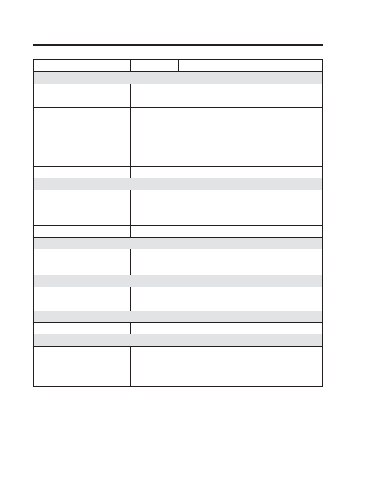
GENERAL PRINTER SPECIFICATIONS
SPECIFICATION CL408e CL412e CL608e CL612e
PRINT
Method Direct or Thermal Transfer
Speed (User Selectable) 2 to 6 ips
50 to 150 mm/s
Print Module (Dot Size) .0049 in.
.125 mm
Resolution 203 dpi
8 dpmm
Maximum Print Width 4.1 in.
104 mm
Maximum Print Length 49.2 in.
1249 mm
MEDIA
Minimum Width .87 in. (22 mm) 1.96 in. (50 mm)
Minimum Length .24 in. (6 mm) .78 in. (20 mm)
Maximum Width 5.1 in. (131 mm) 7 in. (178 mm)
Type Die Cut Labels, Fan-Fold, Tag Stock or Continuous
Caliper .010 in. (.25 mm)
Roll OD (max) 8.6 in. (218 mm), Face-In Wind
Core ID (min) 1.5 in. (38 mm)
.0033 in.
.083 mm
305 dpi
12 dpmm
32.8 in.
833 mm
.0049 in.
.125 mm
203 dpi
8 dpmm
6.0 in.
152 mm
49.2 in.
1249 mm
4to8ips
100 to 200 mm/s
.0033 in.
.083 mm
305 dpi
12 dpmm
6.5 in.
164mm
32.8 in.
833 mm
Core ID (Recommended) 3 in. (76 mm)
SENSING
Transmissive See-thru Movable
Reflective Eye-Mark Movable Fixed
Continuous Form Sensor not used
RIBBON
Maximum Width 4.4 in. (111 mm) 6.75 in. (172 mm)
Length 1475 ft. (450 m) 1345 ft (410 m)
Thickness 4.5 micron, Face-In Wind
All specifications subject to change without notice.
Page 1-2 PN 9001074 Rev. B SATO CL Series “e” Printers
Page 11

Section 1. Printer Overview
SPECIFICATION CL408e CL412e CL608e CL612e
CONTROLS AND SIGNALS
(1)
(1)
(1)
(1)
Green
Red
Red
Red
On-Line LED Status = Green
Power LED None Green
Media Out LED Status = Red
Ribbon Out LED Status = Red
Error LED Status = Red
LCD Panel 2 Line x 16 Character
On/Off-Line Switch Front Panel
Label Feed Switch Front Panel
Power On/Off Switch Rear Panel
POTENTIOMETER ADJUSTMENTS
Print Darkness Front Panel
Pitch Front Panel
Offset Front Panel
Display None Front Panel
INTERFACE MODULES
Parallel IEEE1284 Parallel
Serial RS232C (9600 to 57,600 bps)
RS422/485 (9600 to 57,600 bps)
Serial Protocol Hardware Flow Control (Ready/Busy)
Software Flow Control (X-On/X-Off)
Bi-directional Status
Universal Serial Bus USB Version 1.1
Ethernet 10/100BaseT
Data Transmission ASCII Format
PROCESSING
CPU 32 Bit RISC
Flash ROM 2 MB
SDRAM 16 MB
Receive Buffer 2.95 MB
Optional Flash ROM 4 MB
Optional PCMCIA Memory 16 MB Flash or 4 MB SRAM
(1) Single two color (Red, Green) LED.
All specifications subject to change without notice.
SATO CL Series “e” Printers PN 9001074 Rev. B Page 1-3
Page 12
Section 1. Printer Overview
CHARACTER FONTS
SPECIFICATION CL408e CL608e CL412e CL612e
MATRIX FONTS
U Font (5 dotsWx9dots H)
S Font (8 dotsWx15dots H)
M Font (13 dotsWx20dots H)
XU Font (5 dotsWx9dots H) Helvetica
XS Font (17 dots Wx 17 dots H) Univers Condensed Bold
XM Font (24 dots W x 24 dots H) Univers Condensed Bold
OA Font (15 dotsWx22dots H) OCR-A (22 dotsWx33dots H) OCR A
OB Font 20 dotsWx24dots H) OCR-B (30 dotsWx36dots H) OCR B
AUTO SMOOTHING FONTS
WB WB Font (18 dots W x 30 dots H)
WL WL Font (28 dotWx52dots H)
XB XB Font (48 dotsWx48dots H) Univers Condensed Bold
XL XL Font (48 dotWx48dots H) Sans Serif
VECTOR FONT
Proportional or Fixed Spacing
Font Size 50 x 50 dots to 999 x 999 dots
Helvetica, 10 Font Variations
AGFA®RASTER FONTS
A Font CG Times, 2 to 99 pt
B Font CG Triumvirate, 2 to 99 pt
DOWNLOADABLE FONTS
Bit Mapped TrueType Fonts with Utility Program
CHARACTER CONTROL
Expansion up to 12X in either the X or Y coordinates
Character Pitch control
Line Space control
Journal Print facility
0°, 90°, 180° and 270° Rotation
All specifications subject to change without notice.
Page 1-4 PN 9001074 Rev. B SATO CL Series “e” Printers
Page 13

Section 1. Printer Overview
BAR CODES
SPECIFICATION CL408e CL608e CL412e CL612e
SYMBOLOGIES
Bookland (UPC/EAN Supplemental)
EAN-8, EAN-13
CODABAR
Code 39
Code 93
Code 128
Interleaved 2 of 5
Industrial 2 of 5
Matrix 2 of 5
MSI
POSTNET
UCC/EAN-128
UPC-A and UPC-E
Data Matrix
Maxicode
PDF417
Micro PDF417
Truncated PDF417
QR Code
Ratios 1:2, 1:3, 2:5 User definable bar widths
Bar Height 4 to 600 dots, User programmable
Rotation 0°, 90°, 180° and 270°
OTHER FEATURES
Sequential Numbering Sequential numbering of both numerics and bar codes
Custom Characters RAM storage for special characters
Graphics Full dot addressable graphics, SATO Hex/Binary, .BMP or .PCX
formats
Form Overlay Form overlay for high-speed editing of complex formats.
All specifications subject to change without notice.
SATO CL Series “e” Printers PN 9001074 Rev. B Page 1-5
Page 14

Section 1. Printer Overview
PHYSICAL
SPECIFICATION CL408e CL412e CL608e CL612e
DIMENSIONS
Wide 10.7 in. (271 mm) 13.8 in. (352 mm)
Deep 16.9 in. (430 mm) 16.9 in. (429 mm)
High 12.6 in. (321 mm) 11.7 in. (298 mm)
WEIGHT 28.7 lbs (13 Kg) 41.9 lbs (19 Kg)
POWER REQUIREMENTS
Voltage
Power Consumption 50W Idle
130W Operating
ENVIRONMENTAL
Operating Temperature 41° to 104°F (5° to 40°C)
Storage Temperature -0° to 104°F (-20° to 40°C)
Operating Humidity 15-85 % RH, non-condensing
Storage Humidity Max 90% RH, non-condensing
Electrostatic Discharge 8KV
REGULATORY APPROVALS
Safety UL, CSA
RFI/EMI FCC Class A
All specifications subject to change without notice.
110V(±10 %)
220V (±10 %)
50/60 Hz (±1%)
50W Idle
210W Operating
Page 1-6 PN 9001074 Rev. B SATO CL Series “e” Printers
Page 15

Section 1. Printer Overview
OPTIONAL ACCESSORIES
ACCESSORY CL408 CL412 CL608 CL612
MEMORY EXPANSION One slot for PCMCIA Memory Cards (up to 16 MB Flash or 4 MB
SRAM) and/or 4MB internal Flash ROM. Can be used for Graphic File
storage, print buffer expansion, format storage and downloaded
TrueType fonts.
CALENDAR An internally mounted Date/Time clock that can be used to date/time
stamp labels at the time of printing.
LABEL CUTTER Internal attachment allowing labels to be cut at specified intervals.
Controlled through programming.
LABEL DISPENSER Internal attachment allowing
labels to be peeled from backing
for immediate (on demand)
application. Internal backing
take-up.
LABEL REWINDER External option rewinds labels onto a roll after they are printed.
PARALLEL INTERFACE IEEE1284 Parallel Interface Module
SERIAL INTERFACE High Speed Serial RS232 Interface Module
UNIVERSAL SERIAL I/F USB Interface Module
ETHERNET INTERFACE 10/100BaseT Interface Module
COAX/TWINAX INTERFACE Coax/Triax Interface Module. Coax I/F emulates an IBM 3287-2
printer with a standard Type A BNC connector. Twinax I/F emulates
IBM 5224, 5225, 5226 or 4214 printers with auto-terminate/cable-thru
capabilities.
All specifications subject to change without notice.
Internal attachment allowing
labels to be peeled from backing
for immediate (on demand)
application. Backing take-up
mounted externally to rear of
printer.
SATO CL Series “e” Printers PN 9001074 Rev. B Page 1-7
Page 16

Section 1. Printer Overview
This page left intentionally blank.
Page 1-8 PN 9001074 Rev. B SATO CL Series “e” Printers
Page 17

INTRODUCTION
This section is provided to assist you in taking the CL Series Printer from the shipping
container to the application environment. Where the physical differences between the
printer models are significant (such as loading paper and ribbons), separate sections
for each of the models are used for clarity.
The following information is provided in this section:
SECTION 2.
INSTALLATION
Unpacking and Parts Identification
•
Setting Up the Printer
•
Loading Labels or Tags
•
• Loading the Ribbon
• Operator Panel
SATO CL Series “e” Printers PN 9001074 Rev. B Page 2-1
Page 18
Section 2. Installation
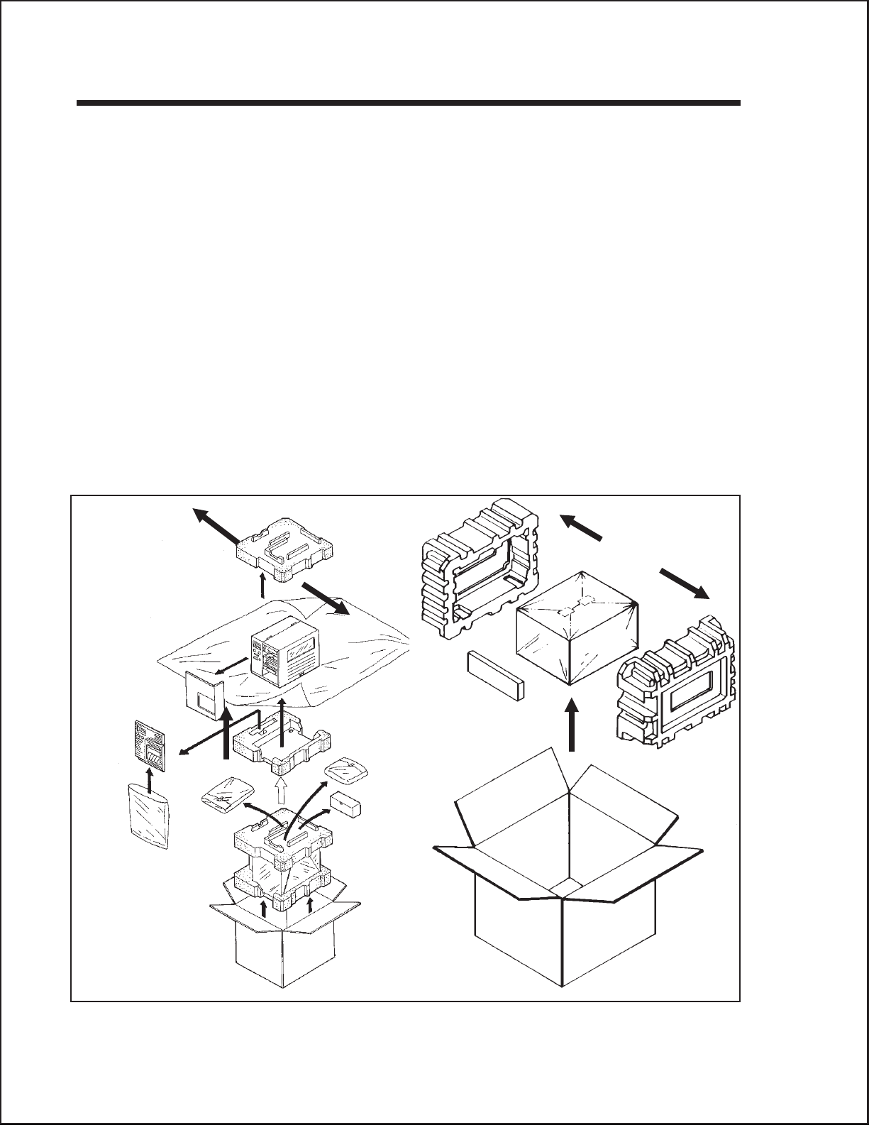
UNPACKING AND PARTS IDENTIFICATION
Consider the following when unpacking the printer:
The box should stay right-side up.
•
Lift the printer out of the box carefully.
•
Remove the plastic covering from the printer.
•
For the CL4XX printers, remove the Front Access Door from its protective
•
bag and attach it to the printer.
Remove the accessory items from their protective containers.
•
If the printer has been stored in a cold environment, allow it to reach room
•
temperature before powering it on.
Set the printer on a solid, flat surface. Inspect the shipping container and
•
printer for any signs of damage that may have occurred during shipping.
NOTE: The following illustrations are representative only. Your printer may not be
packed exactly as shown here, but the unpacking steps are similar.
CL4XX Packaging CL6XX Packaging
Page 2-2 PN 9001074 Rev. B SATO CL Series “e” Printers
Page 19

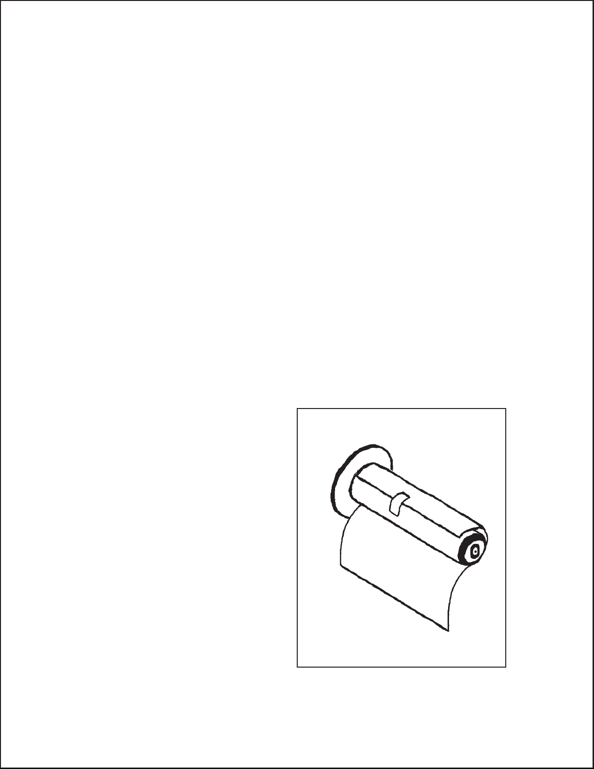
Verify that you have the following materials when unpacking:
Printer
•
Power Cord
•
Extra Ribbon Core
•
Section 2. Installation
CL Printer
Operator Manual
SETTING UP THE PRINTER
Consider the following when setting up the printer:
•
Locate a solid flat surface with adequate room to set the printer. Make sure
there is enough room at the top and right-hand (facing the printer) side to
provide clearance for the label access door to swing open.
•
The location should be near the host computer or terminal. The maximum
distance for RS232 cables is 35 feet and six feet for IEEE1284 Parallel
cables. Cables can be purchased locally, and their configuration will depend
upon the host system being used.
Power Cable
Extra Ribbon Core
•
For information on interfacing the printer to a host system, see
Section 6: Interface Specifications.
SATO CL Series “e” Printers PN 9001074 Rev. B Page 2-3
Page 20

Section 2. Installation
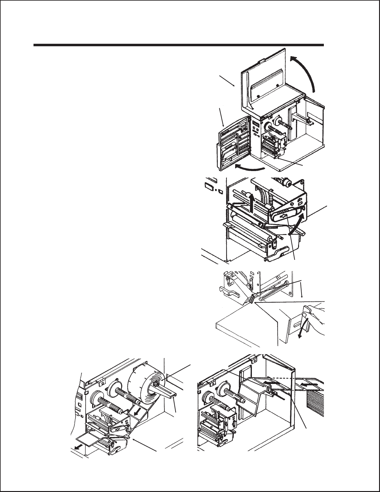
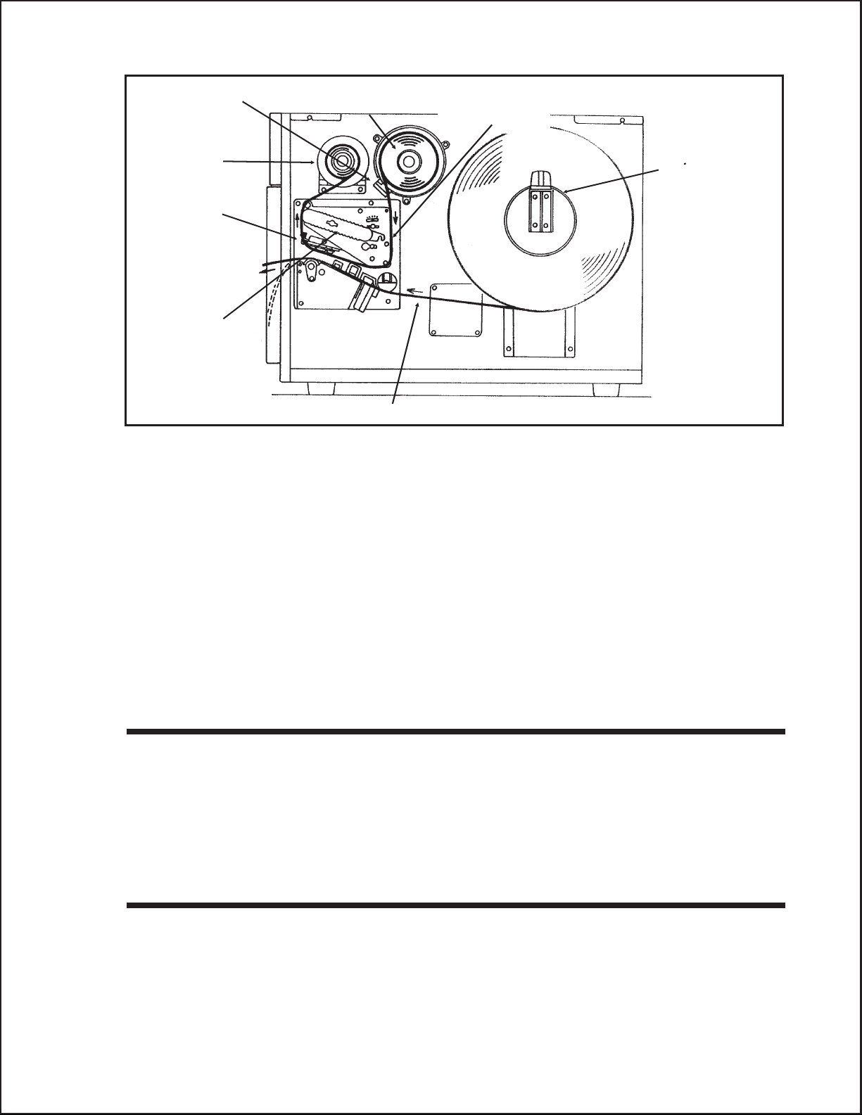
LOADING LABELS, TAGS AND RIBBON CL608e and CL612e
LOADING LABELS OR TAGS
1. Open the Side Access Door by
swinging it up and to the left. The
hinge system automatically
dampens the movement to prevent
the door from inadvertently falling
and possibly causing injury to the
operator.
2. Open the Print Head Assembly
by pushing the Head Latch
toward the rear of the printer. The
Print Head Assembly is
spring-loaded and will
automatically open as soon as the
Head Latch is disengaged.
Head Latch
3. Push the Label Supply Guide to the outside of the printer to give the maximum
label width.
4. Release the Label Roll Support by pulling outward at the top and swing it
down and out of the way.
5. If using roll labels (or tags), load the roll onto the Label Supply Spindle so
that the printing side of the labels faces upwards as it unwinds from the roll. The
labels should be wound face-in. Push the roll all the way to the inside of the
printer and push the Label Supply Guide snugly against the outside of the
label roll.
6. If using fanfold labels (or tags) set them on a flat surface behind the printer. Pass
the labels (printing side up) through the slot and under the Label Supply
Spindle.
7. Open the Label Hold-Down by
squeezing the green tab and the
release tab together. The Label
Hold-down is spring loaded and
will open automatically when the
latch is disengaged. Feed the
Sensor Adjust
Cap Screw
Sensor Adjust
Tab
labels under the Label Guide,
under the Label Hold-Down,
through the Print Head
Assembly and out the front of
the printer.
8. Inspect the label routing and verify
that the path matches that
illustrated in the Label Loading
Page 2-4 PN 9001074 Rev. B SATO CL Series “e” Printers
Label Hold-Down
Page 21

Section 2. Installation
diagram. Set the Adjustable
Label Guide to keep the labels
against the inside of the printer.
9. Close the Label Hold-Down by
pushing downward on the green
tab until it latches closed.
NOTE: If the Label Dispenser option
has been purchased, see Appendix A,
for proper label routing instructions.
10. Adjust the Label Sensor
Assembly to the correct position
by loosening the Sensor Adjust
Cap Screw located on the front side of the Label Hold-Down and moving the
Sensor Adjust Tab to the correct position. After it is correctly positioned,
retighten the Sensor Adjust Cap Screw.
11. If the ribbon is already loaded, close the Print Head Assembly by pushing
downward on the green tab until it latches closed.
12. If the ribbon is not loaded, see the following description for loading instructions.
Media Knob
Printed Labels
Dispenser Routing
Label Guide
Label Supply
Guide
Label Roll
Support
Label Roll
Label Backing
SATO CL Series “e” Printers PN 9001074 Rev. By Page 2-5
Page 22
Section 2. Installation
12. Adjust the Media Knob based on the media you have loaded. For media up to
2.3 inches wide, use the “1” position, for media between 2.3 and 4.6 inches wide,
use the “2” position. For media wider than 4.6 inches, use the “3” position. If you
use media narrower than 7 inches, using the wrong setting can void the print
head warranty due to the excessive pressure.
Caution: Using media narrower than the maximum print width may cause excess
head wear due to the label edge.
LOADING THE RIBBON
1. Open the Side Access Door by swinging it up and to the left. The hinge system
automatically dampens the movement to prevent the door from inadvertently
falling and possibly causing injury to the operator.
2. Open the Print Head Assembly by pushing the Head Latch toward the rear
of the printer. The Print Head Assembly is spring-loaded and will
automatically open as soon as the Head Latch is disengaged.
3. Locate the Extra Ribbon Core supplied with the printer. Place the core on the
Ribbon Rewind Spindle, pushing it all the way to the inside of the spindle.
Note that the new empty core of each subsequent roll becomes the next rewind core.
4. Load the ribbon onto the Ribbon Supply Spindle, also pushing it all the way
to the inside of the spindle. The dull side of the ribbon should be facing down as it
travels through the Print Head Assembly.
5. Feed the leader portion of the
ribbon through the Print Head
Assembly and up to the Ribbon
Rewind Spindle following the
routing shown in the diagram.
6. Load the ribbon behind and over
the top of the Ribbon Rewind
Spindle and tape it to the Extra
Ribbon Core. Make sure it
matches the ribbon path shown in
the diagram.
7. Manually turn the Rewind
Spindle to wrap the ribbon onto
the core one to two turns to secure
it.
8. If the labels or tags are already
loaded, close the Print Head
Assembly by pushing downward
on the green tab until it latches
closed.
NOTE: Run a test print to ensure that the labels and ribbons were loaded correctly.
See the “Test Print” section on page 3-22 for instructions on how to run test prints.
Page 2-6 PN 9001074 Rev. B SATO CL Series “e” Printers
Page 23

Ribbon Roll
Ribbon Rewind
Spindle
Print Head
Assembly
Ribbon Path
Head Latch
Section 2. Installation
Ribbon Supply
Spindle
CAUTION: If your labels are less than the full width of the print head, the outside
edge will eventually wear out a small portion of the print head, resulting in an area
that will not print. Special care must be taken if you plan to use multiple widths of
labels, since the damaged portion of the print head caused from edge wear on a
more narrow label may affect the printing on a wider label. We suggest you plan your
print formats carefully to avoid using the area of possible damage on the print head
when using a wider label. The small area of damage will have no effect on printing
with the undamaged part of the print head.
Damage from a label edge is physical damage and is unavoidable. It is not covered
by warranty. It is possible to delay such damage by always ensuring that the ribbon
used is wider than the label stock. This will help to protect the print head from label
edge damage.
SATO CL Series “e” Printers PN 9001074 Rev. B Page 2-7
Page 24
Section 2. Installation
LOADING LABELS, TAGS AND RIBBON CL408e and CL412e
LOADING LABELS AND TAGS
1. Open the Top Access Door by
swinging it up and to the left. Open
the Front Access Door by pushing
down on the green Front Cover Latch
and swinging the door forward and to
the left. This gives access to the print
mechanism on three sides
Note: The Top Access Door must be
open before the Front Access Door
can be opened.
2. Open the Print Head Assembly by
rotating the green Head Latch
counter clockwise. The head is spring
loaded and will automatically raise to
the opened position
3. Push the Label Supply Guide to the
outside of the printer to give the
maximum label width.
Top Access
Door
Front Access
Door
Front Access
Door Latch
4. Clear access is provided to the label
path by pulling the top of the Outside
Label Guide down.
5. If using roll labels (or tags), load the
roll onto the Label Supply Spindle
so that the printing side of the labels
faces upwards as it unwinds from the
roll. Push the roll all the way to the
inside of the printer, raise the Label
Supply Guide and adjust its position
until it fits snugly against the outside of
the label roll.
Label Supply
Spindle
Head Latch
Outside Label
Guide
Label
Feed Slot
Outside Label Guide
Page 2-8 PN 9001074 Rev. B SATO CL Series “e” Printers
Page 25

6. If using fanfold labels (or tags) set
them on a flat surface behind the
printer and remove the cover from
the Feed Slot on the rear panel.
Pass the labels (printing side up)
through the slot and over the
Label Supply Spindle.
7. Route the labels under the Label
Hold-Down, through the Label
Sensor Assembly, under the
Print Head and out the front of the
print mechanism. Push the labels all the way to
the inside of the printer until they touch the
Inside Label Guide.
Note: Make sure the labels are routed
through the Label Sensor Assembly. If they
are not, the printer will react as if there are
no labels loaded and will refuse to print.
Sensor
Assembly
Sensor
Adjust
Knob
Section 2. Installation
Inside Label
Label Hold
Down
8. Adjust the Label Sensor Assembly
loosening the green Sensor Adjust knob
located on the bottom side of the Label
Transport Assembly and moving the
assembly to the correct position. After it is
Sensor
Assembly
correctly positioned, retighten the green Sensor Adjust knob.
9. Raise the Outside Label Guide to the closed
position and push the guide inward until it
barely contacts the outside edge of the labels.
Head Latch
10. If Ribbon is already loaded in the printer,
close the Print Head and latch it in the
down position.
11. Inspect the label routing and verify that the
path matches that illustrated in the Label
Loading diagram on the inside of the Top
Access Door.
12. Carefully feed several labels through the opening in the Front Access Door and
close it. After the Front Access Door is closed, the Top Access Door may be
closed. These covers have interlock switches and the printer will not operate if
either is open.
NOTE: If the Label Dispense Option has been purchased, see Appendix A, Optional
Accessories for instructions on how to route the label backing. For information on
how to enable this option, see Section 3: Printer Configuration.
SATO CL Series “e” Printers PN 9001074 Rev. B Page 2-9
Page 26

Section 2. Installation
LOADING THE RIBBON
1. Open the Top and Front Access
Doors.
2. Open the Print Head Assembly by
rotating the green the Head Latch
counter clockwise. The print head is
spring loaded and will raise to the open
position as soon as the latch is released.
3. Locate the Extra Ribbon Core
supplied with the printer. Place the core
on the Ribbon Rewind Spindle,
pushing it all the way to the inside of
the spindle. Note that the new empty core
of each subsequent roll becomes the next
rewind core.
Ribbon Supply
Roll
Empty Core
Head Latch
4. Load the ribbon onto the Ribbon
Supply Spindle, pushing it all the
way to the inside of the spindle. The
dull side of the ribbon should be facing
down as it travels through the Print
Head Assembly.
5. Feed the leader portion of the ribbon
through the Print Head Assembly
and up to the Ribbon Rewind
Spindle following the routing shown
in the diagram.
6. Load the ribbon behind and over the
top of the Ribbon Rewind Spindle
and tape it to the Extra Ribbon
Core. Make sure it matches the ribbon
path shown in the diagram.
7. Manually turn the Ribbon Rewind
Spindle to wrap the ribbon onto the
core one to two turns to secure it.
Tape
8. If the labels or tags are already loaded,
close the Print Head Assembly by
rotating the green Head Latch
clockwise until it latches closed and
close the Front and Top Access
Doors.
NOTE: Run a test print to ensure that the
labels and ribbons were loaded correctly.
See the “Test Print” section on page 3-22 for instructions on how to run test prints.
Page 2-10 PN 9001074 Rev. B SATO CL Series “e” Printers
Page 27
Section 2. Installation
Ribbon Roll
Ribbon Rewind
Spindle
Print Head
Assembly
Head Latch
CAUTION: If your labels are less than the full width of the print head, the outside
edge will eventually wear out a small portion of the print head, resulting in an area
that will not print. Special care must be taken if you plan to use multiple widths of
labels, since the damaged portion of the print head caused from edge wear on a
more narrow label may affect the printing on a wider label. We suggest you plan your
print formats carefully to avoid using the area of possible damage on the print head
when using a wider label. The small area of damage will have no effect on printing
with the undamaged part of the print head.
Ribbon Supply
Spindle
Ribbon Path
Label Supply
Spindle
Label Path
Damage from a label edge is physical damage and is unavoidable. It is not covered
by warranty. It is possible to delay such damage by always ensuring that the ribbon
used is wider than the label stock. This will help to protect the print head from label
edge damage.
LABEL SENSOR ADJUSTMENTS CL608e and CL612e
The Gap (transmissive) sensor on the CL608e and CL612e can be adjusted over a
limited range. It is located in the Label Hold-Down Assembly and can be
adjusted by loosening the Sensor Adjust Cap Screw on the front of the Label
Hold-Down and sliding the Sensor Adjust Tab to the desired position. The Gap
sensor can be adjusted from a minimum of 1.0 in. (25mm) to a maximum of 3.5 in.
(90mm). The Eye Mark sensor is fixed at 0.33 in. (9mm).
LABEL SENSOR ADJUSTMENTS CL408e and CL412e
Both the Eye-Mark (refelective)and Gap (transmissive) sensors on the CL408e and
CL412e can be adjusted over a limited range. They are both located in the Label
Sensor Unit. The assembly can be adjusted by loosening the green Sensor Adjust
knob located underneath the Label Transport Assembly and sliding the Label
Sensor Unit to the desired position. The Gap sensor can be adjusted from a
SATO CL Series “e” Printers PN 9001074 Rev. B Page 2-11
Page 28
Section 2. Installation
minimum of 0.67 in. (17mm) to a maximum of 2.5 in. (64 mm), and the Eye-Mark
from a minimum of 0.25 in. (6mm) to a maximum of 2.1 in. (53mm).
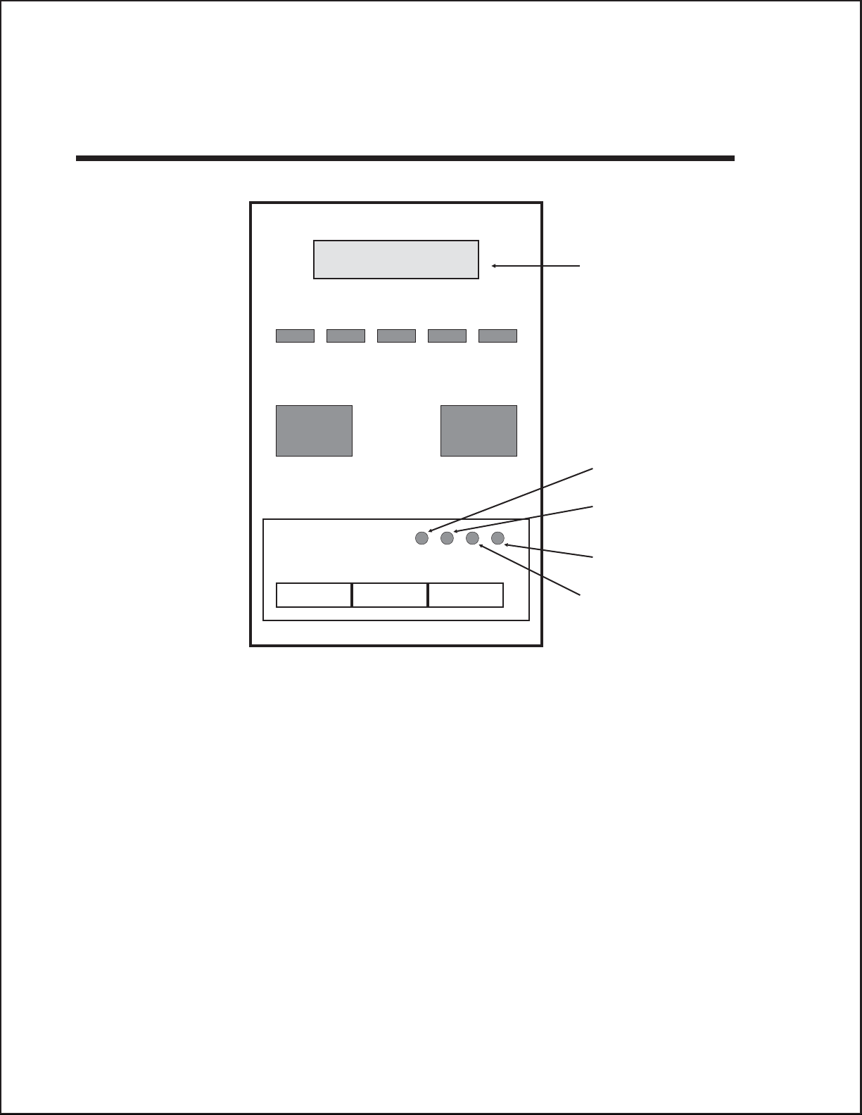
OPERATOR PANEL CL608e and CL612e
LCD
DISPLAY
PANEL
LINE LABEL RIBBON ERRORPOWER
LINE FEED
DISPLAY
PITCH
PRINT
Reserved
DSW2 DSW3
OFFSET
The CL608e/CL612e Operator Panel consists of five LED indicators, two
momentary contact switches, three DIP switches, four adjustment potentiometers and
one LCD Display. All of these are accessible from the front of the printer. They are
used to set the printer operating parameters and to indicate the status of the printer
to the operator. After you power on the printer, familiarize yourself with the keys and
indicators as it will help you understand the configuration process.
PRINT: Potentiometer to adjust print darkness (fine tuning).
OFFSET: Potentiometer to adjust amount of back/forward feed
for dispenser/cutter/tear-off bar position (+/-3.75 mm)
PITCH: Potentiometer to adjust home position of the label
(+/- 3.75 mm). Affects stop position of label feed, print
position and dispense position.
DISPLAY: Potentiometer to adjust the contrast of the LCD.
POWER: LED, illuminated when the power is on.
Page 2-12 PN 9001074 Rev. B SATO CL Series “e” Printers
Page 29

Section 2. Installation
LABEL: LED, illuminated when label supply is out.
RIBBON: LED, illuminated when ribbon motion sensor does not
detect any ribbon motion.
ERROR: LED, illuminated when there is a system fault such as
an open print head.
ONLINE: LED, illuminated when printer is ready to receive data.
It is turned on and off by toggling the LINE key. This
indicator will blink while the printer is receiving data.
LINE: Momentary switch. Pressing this key toggles the printer
between the on-line and off-line mode. When the
printer is on-line, it is ready to receive data from the
host. This key acts as a pause during a print job by
taking the printer off-line. It can also be used as a
Pause function key to stop label during the printing
process.
FEED: Momentary switch. Pressing this key feeds one blank
label through the printer when it is off-line. When the
printer is on-line, another copy of the last label will be
printed (can be disabled via the LCD panel).
DSW2-3: Located behind the Front Access Door. DIP switch
array to set operational parameters of the printer.
DSW1 is used to set the RS232 parameters and is
located on the RS232 interface board.
LCD: 2 Line x 16 Character LCD display. Used for setting
operational parameters of the printer.
SATO CL Series “e” Printers PN 9001074 Rev. B Page 2-13
Page 30
Section 2. Installation
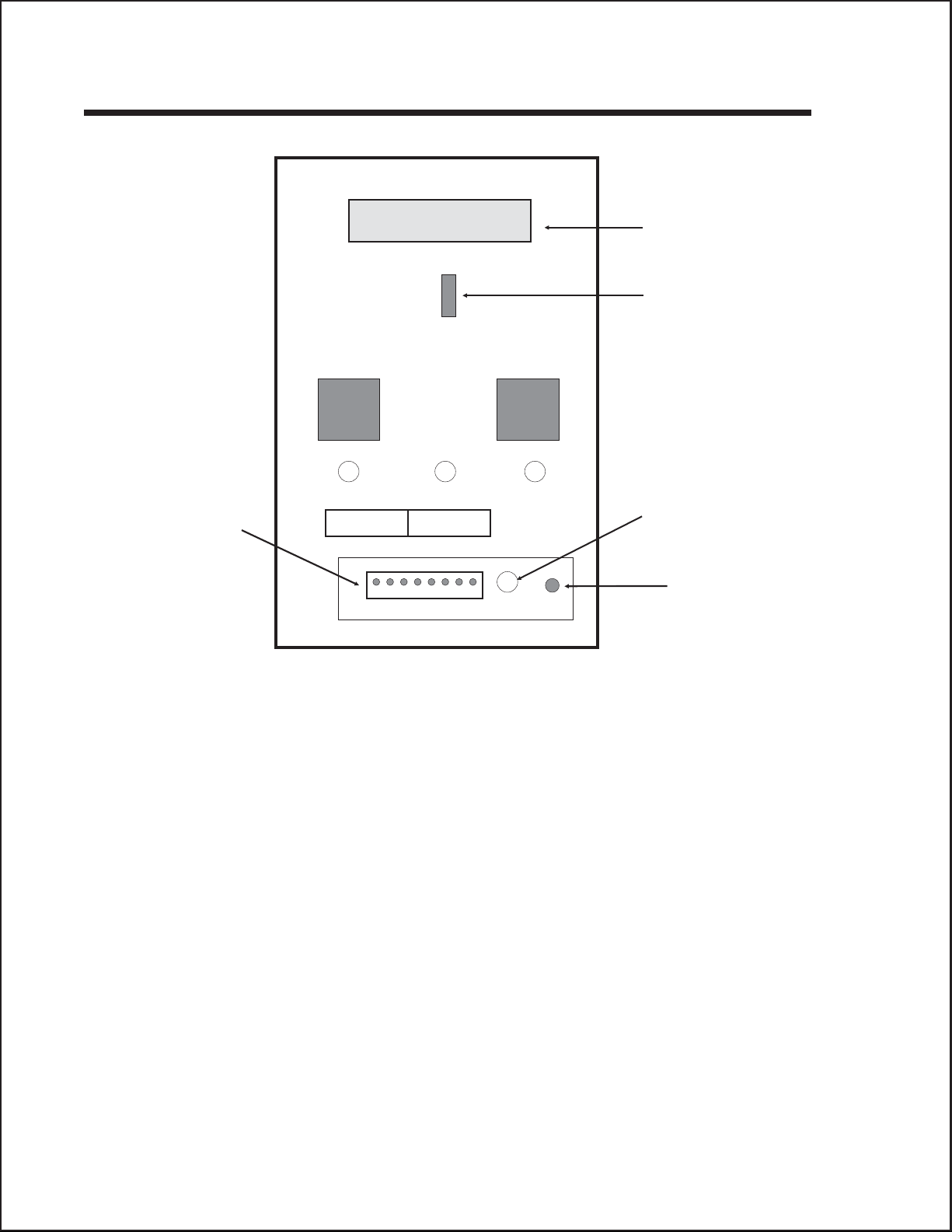
OPERATOR PANEL CL408e and CL412e
LCD
DISPLAY
PANEL
TWO-COLOR
STATUS LED
LINE FEED
OPTION
CONNECTOR
xxx
PITCHOFFSEPRINT
DSW2 DSW3
x
LABEL TAKEN
THRESHOLD
ADJUST
LABEL
TAKEN LED
Note: DSW1 (RS232 Parameter Select) is located on the RS232 Interface Board.
The CL408e/CL412e Operator Panel consists of one two-color (red and green)
LED indicator, two momentary contact switches, two DIP switches (a third is located
on the RS232 interface card), four adjustment potentiometers and one LCD Display.
All of these are accessible from the front of the printer, however some are not
accessible unless the front cover is open. They are used to set the printer operating
parameters and to indicate the status of the printer to the operator. After you power
on the printer, familiarize yourself with the keys and indicators as it will help you
understand the configuration process.
PRINT: Located behind the Front Access Door. Potentiometer
to adjust print darkness (fine tuning).
OFFSET: Located behind the Front Access Door. Potentiometer
to adjust amount of back/forward feed for
dispenser/cutter/tear-off bar position (+/- 3.75 mm)
PITCH: Located behind the Front Access Door. Potentiometer
to adjust home position of the label (+/- 3.75 mm).
Affects stop position of label feed, print position and
dispense position.
Page 2-14 PN 9001074 Rev. B SATO CL Series “e” Printers
Page 31

Section 2. Installation
STATUS: Two-color (Red, Green) LED that indicates the
following status conditions:
Green - Illuminated when printer is ready to receive
data. It is turned on and off by toggling the LINE
key.
Red -Illuminated when there is a system fault such
as an open print head.
LINE: Momentary switch. Pressing this key toggles the printer
between the on-line and off-line mode. When the
printer is on-line, it is ready to receive data from the
host. This key acts as a pause during a print job by
taking the printer off-line. It can also be used as a
Pause function key to stop label during the printing
process.
FEED: Momentary switch. Pressing this key feeds one blank
label through the printer when it is off-line. When the
printer is on-line, another copy of the last label will be
printed (can be disabled via the LCD panel).
DSW2-3: Located behind the Front Access Door. DIP switch
array to set operational parameters of the printer.
DSW1 is used to set the RS232 parameters and is
located on the RS232 interface board.
LCD: 2 Line x 16 Character LCD display. Used for setting
operational parameters of the printer.
LABEL TAKEN
THRESHOLD:
Located behind the Front Access Door. This
potentiometer is used to adjust the sensing level of the
Label Taken Sensor. Active only when the Label
Dispense option is installed.
OPTION CONNECTOR: Located behind the Front Access Door. This connector
is used for the cutter and dispenser optional
accessories.
LABEL TAKEN: Located behind the Front Access Door. This LED is
illuminated when a label is not present in the Label
Taken Sensor. If it is not illuminated, a label has been
detected in the sensor and printing will be inhibited until
it is removed. This LED is active only when the Label
Dispense option is installed. It is used to adjust the
Label Taken Sensor threshold.
SATO CL Series “e” Printers PN 9001074 Rev. B Page 2-15
Page 32

Section 2. Installation
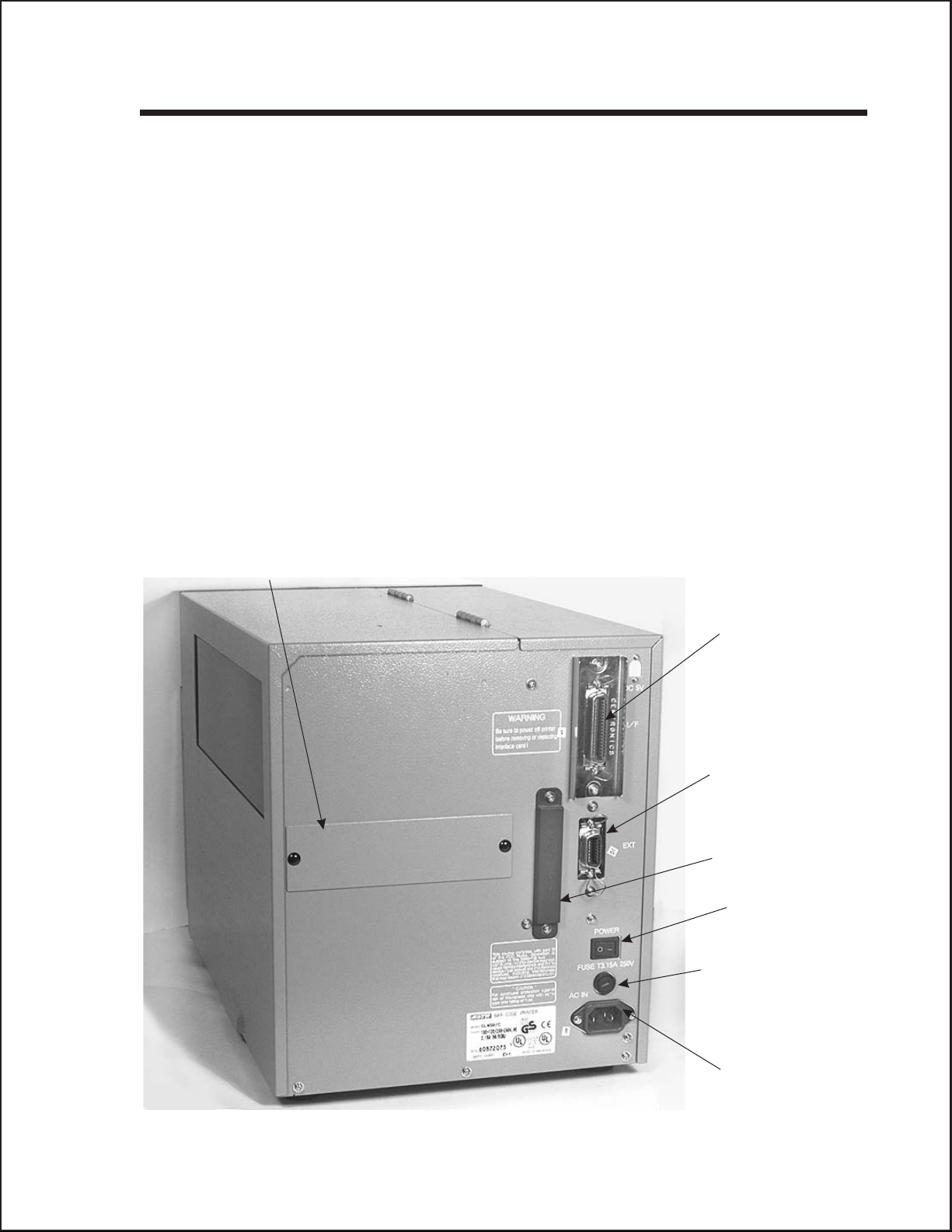
REAR PANEL CL608e and CL612e
Power On/Off Switch: Turns power On or Off.
AC Input: Input 115V 50/60 Hz connector. Use the cable
provided.
AC Fuse: Input power protection. Type 3A/250V.
Interface Slot: Slot to plug in an interface adapter. An adapter must be
connected before the printer is operational.The adapter
types available are:
RS232C Serial I/F Module, DB-25P.
IEEE1284 Parallel I/F Module, AMP 57-40360
Universal Serial Bus I/F Module
Ethernet 10/100BaseT I/F Module
Memory Card Slot: Two connectors for optional PCMCIA Memory Cards.
EXT: External signal connector, AMP 57-60140.
Cover Plate
Remove for access to Dispenser
and Fan-Fold Slots
PCMCIA Memory
Expansion slot
I/F Module
Parallel Shown
Power Switch
AC Fuse
External Accesory
Connector
AC Power Input
Connector
Page 2-16 PN 9001074 Rev. B SATO CL Series “e” Printers
Page 33
Section 2. Installation
REAR PANEL CL408e and CL412e
Power: Switch to turn power On or Off.
AC Input: Input 115V 50/60 Hz connector. Use the cable
provided.
AC Fuse: Input power protection. Type 3A/250V.
Interface Slot: Slot to plug in an interface adapter. An adapter must be
connected before the printer is operational.The adapter
types available are:
RS232C Serial I/F Module, DB-25P.
IEEE1284 Parallel I/F Module, AMP 57-40360
Universal Serial Bus I/F Module
Ethernet 10/100BaseT I/F Module
Memory Card Slot: Two slots for optional PCMCIA Memory Cards.
EXT: External signal connector for Accessories, AMP
57-60140.
Cover Plate
Remove for access to
Fan-Fold Slots
I/F Module
Parallel Shown
External Accesory
Connector
PCMCIA Memory
Expansion slot
Power Switch
AC Fuse
AC Power Input
Connector
SATO CL Series “e” Printers PN 9001074 Rev. B Page 2-17
Page 34

Section 2. Installation
SWITCHES AND SENSORS CL608e and CL612e
Ribbon End Sensor: This sensor is a motion detector that signals the printer
when the ribbon supply is turning.
Head Open Switch: When the print head is opened, this switch is activated
and the printer will stop printing.
Label Sensor Unit: This sensor unit contains two types of sensors, one for
label gap and one for Eye-Mark sensing.
Ribbon
Motion
Sensor
Label Sensor
Unit
Backing
Paper Inside
Edge
Miminum Eye-Mark Size
.12 in (3 mm) W x .24 in. (6 mm) L
0.33" (9 mm) Eye-Mark Sensor
1.0" (25 mm) to 3.5" (90 mm)
Label Gap Sensor
Label Inside Edge
Label
Feed
Direction
Min. Inter-Label Gap
0.12" (3 mm)
CL608 and CL612 Label Sensor Positioning
Page 2-18 PN 9001074 Rev. B SATO CL Series “e” Printers
Page 35

Section 2. Installation
SWITCHES AND SENSORS CL408e and CL412e
Ribbon End Sensor: This sensor is a motion detector that signals the printer
when the ribbon supply is turning.
Head Open Switch: When the print head is opened, this switch is activated
and the printer will stop printing.
Label Sensor Unit: This sensor unit contains two types of sensors, one for
label gap and one for Eye-Mark sensing. The sensors
are adjustable over a limited range.
Front Access Door
Interlock:
Front Access
Door Interlock
Switch
This switch prevents printer operation when the Front
Access Door is open. The Top Access Door must be
open before the Front Access Door can be opened or
closed.
Ribbon
Motion
Sensor
Miminum Eye-Mark Size
.12 in (3 mm) W x .24 in. (6 mm) L
Label
Inside Label Guide
Backing
Paper Inside
Edge
0.25" to 2.1" (6 mm to 53mm)
Eye-Mark Sensor
Minimum
Inter-Label Gap
0.12" (3 mm)
0.67" to 2.5" (17mm to 64mm)
Label Gap Sensor
Note: These positions are different
from the M84XX printers.
Label Inside Edge
Feed
Direction
CL408 and CL412 Label Sensor Positioning
SATO CL Series “e” Printers PN 9001074 Rev. B Page 2-19
Page 36

Section 2. Installation
This page left intentionally blank.
Page 2-20 PN 9001074 Rev. B SATO CL Series “e” Printers
Page 37

SECTION 3.
CONFIGURATION
PRINTER DIP SWITCH CONFIGURATION
DIP Switch Panels
There are two DIP switches (DSW2 and DSW3) located inside the cover. These
switches can be used to set:
Thermal transfer or direct thermal mode
•
Label sensor enable/disable
•
Head check mode
•
Hex dump mode
•
• Single Job or Multi-Job Receive buffer
• Operation mode
In addition, a third DIP switch is located on the RS232 Serial Adapter module and is
used to set the RS232C transmit/receive parameters
Each switch is an eight section toggle switch. The ON position is always to the top. To
set the switches, first power the unit Off, then position the DIP switches. Finally, after
placing the switches in the desired positions, power the printer back on. The switch
settings are read by the printer electronics during the power up sequence. They will
not become effective until the power is cycled.
RS232 Transmit/Receive Setting (located on RS232 I/F Module)
Data Bit Selection (DSW1-1). This switch sets the printer to receive either 7 or 8
bit data bits for each byte transmitted.
DSW1
DSW1-1 SETTING
Off 8 data bits
On 7 data bits
ON
OFF
12345678
Parity Selection (DSW1-2, DSW1-3). These switches select the type of parity
used for error detection.
DSW1-2 DSW1-3 SETTING
Off Off No Parity
Off On Even
On Off Odd
On On Not Used
ON
OFF
12345678
DSW1
SATO CL Series “e” Printers PN 9001074 Rev. B Page 3-1
Page 38

Section 3. Configuration
Stop Bit Selection (DSW1-4). Selects the number of stop bits to end each byte
transmission.
DSW1-4 SETTING
Off 1 Stop Bit
On 2 Stop Bits
Baud Rate Selection (DSW1-5, DSW1-6). Selects the data rate (bps) for the
RS232 port.
DSW1-5 DSW1-6 SETTING
Off Off 9600
Off On 19200
On Off 38400
On On 57600
Protocol Selection (DSW1-7, DSW1-8). Selects the flow control and status
reporting protocols. See Section 6: Interface Specifications for more information.
(* Will select protocol for M-8400 if DSW2-8 is ON)
DSW1
ON
OFF
12345678
DSW1
ON
OFF
12345678
DSW1-7 DSW1-8 SETTING
Off Off Rdy/Bsy
Off On Xon/Xoff
On Off Bi-Com 3
On On Bi-Com 4*
ON
OFF
12345678
DSW1
Printer Set Up
Print Mode Selection (DSW2-1). Selects between direct thermal printing on
thermally sensitive paper and thermal transfer printing using a ribbon.
DSW2-1 SETTING
Off Therm Xfr
On Direct Therm
ON
OFF
12345678
DSW2
Sensor Type Selection (DSW2-2). Selects between the use of a label gap or a
reflective Eye-Mark detector.
DSW2-2 SETTING
Off Gap
On Eye-Mark
ON
OFF
12345678
DSW2
Page 3-2 PN 9001074 Rev. B SATO CL Series “e” Printers
Page 39

Section 3. Configuration
Head Check Selection (DSW2-3). When selected, the printer will check for head
elements that are electrically malfunctioning.
DSW2
DSW2-3 SETTING
Off Disabled
On Enabled
ON
OFF
12345678
Hex Dump Selection (DSW2-4). Selects Hex Dump mode.
DSW2-4 SETTING
Off Disabled
On Enabled
ON
OFF
12345678
DSW2
Receive Buffer Selection(DSW2-5). Selects the operating mode of the receive
buffer. See Section 6: Interface Specifications for more information.
DSW2-5 SETTING
Off Single Job
On Multi Job
ON
OFF
12345678
DSW2
Firmware Download (DSW2-6). Places the printer in the Firmware Download
mode for downloading new firmware into flash ROM.
DSW2-6 SETTING
Off Disabled
On Enabled
ON
OFF
12345678
DSW2
Protocol Code Selection (DSW2-7). Selects the command codes used for
protocol control. Refer to Appendix E for more information.
DSW2-7 SETTING
Off Standard
On Non-Std
ON
OFF
12345678
DSW2
M8400 Emulation Mode (DSW2-8). For emulating earlier series software
commands. Should be used only if problems are encountered when using existing
software. This switch will also affect the settings selected by DSW1-7 and DSW1-8.
DSW2-8 SETTING
Off Disabled
On Enabled
SATO CL Series “e” Printers PN 9001074 Rev. B Page 3-3
ON
OFF
12345678
DSW2
Page 40

Section 3. Configuration
Backfeed Sequence (DSW3-1). Backfeed is used to correctly position the label for
application and then retract the next label to the proper print position. This operation
can be performed immediately after a label is printed and used, or immediately prior
to the printing of the next label.
DSW3-1 DSW3-2 SETTING
Off Off Continuous
Off On Tear-Off
On Off Cutter
On On Dispenser
ON
OFF
12345678
DSW3
Label Sensor Selection (DSW3-3). Enables or disables the Label Sensor. If the
Sensor is enabled, it will detect the edge of the label and position it automatically. If
it is disabled, the positioning must be under software control using Line Feed
commands.
DSW3-3 SETTING
Off Sensor Used
On Not Used
ON
OFF
12345678
DSW3
Back-Feed Selection (DSW3-4). When Back-Feed is enabled, the printer will
position the last printed label for dispensing and retract it before printing the next
label. The amount of backfeed offset is adjustable .
DSW3
DSW3-4 SETTING
Off Enabled
On Disabled
ON
OFF
12345678
External Signal Interface. See Section 6: Interface Specifications for information
on the External Signals.
EXT Print Start Signal Selection (DSW3-5). Allows an external device to
initiate a label print for synchronization with the applicator. See Section 6: Interface
Specifications for a description of the signal level and requirements When DSW3-5 is
On, the unit is in the Continuous print mode, Backfeed is disabled and External
Signals are ignored.
DSW3-5 SETTING
Off Enabled
On Disabled
ON
OFF
12345678
DSW3
Page 3-4 PN 9001074 Rev. B SATO CL Series “e” Printers
Page 41

Section 3. Configuration
External Signal Type Selection (DSW3-6, DSW3-7). Both the polarity and
signal type (level or pulse) of the external print synchronizing signal can be selected.
See Section 6: Interface Specifications for a definition of signal types.
DSW3-6 DSW3-7 SETTING
Off Off Type 4
Off On Type 3
On Off Type 2
On On Type 1
ON
OFF
12345678
DSW3
Repeat Print via External Signal (DSW3-8). Allows the applicator to reprint
the last label of the print job. See Section 6: Interface Specifications for a description of
the signal requirements.
DSW3-8 SETTING
Off Disabled
On Enabled
ON
OFF
12345678
DSW3
Reserved for Future Use (DSW3-2)
SATO CL Series “e” Printers PN 9001074 Rev. B Page 3-5
Page 42

Section 3. Configuration
DEFAULT SETTINGS
SWITCH SELECTIONS
All switches are placed in the Off default position for shipping. This will result in the
following operating configuration:
Communications:
Protocol:
Sensor:
Receive Buffer:
Mode:
Label Sensor:
Backfeed:
External Signals:
8 data bits, no parity, 1 Stop bit, 9600 Baud
Ready/Busy
Gap Sensor
Multi Job
Batch/continuous
Sensor Used
Enabled
Enabled
(1)
(1) Only if RS232 I/F Module is installed.
SOFTWARE DEFAULT SETTINGS
The printer stores the software settings upon receipt and uses them until they are
again changed by receipt of a command containing a new setting. These settings are
stored in non-volatile memory and are not affected by powering the printer off. The
printer may be reset to use the default software settings by depressing the LINE and
FEED keys simultaneously while powering the printer on. You will be asked to
confirm that you want the printer default settings by selecting either YES or NO by
using the LINE key to step the cursor to the desired setting. If you select YES and
press the FEED key, the following default configuration will be stored:
CL408e CL412e CL608e CL612e
Print Darkness 3 2
Print Speed 4 in. per sec. 6 in. per sec.
Print Reference Vertical = 0000, Horizontal = 0000
Zero Slash
Auto On Line Enabled
Once the default operation is completed, a DEFAULT COMPLETED message will be
displayed on the LCD panel or a single beep will be heard if the printer does not have
an LCD panel. The printer should be powered off while this message is being
displayed (or after the beep is heard. This saves the default settings in the
non-volatile memory where they will be automatically loaded the next time the
printer is powered on.
Page 3-6 PN 9001074 Rev. B SATO CL Series “e” Printers
Page 43

POTENTIOMETER ADJUSTMENTS
PITCH
After the pitch has been set with the LCD Control Panel, it is sometimes desirable to
make minor adjustments. This can be done using the PITCH potentiometer on the
front panel. This potentiometer is set at the factory so that it has a range of +/- 3.75
mm. The midpoint setting should have no effect on the pitch. Turning the
potentiometer all the way clockwise should move the print position 3.75 mm up
towards the top edge of the label. Turning it all the way counterclockwise should
move the print position down 3.75 mm.
1. While depressing the FEED key on the front panel, power the printer on.
2. When you hear one beep from the printer, release the FEED key and the printer
will display on the LCD panel a message asking what type of Test Label you want
to print.
3. Use the LINE key to step to the Configuration selection and press the FEED key
to accept the selection.
Section 3. Configuration
4. Use the LINE key to select the Test Label Size. After the size is selected, press the
FEED key to accept the selection and the printer will begin to print test labels
continuously.
4. Adjust the PITCH potentiometer on the front panel until the first print position is
at the desired location on the label. If the potentiometer does not have enough
range, then you will have to change the pitch setting using the front panel display.
5. Press the FEED key to stop the printer.
6. To exit the Test Label mode, power the printer off andthen back on.
Adjusting the PITCH potentiometer will affect the stop position of the label.
BACKFEED OFFSET
When a label is printed it must be correctly positioned for dispensing and application.
The Backfeed adjustment is used to position the label so that it is fully dispensed and
ready for application. It may then be necessary to reposition the next label before
printing. The Backfeed (repositioning of the label)operation is enabled if DSW3-4 is
in the Off position. If Backfeed is enabled, placing DSW3-1 is in the Off position will
cause the backfeed operation to be performed immediately before each label is
printed. If DSW3-1 is in the On position, the backfeed operation is performed as soon
as the dispensed label has been printed and taken from the printer.
The amount of backfeed is controlled by the OFFSET potentiometer on the DIP
Switch Panel inside the cover. When turned all the way counterclockwise, the amount
of backfeed is +3.75 mm, and -3.75 mm when turned all the way counterclockwise.
1. Turn the printer on.
2. Press the LINE key to place the printer in the Off Line status.
SATO CL Series “e” Printers PN 9001074 Rev. B Page 3-7
Page 44

Section 3. Configuration
3. Press the FEED key to feed out a blank label.
4. Adjust the position using the OFFSET potentiometer on the front control panel
and feed another label by depressing the FEED key. Repeat this procedure until
the label is fully released from the liner.
DISPLAY
This potentiometer is used to adjust the contrast of the LCD display for optimum
viewing under various lighting conditions.
PRINT
The PRINT potentiometer is used to adjust the amount of heat (i.e., power) applied to
the head for printing. It provides a continuous range of adjustment. Maximum print
darkness is obtained by turning the potentiometer all the way clockwise and a
maximum counterclockwise setting will give the lightest print.
NOTE: The PRINT potentiometer adjustment will affect the darkness in all of the
command code speed and darkness ranges.
Page 3-8 PN 9001074 Rev. B SATO CL Series “e” Printers
Page 45

LCD PANEL PRINTER CONFIGURATION
The LCD Panel is used by the operator in conjunction with the LINE and FEED
switches to manually enter printer configuration settings. Many of these settings can
also be controlled via software commands and in the case of conflict between
software and control panel settings, the printer will always use the last valid setting.
If you load a label job that includes software settings and then enter a new setting via
the LCD panel, the manually set values will be used by the printer. If you set the
values manually and then download a job with software settings, the software
settings will be used.
There are nine modes of operation. To enter the desired mode, the KEY SEQUENCE
combination listed in the table below must be performed. The initial LCD display
message is shown for each mode.
MODE KEY SEQUENCE INITIAL DISPLAY PAGE
Section 3. Configuration
Normal POWER ONLINE
QTY:000000
Advanced LINE + POWER ADVANCED MODE 3-12
Test Print FEED + POWER TEST PRINT MODE
CONFIGURATION
Default Setting LINE + FEED + POWER DEFAULT SETTING
YES NO
Clear Non-Standard Protocol DSW2-7 ON + LINE + FEED
+ POWER
Protocol Code Download DSW2-7 ON + POWER USER DOWNLOAD 3-24
Hex Dump DSW2-4 ON + POWER ONLINE
ALT. PROTOCOL 3-24
QTY:000000
3-10
3-22
3-23
3-25
SATO CL Series “e” Printers PN 9001074 Rev. B Page 3-9
Page 46

Section 3. Configuration
NORMAL MODE
The printer initially powers on in the ONLINE mode. The user can access the User
Settings using the following procedures.
ONLINE
QTY:000000
OFFLINE
000000
PRINT DARKNESS
12345
PRINT SPEED
468
The LCD will display the ONLINE status on the top line and
the bottom line will contain the label quantity (QTY) status.
The messsge will be changed to OFFLINE whenever the
printer is switched offline by pressing the LINE key. As soon a
print job is received, the quantily line will indicate the number
of labels to be printed. As soon as the label job begins to print,
the display will indicate the number of labels in the print job
that remains to be printed.
Press the LINE key once. When the display changes to
OFFLINE, press the FEED and LINE keys simultaneously for
more than one second.
The LCD now displays the Print Darkness selections. The
current setting is indicated by a cursor over one of the range
settings.
1. Press the LINE key to step the cursor to the desired
setting.
2. Once the correct setting is highlighted, press the FEED
key to accept the selection and step the display to the
next adjustment.
The print speed selections are dependent upon the printer
model. The current setting is indicated by the underline cursor.
1. Use the LINE key to step the cursor to the desired
setting.
2. Once the correct setting is highlighted, press the FEED
key to accept the selection and step the display to the
next adjustment.
CL408e/CL412e CL608e/CL612e
2 ips 4 ips
3 ips 6 ips
4 ips 8 ips
5 ips
6 ips
Page 3-10 PN 9001074 Rev. B SATO CL Series “e” Printers
Page 47

Section 3. Configuration
PITCH OFFSET
+
00mm
The label Pitch is the distance from the leading edge (the
edge that comes out of the printer first) of a label and the
leading edge of the next label. The leading edge position of
the label can be adjusted relative to the print head +/- 49mm
in increments of 1mm. Once the position is set, it can be fine
adjusted +/- 3.75mm using the PITCH potentometer on the
Adjustment Panel.
1. The cursor will initially be positioned over the Pitch
Direction setting. Pressing the LINE key will step the
setting to the positive (+) or negative (-) selection. A
positive selection moves the leading edge of the label
forward (away from the print head) while a negative
selection moves the leading edge of the label back into
the mechanism.
2. Once the correct direction is selected, pressing the FEED
key will accept the setting and advance the cursor to the
Offset selection.
3. Use the LINE key to step the first digit of the counter to
the desired setting. The display will increment one step
each time the LINE key is pressed. The reading will
advance to a setting of 4 after which it will automatically
wrap and start at 0 again.
4. Press the FEED key to accept the setting and advance
the cursor to the second digit. Again use the LINE key to
step to the desired setting. Once it is correct, pressing the
FEED key will step to the next adjustment.
You may wish to print a test label after completing the
adjustments to ensure they are correct.
ABCDEFG
ABCDEFG
ABCDEFG
Moved with negative
(-) offset to print on
leading edge of the
label
Leading edge of the
label as detected by
Original (0 offset) first
line print position
Moved with positive
(+) offset to print on
trailing edge of label
Sensor Position
SATO CL Series “e” Printers PN 9001074 Rev. B Page 3-11
Page 48

Section 3. Configuration
CANCEL PRINT JOB
YES NO
CANCEL PRINT JOB
COMPLETED
If the printer has a print job(s) in memory, selecting YES will
cause the job(s) to be cleared. The default selection is NO. Be
sure you want to cancel the print job(s) before selecting yes as
the job(s) cannot be recovered and will have to be
retransmitted tyo the printer.
1. Use the LINE key to step the cursor to either the YES or
NO selection.
2. Once the correct setting is highlighted, pressing the FEED
key will accept the setting.
3. After the print job(s) have been cleared from memory, the
printer will display a COMPLETED message for 3 seconds
and then return to the initial ONLINE Normal Mode.
4. If you wish to change any of the settings, you must enter
the User Settings mode again by taking the printer
OFFLINE and pressing the LINE and FEED keys.
ADVANCED MODE
An Advanced Mode is provided to make adjustments that require only occasional
changes. Since they affect the basic operation of the printer, the procedure for
entering this mode is designed to prevent someone from accidently changing the
settings.
ADVANCED MODE
ZERO SLASH
YES NO
AUTO ONLINE
YES NO
The Advance Mode is entered by pressing the LINE key while
simultaneously turning power on. The printer will emit one long
beep after which the LINE key is released. Pressing the FEED
key will step the display to the first selection.
This setting determines if a zero is printed with a slash or
without a slash. This setting can also be controlled via
software commands. When YES is selected, the printer
internal fonts will have a slash through the center of the zero
character.
1. Use the LINE key to step the cusor to either the YES or
NO selection.
2. Once the correct setting is highlighted, pressing the FEED
key will accept the setting and advance the display to the
Auto Online display.
This setting determines the mode in which the printer powers
up. If the YES selection is made, the printer powers up in the
ONLINE mode and is ready to print. If NO is selected, the
printer powers up in the OFF LINE mode and must be
manually placed in the ON LINE mode by pressing the LINE
key before it is ready to print.
1. Use the LINE key to step the cursor to either the YES or
NO selection.
2. Once the correct setting is highlighted, pressing the FEED
key will accept the setting and advance the display to the
Print Offset display.
Page 3-12 PN 9001074 Rev. B SATO CL Series “e” Printers
Page 49

Section 3. Configuration
PRINT OFFSET
V:+000 H:+000
Vertical Offset is the distance down from the leading edge (the
edge of the label that comes out of the printer first) to the first
vertical print position. A positive setting moves the first print
position down the length of the label while making it negative
moves it up the length of the label. Horizontal Offset is
distance that the label image is shifted either to the right or left
on the label. The image is shifted to the left (towards the
inside edge of the label for a right-hand printer) for a positive
setting and it is shifted to the right (towards the outside edge
of the label) for a negative setting. This setting changes the
base reference point for all subsequent label jobs. It’s effect is
identical to the <ESC>A3 Base Reference point command.
Since the printer moves the label in discrete steps equal to the
size of the print dot, the units of measure for Vertical and
Horizontal Offset distance is dots. The maximum values that
can be set for each is +/-800.
1. Use the LINE key to step the first digit of the counter to
the desired setting. The display will increment one step
each timethe LINE key is pressed.
2. Press the FEED key to accept the setting and advance
the cursor to the second digit. Again use the LINE key to
step to the desired setting. Once it is correct, pressing the
FEED key will step to the next adjustment.
3. Once the setting is correct, pressing the FEED key will
accept the setting and advance to the next display.
You may wish to print a test label after completing the
adjustments to ensure they are correct.
Note: This setting can be overriden by the Base Reference
Point Command.
SET CALENDAR
YES NO
The Calendar Option is ia standard feature in all Se printers
allowing the date and time to be set manually using the LCD
Display or via the <ESC>WT Calendar Set command. The last
setting, set either manually via software command, received
by the printer will be the value used. The format of the display
is YY/MM/DD hh:mm (Year/Month/Day/hours:minutes).The
date format is fixed and cannot be changed.
To enable the Calendar feature (if installed), press the LINE
key until the cursor is over the the YES. If the Calendar
feature is to be disabled, press the LINE key until the cursor is
over the NO. When the desired setting is selected, press the
FEED key.
SATO CL Series “e” Printers PN 9001074 Rev. B Page 3-13
Page 50

Section 3. Configuration
CALENDAR
00/00/00 00:00
1. Year - The first display shown will have the two digit year
selection underlined. You can scroll through the dates by
pressing the LINE key. The year number will increase by
one each time the LINE key is pressed until it reaches its
maximum legal value (i.e., “99” for the year digits) at
which point it will wrap around to the “00” setting.
2. Month - After you have set the correct year, pressing the
FEED key will advance the cursor to the two digit Month
position. You can scroll through the numbers
corresponding to the month by pressing the LINE key. The
month number will increase by one each time the LINE
key is pressed until it reaches a value of “12” at which
point it will wrap around to the “01” setting.
3. Day - After you have set the correct month, pressing the
FEED key will advance the cursor to the two digit Day
position. You can scroll through the numbers
corresponding to the month date by pressing the LINE
key. The date number will increase by one each time the
LINE key is pressed until it reaches a value of “31” at
which point it will wrap around to the “01” setting.
4. Hour - After you have set the correct date, pressing the
FEED key will advance the cursor to the two digit Hour
position. You can scroll through the numbers
corresponding to the hour (using a 24 hour clock) by
pressing the LINE key. The hour number will increase by
one each time the LINE key is pressed until it reaches a
value of “24” at which point it will wrap around to the “01”
setting.
5. Minute- After you have set the correct hour, pressing the
FEED key will advance the cursor to the two digit Minute
position. You can scroll through the numbers
corresponding to the hour by pressing the LINE key. The
minute number will increase by one each time the line key
is pressed until it reaches a value of “60” at which point it
will wrap around to the “01” setting.
6. After you have set the minutes, pressing the FEED key
will accept the setting and advance to the Ignore CR/LF
selection.
IGNORE CR/LF
YES NO
Page 3-14 PN 9001074 Rev. B SATO CL Series “e” Printers
This selection tells the printer to strip out all carriage
return/line feed pairs (CRLF ) from the data stream, including
graphics and 2D bar codes. It is used primrily to maintain
compatibility with earlier models of SATO printers.
1. Use the LINE key to step the cusor to either the YES or
NO selection.
2. Once the correct setting is highlighted, pressing the FEED
key will accept the setting and advance the display to the
Character Pitch display.
Page 51

Section 3. Configuration
CHARACTER PITCH
FIXED PROP
ADVANCED MODE
This selection allows you to set the default character pitch to
either fixed character spacing or proportional character
spacing.
1. Use the LINE key to step the cursor to the desired setting.
2. Once the correct setting is highlighted, pressing the FEED
key will accept the setting and the display will return to the
Advanced Mode display.
Note: This command can be overriden by the <ESC>PR or
<ESC>PS Character Pitch Commands.
To exit the Advanced mode, power the printer off and then
back on.
CARD MODE
The Card Mode allows the operator to manage the Expanded Memory (PCMCIA Card
or Internal Expanded Flash ROM).
ADVANCED MODE
CARD MODE
The Card Mode is entered from the Advanced Mode display
by pressing the LINE key once.
The Card Mode display indicates that the printer is in the Card
Mode. To advance to the first selection, press the FEED key.
MEM SELECT (CC1)
CARD MEMORY
CARD->MEMORYCOPY
TRUETYPEFONT Y/N
COPY START
YES NO
TRUETYPEFONTCOPY
COPYING
This selection determines which type of optional expanded
memory will be addressed as “CC1" in the command
streams.The CARD selection specifies the optional PCMCIA
card as CC1 and the optional Expanded Flash ROM as CC2.
The Memory selection specifies the optional Expanded Flash
ROM as CC1 and the optional PCMCIA card as CC2.
1. Step the cursor to the desired selection using the LINE
key.
2. Once the cursor is positioned over the desired selection,
press the FEED key to accept the selection and advance
the display.
This selection allows you to copy TrueType fonts from the
PCMCIA Memory card installed in the Memory Card slot on
the rear of the printer to the optional Flash ROM.
1. Use the LINE key to step the cursor to desired setting. If
Yes is selected, the printer will enter the Card Copy mode.
If No is selected, the display will advance to the Card to
Memory SATO Font Copy mode.
2. Confirm your selection by stepping the cursor to the Yes
selection. If you select No, the display will return to the
previous selection.
3. Press the FEED key to accept the selection. If Yes was
selected the copy process will start.
TRUETYPE FONTCOPY
COMPLETED
SATO CL Series “e” Printers PN 9001074 Rev. B Page 3-15
4. Once the copy process is completed, press the FEED key
to step the display.
Page 52

Section 3. Configuration
CARD COPY/FORMAT
XXXXXXX ERROR
CARD->MEMORYCOPY
SATOFONT Y/N
COPY START
YES NO
SATO FONT COPY
COPYING
SATO FONT COPY
COMPLETED
CARD COPY/FORMAT
XXXXXXX ERROR
5. If an error is encountered in the copy process, one of the
following messages will be displayed on the second line:
R/W Error Indicates a Read/Write error occured
No Card Error Indicates no card was regognized
Mem Full Error Indicates that there is insufficient
memory available.
This selection allows you to copy SATO fonts from the
PCMCIA Memory card installed in the Memory Card slot on
the rear of the printer to the optional Flash ROM.
1. Use the LINE key to step the cursor to desired setting. If
Yes is selected, the printer will enter the Card Copy mode.
If No is selected, the display will advance to the Card to
Memory Copy All mode.
2. Confirm your selection by stepping the cursor to the Yes
selection. If you select No, the display will return to the
previous selection.
3. Press the FEED key to accept the selection. If Yes was
selected the copy process will start
4. Once the copy process is completed, press the FEED key
to step the display.
5. If an error is encountered in the copy process, one of the
following messages will be displayed on the second line:
R/W Error Indicates a Read/Write error occured
No Card Error Indicates no card was regognized
Mem Full Error Indicates that there is insufficient
memory available.
CARD->MEMORYCOPY
ALL Y/N
COPY START
YES NO
CARD->MEMORY
COPYING
CARD-.MEMORY
COMPLETED
CARD COPY/FORMAT
XXXXXXX ERROR
This selection allows you to copy the entire contents from the
PCMCIA Memory card installed in the Memory Card slot on
the rear of the printer to the optional internal Expanded
Memory.
1. Use the LINE key to step the cursor to desired setting. If
Yes is selected, the printer will enter the Card Copy mode.
If No is selected, the display will advance to the Card to
Memory Copy All mode.
2. Confirm your selection by stepping the cursor to the Yes
selection. If you select No, the display will return to the
previous selection.
3. Press the FEED key to accept the selection. If Yes was
selected the copy process will start
4. Once the copy process is completed, press the FEED key
to step the display.
5. If an error is encountered in the copy process, one of the
following messages will be displayed on the second line:
R/W Error Indicates a Read/Write error occured
No Card Error Indicates no card was regognized
Mem Full Error Indicates that there is insufficient
memory available.
Page 3-16 PN 9001074 Rev. B SATO CL Series “e” Printers
Page 53

Section 3. Configuration
MEMORY->CARDCOPY
ALL <XMB> Y/N
COPY START
YES NO
MEMORY->CARD
COPY
COPYING
MEMORY->CARD
COPY
COMPLETED
CARD COPY/FORMAT
XXXXXXX ERROR
This selection allows you to copy the entire contents of the
optional Expanded Memory to the PCMCIA Memory card
installed in the Memory Card slot on the rear of the printer.
1. Use the LINE key to step the cursor to desired setting. If
Yes is selected, the printer will enter the Card Copy mode.
If No is selected, the display will advance to the Card to
Memory Copy All mode.
2. Confirm your selection by stepping the underline cursor to
the Yes selection. If you select No, the display will return
to the previous selection.
3. Press the FEED key to accept the selection. If Yes was
selected the copy process will start
4. Once the copy process is completed, press the FEED key
to step the display.
5. If an error is encountered in the copy process, one of the
following messages will be displayed on the second line:
R/W Error Indicates a Read/Write error occured
No Card Error Indicates no card was regognized
Mem Full Error Indicates that there is insufficient
memory available.
CARD->MEMORYCOPY
PROGRAM Y/N
COPY START
YES NO
CARD->MEMORY
COPY
COPYING
CARD->MEMORYCOPY
COMPLETED
CARD COPY/FORMAT
XXXXXXX ERROR
MEMORY->CARDCOPY
PROGRAM Y/N
This selection allows the user to copy printer firmware from
the PCMCIA Memory Card to the printer.
1. Use the LINE key to step the cursor to desired setting. If
Yes is selected, the printer will enter the Card Copy mode.
If No is selected, the display will advance to the mode
display.
2. Confirm your selection by stepping the underline cursor to
the Yes selection. If you select No, the display will return
to the previous selection.
3. Press the FEED key to accept the selection. If Yes was
selected the copy process will start
4. Once the copy process is completed, press the FEED key
to step the display.
5. If an error is encountered in the copy process, one of the
following messages will be displayed on the second line:
R/W Error Indicates a Read/Write error occured
No Card Error Indicates no card was regognized
Mem Full Error Indicates that there is insufficient
memory available.
This selection allows the user to copy the current firmware
installed in the printer to a PCMCIA Memory Card.
1. Use the LINE key to step the cursor to desired setting. If
Yes is selected, the printer will enter the Card Copy mode.
If No is selected, the display will advance to the mode
display.
SATO CL Series “e” Printers PN 9001074 Rev. B Page 3-17
Page 54

Section 3. Configuration
COPY START
YES NO
MEMORY->CARDCOPY
COMPLETED
CARD COPY/FORMAT
XXXXXXX ERROR
CARD FORMAT
YES NO
MEMORY FORMAT
YES NO
2. Press the FEED key to accept the selection. If Yes was
selected the copy process will start. If you select No, the
display will return to the previous selection.
3. Once the copy process is completed, press the FEED key
to step the display.
4. If an error is encountered in the copy process, one of the
following messages will be displayed on the second line:
R/W Error Indicates a Read/Write error occured
No Card Error Indicates no card was regognized
Mem Full Error Indicates that there is insufficient
memory available.
Before a PCMCIA card can be used, it must be formatted.
Note: Formatting a card destroys all data currently stored on
the card.
1. Use the LINE key to step the cursor to desired setting. If
Yes is selected, the printer will enter the Card Format
mode. If No is selected, the display will advance to the
mode display.
Before the internal Expanded Memory can be used, it must be
formatted.
Note: Formatting the Memory will destroy any stored data.
1. Use the LINE key to step the cursor to desired setting. If
Yes is selected, the printer will enter the Memory Format
mode. If No is selected, the display will advance to the
mode display.
CARD MODE
To exit the Card Mode, power the printer off and then back on.
SERVICE MODE
The Service Mode allows the operator to set up the basic operation parameters of the
printer.
ADVANCED MODE
SERVICE MODE
The Service Mode is entered from the Advanced Mode display
by pressing the LINE key twice.
The Service Mode display indicates that the printer is in the
Service Mode. To advance to the first selection, press the
FEED key.
Page 3-18 PN 9001074 Rev. B SATO CL Series “e” Printers
Page 55

Section 3. Configuration
GAP [X.XV]
INPUT [X.XV]
GAP [X.XV]
INPUT [X.XV]
The “e” Series printers determine the location of the leading
edge of the label by measuring the difference between light
levels when it sees either a label edge or a black “EYE” mark.
This adjustment allows you to manually set the threshold
voltage level, between the maximum and minimum light levels.
DIP switch DSW2-2 selects the sensor type. If DSW2-2 is in
the OFF position, the setting will be for a See-Thru (or Gap)
sensor and the LCD will display “GAP” on the top line along
with the current setting. If DSW2-2 is in the ON position, the
LCD will display “EYE” on the top line with its current setting. If
the value entered for the bottom line setting is “0.0V”, then the
printer will automatically calculate the setting when the first
label is fed after the printer is powered on or the head is
closed. There are some instances where the automatically
calculated value must be adjusted to ensure reliable label
feeding, such as when the backing opacity or the reflectance
of the EYE mark varies significantly within a roll of labels or
between label rolls. In these instances the value should be set
using the following procedures.
GAP - When setting the “gap” threshold, the voltage shown on
the top line of the display must be measured with nothing but
the backing in the sensor and then again with a label still
attached to the backing. The formula to be used for setting the
threshold is:
(High Voltage Level + Low Voltage Level) x 0.5 = Start Value
1. Insert a label still attached to the backing into the sensor
and close the Label Hold-Down. Record the voltage
shown on the top line of the LCD panel. This line should
have the message “GAP” on the top line (DIP switch
DSW2-2 = OFF). Make sure the label is all the way under
the sensor.
2. Strip the label from the backing and insert the backing
strip under the sensor and close the Label Lid. Record the
voltage shown on the top line of the LCD panel. The
voltage ranges measured should be within the following
range
Backing without label = 0.5V or less
Backing with label = 1.0V ≥ the low value
If the measured values are outside this range, you may
have trouble in finding a value that will work properly
under all conditions. If this is the case, a higher quality
label may be needed to get adequate performance.
3. Calculate the starting point voltage using the formula.
4. Use the LINE key to step the counter to the desired
setting. The display will increment one step for each time
the LINE key is pressed. If the LINE key is held pressed
for more than two seconds, it will automatically go into the
fast scroll mode. The reading will advance to a setting of
3.3 (the maximum voltage) after which it will automatically
wrap and start at “0.0” again. If a value of “0.0” is set,the
printer will automatically set the level each time the printer
is powered on with labels loaded or the head is closed.
5. Once the setting is correct, pressing the FEED key will
accept the setting and advance to the Online Feed
display.
SATO CL Series “e” Printers PN 9001074 Rev. B Page 3-19
Page 56

Section 3. Configuration
EYE [X.XV]
INPUT [X.XV]
EYE - When setting the “eye” threshold, the voltage must be
measured with nothing but the label under the sensor and
then again withthe printed “eye” mark under the sensor. The
formula for this is:
(High Voltage Level + Low Voltage Level) x 0.5 = Start Value
1. Insert a label into the sensor and close the Label
Hold-Down. Make sure the printed “eye” mark is not under
the sensor. Record the voltage shown on the top line of
the LCD panel. This line should have the message “EYE”
on the top line (DIP switch DSW2-2 = ON).
2. Now pull the label forward until the “eye” mark is
positioned under the sensor (the voltage reading should
be at its highest point). Record the voltage shown on the
top line of the LCD panel. The voltage ranges measured
should be within the following ranges:
Label Only = 0.3 to 0.7V
Eye-Mark ≥ 1.2V above low value
If the measured values are outside this range, you may
have trouble in finding a value that will work properly
under all conditions. If this is the case, a higher quality
label may be needed to get adequate performance.
3. Calculate the starting point voltage using the formula.
4. Use the LINE key to step the counter to the desired
setting. The display will increment one step for each time
the LINE key is pressed. If the LINE key is held pressed
for more than two seconds, it will automatically go into the
fast scroll mode. The reading will advance to a setting of
3.3 (the maximum voltage) after which it will automatically
wrap and start at “0.0” again. If a value of “0.0” is set, the
printer will automatically set the level each time the printer
is powered on with labels loaded or the head is closed.
5. Once the setting is correct, pressing the FEED key will
accept the setting and advance to the Online Feed
display.
ONLINE FEED
YES NO
FEED ON ERROR
YES NO
Page 3-20 PN 9001074 Rev. B SATO CL Series “e” Printers
This selection specifies whether or not the printer will
automatically feed a blank label when it is placed in the Online
mode.
1. Use the LINE key to step the cursor to desired setting. If
Yes is selected, the printer will feed a blank label anytime
it enters the Online mode. If No is selected, the display
will advance to the mode display.
This selection specifies whether or not the printer will feed a
blank label automatically when an error condition is cleared..
1. Use the LINE key to step the cursor to desired setting. If
Yes is selected, the printer will feed a blank label anytime
an error condition is cleared. If No is selected, the display
will advance to the mode display.
Page 57

Section 3. Configuration
REPRINT W/FEED
YES NO
FORWARD/BACKFEED
DISTANCE DEFAULT
FORWARD/BACKFEED
DISTANCE XXXmm
EURO CODE
D5
This selection specifies whether or not the printer will print the
last printed label stored in memory when the FEED key is
pressed in the Normal Online mode.
1. Use the LINE key to step the cursor to desired setting. If
Yes is selected, the printer will reprint the last label when
the FEED key is pressed when the printer is Online. If the
printer is Offline, pressing the FEED key will feed a blank
label. If No is selected, the display will advance to the
mode display.
This dsiplay will only appear when Backfeed is enabled
(DSW3-4 = OFF). The maximum backfeed distance is 255
mm.
1. Use the LINE key to select either the Default or the
Distance selection. If Default is selected, the display steps
to the Web acceleration selection.
2. If Manual setting is selected, use the LINE key to advance
the distance to the desired setting. Each time the LINE
key is pressed, the Distance will advance 1 mm. The
maximum distance is 255 mm.
3. Once the desired distance is set, press the FEED key to
accept the setting and step to the next display.
This selection allows the user to specify the dexadecimal code
for the character which is replaced with the Euro Character.
The default is D5
.
H
1. The cursor should be positioned over the first digit
selection. Use the LINE key to step to the desired setting.
2. Press the FEED key to advance the cursor to the second
digit of the desired hexacecimal code.
3. Press the LINE key to step to the desired setting.
4. When the setting is correct, press the FEED key to accept
the setting and step to the next display.
SELECT LANGUAGE
ENGLISH
This selection allows the user to select the character set used
by the printer. The selections are English, French, German,
Spanish, Italian and Portuguese.
1. Press the LINE key to advance to the desired languarge
setting.
2. When the setting is correct, press the FEED key to accept
the setting and step to the next display.
PRIORITY SETTING
LCD COMMAND
This selection allows the user to assign a priority for Print
Darkenss, Print Speed and Print Offset.
1. Use the LINE key to step to the desired priority. If LCD is
selected, the setting established via the LCD
display/menu system will be used for an incoming label
job, regardless of any different command settings. If
Command is selected, any commands in the label job will
take precedence and be used for printing the job and the
LCD Display will reflect the new setting.
2. Once the desired setting is selected, press the FEED key to
accept the setting and step to the next display.
SATO CL Series “e” Printers PN 9001074 Rev. B Page 3-21
Page 58

Section 3. Configuration
SERVICE MODE
The Service mode is exited by powering the printer off and
then back on.
COUNTER MODE
The Counter Mode is provided to allow the user to access the internal printer
cousters.
ADVANCED MODE
COUNTER MODE
SELECT COUNTER
HD DSP CUT LIFE
The Counter Mode is accessed from the Advanced Mode.
Press the LINE key to step to the Counter Mode.
Pressing the FEED key will advance the display to the counter
selections.
The counters are identified in the display as:
HD:Head Counter (should be reset when print head is
replaced)
DSP: Dispense Counter
CUT: Cutter Counter
LIFE: Life Counter (cannot be reset)
1. Use the LINE key to step the cursor to the desired
counter, the Head (HD) counter or the LIFE counter. The
default position is the Head Counter. Use the LINE key to
advance the cursor to the desired selection.
HEAD COUNTER
XXXXX M
HD CNTR CLEAR
YES NO
COUNTERS MODE
2. Pressing the FEED key again will advance the counter to
the Clear mode. All counters with the exception of the
LIFE counter may be cleared.
3. Once the correct setting is highlighted, pressing the FEED
key will display the current value (in meters)stored in the
counter.
4. Use the LINE key to select the desired setting. If you only
wanted to read the counter value, select NO. If you want
to read the counter and reset it to 0.0, place the cursor
over the YES. Once the desired setting is selected,
pressing the FEED key will advance the return you to the
Counters Mode display.
5. To exit the Counters Mode, turn power to the printer off and
then back on.
TEST PRINT MODE
The Test Print Mode offers four different printer status labels for troubleshooting. If
DSW3-5 is OFF, the Test Print cycle must be initiated with a Print Start command.
Page 3-22 PN 9001074 Rev. B SATO CL Series “e” Printers
Page 59

Section 3. Configuration
TEST PRINT MODE
CONFIGURATION
TEST PRINT SIZE
10 CM
PRESS FEED KEY TO
STOP PRINTING
This option allows you to print a test label. It is recommended
that you print a test label after you have changed any of the
settings in the Advanced Mode. The test label allows you to
verify that you indeed did make the desired changes. To enter
the Test Print Mode, power the printer on while pressing the
FEED key. The printer will beep. Release the FEED key and
the printer will display the Test Print Mode message on the
LCD panel:
1. Use the LINE key to step the cursor to type of test label
you wish to print. The choices are:
Configuration
Bar Code
Head Pattern
Memory
Once you have selected the type of test label to be printed,
use the FEED key to accept the selection and the display
advances to the Test Print Size display. This display allows
you to select the label width.
1. Use the LINE key to select the label width. Each time the
LINE key is pressed, the label size advances 1 cm until it
reaches a maximum width of 10 cm, at which point it will
wrap to the smallest size of 4 cm.
2. Pressing the LINE key accepts the selection.
3. Press the FEED key to start printing test labels
continuously.
4. Press the FEED key to stop the printer.
5. To exit the Test Print Mode, power the printer off and then
back on.
DEFAULT SETTING MODE
Occassionally it is desirable to reset all printer configuration settings to their original
default conditions. This allows the operator to start reconfiguration of the printer
starting from a know set of conditions.
DEFAULT SETTING
YES NO
DEFAULT SETTING
COMPLETED
You enter the Default Setting Mode by pressing the LINE and
FEED keys while simultaneously powering the printer on. The
printer will emit one long beep after which the FEED and LINE
keys should be released.
1. Use LINE key to select either the YES or NO.
2. Once the desired setting is selected, pressing the FEED
key will accept the selection and the printer will reset to
the original default conditions.
3. When the printer has completed the reset process, the
Default Setting Completed display will appear. At this time
the printer is in the default configuration.
4. To exit the Default Setting Mode, power the printer off and
then back on.
SATO CL Series “e” Printers PN 9001074 Rev. B Page 3-23
Page 60

Section 3. Configuration
CLEAR NON-STANDARD PROTOCOL
The standard protocol codes used by the printer can be modified to accomodate the
requirements of different host systems. However, if the printer is to be used with a
system that does not use the custom protocol codes, they can be cleared and the
default protocol codes reactivated. The default values are: STX = 7B
ESC=5E
ALT.PROTOCOL
DEFAULT COMPLETE
DOWNLOAD USER DEFINED PROTOCOL CODES
,ENQ=40H,NULL=7EH,CAN=21Hand OFFLINE = 5DH.
H
,ETX=7DH,
H
To Clear Non-Standard protocol codes, DSW2-7 is placed in
the on position and the printer powered on while
simultaneously pressing the LINE and FEED keys.
1. The printer will emit one long beep at which time the LINE
and FEED keys should be released.
2. When the keys are released, the printer will replace the
Alternate protocol codes with the default values.
3. After the default setting is complete, the printer will emit
two short beeps indicating the process is complete.
4. To exit the mode, power the printer off and then back on.
The user can define a set of custom protocol codes and download them to the printer
using the <ESC>LD command.
USER DOWNLOAD
PRESS THE LINE KEY
USER DOWNLOAD
WAITING
To enter the User Download mode, DSW2-7 is placed in the
on position and the printer is powered on while simultaneously
pressing the LINE key. The printer will emit one long beep
after which the LINE key is released.
1. Set DSW2-7 off to replace the Standard protocold codes or
on to replace the Alternate set of protocol codes.
1. Press the LINE key. The printer is now waiting for the data
to be sent.
2. Transmit the download data command stream to the
printer.
3. After the data has been received, the printer will beep and
print a status label. If it does not beep and print a status
label, the printer did not accept the data.
4. If the printer did not beep and print a status label, turn the
printer off and check your data stream for errors and start
the download process over.
5. If the custom codes are correct, press the FEED key to
accept them and terminate the download process. If they
are incorrect, turn the printer off without pressing the
FEED key and begin the process again.
Page 3-24 PN 9001074 Rev. B SATO CL Series “e” Printers
Page 61

Section 3. Configuration
HEX DUMP MODE
In addition to the Test Print Labels, the printer can print the contents of the receive
buffer in a hexadecimal format to allow the data stream to be examined for errors
and troubleshooting.
ONLINE
QTY:000000
The Hex Dump Mode is entered by placing DSW2-4 in the on
position and powering the printer on.
1. The printer is now ready to receive data.
2. Send the data stream to the printer.
3. The received data will be printed in a hexadecimal format
4. To return the printer to normal operation, place DSW2-4 in
the off position and power the printer off and then back on.
SATO CL Series “e” Printers PN 9001074 Rev. B Page 3-25
Page 62

Section 3. Configuration
This page left intentionally blank.
Page 3-26 PN 9001074 Rev. B SATO CL Series “e” Printers
Page 63

SECTION 4.
CLEANING AND MAINTENANCE
INTRODUCTION
This section provides information on user maintenance for the CL Series “e” printers.
Because they come in two versions that differ mechanically, it is divided into two
basic sections, one covering the procedures for the CL6XXe and the other the
procedures for the CL4XXe. Each section contains the following information.
Adjusting the Print Quality
•
Cleaning the Print Head, Platen and Rollers
•
Replacing the Print Head
•
Replacing the Fuse
•
PROCEDURES ALL MODELS
ADJUSTING THE PRINT QUALITY
The CL Series “e” printers are equipped with two different methods of adjusting the
quality of the print; print darkness and speed. When adjusting the printer for
optimum print quality, a bar code verifier system should be used. The human eye is a
poor judge of the relative widths of the bars in a symbol, a characteristic that is
extremely important for good bar code quality.
Darkness (Print)
This adjustment allows the user to control (within a specified range) the amount of
power that is used to activate the individual print head heat elements. It is important
to find a proper print darkness level based on your particular label and ribbon
combination. The printed images should not be too light nor should the ink from the
ribbon “bleed.” The edges of each image should be crisp and well defined.
The Print Darkness range can be set using the front panel LCD panel or by
downloading the setting using the Print Darkness software command. The darkness
ranges for the printer are displayed on the LCD panel. The lightest print is
represented by the smaller value and the darkest print by the highest value. Once the
range has been selected, the PRINT Potentiometer on the front panel can be used to
make finer adjustments.
SATO CL Series “e” Printers 9001074 Rev. B Page 4-1
Page 64

Section 4: Cleaning and Maintenance
Print
The fine adjustment for Print Darkness is the PRINT potentiometer on the operator
panel. It provides a continuous range of adjustment, allowing you to make precise
changes. Use a small cross-point screwdriver, turning clockwise for darker print and
counterclockwise for lighter print. See Section 3:Configuration for instructions on
performing potentiometer adjustments
NOTE: The PRINT potentiometer adjustment will affect the darkness in all of the
command code speed ranges, i.e. if the PRINT potentiometer is adjusted for lighter
print, the darkness will be lighter in all speed ranges selected by the command code.
Print Speed
The other method of controlling print quality is by controlling the speed at which the
label is printed. This adjustment is made only on an individual label basis using either
the Print Speed command code or the LCD display panel. For more details on this
command, see Section 5: Programming. Changing the print speed allows the user to
control the amount of time allowed for print element cooling before the media is
stepped to the next print position. It is especially critical when printing “ladder” bar
codes (bar codes printed with the bars parallel to the print line). When printing a
“ladder” bar code, it is important to allow the head to cool sufficiently before stepping
to the next position. If it does not have sufficient time to cool, the bar will be
“smeared” on the trailing edge.
The Print Speed can be set using the LCD panel or with the Print Speed command
code. The software command will override the any setting entered using the LCD
panel.
CLEANING THE PRINT HEAD, PLATEN AND ROLLERS CL608e and CL612e
Supplies needed: SATO SA070 Cleaning Kit
Cleaning the Print Head
1. Turn the printer off and remove the power cable.
2. Open the Label Access door.
3. Open the Print Head Assembly by pushing the Head Latch toward the rear
of the printer. The Print Head Assembly is spring-loaded and will
automatically open as soon as the Head Latch is disengaged. Remove the
ribbon.
4. Apply SATO Thermal Print Head Cleaner to a cotton swab.
5. The Print Head faces downward along the front edge of the assembly. Pass the
end of the dampened swab along the entire width of the Print Head (you may
need to move the ribbon out of the way to do this).
5. Check for any black coloring or adhesive on the swab after cleaning.
6. Repeat if necessary until the swab is clean after it is passed over the head.
Page 4-2 9001074 Rev. B SATO CL Series “e” Printers
Page 65

Print Head
Platen
Section 3: Cleaning and Maintenance
Metal
Roller
7. The head should be cleaned at least every time the ribbon is changed and more
often in harsh environments.
Cleaning the Platen and Rollers
1. Turn the printer off and remove the power cord.
2. Open the Label Access Door.
3. Open the Print Head Assembly by pushing the Head Latch toward the rear
of the printer. The Print Head Assembly is spring-loaded and will
automatically open as soon as the Head Latch is disengaged. Remove the labels.
4. Apply SATO Thermal Print
Head Cleaner to one of the
cotton swabs.
5. The Platen is the rubber
roller directly below the
Print Head. It should be
cleaned of any ribbon or label
residue.
6. The Label Load Roller is
located underneath the
Label Hold-Down.It
should be cleaned of any
Roller
label residue or foreign
material.
SATO CL Series “e” Printers 9001074 Rev. B Page 4-3
Page 66

Section 4: Cleaning and Maintenance
7. There is one metal roller used in guiding the labels through the printer. It should
be cleaned of any residue or foreign material.
8. Repeat if necessary. The platen and rollers should be cleaned whenever foreign
matter such as dust or adhesive is present.
REPLACING THE PRINT HEAD CL608e and CL612e
The print head on the CL6XXe printers is a user-replaceable item. If it becomes
damaged for any reason, it can be easily removed and replaced. Contact your local
SATO representative for information on obtaining a new print head.
Supplies needed: No. 2 Phillips screwdriver (a magnetic tip is helpful)
1. Turn the printer off and remove the power cable.
2. Open the Label Access door.
3. Open the Print Head Assembly by pushing the Head Latch toward the rear
of the printer. The Print Head Assembly is spring-loaded and will
automatically open as soon as the Head Latch is disengaged.
4. Remove the ribbon from the Ribbon Rewind Spindle if necessary.
5. View the Print Head Assembly from the front of the printer. Locate the two
mounting screws on the top of the assembly. They are accessible through the two
holes in the Top Assembly Plate. Unscrew these two screws and set them
aside.
6. The Print Head should now be loosened from the top of the assembly by
grasping either side and carefully pulling it forward.
Mounting Screws
Signal
Connector
Print Head
Power
Connector
Page 4-4 9001074 Rev. B SATO CL Series “e” Printers
Page 67

Section 3: Cleaning and Maintenance
7. Disconnect the signal and power cables from the print head connectors and set
the Print Head aside.
8. Carefully attach the new print head to the connectors, using caution to make sure
the connector keys are correctly positioned.
NOTE: Be careful not to scratch the printing surface of the print head while installing
it. Scratching the surface will cause permanent and irreparable damage and is not
covered by the warranty!
9. Locate the two mounting screws in the top plate assembly and align them with
the tapped holes in the new print head.
10. Re-secure the print head by tightening the screws.
CLEANING THE SENSORS CL608e and CL612e
There are two sensors that are used to control the positioning of the label. One is a
transmissive see-thru sensor that detects the edge of the label by looking through the
backing paper which is translucent and detecting the presence of the opaque label.
The other is a reflective sensor that detects the light reflected from the bottom of the
label liner. When a printed black Eye-Mark passes through the beam, the light is no
longer reflected back to the sensor detector, indicating to the printer that it should
use this position as the start of a new label. When dust, dirt or other foreign matter
interferes with the light path of either of these sensors, the results is erratic label
positioning. These sensors should be cleaned regularly, at least every two rolls of
labels.
Supplies Needed: SATO SA070 Cleaning Kit
1. Turn the printer off and remove the power cable.
2. Open the Label Access
Door.
Label Hold-Down
3. Open the Label
Assembly
Hold-Down by disengaging
the latch. The Label
Hold-Down is spring
loaded and will stay in the
up position. Two rectangular
holes will be visible
underneath the Label
Hold-Down when it is
raised. These are located
approximately 1 and 2
inches in from the printer
side plate.
Sensors located beneath
Label Hold-Down
4. Apply SATO Thermal Print
Head Cleaner to one of the
cotton swabs.
SATO CL Series “e” Printers 9001074 Rev. B Page 4-5
Page 68

Section 4: Cleaning and Maintenance
5. Use the cotton swab to clean any foreign matter from the exposed surface of the
sensors.
REPLACING THE FUSE CL608e and CL612e
Supplies needed: 250V 3A Fuse
1. Turn the printer power off and remove the power cable.
2. On the back of the printer, locate the Fuse Cap directly above the AC connector.
3. Unscrew the cap and remove the defective fuse.
4. Replace with a new 250V 3A fuse.
5. Screw the cap back onto the printer and replace the power cord.
Page 4-6 9001074 Rev. B SATO CL Series “e” Printers
Page 69

Section 3: Cleaning and Maintenance
CLEANING THE PRINT HEAD AND PLATEN CL408e and CL412e
Supplies needed: SATO SA070 Cleaning Kit
Cleaning the Print Head
1. Turn the printer off and
remove the power cable
and open the Top Access
Door.
2. Open the Print Head
Print Head
Assembly by rotating the
green Head Latch
counter-clockwise. The
Print Head Assembly is
spring-loaded and will
automatically open as
soon as the Head Latch
Platen
is disengaged. Remove the
ribbon.
3. Apply SATO Thermal Print Head Cleaner to a cotton swab.
4. The Print Head faces downward along the front edge of the assembly. Pass the
end of the dampened swab along the entire width of the Print Head (you may
need to move the ribbon out of the way to do this).
5. Check for any black coloring or adhesive on the swab after cleaning.
6. Repeat if necessary until the swab is clean after it is passed over the head.
7. The head should be cleaned at least every time the ribbon is changed and more
often in harsh environments.
Cleaning the Platen
1. Turn the printer off and remove the power cord.
2. Open the Print Head Assembly by rotating the green Head Latch
counter-clockwise. The Print Head Assembly is spring-loaded and will
automatically open as soon as the Head Latch is disengaged. Remove the labels.
3. Apply SATO Thermal Print Head Cleaner to one of the cotton swabs.
4. The Platen is the rubber roller directly below the Print Head. It should be
cleaned of any ribbon or label residue.
5. Repeat if necessary. The platen and rollers should be cleaned whenever foreign
matter such as dust or adhesive is present.
SATO CL Series “e” Printers 9001074 Rev. B Page 4-7
Page 70

Section 4: Cleaning and Maintenance
REPLACING THE PRINT HEAD CL408e and CL412e
The print head on the CL4XXe printers is a user-replaceable item. If it becomes
damaged for any reason, it can be easily removed and replaced. Contact your local
SATO representative for information on obtaining a new print head.
Supplies needed: No. 2 Phillips screwdriver (a magnetic tip is helpful)
1. Turn the printer off and remove
the power cable and open the
Top Access Door.
2. Open the Print Head
Assembly by rotating the green
Head Latch counter-clockwise.
The Print Head Assembly is
spring-loaded and will
automatically open as soon as
the Head Latch is disengaged.
3. Remove the ribbon from the
Ribbon Rewind Spindle if
necessary.
4. View the Print Head Assembly from the front of the printer. Locate the single
mounting screw on the top of the assembly. It is accessible through the hole in the
Top Assembly Plate. Unscrew the screw and set it aside.
5. The Print Head should now be loosened from the top of the assembly by
grasping either side and carefully pulling it forward.
6. Disconnect the signal and power cables from the print head connectors and set
the Print Head aside.
7. Carefully attach the new print head to the connectors, using caution to make sure
the connector keys are correctly positioned.
NOTE: Be careful not to scratch the printing surface of the print head while
installing it. Scratching the surface will cause permanent and irreparable damage
and is not covered by the warranty!
8. Locate the mounting screw in the top plate assembly and align it with the tapped
hole in the new print head.
10. Re-secure the print head by tightening the screw.
Page 4-8 9001074 Rev. B SATO CL Series “e” Printers
Page 71

Section 3: Cleaning and Maintenance
CLEANING THE SENSORS CL408e and CL412e
There are two sensors that are used to control the positioning of the label. One is a
transmissive see-thru sensor that detects the edge of the label by looking through the
backing paper which is translucent and detecting the presence of the opaque label.
The other is a reflective sensor that detects the light reflected from the bottom of the
label liner. When a printed black Eye-Mark passes through the beam, the light is no
longer reflected back to the sensor detector, indicating to the printer that it should
use this position as the start of a new label. When dust, dirt or other foreign matter
interferes with the light path of either of these sensors, the results is erratic label
positioning. These sensors should be cleaned regularly, at least every two rolls of
labels.
Supplies Needed: SATO SA070 Cleaning Kit
1. Turn the printer off and remove
the power cable.
2. Open the label Top Access
Door.
3. Open the Print Head Assembly
by rotating the green Head Latch
counter-clockwise. The Print
Head Assembly is spring-loaded
and will automatically open as
soon as the Head Latch is
disengaged.
4. Apply SATO Thermal Print Head Cleaner to one of the cotton swabs.
5. Insert the cotton swab between the top and bottom pieces of the Sensor Unit
and move back and forth to clean any foreign matter from the exposed surface of
the sensors.
Label Sensor Unit
REPLACING THE FUSE CL408e and CL412e
Supplies needed: 250V 3A Fuse
1. Turn the printer power off and remove the power cable..
2. On the back of the printer, locate the Fuse Cap directly above the AC connector.
3. Unscrew the cap and remove the defective fuse.
4. Replace with a new 250V 3A fuse.
5. Screw the cap back onto the printer and replace the power cord.
SATO CL Series “e” Printers 9001074 Rev. B Page 4-9
Page 72

Section 4: Cleaning and Maintenance
This page left intentionally blank.
Page 4-10 9001074 Rev. B SATO CL Series “e” Printers
Page 73

SECTION 5.
PROGRAMMING REFERENCE
Information on programming the Cle Series printers can be found in the “e” and PRO
Printer Programming Reference, PN 9001096 found on the Printer Utilities CD-ROM.
SATO CL Series “e” Printers PN 9001074 Rev. B Page 5-1
Page 74

This page left intentionally blank.
SATO CL Series “e” Printers PN 9001074 Rev. B Page 5-2
Page 75

INTRODUCTION
The CL Series “e” printers utilize a Plug-In Interface Module for maximum printer
configuration flexibility. This section presents the interface specifications for the CL
Series “e” Series printers. These specifications include detailed information on how to
properly interface your printer with your host system.
The following information is presented in this section:
SECTION 6.
INTERFACE SPECIFICATIONS
Interface Types
•
Using the Receive Buffer
•
IEEE1284 Parallel Interface
•
Universal Serial Bus (USB) Interface
•
• Local Area Network (LAN) Interface
• RS232C Serial Interface
General Specifications
Electrical Specifications
Pin Assignments
Ready/Busy Flow Control
X-On/X-Off Flow Control
Bi-Directional Communications Protocol
INTERFACE TYPES
The parallel interface for the CL Series “e” printers is a high speed, bi-directional
interface that conforms to the IEEE1284 specification (ECP mode on some
computers). The interface is also compatible with the older Centronics parallel
interface standard. If it does not detect the correct IEEE1284 signals in the interface
connection, it will automatically operate in the standard Centronics mode which is
much slower. To use the IEEE1284 parallel interface to its fullest capability requires
that the host also have an IEEE1284 compatible interface and that the two be
connected with a cable that meets the IEEE1284 specification. If either of these two
are not present, the data rate is severely compromised.
In order to provide flexibility in communicating with a variety of host computer
systems all “e” printers use a Plug-In Interface Module. The IEEE1284 Interface
module is shipped with the printer unless another interface type is specified at the
time of the order. The other interfaces available are a high speed (to 57.6K bps) serial
interface, an Ethernet interface or an optional Universal Serial Bus (USB) interface.
The Parallel interface will probably be the most useful in communicating with IBM
PCs and compatibles. The RS232C Serial interface allows connectivity to a number of
other hosts. The USB interface allows the printer to be connected to a computer that
supports peripherals attached to a USB bus. Up to 127 peripherals can be connected
to a single USB port.
SATO CL Series “e” Printers PN 9001074 Rev. B Page 6-1
Page 76

Section 6. Interface Specifications
WARNING: Never connect or disconnect interface cables (or use a switch box) with
power applied to either the host or the printer. This may cause damage to the
interface circuitry in the printer/host and is not covered by warranty.
THE RECEIVE BUFFER
The CL Series “e” printers have the ability to receive a data stream from the host in
one of two ways. The receive buffer may be configured to accept one print job at a
time or multiple print jobs. The single job print buffer is generally used by software
programs that wish to maintain control of the job print queue so that it can move a
high priority job in front of ones of lesser importance. The multiple job buffer, on the
other hand prints all jobs in the order they are received by the printer, and the order
of printing cannot be changed.
Single Job Buffer
The printer receives and prints one job at a time. Each job must not exceed 2.95MB.
Multi Job Buffer
The printer is able to continuously receive print jobs, compiling and printing other
jobs at the same time. It acts much like a “print buffer” to maximize the performance
of the host and the printer.
When using the RS232 Serial interface, the Multi Job Buffer uses either the
Ready/Busy with DTR (pin 20) or X-On/X-Off flow control protocols. See these
sections for more details. With an empty receiving buffer, the status of DTR is “high”
(or an X-On status if using X-On/X-Off), meaning the printer is ready to receive
data. When the receive buffer is holding 2.0MB of data (1MB from being full), DTR
Page 6-2 PN 9001074 Rev. B SATO CL Series “e” Printers
Page 77

Section 6. Interface Specifications
will go “low” (or an X-Off is sent) indicating the printer can no longer receive data.
will go “low” (or an X-Off is sent) indicating the printer can no longer receive data.
will go “low” (or an X-Off is sent) indicating the printer can no longer receive data.
This condition is called “Buffer Near Full.”
This condition is called “Buffer Near Full.”
This condition is called “Buffer Near Full.”
2.0MB 2.95MB0
DTR High
or
X-On
Buffer Near Full
The receiving buffer will not be able to receive more data again until a “Buffer
Available” condition occurs. This takes place when the receiving buffer has emptied so
that only 1MB bytes of data are being held (2.0MB bytes from being full). At this
time, DTR will go “high” or an X-On is sent to tell the host that it can again receive
data.
DTR Low
or
X-Off
0 1MB 2.95MB
DTR Low
or
X-Off
All printer error conditions (i.e., label out, ribbon out) will cause the printer to go
busy (DTR “low” or X-Off) until the problem is corrected and the printer is placed
on-line. The printer will also be busy if taken off-line from the front panel.
IEEE1284 PARALLEL INTERFACE
The parallel interface for the CL Series “e” printers is a Plug-In Interface Module that
can be installed by the user. It conforms to the IEEE1284 specification. It will
automatically detect the IEEE1284 signals and operate in the high speed mode. If it
does not detect the IEEE1284 signals, it will operate in the standard Centronics mode,
which is significantly slower. For this reason, an interface cable and host interface
conforming to the IEEE1284 specification must be present to fully utilize the speed
capabilities. This interface also operates bi-directionally and can report the status of
the printer back to the host.
DTR High
or
X-On
Buffer Available
ELECTRICAL SPECIFICATIONS
Printer Connector AMP 57-40360 (DDK) or equivalent
Cable Connector AMP 57-30360 (DDK) or equivalent
SATO CL Series “e” Printers PN 9001074 Rev. B Page 6-3
Page 78

Section 6. Interface Specifications
Cable IEEE1284 Parallel, 10 ft. (3 m) or less
Signal Level High = +2.4V to +5.0V
DATA STREAMS
<ESC>A . . Job#1 . . <ESC>Z<ESC>A . . Job#n . . <ESC>Z
IEEE1284 Parallel Interface Pin Assignments
PIN SIGNAL DIRECTION PIN SIGNAL DIRECTION
Low = 0V to -0.4V
1 STROBE To Printer 19 STROBE Re
turn
2 DATA 1 To Printer 20 DATA 1 Return Reference
3 DATA 2 To Printer 21 DATA 2 Return Reference
4 DATA 3 To Printer 22 DATA 3 Return Reference
5 DATA 4 To Printer 23 DATA 4 Return Reference
6 DATA 5 To Printer 24 DATA 5 Return Reference
7 DATA 6 To Printer 25 DATA 6 Return Reference
8 DATA 7 To Printer 26 DATA 7 Return Reference
9 DATA 8 To Printer 27 DATA 8 Return Reference
10 ACK To Host 28 ACK Return Reference
11 BUSY To Host 29 BUSY Return Reference
12 PTR ERROR To Host 30 PE Return Reference
13 SELECT To Host 31 INIT From Host
14 AUTOFD
15 Not Used 33 Not Used
16 Logic Gnd 34 Not Used
(1)
To Host 32 FAULT To Host
-
Reference
17 FG Frame Ground 35 Not Used
18 +5V (Z=24K ohm) To Host 36 SELECTIN
(1) Signals required for IEEE1284 mode.
Page 6-4 PN 9001074 Rev. B SATO CL Series “e” Printers
(1)
From Host
Page 79

OPTIONAL RS232C SERIAL INTERFACE
The High Speed Serial Interface is a Plug-In Interface Module that can be installed in
the printer by the user.
GENERAL SPECIFICATIONS
Asynchronous ASCII Half-duplex communication
Ready/Busy Hardware Flow Control
Pin 20, DTR Control
Pin 4, RTS Error Condition
X-On/X-Off Software Flow Control
Bi-Directional Communication
Data Transmission Rate 9600, 19200, 38400, 57600 bps
Character Format 1 Start Bit (fixed)
7 or 8 data bits (selectable)
Odd, Even or No Parity (selectable)
1 or 2 Stop bits (selectable)
Section 6. Interface Specifications
ELECTRICAL SPECIFICATIONS
Connector DB-25S (Female)
Cable DB-25P (Male), 50 ft. maximum length. For cable
configuration, refer to Cable Requirements appropriate
to the RS232C protocol chosen.
Signal Levels High = +5V to +12V
Low = -5V to -12V
PIN ASSIGNMENTS
Pin 13
Pin 25
Pin 1
Pin 14
SATO CL Series “e” Printers PN 9001074 Rev. B Page 6-5
Page 80

Section 6. Interface Specifications
RS232C Interface Signals
PIN DIRECTION SIGNAL DEFINITION
1 Reference FG (Frame Ground)
2 To Host TD (Transmit Data) - Data from the printer to the host computer.
Sends X-On/X-Off characters or status data (Bi-Directional
protocols).
3 To Printer RD (Receive Data) - Data to the printer from the host computer.
4 To Host RTS (Request to Send) - Used with Ready/Busy flow control to
indicate an error condition. RTS is high and remains high unless
the print head is open (in this case, RTS would return to the high
state after the print head is closed and the printer is placed back
on-line) or an error condition occurs during printing (e.g., ribbon
out, label out).
5 To Printer CTS (Clear to Send) - When this line is high, the printer assumes
that data is ready to be transmitted. The printer will not receive
data when this line is low. If this line is not being used, it should be
tied high (to pin 4).
6 To Printer DSR (Data Set Ready) - When this line is high, the printer will be
ready to receive data. This line must be high before data is
transmitted. If this line is not being used, it should be tied high (to
pin 20).
7 Reference SG (Signal Ground)
20 To Host DTR (Data Terminal Ready) - This signal applies to Ready/Busy
flow control. The printer is ready to receive data when this pin is
high. It goes low when the printer is off-line, either manually or due
to an error condition, and while printing in the Single Job Buffer
mode. It will also go low when the data in the buffer reaches the
Buffer Near Full level.
Cable Requirements
DB9 DB25 HOST INTERCONNECTION PRINTER
11FG
23RD
32TD
8 5 CTS
7 4 RTS
4 20 DTR
6 6 DSR*
57SG
* This connection at the host side of the interface would depend upon the pin that is being used as the Ready/Busy signal by the
driving software. Typically, on a PC, it would be either CTS (pin 5) or DSR (pin 6) on a DB-25 connector.
←⎯⎯⎯⎯⎯⎯⎯⎯⎯→
←⎯⎯⎯⎯⎯⎯⎯⎯⎯⎯ 2. TD (Transmit Data)
⎯⎯⎯⎯⎯⎯⎯⎯⎯⎯→
←⎯⎯⎯⎯⎯⎯⎯⎯⎯⎯ 4 RTS (Request to Send)
⎯⎯⎯⎯⎯⎯⎯⎯⎯⎯→ 5 CTS (Clear to Send)
⎯⎯⎯⎯⎯⎯⎯⎯⎯⎯→ 6 DSR (Data Set Ready)
←⎯⎯⎯⎯⎯⎯⎯⎯⎯⎯
←⎯⎯⎯⎯⎯⎯⎯⎯⎯→
1 FG (Frame Ground)
3 RD (Receive Data)
20 DTR (Data Terminal Ready)
7 SG (Signal Ground)
READY/BUSY FLOW CONTROL
Ready/Busy is the hardware flow control method for the serial interface on the Se
printers. By raising/lowering the voltage level on Pin 20 of the RS232 port, the
printer notifies the host when it is ready to receive data. Pin 4 (RTS) and pin 20
(DTR) are the important signals on the printer for this method of flow control. The
Page 6-6 PN 9001074 Rev. B SATO CL Series “e” Printers
Page 81

host must be capable of supporting this flow control method for it to function
properly.
X-On/X-Off FLOW CONTROL
X-On/X-Off flow control is used whenever hardware (Ready/Busy) flow control is
not available or desirable. Instead of a voltage going high/low at pin 20, control
characters representing “Printer Ready” (X-On =11 hexadecimal) or “Printer Busy”
(X-Off = 13 hexadecimal) are transmitted by the printer on pin 2 (Transmit Data) to
the host. In order for this method of flow control to function correctly, the host must
be capable of supporting it. X-On/X-Off operates in a manner similar to the function
of pin 20 (DTR) as previously explained. When the printer is first powered on it
sends an X-Off when the “Buffer Near Full” level is reached and a X-On when the
data level of the buffer drops below the “Buffer Available” mark. When the printer is
taken off-line manually, it transmits an X-Off indicating it cannot accept data. When
it is placed back on line manually, it sends an X-On, indicating it is again available
for receipt of data. If an error occurs during printing (paper out, ribbon out), the
printer sends an X-Off as soon as an error condition is detected. When the error is
cleared and the printer is placed back on-line, it transmits an X-On indicating it is
again ready to accept data.
Upon power up if no error conditions are present, the printer will continually send
X-On characters at five millisecond intervals until it receives a transmission from the
host.
Section 6. Interface Specifications
Data Streams
The data streams for X-On/X-Off and Ready/Busy flow control are constructed in
the same way as they are for Ready/Busy flow control.
<ESC>A . . Job#1 . . <ESC>Z<ESC>A . . Job#n . . <ESC>Z
Example: <ESC>A . . Job#1 . . <ESC>Z
NOTE: All charactersare in ASCII.
UNIVERSAL SERIAL BUS (USB) OPTIONAL INTERFACE
The Universal Serial Bus (USB) interface is a Plug-In Interface Module that can be
installed by the user. It requires a driver (shipped with each printer that has the
interface installed) that must be loaded on your PC and the PC must be configured to
support USB peripherals using Windows 98. Details for loading the USB driver are
contained in the USB Interface Manual that is shipped with each printer with a USB
Optional interface installed. Up to 127 devices may be connected to a USB port.
SATO CL Series “e” Printers PN 9001074 Rev. B Page 6-7
Page 82

Section 6. Interface Specifications
LOCAL AREA NETWORK (LAN) OPTIONAL INTERFACE
A Local Area Network (LAN) interface is a Plug-In Interface Module that can be
installed by the user. It requires a driver shipped with each printer that has the
interface installed. The driver that must be loaded on your PC and the PC must be
configured to support the TCP/IP network protocol using a 10/100BaseT LAN
connection. Details for loading the LAN driver are contained in the LAN Interface
Manual that is shipped with each printer with a LAN Optional interface installed.
BI-DIRECTIONAL COMMUNICATIONS
This is a two-way communications protocol between the host computer and the
printer, thus enabling the host to check printer status. When Bi-Com 4
communications is selected, there is no busy signal from the printer. The host must
request the complete status from the printer, including ready/busy. The host may
request status in two different ways.
ENQUIRE/ACK/NAK
In the Bi-Com 4 mode, the host transmits an ENQ (05 hexadecimal) to the printer
and the printer will respond with its status within five milliseconds. If printing, it will
respond upon finishing the current label, then resume printing. In order for this
protocol to work properly with an RS232 Optional Interface, pin 6 (DTR) and pin 5
(CTS) must be held high by the host. One way to ensure these pins are always in the
correct state is to tie pin 20 (DTR)topin6(DSR) and pin 4 (RTS)topin5(CTS)at
the printer end of the cable.
Enquire (ENQ)
Upon receipt of an ENQ command, the printer responds with 25 bytes of status
information bounded by an STX/ETX pair. The Bi-Com protocol works only in the
Multi Job Buffer mode. The status information is defined as follows:
<STX>{ 2 Byte ID}{1 Status Byte}{6 Byte Label Remaining}{16 Byte Job Name}<ETX>
ID - This is a two byte number identifying the current print job ID. The print
job ID is defined using the <ESC>ID Job ID command transmitted with the
print job (see Job ID Store in the command listing for more information on
how to use this command). The range is from 00 to 99.
Status - A single byte defining the current status of the printer (see the Status
Byte Definition table).
Label Remaining - Six bytes defining the number of labels remaining in the
current print job. The range is from 000000 to 999999 labels.
Job Name - 16 bytes of ASCII characters identifying the name assigned to
the job by the <ESC>WK Job Name command. If the Job Name is less than
16 characters, the field will be padded with leading zeroes.
If an ENQ is received after the print job specified in the ID bytes has been completed,
or there is no data in the buffer, the printer will respond with two “space” characters
Page 6-8 PN 9001074 Rev. B SATO CL Series “e” Printers
Page 83

Section 6. Interface Specifications
(20 hexadecimal) for the ID number, six “zero” characters (30 hexadecimal) in the
Remaining Labels bytes and the 16 byte Job Name.
Cancel (CAN)
If a CAN (18 hexadecimal) command is received , it will stop the print job and clear
all data from the receive and print buffers. A delay of five milliseconds or more is
required before any new data can be downloaded. The CAN command is effective
immediately upon receipt, even if the printer is off-line or in an error condition. The
printer will return an ACK (06 hexadecimal) if there is no printer error condition and
a NAK (15 hexadecimal) if an error condition exists.
Print Job
Upon receipt of a valid print job (<ESC>A...<ESC>Z),anACK (06
hexadecimal) will be returned by the printer if there are no errors and a NAK (16
hexadecimal) if a printer error exists.
Print Stop (DLE)
If a DLE (10 hexadecimal) is received by the printer, the print process is stopped and
an ACK (06 hexadecimal) is returned if there are no errors and a NAK (16
hexadecimal) if a printer error exists.
Print Start (DC1)
If the printer has been stopped by receipt of a DLE (10 hexadecimal) command, it
can be restarted by sending a DC1 (hexadecimal 11) command. Upon receipt of this
command an ACK (06 hexadecimal) is returned if there are no errors and a NAK (16
hexadecimal) if a printer error exists.
(1) To provide compatibility with older SATO printers, the RS232 interface can be
configured to use an earlier Bi-Com 3 ENQ/ACK/NAK protocol selected via DSW2-8
and DSW1-7/8 (on the RS232 Interface module).The earlier protocol did not have
provisions for the Job Name and did not respond to the DLE or DCI commands.
Also, there are additional Response Codes in the Status Byte Definition. It is
recommended that you use the current protocol rather than the earlier version unless
it is necessary for compatibility with existing software.
SATO CL Series “e” Printers PN 9001074 Rev. B Page 6-9
Page 84

Section 6. Interface Specifications
Status Byte Definition, Bi-Com Protocol
ASCII HEX DEFINITION
OFF-LINE
0 30 No Errors
1 31 Ribbon Near End
2 32 Buffer Near Full
3 33 Ribbon Near End and Buffer Near Full
(1)
4
A 41 No Errors
B 42 Ribbon Near End
C 43 Buffer Near Full
D 44 Ribbon Near End and Buffer Near Full
(1)
E
G 47 No Errors
H 48 Ribbon Near End
I 49 Buffer Near Full
J 4A Ribbon Near End and Buffer Near Full
(1)
K
M 4D No Errors
N 4E Ribbon Near End
O 4F Buffer Near Full
P 50 Ribbon Near End and Buffer Near Full
(1)
Q
S 53 No Errors
T 54 Ribbon Near End
U 55 Buffer Near Full
(1)
V
(1)
W
b 62 Head Open
c 63 Paper End
d 64 Ribbon End
e 65 Media Error
f 66 Sensor Error
g 67 Head Error
j 6A Cutter Error
k 6B Other Error Condition
(1) Not supported by legacy Bi-Com protocols
34 Print Stop (no error)
ON-LINE, WAITING FOR DATA
45 Print Stop (without error)
ON-LINE, PRINTING
4B Print Stop (without error)
ON-LINE, WAITING TO DISPENSE A LABEL
51 Print Stop (without error)
ON-LINE, COMPILING PRINT JOB
56 Ribbon Near End and Buffer Near Full
56 Print Stop (without error)
OFF-LINE, ERROR CONDITION
Page 6-10 PN 9001074 Rev. B SATO CL Series “e” Printers
Page 85

Section 6. Interface Specifications
STATUS RESPONSE
The second method of determining printer status is to interrograte the printer with
specific commands. The response from these commands will provide specific
information about the printer status depending upon the command. This allows the
controlling application to determine the status of a printer when it is located in a
remote location. Details on the Status Response mode are found in the “e” and PRO
Printer Programming Reference, PN 9001096, found on the Printer Utilities CD-ROM.
SATO CL Series “e” Printers PN 9001074 Rev. B Page 6-11
Page 86

Section 6. Interface Specifications
EXT CONNECTOR
The EXT connector on the rear panel of the CL Series “e” printers is intended for use
with the external printer accessories such as label rewinders or applicators. The
14-pin Centronics type connector provides a choice of four different output signals
along with various error conditions.
Pin Assignments
PIN DIRECTION SIGNAL DESCRIPTION
13 To Host Vcc - +5V
10 To Host Ribbon Near End - This pin goes high when the amount of ribbon
4 To Host Error - This pin goes low when the printer detects an error
7 To Printer Reprint - A duplicate of the last label in a print job will be reprinted
on the unwind shaft is approximately 46 feet (14 m). The output
will be low when the ribon is completely out.
condition such as head open or receiving buffer full.
when this signal is received.
5 To Printer Print Start - The printer will print one label when this pin is pulled
to ground. This signal must be enabled by placing switch DSW3-5
on the Control Panel in the OFF position.
6 To Host End Print - It is used to drive an applicator or other external device
requiring synchronization with the print cycle. You may choose
between four types of output signals using control panel DSW3-6
and DSW3-7 selections.See timing charts on next page.
1 To Host Label Out - This pin goes low (0V) when a label out error exists.
3 To Host Ribbon Out - This pin goes low (0V) when the ribbon is out.
2 Reference Signal Ground
8 To Printer Reserved
9 To Host Off Line - This pin goes low (0V) when the printer if Off Line.
11 Reserved
12 To Host +24V +/- 10% @2A - Power for external devices.
14 Frame Ground
NOTE: The signals on pins 1, 3, 4, 6, 9 and 10 each have an open collector output. These pins normally measure
+.07V maximum when a true condition exists. If a false condition occurs, the voltage will drop to 0V. To achieve a sig
nal level of +5V, you must add a 330 ohm, 1/4W pull-up resistor between the open collector output pin and Vcc (pin
13) as illustrated . This will provide a signal level of +5V for a true condition and 0V when a false condition exists. The
maximum voltage that can be applied to these pins is +50V and the maximum current they can sink is 500 milliamps.
-
Page 6-12 PN 9001074 Rev. B SATO CL Series “e” Printers
Page 87

Vcc= +5V
Section 6. Interface Specifications
Pin 13
330 ohm, 1/4W
Signal Out
Pin 1, 3, 4, 6, 9 or 10
STANDARD OPERATION
Print Start
Input
Print Repeat
Input
Print End
Type 1
Print End
Type 2
Print End
Type 3
Print End
Type 4
Start of Print Cycle End of Print Cycle
+5V
0V
+5V
0V
+5V
0V
20 milliseconds
+5V
0V
+5V
0V
+5V
0V
SATO CL Series “e” Printers PN 9001074 Rev. B Page 6-13
Page 88

Section 6. Interface Specifications
REPEAT PRINT
Print Start
Input
Print Repeat
Input
Print End
Type 1
Print End
Type 2
Print End
Type 3
Print End
Type 4
Start of Print Cycle End of Print Cycle
+5V
0V
+5V
0V
+5V
0V
20 milliseconds
+5V
0V
+5V
0V
+5V
0V
ERROR SIGNALS
Print Motion
Paper End
Ribbon End
Machine Error
Print End
Type 1
Print End
Type 2
Print End
Type 3
Moving
Stopped
+5V
0V
+5V
0V
+5V
0V
+5V
0V
+5V
0V
+5V
0V
Paper or Ribbon End
Head
Open
Paper/Ribbon
Replinished
Head
Closed
Print End
Type 4
Page 6-14 PN 9001074 Rev. B SATO CL Series “e” Printers
+5V
0V
Page 89

This section has been devised to help you if you are unable to produce output on the
CL Series “e” printers. Use this section to make sure the basics have been checked
before deciding you are unable to proceed any further. The section is divided into
three parts:
Initial Checklist
•
IEEE1284 Parallel Interface
•
RS232C Serial Interface
•
INITIAL CHECKLIST
1. Is the printer powered up and ON-LINE?
2. Is the ERROR light on the front panel off? Is this light is on, it may mean
SECTION 7.
TROUBLESHOOTING
the Print Head Assembly or the Label Hold-Down is not closed and latched
in position..
3. Are the LABEL and RIBBON lights on the front panel off? If these lights are
on, the labels or ribbons may be incorrectly loaded.
USING THE IEEE1284 PARALLEL INTERFACE
1. Is the IEEE1284 printer cable connected securely to your parallel port
(DB-25S Female) on the PC and to the Parallel Interface connector on the
printer?
WARNING: Never connect or disconnect interface cables (or use a switch box)
with power applied to either the printer or the host. This may cause damage
to the interface circuitry and is not covered by warranty.
2. Does the Parallel interface cable used meet IEEE1284 specifications? If it
does not and you are connected to an IEEE1284 or ECP parallel port on
the computer, the printer may not be able to communicate correctly.
3. Is there more than one parallel interface port on your PC (LPT1, LPT2,
etc.)? If so, make sure you are sending data out the correct port.
4. Is the IEEE1284 Interface Module installed in the printer? Older versions
of the Parallel Interface module will not work correctly in the “e” printers.
5. When you send the print job to the printer, and it does not respond, do
you get an error message on your PC that says “Device Fault” or something
similar?
SATO CL Series “e” Printers PN 9001074 Rev. B Page 7-1
Page 90

Section 7. Troubleshooting
This may mean that the computer doesn’t know the printer is there. Verify
that:
a. Both ends of the cable are securely inserted into their respective
connectors.
b. The printer is ONLINE.
c. The cable is not defective. There are other things that can cause this
error
message on your computer, but at this stage, a defective cable may be one
of the reasons.
5. When you send the print job to the printer and it does not respond, and
there is no error message on the PC:
a. Check your data stream for some of the basics. Is your job framed as
follows?
<ESC>A—DATA—<ESC>Z
b. Verify that you’ve included all required parameters in the data stream.
c. Verify the following:
• You have not typed a “0” (zero) for an “O” (letter) or vice-versa.
• You have not missed any <ESC> characters where they’re needed.
• Make sure all printer command codes are capital letters.
6. If you’ve checked all of the above and the printer still isn’t printing, you
may want to try a Buffer Hex Dump to determine what (if anything) the
printer is receiving from your computer. See Printing Hex Dump Labels in
Section 3.
The Parallel port is now listening for incoming data. Send your print job.
The printer will now print (only once) a Hexadecimal (Hex) Dump of
everything it received from the host computer. Each 2-digit hexadecimal
character represents a character the printer received. It may be tedious,
but now you can analyze and troubleshoot the data stream.
7. While checking the Hex Dump printout, if you notice 0D
H0AH
(Carriage
Return and Line Feed) characters throughout. The command string should
be continuous and no CR or LF characters are allowed between the Start
Command (<ESC>A) and the Stop Command (<ESC>Z). If you are
using BASIC, it may be adding these characters automatically as the line
wraps. Adding a “width” statement to your program can help to suppress
these extra 0D
H0AH
characters by expanding the line length up to 255
characters. See the “e” and PRO Printer Programming Reference,PN
9001096, for details on writing a program in BASIC.
If you’re not programming in BASIC, check to see if you have an
equivalent statement in the language you’re using to suppress extra
Page 7-2 PN 9001074 Rev. B SATO CL Series “e” Printers
Page 91

carriage returns and line feeds from your data being sent out to the
printer. We want the data stream to be one complete line going to the
printer.
USING THE RS232C SERIAL INTERFACE
1. Is the RS232C Serial cable connected securely to your serial port on the PC
(DB- 25S or DB-9S Male) and to the RS232C connector on the printer?
WARNING: Never connect or disconnect interface cables (or use a switch box)
with power applied to either the printer or the host. This may cause damage
to the interface circuitry and is not covered by warranty.
2. Is the cable defective? At the very least, you should be using a “Null
Modem Cable,” which crosses pins in a specific manner. This should
enable your printer to print. But we recommend that you eventually use a
cable built to specifications as described in Section 6: Interface
Specifications.
Section 7. Troubleshooting
3. Is the RS232 Interface Module installed in the printer?
4. Check for obvious errors in the data stream. Is the data properly framed
with the <ESC>A and <ESC>Z commands? See Section 5 if necessary.
5. If after sending your job to the printer, it only “beeps” and displays an
error message on the LCD display, you may have a configuration problem.
There may be some inconsistencies with the Baud Rate, Parity, Data Bits,
or Stop Bits in relation to your host computer. If you are confused as to
what the printer’s current RS232 settings are, print a Configuration Test
label(see Section 3). It will list all of the current printer configuration
settings.
6. If you still are unable to get printer output, try the Hex Dump as described
in Step 5 under the Parallel Interface troubleshooting. In this case, the
printer monitors the RS232C interface for incoming data.
7. From the Hex Dump, if you are seeing extra 0D
H0AH
(CR and LF)
characters, and are using BASIC, refer to the beginning of the Command
Code section. It provides hints for writing a SATO program in BASIC.
SATO CL Series “e” Printers PN 9001074 Rev. B Page 7-3
Page 92

Section 7. Troubleshooting
ERROR SIGNALS
The LCD Display, Front Panel LED Indicators and Buzzer provide a visual/audio
indication of the type of error encountered.
LED LCD
MESSAGE
Error On Machine Error 1 Long Machine Error Cycle power on/off
Error On EEPROM Error 1 Long EEPROM Read/Write Cycle power on/off
Error On Head Error 1 Long Head Cycle power on/off
Error On Sensor Error 3 Short Sensor Cycle power on/off
Error Blinks Card R/W Error 1 Long Memory Card Read/Write Cycle power on/off
Error Blinks Card Low Battery 1 Long Memory Card Battery Low Cycle power on/off
Error Blinks Head Open 3 Short Head Open Close head lever
Error Blinks Cutter Error 3 Short Cutter Cycle Power On/Off
Error On
Line Blinks
Error On
Line Blinks
Error On
Line Blinks
Error On
Line Blinks
PARITY ERROR 3 Short RS232 Parity Error Cycle power on/off
Overrun Error 3 Short RS232 Overrun Error Cycle power on/off
Framing Error 3 Short RS232 Framing Error Cycle power on/off
Buffer Over 3 Short Buffer Overflow Cycle power on/off
AUDIBLE
BEEP
ERROR CONDITION TO CLEAR
Error Blinks
Label On
Error Blinks
Ribbon On
Error Blinks
Label Blinks
Ribbon Blinks None Ribbon Near End Replace ribbon with full roll
Line Blinks None Buffer Near Full Slow down transmission
Paper End 3 Short Label End Open/close Head Lever
Open/close Label Hold-
down
Ribbon End 3 Short Ribbon End Open/close Head Lever
Open/close Label Hold-
down
Media Error 3 Short Media Error Open/close Head Lever
rate
Page 7-4 PN 9001074 Rev. B SATO CL Series “e” Printers
Page 93

APPENDIX A.
OPTIONAL ACCESSORIES
INTRODUCTION
This section contains instructions for using the following CL Series “e”optional
features:
Label Rewinder
•
Label Cutter
•
Label Dispenser
•
PCMCIA Memory Expansion
•
Internal Flash ROM Memory Expansion
•
Calendar
•
• Interface Cards
LABEL REWINDER ALL MODELS
The rewinder is an external unit that allows for labels and tags to be rewound in rolls
up to 8.5 inches in diameter. It derives its power directly from the printer’s EXT
connector using a built-in cable. The rewinder provides the ability to rewind
tags/labels from the printer and subsequently be unwound for later use with
applicators.
Installation
1. Position the Rewinder at the front of the printer and align it with the label slot.
(The Rewind Wheel/Spindle should be positioned away from the printer.)
2. Connect the built-in cable from the Rewinder to the EXT connector at the rear of
the printer.
3. On the Rewinder, remove the metal clamp from the Rewind Spindle.
4. Feed the lead end of the label stock under the first spindle and onto the Rewind
Spindle. Feed the stock around the spindle once, then replace the metal clamp
over the label stock. Wind another revolution to ensure the labels are secure on
the spindle.
5. Select the REWIND option on the rewinder, then set the power switch to ON.
(The printer must be powered ON for the rewinder to function.)
Removing and Unwinding the Roll
As labels are printed, tension from the rewinder should keep the label stock taut as it
wraps itself on the spindle.
SATO CL Series “e” Printers PN 9001074 Rev. B Page A-1
Page 94

Appendix A: Optional Features
To remove the roll from the spindle, first set the power switch to OFF. Remove the
metal clamp, then remove the rewound roll of labels.
To unwind for using with an applicator, first set the power switch OFF. Attach the
lead edge of the labels from the rewind spindle to the applicator entry point. Select
the WIND option on the rewinder, and when ready to begin, set the power switch to
ON.
LABEL CUTTER ALL MODELS
The label cutter consists of an internal mechanism that will cut labels or tags as they
exit from the printer. The cutter can be used to print labels of various lengths using
continuous form label/tag stock or to easily separate labels when there is no
perforation at the label gap.
Operator Setup
The following steps should be taken to set up the label cutter.
1. Install the label cutter, following the instructions provided with the unit. The
installation time is approximately 20 minutes.
2. Power the printer ON.
3. The printer must be configured to use the Label Cutter option. Switches
DSW3-1 and DSW3-2 on the front panel are used to configure the printer. To
enable the cutter, DSW3-1 should be in the ON position and DSW3-2 should be
in the OFF position.
4. Open the Print Head Assembly and feed the edge of the labels/tags into the
cutter assembly and out between the label cutters.
NOTE: Although the cutting blade is fairly well protected, be careful as you feed
labels into the cutter area. You may want to have the printer powered OFF at this
point.
5. Close the Print Head Assembly and place the printer on-line.
6. The Label Cutter is ready for use.
7. Adjust the cut position using the backfeed adjustment procedures outlined in
Section 3: Configuration.
General Operation
The data stream to be sent to the printer may need to be altered to add the Cutter
Command. If this command is not used, the cutter will default to cut after every label
assuming it has been enabled in the printer configuration. For more details, see the
“e” and PRO Printer Programming Reference. As the labels are printed, they will be cut
based on the the data supplied using the cutter command.
Page A-2 PN 9001074 Rev. B SATO CL Series “e” Printers
Page 95

Appendix A: Optional Features
LABEL DISPENSE OPTION CL608e and CL612e
The CL608e and CL612e Label Dispense Option is an external mechanism that
provides the ability to print labels in the “demand” mode. It is attached to rear of the
printer with two screws and is connected to the internal drive mechanism of the
printer. When the label dispenser is installed and configured for operation, the printer
dispenses one label at a time, peeling the backing from the label, which allows for
immediate application to the product by the operator.
Operator Setup
The following steps should be taken to set up the Label Dispense Option.
1. Install the option using the instructions provided with the unit. The installation
time is approximately 30 minutes.
2. Power the printer ON.
3. The printer must be configured to used the label dispenser option. Switches
DSW3-1 and DSW3-2 on the front panel are used to configure the printer. To
enable the dispenser, both DSW3-1 and DSW3-2 should be in the ON position.
Knurled
Roller
4. Remove enough labels from the backing paper to provide 24 to 30 inches of
backing free from labels.
5. Open the Print Head assembly and feed the backing paper through the print
area in the normal manner.
6. At the label exit area, feed the backing paper down and behind the Knurled
Roller, then back down and around the Backing Roller.
7. Feed the backing paper out the slot in the bottom rear of the printer and attach to
the Backing Rewind Spindle.
Backing
Rewind
Spindle
Backing
Roller
Label Dispenser Routing, CL608e/CL612e
SATO CL Series “e” Printers PN 9001074 Rev. B Page A-3
Page 96

Appendix A: Optional Features
8. Close the Print Head and place the printer on-line.
9. The Label Dispense Option is ready for use.
LABEL DISPENSE OPTION CL408e and CL412e
The CL408e and CL412e have an internally mounted Label Dispense Option
which rewinds the label backing as the labels are stripped. When the Label
Dispense Option is installed and configured for operation, the printer dispenses
one label at a time, peeling the backing from the label, which allows for immediate
application to the product by the operator.
Operator Setup
The following steps should be taken to set up the Label Dispense Option.
1. Install the Label Dispense Option using the instructions provided with the
unit. The installation time is approximately 30 minutes.
2. Power the printer OFF.
3. The printer must be configured to used the Label Dispense Option. Switches
4. Remove enough labels from the backing paper to provide 24 to 30 inches of
5. Open the Top Access Door and the Front Access Door.
6. The Backing Idle Roller is held closed by the green Front Access Door
Front
Access Door
DSW3-1 and DSW3-2 on the front panel are used to configure the printer. To
enable the dispenser, both DSW3-1 and DSW3-2 should be in the ON position.
backing free of labels.
Latch ( the Front Access Door is held in the closed position by a magnetic latch
when the Label Dispense Option is installed). Push down on the rear of the
Backing
Retainer
Prong
Backing
Take-Up
Spindle
Spindle
Handle
Backing Idle
Roller
Label
Backing
Backing
Drive Roller
Label Backing Path, CL408e/CL412e
Page A-4 PN 9001074 Rev. B SATO CL Series “e” Printers
Page 97

Appendix A: Optional Features
Front Access Door latch until it releases and swing the Backing Idle Roller
out of the way.
7. Open the Print Head and feed the backing paper through the print area in the
normal manner.
8. Route the label backing down the front of the print mechanism and around the
Backing Drive Roller.
9. Wrap the backing under and around the Backing Take-Up Spindle, routing it
under the two retainer prongs.
10. Manually turn the Backing Take-Up Spindle counter-clockwise to take up all
the slack in the backing.
11. Swing the Backing Idle Roller back into position until the Front Access
Door Latch engages.
12. Close the Front Access Door until the magnetic latch engages.
13. Close the Print Head.
14. Close the Top Access Cover.
15. To remove the backing from the Backing Retainer Spindle, pull outward on
the green Spindle Handle. This will slide the rolled-up backing out from under
the two retainer prongs, allowing the label backing to be easily removed and
discarded.
General Operation
Send your data stream in the normal manner to the printer. Labels should print one
at a time, even if your print quantity command requests more than one label. As the
labels are printed and presented for the operator to remove, the backing paper will be
Idle
Roller
Drive Roller
Label
Backing
Backing
Take-Up
Spindle
Label Dispenser Routing, CL408e/CL412e
SATO CL Series “e” Printers PN 9001074 Rev. B Page A-5
Page 98

Appendix A: Optional Features
rewound on the spindle. The next label will only print after removing the current
label from the label exit path.
Note: The label dispenser will function only if it has been enabled using the front
panel switches (DSW3-1 and DSW3-2 in the ON positions).
The Label Taken Sensor is adjusted at the factory for the optimal setting for most
label material. However, the use of labels with a substantially different opacity may
require that the threshold be adjusted. To adjust the threshold of the sensor, use the
following procedure:
1. Turn the Label Taken Threshold Potentiometer (located to the right of
where the Label Dispense Option connector is plugged into the front panel,
all the way clockwise. Turn the Power Switch to the ON position while
simultaneously pressing the FEED key. When the printer “beeps,” release the
FEED key.
2. Make sure there is no label in the Label Taken Sensor. Turn the potentiometer
counter-clockwise until the LED illuminates.
3. Place a label in the Label Taken Sensor and check to see if the LED turns off. If
it does not, turn the potentiometer clockwise until it goes off and repeat steps (b)
through (c).
4. Press the FEED key and the printer will print a test label. Press the FEED key
again to stop the printing and turn the printer OFF.
Page A-6 PN 9001074 Rev. B SATO CL Series “e” Printers
Page 99

Appendix A: Optional Features
PCMCIA MEMORY CARDS ALL MODELS
Description
The Memory Card Option provides the connectors and interface board for one
PCMCIA memory card slot. The PCMCIA memory is selected for use via the
<ESC>CC Memory Area Select command. It can be used to store fonts, graphic
images and forms.
Type SRAM or Flash
Applicable Specifications PCMCIA Version 2.1 (JEIDA Version 4.1)
Size Up to 4MB SRAM or 16MB Flash
Connector Pins 68
Battery Approximately two years (manufacturer dependent)
Write Protect Yes
Low Battery Detect Yes
Installation
Instructions for installing the Memory Card Option are included with the installation
kit.
Error Handling
Memory Card error conditions are indicated to the operator using a combination of
the ERROR LED on the front panel, the LCD display and the audible indicator.
ERROR DESCRIPTION INDICATION REMEDY
Low Battery - Low battery
condition is detected when
printer is powered on.
Card R/W Error
1. No card is inserted.
2. Card is write protected.
3. Invalid store/recall
number.
4. Card has not been
initialized.
Warning
1. Duplicate number.
2. Data not in print area.
3. Data overflows card
memory.
ERROR LED: Blinking
Audible Beep: 1 long
Display: Card Low Battery
Depress LINE key to print
Card Status.
ERROR LED: On
Audible Beep: 1 long
Display: Card R/W Error
Printer must be powered off
to reset.
Audible Beep: 1 short
Display: None
Printer will ignore invalid
commands.
Replace Memory Card
battery. Note that all data
will be lost when the battery
is removed.
1. Insert card into selected
slot.
2. Remove write protect tab.
3. Correct program
4. Initialize card with BJF
command
1. Correct program.
2. Correct program.
3. Use card with more
capacity.
SATO CL Series “e” Printers PN 9001074 Rev. B Page A-7
Page 100

Appendix A: Optional Features
INTERNAL FLASH ROM MEMORY EXPANSION ALL MODELS
Description
A factory installed option allows the internal FLASH ROM to be expanded from 2MB
to 6 MB by adding an additional 4MB. It can be used to store fonts, graphic images
and form overlays. The Expanded Memory is selected using the <ESC>CC Memory
Area Select command. This option requires the installation of an Expanded Memory
pcb and is a factory-only installed option.
Page A-8 PN 9001074 Rev. B SATO CL Series “e” Printers
 Loading...