

Page 1
Installation Instructions For
Keypad 10 Line Lock KP10G77
A7113E
8/08
Copyright © 2005,2007,2008, SARGENT Manufacturing, an ASSA ABLOY Group company. All rightsreser ved.
Reproduction in wholeor in part without the express written permissionof SARGENT Manufacturing is prohibited.
Page 2

Table of Contents
1
General Description ............................................................................1
2
Specifications .....................................................................................1
3
Parts Breakdown.............................................................................2-3
4
Features ..............................................................................................4
5
Installation Instructions................................................................5-12
6
Programming Instructions
English ...................................................................................12-15
Chain Programming ....................................................................16
7
Transaction Log ................................................................................17
8
Guide De Progammation (French) ...................................................18
Page
Reproduction in wholeor in part without the express written permissionof Sargent Manufacturing Company is prohibited.
800-810-WIRE (9473) • www.sargentlock.com • A7113E
12/15/07 © SARGENT Manufacturing Company 2005, 2007. All rights reserved.
8/14/08 Copyright © 2005,2007,2008, Sargent Manufacturing Company,an ASSA ABLOY Group company. All rightsreser ved.
Page 3
Keypad 10 Line Lock
1
General Description
The SARGENT Keypad 10 Line Lock is designed for areas which require authorized entry. It is a
self-contained microprocessor-controlled keypad with non volatile solid-state memory. The keypad will
hold a total of 100 different User Codes. User Codes “01” and “03” are utilized for Master Code and
Supervisory Code, respectively. All programming is done at the keypad, with over 1,100,000 possible
user combinations.
This lock is operated by four (4) “C” batteries with a life span of approximately 50,000 cycles.
A portable infrared printer (52-2069) may be used to download user information.
2
Specifications
• Latch bolt - 1/2" standard
3/4" available (41-prefix)
• Deadlocking latch
• Outside lever controlled by keypad or key retracts latch bolt
• Inside lever retracts latch
• Locks furnished for 1-3/4" doors only
• U.L. Listed
A7113E • 800-810-WIRE (9473) • www.sargentlock.com
1
Reproduction in wholeor in part without the express written permissionof Sargent Manufacturing Company is prohibited.
8/14/08 Copyright © 2005,2007,2008, Sargent Manufacturing Company,an ASSA ABLOY Group company. All rightsreser ved.
Page 4
Keypad 10 Line Lock
3
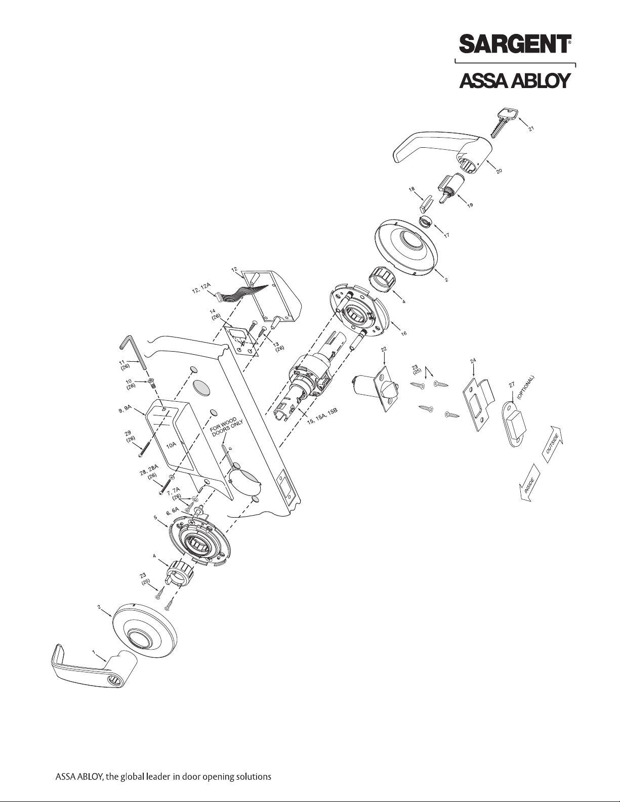
Parts Breakdown
ITEM PART NUMBER DESCRIPTION NO. REQ’D
1
2 *10-0790 Rose scalp "G" 2
2A *10-0798 Rose scalp "L" 2
4
5
6 01-9170 Through-bolt screws 2
6A 10-0802 Plastic screw holder 2
7 01-4388 8 X 1 SELF TAP SCREW 1
A 82-0443 Turn lever cover plate, plastic -black. not shown 1
7
9
9A 52-2400 Controller/circuit board assembly only 1
10 45-1340 Flat head screw (security) 1
0A 52-0069 Battery cover only 1
1
1 01-0297 SOCKET ALLEN SAFETY KEY 1
1
2 *52-2340 Outside escutcheon & keypad 1
1
12A 52-2299 Keypad assembly only 1
13 01-1500 SELF TAP SCREW TYPE "AB" 2
14 52-0033 Fire stop plate and screws 1
15 10-2642 77 Lockbody (std, 10, 21, 23, 30, SC, SE, VA & VS prefixes only) 1
15A 10-2643 77 Lockbody (60, 63, 64 prefixes only) 1
15B 10-2644 77 Lockbody (70, 72, 65-73, 65-73P lockbody) 1
16 10-3049 Outside rose spring assembly (not finished) 1
17 10-0019 Cylinder spacer 1
17A 13-3613 Schlage (SC) cylinder (provide keying details) 1
17B 13-3614 Schlage (SE) cylinder (provide keying details) 1
17C 13-3713 Cylinder (10-Signature) 1
18 10-0312 Cylinder retainer 1
18A 10-0313 Cylinder retainer for removable core, 1
19 13-3266 Cylinder (standard) provide keying details 1
20 *10-2251 “B” Lever outside standard cylinder 1
21 Key (provided with cylinder) A/R
22 *10-2000 2-3/4" Backset latch (standard) 1
22A 10-2053 3-3/4" Backset latch (23 prefix) 1
22B *10-2058 5" Backset latch (25 prefix) 1
22C *10-2634 3/4" Throw (41 prefix) 1
23 01-4414 Screw for standard front and strike 4
24 *08-0312 #800 Strike 1
24A *08-0066 #808 Strike (28-prefix) 1
25 *10-2052 Screw pack- standard (screws (latch, strike, #3) & push pin tool) 1
26 52-2300 Screw pack (includes #’s 7, 11, 13, 14, 28, 28A, 29) 1
27 08-0055 Strike Box- standard 1
28 01-1157 8-32unc-2ax 1 1/4 1
28A 01-9063 WASHER 1
29 01-1119 PH FL HD 8-32 X 1 1/2 1
30 10-0043 Lever Retainer Push Pin, Not Shown 1
*10-0523 “B” Inside lever/regular and 30- 1
10-2204 “J” Inside lever/regular and 30- 1
*
10-0503 “L” Inside lever/regular and 30- 1
*
*10-0547 “P” Inside lever/regular and 30- 1
*10-0536 “B” Inside lever/75 handicap warning 1
10-2247 “J” Inside lever/75 handicap warning 1
*
10-0514 “L” Inside lever /75 handicap warning 1
*
10-0558 “P” Inside lever/75 handicap warning 1
*
10-0792 Spacer bushing 2
10-3048 Inside rose spring assembly (not finished) 1
*10-2875 Inside escutcheon assembly 1
*10-2205 “J” Lever outside standard cylinder 1
*10-0502 “L” Lever outside standard cylinder 1
*10-0546 “P” Lever outside standard cylinder 1
*10-0525 “B” Outside lever/30-competitive cylinder 1
*10-2206 “J” Outside lever/30-competitive cylinder 1
*10-0503 “L” Outside lever/30-competitive cylinder 1
*10-0547 “P” Outside lever/30-competitive cylinder 1
*10-0535 “B” Outside lever/standard cylinder 76 handicap warning 1
*10-2246 “J” Outside lever/standard cylinder 76 handicap warning 1
*10-0513 “L” Outside lever/standard cylinder 76 handicap warning 1
*10-0557 “P” Outside lever/standard cylinder 76 handicap warning 1
10-2070 Screw pack- 28- prefix (screws (front, strike, #3) &push pin tool)
*
ee SARGENT web page for Costal Series Levers.
S
Interchangeable core & Keso
See SARGENT web page for Costal Series Levers.
1
Reproduction in wholeor in part without the express written permissionof SARGENT Manufacturing is prohibited.
12/15/07 © SARGENT Manufacturing Company 2005, 2007. All rights reserved.
8/14/08 Copyright © 2005,2007,2008, SARGENT Manufacturing, an ASSA ABLOY Group company. All rightsreser ved.
*Specify Finish
2
800-810-WIRE (9473) • www.sargentlock.com • A7113E
Page 5
Keypad 10 Line Lock
Parts Breakdown (Continued)
A7113E • 800-810-WIRE (9473) • www.sargentlock.com
3
Reproduction in wholeor in part without the express written permissionof SARGENT Manufacturing is prohibited.
8/14/08 Copyright © 2005,2007,2008, SARGENT Manufacturing, an ASSA ABLOY Group company. All rightsreser ved.
Page 6
Keypad 10 Line Lock
4
Features
KP10G77
• Non volatile memory
• Motor driven, battery operated cylindrical lock
• Battery operated with 4 each “C” Alkaline Batteries
• Low battery alert–4 chirps after code entry
• Option Code available to sound horn every time keypad is pressed
• External remote “request to exit” connector
• External battery input connector included to power unit in event of battery failure
• 100 users total: one Master Code, one Supervisory Code, with the rest being standard codes,
passage codes, or one time only codes
• All programming done at keypad
• Operates utilizing any two to six digits per code. Digits may be repeated and codes may start
with zero
• Minimum 40,000 cycles per set of batteries
• Cylinder override provided
• Entry of three wrong User Codes disables all codes for ten seconds. Green LED flashes
• Piezo horn can be heard with each keystroke or turned off by Master or Supervisory Code
• Last 15 transactions can be output to portable printer via infrared link
Keypad
• Made of ultraviolet stable material
• LED’s indicate valid or invalid entries
• Green LED indicates unlocked. Yellow LED indicates unit is in programming mode
• Flashing green and yellow LED’s indicate lock in passage mode
• Infrared LED for transaction output. Indicates last 15 valid codes
Items included in your KP10G77 Keypad Cylindrical Lock:
• Outside Escutcheon with Keypad
• Motorized Cylindrical Lock with cylinder
• Inside escutcheon with circuit board and battery pack
• Batteries (4 “C”)
• Tools
Reproduction in wholeor in part without the express written permissionof SARGENT Manufacturing is prohibited.
4
12/15/07 © SARGENT Manufacturing Company 2005, 2007. All rights reserved.
8/14/08 Copyright © 2005,2007,2008, SARGENT Manufacturing, an ASSA ABLOY Group company. All rightsreser ved.
800-810-WIRE (9473) • www.sargentlock.com • A7113E
Page 7
Keypad 10 Line Lock
Left Hand
Hinges Left.
Open inward.
“LH”
Left Hand
Reverse Bevel
Hinges Left.
Open Outward
“LHRB”
Right Hand
Hinges Right
Open Inward.
“RH”
Right Hand
Reverse Bevel
Hinges Right.
Open Outward.
“RHRB”
5
Installation Instructions
Step #1 Verify Hand and Bevel of Door
Stand on outside/locked side of the door when determining the door hand
Left hand
hinges left
open inward
LH
Left hand
reverse bevel
hinges left
open outward
LHRB
Right hand
hinges right
open inward
RH
Right hand
reverse bevel
hinges right
open outward
RHRB
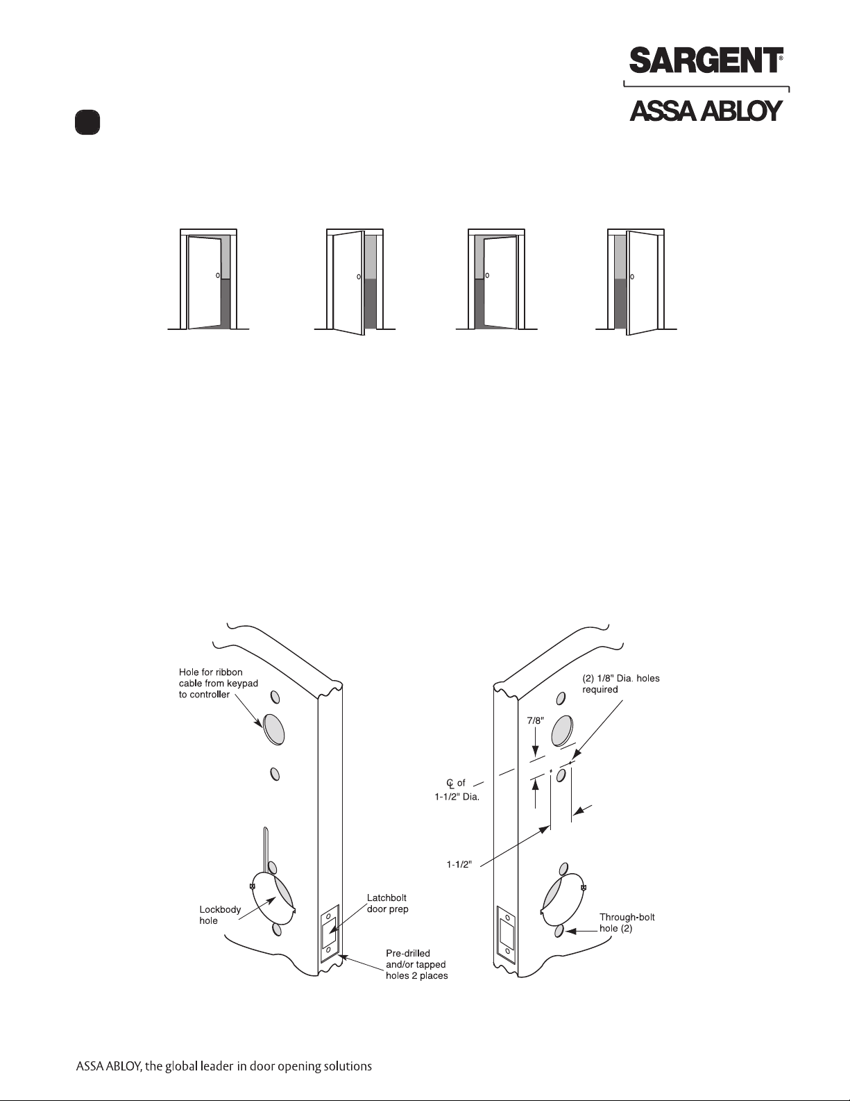
Step #2 Door Preparation
Prepare door according to appropriate template (see website www.sargentlock.com):
• For metal door template, see 4486 and 4494
• For wood door template, see A7332 (scale paper template ships with product) and 4375-1
• Prior to installation, all holes must be free of burrs, debris and sharp edges
• If doors are not properly reinforced per ANSI115.2, commercially available reinforcements
should be installed
Inside of
door
Wood Door Preparation
A7113E • 800-810-WIRE (9473) • www.sargentlock.com
Outside of
door
5
Reproduction in wholeor in part without the express written permissionof SARGENT Manufacturing is prohibited.
8/14/08 Copyright © 2005,2007,2008, SARGENT Manufacturing, an ASSA ABLOY Group company. All rightsreser ved.
Page 8
Keypad 10 Line Lock
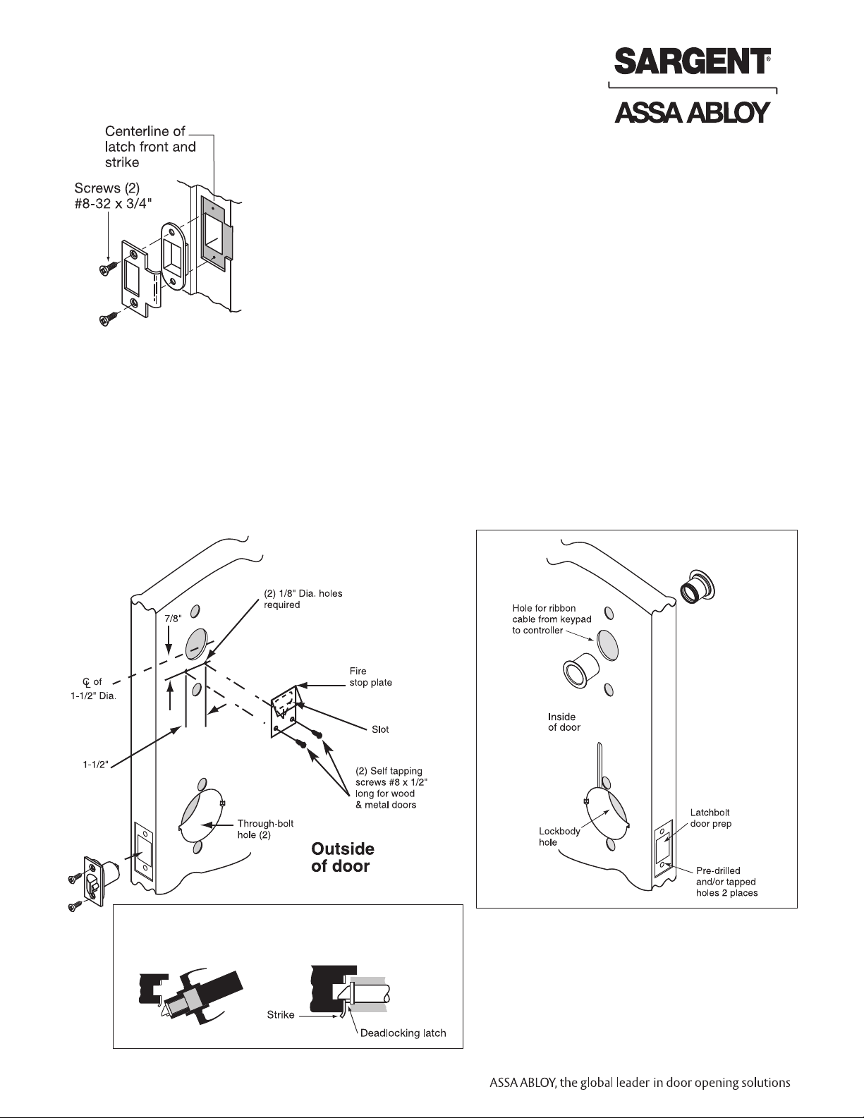
Step #3 Frame Preparation for Strike
Step #4 Latch and Fire Stop Plate Installation
1. Install latch with beveled bolt facing the strike
2. Attach with two screws, but DO NOT tighten completely at this time
3. Attach Fire Stop Plate with two screws
Note: Required for all Fire Rated doors
Fire Rated Doors– Install Fire Stop Plate
(P/N 52-0033) as shown below
Non Fire Rated Exterior Doors–
Install Weather Conduit (P/N 52-2847)
as shown below
Important: Latch bevel must match door
bevel and deadlocking latch must stop on
strike when door is closed
Reproduction in wholeor in part without the express written permissionof SARGENT Manufacturing is prohibited.
6
12/15/07 © SARGENT Manufacturing Company 2005, 2007. All rights reserved.
8/14/08 Copyright © 2005,2007,2008, SARGENT Manufacturing, an ASSA ABLOY Group company. All rightsreser ved.
800-810-WIRE (9473) • www.sargentlock.com • A7113E
Page 9

Keypad 10 Line Lock
Screws partially
tightened
For wood
door only
Inside
of door
1
2
3
1-3/4" thick door
2" thick door
T
hrough-bolt
holes
Rotate to match
through-bolt holes in door
Spacer bushing
Step #5 Lock Installation
Lock Preset to:
• Through-bolt location– 12 & 6 o'clock
• Door thickness– 1-3/4" thick- see below for other door conditions
Adjustment for different through-bolt and door thickness:
• Remove outside lever (usually keyed), scalp and spacer bushing
• Rotate mounting plate to either align with through-bolt holes in door,
or adjust for proper door thicknesses (see markings on through-bolt)
• Reinstall spacer bushing (to align with back of lever) scalp and lever
1. Feed wires into the lock body hole from outside of door
2. Install lock body into cross-bore hole from outside of the door (locked side)
3. Lock body must engage both the latch unit prongs and tail piece (as shown)
IMPORTANT:
Door must remain open
during installation.
Use door stop.
IMPORTANT:
Lockbody
must be
centered in
the door.
A7113E • 800-810-WIRE (9473) • www.sargentlock.com
7
Reproduction in wholeor in part without the express written permissionof SARGENT Manufacturing is prohibited.
8/14/08 Copyright © 2005,2007,2008, SARGENT Manufacturing, an ASSA ABLOY Group company. All rightsreser ved.
Page 10

Keypad 10 Line Lock
Step #6 Securing the Lock to Door
1A. If wood door, feed wires up through
the routed channel as shown
1B. If metal door, feed wire connector within the
door core and out hole on inside of door
2. Attach inside rose assembly and spacer
bushing and secure with screws shown
Step #7 Installation of Outside Escutcheon
• From the outside of the door,
feed keypad wires through fire
stop plate and to the inside of
the door. Lift plate cover if needed.
• IMPORTANT – Fire stop
plate cover must lay flat
before installing the keypad
to avoid interference
Reproduction in wholeor in part without the express written permissionof SARGENT Manufacturing is prohibited.
8
12/15/07 © SARGENT Manufacturing Company 2005, 2007. All rights reserved.
8/14/08 Copyright © 2005,2007,2008, SARGENT Manufacturing, an ASSA ABLOY Group company. All rightsreser ved.
800-810-WIRE (9473) • www.sargentlock.com • A7113E
Page 11

Keypad 10 Line Lock
Step #8 – Security of Outside Escutcheon
• From the inside of the door, use
the #8-32 x 1 1/4” round head
screw with the flat washer to
attach the escutcheon thru the
lower lug
• Straighten escutcheon and tighten
the #8-32 round head screw
Step #9 – Installation of Inside Escutcheon
• Plug the smaller lockbody
wires into the inside
escutcheon. Access holes
vary based on wood or
metal door application
• Plug keypad ribbon
cable connector into
inside escutcheon
IMPORTANT: Both wire
plug connectors go on
only one way. Do not
offset the connectors.
If not seated, keypad
will not function properly
A7113E • 800-810-WIRE (9473) • www.sargentlock.com
9
Reproduction in wholeor in part without the express written permissionof SARGENT Manufacturing is prohibited.
8/14/08 Copyright © 2005,2007,2008, SARGENT Manufacturing, an ASSA ABLOY Group company. All rightsreser ved.
Page 12

Keypad 10 Line Lock
Step #10 Securing of Inside Escutcheon
• Remove black plastic battery cover with security hex wrench (provided)
• Carefully tuck the wire into the routed groove in wood door. The remainder can fit within
bottom portion of escutcheon. Make certain that wires are not pinched by obstructions in escutcheon
• Place inside escutcheon flat against the door
• Secure inside escutcheon with one flat head screw thru interior of inside escutcheon and into
post of exterior escutcheon
• Secure bottom of escutcheon with flat head screw and ferrule
Step #11 Test Lockset
Reproduction in wholeor in part without the express written permissionof SARGENT Manufacturing is prohibited.
• Rotate inside lever
to test for latch
bolt retraction
• Place key into
cylinder and rotate
key for latch
bolt retraction
• Tighten latch
bolt screws on
edge of door
• Test keypad
operation per
manual's
instructions
10
12/15/07 © SARGENT Manufacturing Company 2005, 2007. All rights reserved.
8/14/08 Copyright © 2005,2007,2008, SARGENT Manufacturing, an ASSA ABLOY Group company. All rightsreser ved.
800-810-WIRE (9473) • www.sargentlock.com • A7113E
Page 13

Keypad 10 Line Lock
Step #12 – Battery Installation
• Place (4) C batteries into the compartment as indicated inside escutcheon
• Attach battery cover to inside escutcheon and secure with #8-32 x 3/8" security screw
DO NOT OVER TIGHTEN
How to Remove Outside Lever Only
1.Insert key, rotate 45° clockwise and hold
2.Depress lever retainer with push pin tool (provided)
A7113E • 800-810-WIRE (9473) • www.sargentlock.com
11
Reproduction in wholeor in part without the express written permissionof SARGENT Manufacturing is prohibited.
8/14/08 Copyright © 2005,2007,2008, SARGENT Manufacturing, an ASSA ABLOY Group company. All rightsreser ved.
Page 14

Keypad 10 Line Lock
Washers
(only 30- prefix)
C
ylinder
r
etainer
Cylinder
O
utside
lever
K
ey
C
ylinder
s
pacer
How to Change Cylinder (if required)
1. With outside lever in handuse standard pliers; pull out
cylinder retainer
2. Remove key and cylinder from lever
3. Insert new cylinder
4. Secure by pressing cylinder retainer
flush with shelf*
* NOT SHOWN
6
Programming Instructions
The 10 Line Keypad Lock can support 100 users. Each user is assigned a User Number in addition to
the code used for entry.
Example:
USER USER USER CODE*
TYPE NUMBER (2-6 DIGITS)
Master 01 1 2 3 4
Supervisor 03 3 0 3 0 3 0
Standard 04-97 2 6 5
Special Factory 98
10 Sec. Time Preset 99 1 3 6 8
Reproduction in wholeor in part without the express written permissionof SARGENT Manufacturing is prohibited.
12/15/07 © SARGENT Manufacturing Company 2005, 2007. All rights reserved.
8/14/08 Copyright © 2005,2007,2008, SARGENT Manufacturing, an ASSA ABLOY Group company. All rightsreser ved.
12
800-810-WIRE (9473) • www.sargentlock.com • A7113E
Page 15

Keypad 10 Line Lock
6
Programming Instructions (Continued)
This Keypad 10 Line Lock has 99 User Codes available for programming purposes.
• The Master Code is always User “01”. The Master Code assigns the Emergency and Supervisory Codes.
It is also used for programming. Users are deleted through the Master Programming Code only.
• The Emergency Code is always User “02”. The Emergency Code has an unlock time of 10 seconds.
• The Supervisory Code is always User “03”. The Supervisory Code allows temporary lockout of selected
users, changes duration of unlock time, requests infrared interrogation output, and may add additional
User Codes.
• The first User Code will be User “04” or higher. User numbers do not have to be used or entered
sequentially.
• User codes “98” and “99” have a factory-set unlock time of ten seconds. This allows a handicapped person
extra time which would not be required by other users.
To Begin Programming:
The Keypad 10 Line Lock is preset at the factory with Master Code “1234”. Entering 1234 * will unlock
the lock allowing the lever handle to retract the latchbolt.
Initial Set-Up Procedures:
• The following are typical procedures to follow when setting up your KP10G77 Keypad.
• If a mistake is made during any of procedures, depress the “*” several times until the yellow LED goes out.
• If no keystroke is made in a 30 sec. time frame, the programming up to that point will default and you will
have to start over.
All of the following procedures start with 99#.
If after the last “*” is depressed, the yellow LED does not go out, depress “*” once more.
Change Master Code:
• 1234* (Yellow LED Begins to Blink Slowly) This example uses the Factory Default Master Code
• 50# 1# 01# New Master Code* (Yellow LED Blinks Quickly)
• New Master Code* (Yellow LED Blinks Slowly) *(Yellow LED Goes Out)
To Enter the Emergency Code: (Unlock Duration is Factory Set at 10 Sec)
• Master Code* (Yellow LED Begins to Blink Slowly)
• 50# 1# 02# Emergency Code* (Yellow LED Blinks Quickly)
• Emergency Code* (Yellow LED Blinks Slowly) * (Yellow LED Goes Out)"
To Enter the Supervisory Code:
• Master Code* (Yellow LED Begins to Blink Slowly)
• 50# 1# 03# Supervisory Code* (Yellow LED Blinks Quickly)
• Supervisory Code* (Yellow LED Blinks Slowly) *(Yellow LED Goes Out)
A7113E • 800-810-WIRE (9473) • www.sargentlock.com
13
Reproduction in wholeor in part without the express written permissionof SARGENT Manufacturing is prohibited.
8/14/08 Copyright © 2005,2007,2008, SARGENT Manufacturing, an ASSA ABLOY Group company. All rightsreser ved.
Page 16

Keypad 10 Line Lock
All of the following procedures start with 99# (continued).
If after the last “*” is depressed, the yellow LED does not go out, depress “*” once more.
To Enter a User Code:
• Supervisory or Master Code* (Yellow LED Begins to Blink Slowly)
• 50# 1# User Number (04-97)# User Code* (Yellow LED Blinks Quickly)
• User Code* (Yellow LED Blinks Slowly)* (Yellow LED Goes Out)
To Enter a Passage (Maintained Mode) Code: When Passage Mode is used, the same User Code
must be used to Re-lock the Lock.
• Supervisory or Master Code* (Yellow LED Begins to Blink Slowly)
• 50# 2# User Number (04-97)# User Code* (Yellow LED Blinks Quickly)
• User Code* (Yellow LED Blinks Slowly)* (Yellow LED Goes Out)
To Enter a One Time User Code:
• Supervisory or Master Code* (Yellow LED Begins to Blink Slowly)
• 50# 3# User Number# User Code* (Yellow LED Blinks Quickly)
• User Code* (Yellow LED Blinks Slowly) * (Yellow LED Goes Out)
To Deactivate “Beep” With the Depression of Each Key:
• Supervisory or Master Code* (Yellow LED Begins to Blink Slowly)
• 30# 0# 0# (Yellow LED Continues to Blink Slowly)
• * (Yellow LED Blinks Quickly)
• * (No Beep on Depression and Yellow LED Blinks Slowly)
• * (No Beep on Depression and Yellow LED Goes Out)
To Reactivate “Beep” With the Depression of Each Key:
• Supervisory or Master Code* (Yellow LED Begins to Blink Slowly)
• 30# 0# 1# (Yellow LED Continues to Blink Slowly)
• * (Yellow LED Blinks Quickly)
• * (Beep on Depression and Yellow LED Blinks Slowly)
• * (Beep on Depression and Yellow LED Goes Out)
To Clear the Entire Memory:
• Master Code* (Yellow LED Begins to Blink Slowly)
• 46# 00000# 00000# (Yellow LED Continues to Blink Slowly)
• * (Yellow LED Blinks Quickly)
• * (No Beep on Depression and Yellow LED Goes Out)
• PAUSE, Yellow LED Begins to Blink Again
• * (Yellow LED Goes Out)
Note: This Deletes ALL Codes, including Master, Emergency and Supervisory. The Master Code is set back to
1234, Door Number to 0001 and Unlock time 5 Sec. If the Master Code is not known, Factory Assistance will be
required to clear the memory. 1-800-810-WIRE.
To Program Door Numbers into Keypad:
• Master Code* (Yellow LED Begins to Blink Slowly)
• 43# 0# Door Number# (must be four digits) (Yellow LED Blinks Slowly)
• * (Yellow LED Begins to Blink Quickly)
• * (Yellow LED Blink Slowly)
• * (Yellow LED Goes Out)
Reproduction in wholeor in part without the express written permissionof SARGENT Manufacturing is prohibited.
14
12/15/07 © SARGENT Manufacturing Company 2005, 2007. All rights reserved.
8/14/08 Copyright © 2005,2007,2008, SARGENT Manufacturing, an ASSA ABLOY Group company. All rightsreser ved.
800-810-WIRE (9473) • www.sargentlock.com • A7113E
Page 17

Keypad 10 Line Lock
Sargent also offers a Data Transfer Device (DTD) To Interrogate the lock.
Go to WWW.SARGENTLOCK.COM for information.
All of the following procedures start with 99# (continued).
If after the last “*” is depressed, the yellow LED does not go out,
depress “*” once more.
To Interrogate Transaction Log:
• Supervisory or Master Code* (Yellow LED Begins to Blink Slowly)
• 70# 0# 0# (Yellow LED Blinks Slowly)
• * (Yellow LED Begins to Blink Quickly)
• * (Yellow LED Goes Out)
For additional information, see “Transaction Log”.
Door #5666
Note: Seq. # 1 is the
programming request
to output the entries.
Sequence numbers
2-6 are the actual
entries.
Door
Number
Transaction
Number
Seq User Trans
1 001 003
2 003 001
3 003 001
4 020 001
5 003 001
User
Number
Transaction
type
To Reset / Clear Transaction Log:
• Supervisory or Master Code* (Yellow LED Begins to Blink Slowly)
• 76# 00000# 00000# (Yellow LED Blinks Slowly)
• * (Yellow LED Begins to Blink Quickly)
• * (Yellow LED Goes Out)
Hold an infrared printer up to the
red infrared LED (as shown). An
HP82240B Infrared Printer can
be used to download information
from the keypad to a printout.
To Delete a User Number:
• Master Code* (Yellow LED Begins to Blink Slowly)
• User Number# (Yellow LED Blinks Slowly)
• * (Yellow LED Begins to Blink Quickly)
• * (Yellow LED Blinks Slowly)
• * (Yellow LED Goes Out)
To Disable / Enable a User Number:
• Supervisory or Master Code* (Yellow LED Begins to Blink Slowly)
• 56# 0# = Enable, 1# = Disable, User Number# (04-99) (Yellow LED Blinks Slowly)
• * (Yellow LED Begins to Blink Quickly)
• * (Yellow LED Blinks Slowly)
• * (Yellow LED Goes Out)
To Set Unlock Time:
• Master Code* (Yellow LED Begins to Blink Slowly)
• 85# Time Duration# (01-99 Sec) 0# (Yellow LED Blinks Slowly)
• * (Yellow LED Begins to Blink Quickly)
• * (Yellow LED Blinks Slowly)
• * (Yellow LED Goes Out)
Note: The Unlock Time is Adjustable for Momentary Operation. A 5 second unlock time is recommended to
extend battery life. Once the unlock time is entered, it is the same for ALL users except 02, 98 and 99 which are
factory set for 10 seconds.
Reproduction in wholeor in part without the express written permissionof SARGENT Manufacturing is prohibited.
A7113E • 800-810-WIRE (9473) • www.sargentlock.com
15
8/14/08 Copyright © 2005,2007,2008, SARGENT Manufacturing, an ASSA ABLOY Group company. All rightsreser ved.
Page 18

Keypad 10 Line Lock
Chain Programming
When programming multiple User Numbers and Codes into the
10 Line Keypad Lock, it is not necessary to leave and re-enter the
programming mode (50) for each entry. Multiple entries may be chained
together and the three different types of user codes (Standard, Passage
and One Time) may be mixed.
The format to be used is as follows where:
“T” is the Type of user code with “1” Standard, “2” Passage and “3” One Time.
“UN_” is User Number (04-99)
“UC_” is User Code (2 to 6 digits) which correlates with the User Number 99# Master or Supervisor
Code* 50# Type# User Number a# User Code a*
User Code a* T# UNb# UCb* UCb* T# UNc# UCc* UCc* ...... T# UN_# UC_* UC_**
An example with four user codes is shown below:
Type User Number User Code
1 05 875
3 12 2226
2 08 5444
1 50 3367
Using Master Code 4732 and above information, the lock would be programmed as follows:
99# 4732* 50# 1# 05# 875* 875* 3# 12# 2226* 2226* 2# 08# 5444* 5444* 1# 50# 3367*
3367**
If all user codes are the same type, it is not necessary to enter the type number with each
entry. The type number has to be entered with the first user code only.
The format now simplifies to:
99# Master or Supervisor Code* 50# Type# User Number a# User code a* User Code a*
UNb# UCb* UCb* UNc# UCc* UCc*....... UN_# UC_* UC_**
An example with three user codes is shown below:
Type User Number User Code
1 07 77
1 15 67832
1 91 7568
Using Master Code 45988 and above information, the lock would be programmed as follows:
99# 45988* 50# 1# 07# 77* 77* 15# 67832* 67832* 91# 7568* 7568**
To chain the User Number delete procedure:
99# Master Code* User Number a#** UNb#** UNc#**....... UN_#****
Using the information from the above example:
99# 45988* 07#** 15#** 91#****
Reproduction in wholeor in part without the express written permissionof SARGENT Manufacturing is prohibited.
16
12/15/07 © SARGENT Manufacturing Company 2005, 2007. All rights reserved.
8/14/08 Copyright © 2005,2007,2008, SARGENT Manufacturing, an ASSA ABLOY Group company. All rightsreser ved.
800-810-WIRE (9473) • www.sargentlock.com • A7113E
Page 19

Keypad 10 Line Lock
To output the last 15 entries, enter 99 # Supervisory or Master Code * 70 # 0 # 0 # **.
Note: Seq. # 1 is the
programming request to output
7
Transaction Log
Door Number
• 4 Digits
• Up to 9999 different doors, assigned by user
Transaction Number
• Single digit - 1-6
• Latest transaction - 1
• Oldest transaction - 6
User Number
• Three digits - 001 through 099
• User numbers assigned at time of programming
Transaction Types
• 001 =Access granted
• 003 = Log printed
Optional Equipment
Door
Number
Transaction
Number
the entries. Sequence numbers
2-6 are the actual entries.
Door #5666
Seq User Trans
1 001 003
2 003 001
3 003 001
4 020 001
5 003 001
Hold an infrared printer up to the
red infrared LED (as shown). An
HP82240B Infrared Printer can
be used to download information
from the keypad to a printout.
User
Number
Transaction
type
• Printer Paper (6 Rolls) - 52-0034 used for infrared printers
• Auxiliary Power Unit (APU) 52-2065 - used to unlock unit if
batteries are too weak and cylinder is not used.
• Infrared Printer - 52-2069 - used to download the user and
transaction type.
• Remote Unlocking - 52-2071 - used for remote unlocking
of keypad 10 Line Lock. When remote unlocking feature is
used, the latchbolt can be retracted by turning the lever
handle. Use a QC2A Hinge.
ElectroLynx
As part of their promise to provide innovative, fast and effective high
security solutions to their customers, ASSA ABLOY Group companies
offer ElectroLynx
electrification of the door opening.
ElectroLynx
®
®
, a universal quick-connect system that simplifies the
®
is a registered trademark of ASSA ABLOY Inc.
Remote
unlocking
connector
placement
TB-2
A7113E • 800-810-WIRE (9473) • www.sargentlock.com
17
Reproduction in wholeor in part without the express written permissionof SARGENT Manufacturing is prohibited.
8/14/08 Copyright © 2005,2007,2008, SARGENT Manufacturing, an ASSA ABLOY Group company. All rightsreser ved.
Page 20

Keypad 10 Line Lock
Serrure à clavier KP10G77
Guide de programmation
La serrure à clavier KP10G77 peut accomoder 100 utilisateurs. On doit assigner à chacun un numéro
d’utilisateur, en plus de son code d’entrée.
Example:
Type d’usager Numéro d’usager Code d’usager
(2 à 6 chiffres)
Maître 01 1 2 3 4
Urgence 02 2 2 2 2 2
Superviseur 03 3 0 3 0 3 0
Ordinaire 04 à 97 2 6 5
Spécial usine 98
10 secondes 99 1 3 6 8
99 codes d’utilisateurs disponibles à la programmation
• Le code maître est toujours l’utilisateur programmation. Les utilisateurs sont
• Le code d’urgence est toujours l’utilisateur temps de déverrouillage de 10 secondes.
• Le code superviseur est toujours modification du temps de déverrouillage,
• Le premier code d’utilisateur sera
• Les codes ‘’98’’ et ‘’99’’ établis en les personnes handicapées.
Reproduction in wholeor in part without the express written permissionof SARGENT Manufacturing is prohibited.
18
8/14/08 Copyright © 2005,2007,2008, SARGENT Manufacturing, an ASSA ABLOY Group company. All rightsreser ved.
800-810-WIRE (9473) • www.sargentlock.com • A7113E
Page 21

Keypad 10 Line Lock
Pour commencer :
Le code maître établi en usine est “1234’’. Appuyer sur 1234* déverrouille la serrure, permettant au
levier de retirer le pêne.
Codification initiale :
Dans une séquence typique de programmation, le voyant jaune clignotera doucement après l’entrée
du code maître ou superviseur suivi de “ * ”. Il continuera jusqu’à l’entrée du nouveau code suivi de
“ * ”. Il clignotera ensuite rapidement jusqu’à l’entrée de “ * ”. Si le voyant reste allumé, sans clignoter,
durant la programmation, il y a eu une erreur de programmation et la séquence doit être
recommancée.
Pour changer le code maître
Entrer : 99 # 1234 * 50 # 1 # 01 # Nouveau code maître suivi de * Nouveau code maître suivi de * *
Pour entrer le code d’urgence :
Entrer : 99 # Code maître suivi de * 50 # 1 # 02 # Code d’urgence * Code d’urgence * *
Remarque : La durée de déverrouillage est réglée en usine à 10 secondes.
Pour entrer le code superviseur :
Entrer : 99 # Code maître suivi de * 50 # 1 # 02 # Code d’urgence * Code d’urgence * *
Entrer : 99 # Code maître suivi de * 50 # 1 # 03 # Code superviseur suivi de * Code superviseur suivi de * *
Pour entrer un code d’utilisateur :
Entrer : 99 # Code maître ou superviseur suivi de * 50 # 1 # Code d’utilisateur (entre 04 et 97) suivi du
# et du code d’utilisateur suivi de * Code d’utilisateur suivi de *
Pour entrer un code passage (fonction maintenue) :
Entrer : 99 # Code maître ou superviseur suivi de * 50 # 2 # Numéro d’utilisateur (entre 04 et 97) suivi
du # et code d’utilisateur suivi de * Code d’utilisateur suivi de * *
Le même code devra être utilisé pour reverrouiller la serrure.
A7113E • 800-810-WIRE (9473) • www.sargentlock.com
19
Reproduction in wholeor in part without the express written permissionof SARGENT Manufacturing is prohibited.
8/14/08 Copyright © 2005,2007,2008, SARGENT Manufacturing, an ASSA ABLOY Group company. All rightsreser ved.
Page 22

Keypad 10 Line Lock
Pour entrer un code servant une fois seulement :
Entrer : 99 # Code maître ou superviseur suivi de * 50 # 3 # Numéro
d’utilisateur suivi du # et code d’utilisateur suivi de * Code d’utilisateur suivi
de * *
Pour annuler la tonalité entendue en appuyant sur les touches :
Entrer : 99 # Code maître ou superviseur suivi de * 30 # 0 # 0 # * * *
Pour remettre la tonalité entendue en appuyant sur les touches :
Entrer : 99 # Code maître ou superviseur suivi de * 30 # 0 # 1 # * * *
Pour effacer entièrement la mémoire :
Entrer : 99 # Code maître suivi de * 46 # 00000 # 00000 # * * <PAUSE> *
Remarque : Ceci annule tous les codes, incluant les codes maître et superviseur.
Le code maître redevient 1234, le numéro de porte 0001 et le temps de déverrouillage 5 secondes.
Pour programmer les numéros de porte :
Entrer : 99 # Code maître suivi de * 43 # 0 # Numéro de porte (doit être quatre chiffres) suivi de # * * *
Pour lire le rapport des activités :
Entrer : 99 # Code maître ou superviseur suivi de * 70 # 0 # 0 # * *
Pour effacer le rapport des activités :
Entrer : 99 # Code maître suivi de * 76 # 00000 # 00000 # * *
Remarque : Après chaque programmation, le voyant jaune devrait arrêter de clignoter.
S’il clignote toujours après la dernière * , appuyer de nouveau sur *.
Pour annuler un numéro d’utilisateur :
Entrer : 99 # Code maître suivi de * Numéro d’utilisateur suivi de # * * * *
Pour annuler un numéro d’utilisateur :
Entrer : 99 # Code maître suivi de * Numéro d’utilisateur suivi de # * * * *
Pour invalider et réactiver un numéro d’utilisateur :
Entrer : 99 # Code maître ou superviseur suivi de * 56 # choix # numéro d’utilisateur (04 à 99) suivi de # * *
A noter : choix 0 = réactive, 1 = invalide,
Reproduction in wholeor in part without the express written permissionof SARGENT Manufacturing is prohibited.
20
8/14/08 Copyright © 2005,2007,2008, SARGENT Manufacturing, an ASSA ABLOY Group company. All rightsreser ved.
800-810-WIRE (9473) • www.sargentlock.com • A7113E
Page 23

Keypad 10 Line Lock
Pour fixer le temps de déverrouillage :
Entrer : 99 # Code maître suivi de * 85 # Durée suivie de # 0 # * * *
Remarque : Le temps de déverrouillage est réglable entre 01 et 99 secondes. On recommande 5
secondes pour prolonger la durée des piles. Le temps sera le même pour TOUS les utilisateurs, sauf
02, 98 et 99 qui sont pré-réglés en usine à 10 secondes.
Programmation en chaîne
Pour programmer des numéros et des codes d’utilisateurs multiples, il n’est pas nécessaire de quitter
le mode de programmation (50) entre chaque entrée. On peut entrer un après l’autre, en désordre, les
trois différents types de codes d’utilisateurs (ordinaire, passage et une fois).
Le format à suivre est le suivant :
‘’T’’ est le type de code d’usager, soit ‘’1’’ pour ordinaire, ‘’2’’ pour passage et ‘’3’’ pour une fois.
‘’UN_’’ est le numéro d’utilisateur (entre 04 et 99)
‘’UC_’’ est le code d’utilisateur (de 2 à 6 chiffres) qui correspond au numéro d’utilisateur.
99# Code maître ou superviseur * 50# Type# Numéro d’utilisateur a# Code d’utilisateur a *
Code d’utilisateur a * T# Unb# Ucb * Ucb * T# Unc# Ucc * Ucc * ..... T# UN_# UC_ * UC_ **
Ceci est un exemple de quatre codes d’utilisateurs :
Type Numéro d’utilisateur Code d’utilisateur
1 05 875
3 12 2226
2 08 5444
1 50 3367
En utilisant le code maître 4732 et les renseignements ci-dessus, la programmation de la serrure serait
la suivante :
99# 4732* 50# 1# 05# 875* 875* 3# 12# 2226* 2226*
2# 08# 5444* 5444* 1# 50# 3367* 3367**
A7113E • 800-810-WIRE (9473) • www.sargentlock.com
21
Reproduction in wholeor in part without the express written permissionof SARGENT Manufacturing is prohibited.
8/14/08 Copyright © 2005,2007,2008, SARGENT Manufacturing, an ASSA ABLOY Group company. All rightsreser ved.
Page 24

Keypad 10 Line Lock
Il n’est pas nécessaire d’entrer le numéro de type à chaque entrée si tout les codes d’utilisateurs sont
du même type. Le numéro de type doit être entré avec le premier code d’utilisateur seulement.
Le format sera donc simplifié:
99# Code maître ou superviseur* 50# Type# Numéro d’utilisateur a#
Code d’utilisateur a* Code d’utilisateur a* Unb# Ucb* Ucb* Unc#
Ucc* Ucc* ..... UN_# UC_* UC_**
Ceci est un exemple de trois codes d’utilisateurs :
Type Numéro d’utilisateur Code d’utilisateur
1 07 77
1 15 67832
1 91 7568
En utilisant le code maître 45988 et les renseignements ci-dessus, la programmation de la serrure sera
la suivante :
99# 45988* 50# 1# 07# 77* 77* 15# 67832* 67832* 91# 7568* 7568**
Pour annuler en chaîne les numéros d’usagers :
99# Code maître * Numéro d’utilisateur a#** Unb#** Unc#** ... UN_#****
En utilisant les renseignements de l’exemple ci-dessus :
99# 45988* 07#** 15#** 91#****
A T T E N T I O N
Bien vérifier le branchement entre le clavier extérieur et la plaque du
côté intérieur de la porte. Toutes les broches doivent être bien en
place pour que le clavier fonctionne. Voir étape 6A du manuel
illustré.
Reproduction in wholeor in part without the express written permissionof SARGENT Manufacturing is prohibited.
22
8/14/08 Copyright © 2005,2007,2008, SARGENT Manufacturing, an ASSA ABLOY Group company. All rightsreser ved.
800-810-WIRE (9473) • www.sargentlock.com • A7113E
Page 25

Keypad 10 Line Lock
To output the last 15 entries, enter 99 # Supervisory or Master Code * 70 # 0 # 0 # **.
Note: Seq. # 1 is the
7
Transaction Log
Door Number
• 4 Digits
• Up to 9999 different doors, assigned by user
Transaction Number
• Single digit - 1-6
• Latest transaction - 1
• Oldest transaction - 6
User Number
• Three digits - 001 through 099
• User numbers assigned at time of programming
Transaction Types
• 001 =Access granted
• 003 = Log printed
Optional Equipment
Door
Number
Transaction
Number
programming request to output
the entries. Sequence numbers
2-6 are the actual entries.
Door #5666
Seq User Trans
1 001 003
2 003 001
3 003 001
4 020 001
5 003 001
User
Number
Hold an infrared printer up to the
red infrared LED (as shown). An
HP82240B Infrared Printer can
be used to download information
from the keypad to a printout.
Transaction
type
• Printer Paper (6 Rolls) - 52-0034 used for infrared printers
• Auxiliary Power Unit (APU) 52-2065 - used to unlock unit if
batteries are too weak and cylinder is not used.
• Infrared Printer - 52-2069 - used to download the user and
transaction type.
• Remote Unlocking - 52-2071 - used for remote unlocking
of keypad 10 Line Lock. When remote unlocking feature is
used, the latchbolt can be retracted by turning the lever
handle.
Remote
unlocking
connector
placement
A7113E • 800-810-WIRE (9473) • www.sargentlock.com
23
Reproduction in wholeor in part without the express written permissionof SARGENT Manufacturing is prohibited.
8/14/08 Copyright © 2005,2007,2008, SARGENT Manufacturing, an ASSA ABLOY Group company. All rightsreser ved.
Page 26

Founded in the early 1800s, SARGENT®is a market leader in locksets, cylinders, doorclosers, exit devices,
electro-mechanical products and access control systems for newconstruction, renovation, and replacement applications.
The company’s customer base includes commercialconstruction, institutional, and industrial markets.
Copyright © 2005,2007,2008, SARGENT Manufacturing, an ASSA ABLOY Group company. All rightsreser ved.
Reproduction in wholeor in part without the express written permissionof SARGENT Manufacturing is prohibited.
ASSA ABLOYis the global leader in dooropening solutions, dedicated to
satisfying end-user needs forsecurit y, safety and convenience.
A7113E-8/08
 Loading...