

Sargent IN220 Installation Instructions Manual
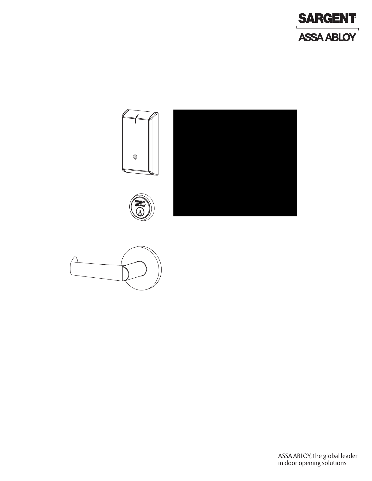
IN220
PoE
Mortise Lock
Installation Instructions
A8204B
04/16
Copyright 2016, Sargent Manufacturing Company, an ASSA ABLOY Group company.
All rights reserved. Reproduction in whole or in part without the express written
permission of Sargent Manufacturing Company is prohibited.

Table of Contents
1
Warning ...................................................................................3
2
General Description .................................................................4
3
Specifications ..........................................................................4
4
System Overview .....................................................................4
5
Parts Breakdown .....................................................................5
Installation Wiring ...................................................................7
6
7
Lock Installation ....................................................................11
8
Operational Check ................................................................25
1
Warning
FCC:
This equipment has been tested and found to comply with the limits for a Class B digital device, pursuant to Part 15 of the
FCC Rules. These limits are designed to provide reasonable protection against harmful interference in a residential installation.
This equipment generates, uses, and can radiate radio frequency energy and, if not installed and used in accordance with the
instructions, may cause harmful interference to radio communications. However, there is no guarantee that interference will not
occur in a particular installation. If this equipment does cause harmful interference to radio or television reception, which can be
determined by turning the equipment off and on, the user is encouraged to try to correct the interference by one or more of the
following measures:
• Reorient or relocate the receiving antenna.
• Increase the separation between the equipment and receiver.
• Connect the equipment into an outlet on a circuit different from that to which the receiver is connected.
• Consult the dealer or an experienced radio/TV technician for help.
Changes or modifications to this device not expressly approved by ASSA ABLOY
could void the user’s authority to operate the equipment.
Industry Canada:
This Class B digital apparatus meets all requirements of the Canadian Interference Causing Equipment Regulations. Operation is
subject to the following two conditions: (1) this device may not cause harmful interference, and (2) this device must accept any
interference received, including interference that may cause undesired operation.
Cet appareillage numérique de la classe B répond à toutes les exigences de l’interférence canadienne causant des règlements
d’équipement. L’opération est sujette aux deux conditions suivantes: (1) ce dispositif peut ne pas causer l’interférence nocive, et (2)
ce dispositif doit accepter n’importe quelle interférence reçue, y compris l’interférence qui peut causer l’opération peu désirée.
“This equipment complies with FCC radiation exposure limits set forth for an uncontrolled environment. This equipment should be
installed and operated with minimum distance 20cm between the radiator and your body. This transmitter must not be co-located
or operating in conjunction with any other antenna or transmitter.”
Under Industry Canada regulations, this radio transmitter may only operate using an antenna of a type and maximum (or lesser)
gain approved for the transmitter by Industry Canada. To reduce potential radio interference to other users, the antenna type and
its gain should be so chosen that the equivalent isotropically radiated power (e.i.r.p.) is not more than that necessary for successful
communication.
Conformément à la réglementation d’Industrie Canada, le présent émetteur radio peut fonctionner avec une antenne d’un type et
d’un gain maximal (ou inférieur) approuvé pour l’émetteur par Industrie Canada. Dans le but de réduire les risques de brouillage
radioélectrique à l’intention des autres utilisateurs, il faut choisir le type d’antenne et son gain de sorte que la puissance isotrope
rayonnée équivalente (p.i.r.e.) ne dépasse pas l’intensité nécessaire à l’établissement d’une communication satisfaisante.
Any retrofit or other field modification to a fire rated opening can potentially impact the fire rating of the opening, and SARGENT
Manufacturing makes no representations or warranties concerning what such impact may be in any specific situation. When
retrofitting any portion of an existing fire rated opening, or specifying and installing a new fire-rated opening, please consult with a
!
code specialist or local code official (Authority Having Jurisdiction) to ensure compliance with all applicable codes and ratings.
To avoid possible damage from electrostatic discharge (ESD), some basic precautions should be used when
handling electronic components:
Copyright © 2016, Sargent Manufacturing Company, an ASSA ABLOY Group company. All rights reserved.
Reproductions in whole or in part without express written permission of Sargent Manufacturing Company is prohibited.
04/30/16
1-800-810-WIRE • www.sargentlock.com • A8204B
• Minimize build-up of static by touching and/or maintaining contact with unpainted metal surfaces
such as door hinges, latches, and mounting plates especially when mounting electronic components such
as readers and controllers onto the door.
• Leave components (reader and controller) protected in their respective anti-static bags until ready
for installation
• Do not touch pins, leads or solder connections on the circuit boards
IN220 Mortise Lock
2
General Description
The SARGENT IN220 Mortise lock combines superior aesthetics with the energy efficiency and
streamlined architecture of Power-over-Ethernet (PoE) access control. PoE-enabled access control
allows facilities to leverage existing network infrastructure for enhanced security and easier, more
cost-effective installations. Featuring multiCLASS SE® technology, it supports multiple credential
types, including mobile devices, for a future-proof solution that is convenient and secure.
3
Hardware Specifications
• Complete lockset with on-board memory
• ADA compliant
• Easily retrofits existing door preps (mortise)
• Latch - Stainless steel
• Optional deadbolt - Hardened steel
• Guardbolt - Stainless steel, non handed
• Handing (RH/RHR/LH/LHR) must be specified,
but is easily field-reversible without opening
lock case
• Case - 12 gauge heavy duty wrought steel
• Cylinder retracts latchbolt (and deadbolt)
• Lock furnished for 1-3/4” doors.
For other thicknesses, consult factory.
• Outside lever controlled by any combination of
contactless reader or mechanical cylinder
• Inside lever retracts both latch and deadbolt
• May be used for indoor and outdoor applications
• ANSI/BHMA A156.25 Listed Grade 1 Compliant
NOTE: A weather-protective gasket is required for outdoor applications.
4
Electronic Specifications
• HID® multiCLASS SE® technology offers support for
the following credentials:
• 2.4 GHz credential compatibility:
• Secure Identity Object™ (SIO) on Mobile IDs
(Bluetooth Smart)
• 13.56 MHz credential compatibility:
• iCLASS®
• iCLASS SE® (SIO-enabled)
• iCLASS Seos
• SIO on MIFARE® Classic
• SIO on MIFARE® DESfire® EV1
• MIFARE® Classic
• DESfire® EV1
• NFC-enabled mobile phones
• 125 kHz credential compatibilty:
• HID Prox
®
®
• Input Power: PoE Class 1 Device, as defined by
IEEE 802.3af, requires less than to 3.84 watts
over structured cabling
• Multiple time zone and holiday access scheduling
• First-in unlock or automatic unlock configuration
based on specified time schedule
• 2,400 users per lock; 10,000 event audit trail
• Power Requirements: 55VDC, 90mA
• Privacy button
• UL Listed* - UL 294 Indoor Use
• CUL Listed - S319: Class 1
• UL 294 Access Control Ratings:
Destructive Attack Level 1
Line Security Level 1
Endurance Level 4
Standby Power Level 1
*UL testing was conducted on product powered by
UL Listed model 9001GR/AC injector; manufactured
by Microsemi Corp.
Copyright © 2016, Sargent Manufacturing Company, an ASSA ABLOY Group company. All rights reserved.
Reproductions in whole or in part without express written permission of Sargent Manufacturing Company is prohibited.
04/30/16
4 1-800-810-WIRE • www.sargentlock.com • A8204B
IN220 Mortise Lock
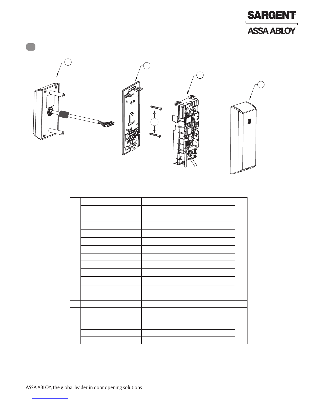
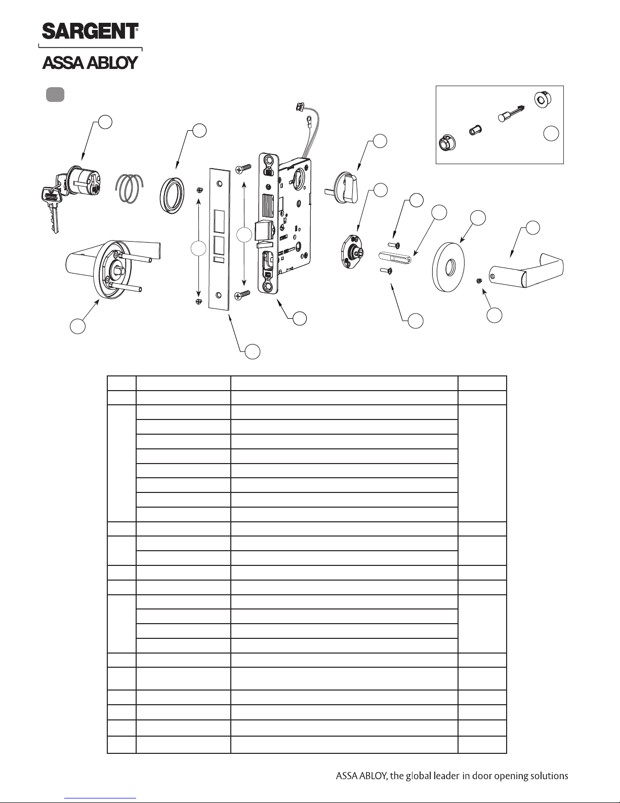
5
Parts Breakdown
1*
2
3
4
2a
PART NO./ORDER
ITEM
1 IN-220-EM01-[B*]IP-B Reader assembly - black plastic 1
STRING
IN-220-EM01-[B*]IP-W Reader assembly - white plastic
DESCRIPTION
QTY.
IN-220-EM01-[B*]IP-MB-xxx** Reader assembly - black plastic with metal trim
IN-220-EM01-[B*]IP-MW-xxx** Reader assembly - white plastic with metal trim
IN-220-EM01-[B*]IPS-B Reader assembly - black plastic
IN-220-EM01-[B*]IPS-W Reader assembly - white plastic
IN-220-EM01-[B*]CP-B Reader assembly - FeliCa - black plastic
IN-220-EM01-[B*]CP-W Reader assembly - FeliCa - white plastic
IN-220-EM01-[B*]CP-MB-xxx** Reader assembly - FeliCa - black plastic with metal trim
IN-220-EM01-[B*]CP-MW-xxx** Reader assembly - FeliCa - white plastic with metal trim
IN-220-EM01-[B*]IPS-MB-xxx** Reader assembly - black plastic with metal trim
IN-220-EM01-[B*]IPS-MW-xxx** Reader assembly - white plastic with metal trim
2 IN-220-EM04 Mounting plate assembly 1
2a Through-bolts (#8-32 x 1 1/4”) 2
3 IN-220-EM03 Controller assembly 1
4 IN-220-EM02-B Inside cover assembly - black plastic 1
IN-220-EM02-W Inside cover assembly - white plastic
IN-220-EM02-MB-xxx** Inside cover assembly - black plastic with metal trim
IN-220-EM02-MW-xxx** Inside cover assembly - white plastic with metal trim
*Specifying B indicates Bluetooth® Smart option when ordering
** Specify finish
Copyright © 2016, Sargent Manufacturing Company, an ASSA ABLOY Group company. All rights reserved.
Reproductions in whole or in part without express written permission of Sargent Manufacturing Company is prohibited.
1-800-810-WIRE • www.sargentlock.com • A8204B 5
04/30/16
5
Parts Breakdown (Continued)
IN220 Mortise Lock
1
2
4
9
5
5
5
10
6
7
10
11
ITEM
1 Consult Factory #41 Mortise cylinder 1
2 Consult Factory Cylinder Rosette 1
3 IN-220-7976-hand-fin Lock body with deadbolt with cylinder 1
4 Consult Factory Turn lever 1
5 82-3211 Trim Pack - 8200 Standard levers 1
6 Consult Factory Rose
7 Consult Factory Inside lever 1
8 79-0035 Lock front - 7900 - Without deadbolt 1
9 52-5373 Door Position Switch (DPS) Pack** -not required for 8200 1
10 77-4236 Mortise screw pack - specify finish (includes: wood and metal lock
11 Consult Factory Outside trim 1
12 A8150 Field prep template (not shown) 1
Copyright © 2016, Sargent Manufacturing Company, an ASSA ABLOY Group company. All rights reserved.
Reproductions in whole or in part without express written permission of Sargent Manufacturing Company is prohibited.
13 4713 Door manufacturers template (not shown) 1
14 A8204B Instructions (this manual) 1
STRING
IN-220-7977-hand-fin Lock body with deadbolt without cylinder
IN-220-7978-hand-fin Lock body without deadbolt with cylinder
IN-220-7979-hand-fin Lock body without deadbolt without cylinder
IN-220-82276-hand-fin Lock body with deadbolt with cylinder (not shown)
IN-220-82277-hand-fin Lock body with deadbolt without cylinder (not shown)
IN-220-82278-hand-fin Lock body without deadbolt with cylinder (not shown)
IN-220-82279-hand-fin Lock body without deadbolt without cylinder (not shown)
82-5357 Trim Pack - 8200 Deco Levers & 7900 all lever styles (shown)
79-0036 Lock front - 7900 - With deadbolt (shown)
82-0578 Lock front - 8200 - Without deadbolt
82-0579 Lock front - 8200 - With deadbolt
PART NO/ORDER
8
body screws, faceplate screws, and strike screws)
3
DESCRIPTION QTY
5
5
1
04/30/16
6 1-800-810-WIRE • www.sargentlock.com • A8204B

IN220 Mortise Lock
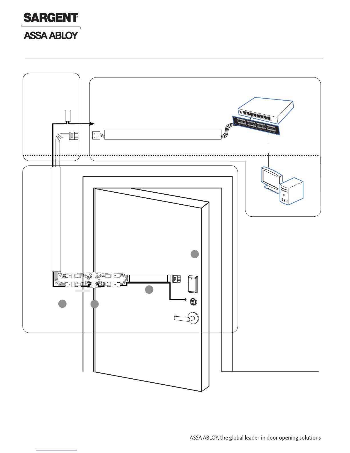
6
Installation Wiring
Overview
SARGENT IN220 PoE Typical Application
Network Cable
Surface Mount RJ45
Network Switch (802.3af)
LMT: Lock Management Tool
A. PoE frame harness assembly
B. PoE data hinge from McKinney
C. PoE door harness* from McKinney
D. IN220 PoE Lock
E. DPS: Door Position Switch
(Needed on Cylindrical and Exits only)
* Door width determines length
A
B
C
E
D
1-800-810-WIRE • www.sargentlock.com • A8204B 7
Copyright © 2016, Sargent Manufacturing Company, an ASSA ABLOY Group company. All rights reserved.
Reproductions in whole or in part without express written permission of Sargent Manufacturing Company is prohibited.
04/30/16
Installation Wiring (Continued)
IN220 Mortise Lock
Supplied by CI
Crimp Connector
Ceiling
24AWG
Stranded
Drain
Wire for
Earth
Ground in
15' Frame
Harness
Frame-Side
Harness
Assembly
(15' length)
Cable drain wire
concealed in
shrink tubing
B-Splice
RJ45-M
24 AWG, 100ohm
Cable: Cat 5e or higher
Molex-M
Molex-F
A
Certified Integrator (CI) supplies and terminates
the B-Splice connector and the
male RJ45 connector from harness to
end user provided facility cable
To building or electrical ground
RJ45-F Jack
Cable: Cat 5e or higher
24 AWG
Cable: Cat 5e,
Molex-F
B
Molex-M
26 AWG stranded,
100ohm
C
Ring Terminal
Secured to Lock
Mounting Plate
RJ45-M
Ground
Patch Cable
Patch Panel to
PoE Switch
D
PoE
Lock
Supplied by End User
PoE Switch
PoE Switch is
Terminated to
Earth Ground
Patch Panel
Drain Wire Terminated on Rack
Approved Software
Notes:
• Connectors go on only
one way. They cannot
be placed in an incorrect
position.
• Do not force and do not
offset connectors
• Be sure they are
completely seated (flush)
• PoE power source
cannot be connected to
a receptacle controlled
by a switch
Wiring to TIA/EIA 568-B Standard
Copyright © 2016, Sargent Manufacturing Company, an ASSA ABLOY Group company. All rights reserved.
Reproductions in whole or in part without express written permission of Sargent Manufacturing Company is prohibited.
04/30/16
8 1-800-810-WIRE • www.sargentlock.com • A8204B
IN220 Mortise Lock
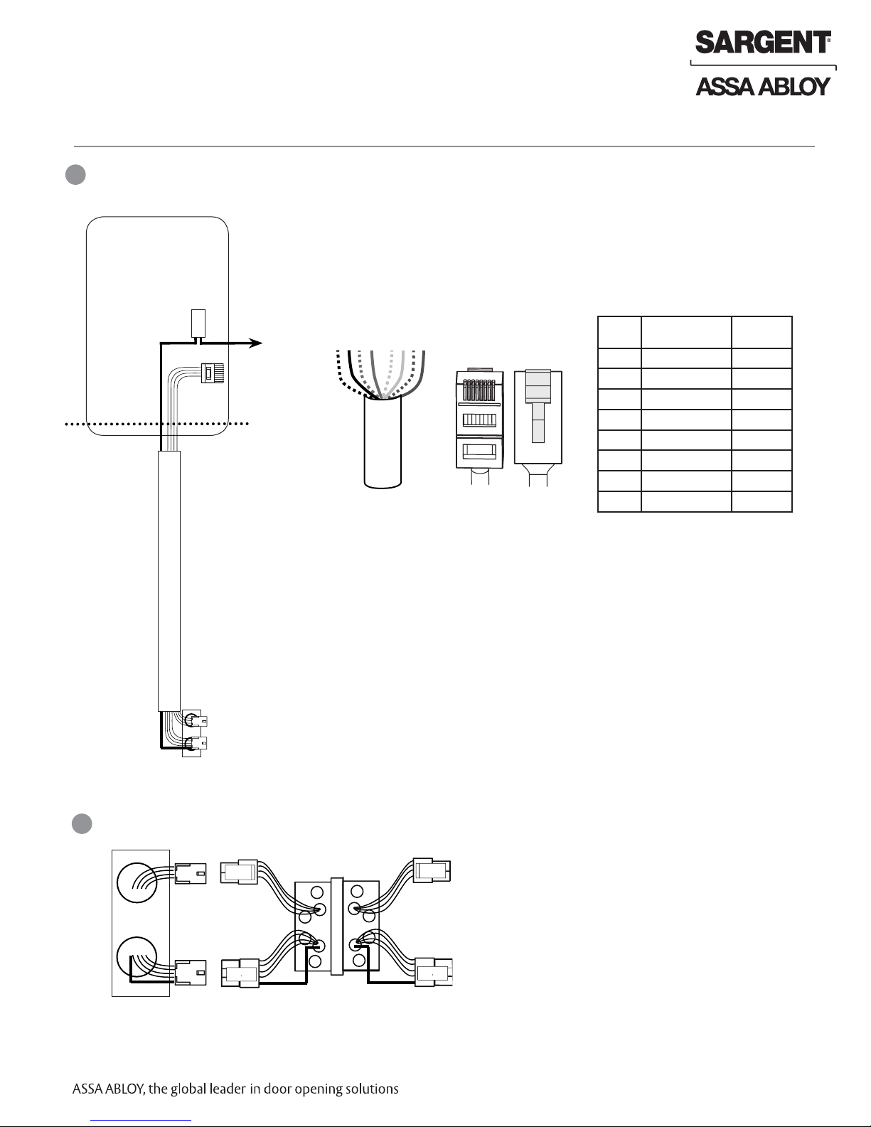
Installation Wiring (Continued)
A
Frame Harness Installation
Supplied by CI
Crimp Connector
Ceiling
24AWG
Stranded
Drain
Wire for
Earth
Ground in
15' Frame
Harness
Frame-Side
Harness
Assembly
(15' length)
Cable drain wire
concealed in
shrink tubing
B-Splice
RJ45-M
Cable: CAT 5e or higher
Molex-M
Components and wire harness supplied by McKinney. Suggested installation:
Cut end / ceiling-side PoE harness:
TIA/EIA 568-B Standard Wiring
5
4
24 AWG 100ohm
Hinge side of PoE (Frame) harness:
1. Feed cut end of harness into hole on hinge-side through single access hole.
2. Push one connector back through the hole and feed into the other access hole.
6
3
2
1
7
8
1
pin
8
pin
8
1
Do not confuse pair numbers with pin numbers. A pair number is
used for reference only (eg: 10BaseT Ethernet uses pairs 2 & 3). The
pin numbers indicate actual physical locations on the plug and jack.
Each of the hinge-side harness connectors should end up threaded through
a different access hole and matched to the same size pin connector from
the door harness:
• 4-pin male molex connector
• 6-pin male molex connector with ground wire
PIN Wire Pair
1 White/Orange 2
2 Orange 2
3 White/Green 3
4 Blue 1
5 White/Blue 1
6 Green 3
7 White/Brown 4
8 Brown 4
Number
B
PoE Data Hinge
Frame
4-pin M
6-pin M
4-pin F
6-pin F
PoE Hinge
4-pin F
6-pin F
Hinge-side harness connectors:
• 4-pin female molex connector
• 6-pin female molex connector with ground wire
Lock-side harness connectors:
• 4-pin female molex connector
• 6-pin female molex connector with ground wire
1-800-810-WIRE • www.sargentlock.com • A8204B 9
Copyright © 2016, Sargent Manufacturing Company, an ASSA ABLOY Group company. All rights reserved.
Reproductions in whole or in part without express written permission of Sargent Manufacturing Company is prohibited.
04/30/16
 Loading...