

Page 1
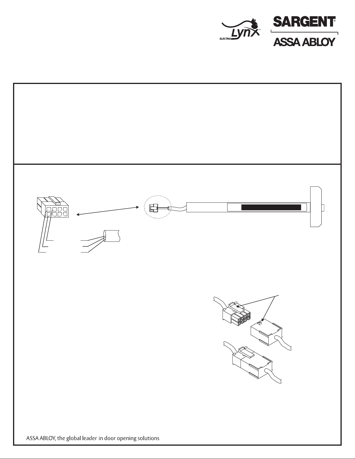
55- or 12-55-
80 Series Rail with 8-pin connector
Brown (NO), 55-
Yellow (NC), 55-
Blue (C), 55-
1
7
5
6
4
3
2
8
Plug
Locking mechanism
Receptacle
Installation and Wiring Instructions for the
55- and 12-55- Prefix (Signal Switch) 80 Series
Exit Device to ElectroLynx™ Connector System
For assistance, contact SARGENT at 800-810-WIRE (9473) or www.sargentlock.com
A. Function
The 55- prefix signal switch monitors the touch bar. When the rail is depressed or dogged, the switch is de-activated.
B. Important
1. Caution: Disconnect all input power before beginning installation to prevent electrical shock and
equipment damage.
2. Installer must be a trained, experienced service person.
3. All wiring must comply with applicable local electrical codes, ordinances and regulations.
C. ElectroLynx Connector System Notes:
Do NOT force connectors on any other way.
The system is designed to be installation friendly with quick
connectors from the electric hinge through the door to the
rail. The only wiring required is to the loose wires on the
pigtail harness assembly on the frame side of the electric
hinge.
IMPORTANT:
The plug and receptacle connectors are designed to mate
and lock together as shown in the figure. Plug the
connectors into each other with the locking mechanism
aligned as indicated.
Copyright©SARGENT Manufacturing. All rights reserved.
Reproduction in whole or in part without the express written
permission of SARGENT Manufacturing is prohibited.
A6808C
Page 2
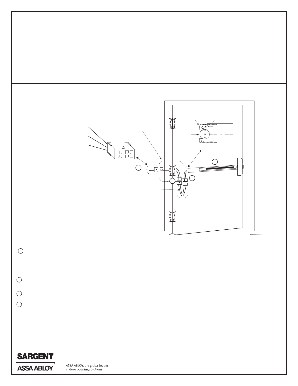
D. Installation Notes
Pigtail harness
with 8-pin connector
Raceway harness with
8 & 4 pin connectors.
The 4-pin connectors
are not used.
Electric Hinge
with 8-pin connectors
Note: Typical raceway location is
shown. Other locations may exist
depending on door type.
4
55- or 12-5580 Series Rail with
8-pin connector
1
75
6
4
3
2
8
Brown (NO), 7
Yellow (NC), 8
Blue (C), 6
55-
Switch
Connections
1
3
2
mounting
bracket
1" dia
hole
in door
screw
location
1. With new applications, a raceway harness with 8 and 4 pin connectors will be pre-installed inside door by
ASSA ABLOY door manufacturer when specified during the ordering process. Raceway harness kits are also
available for retrofit applications.
2. If door does not have a raceway harness with connectors, cut connectors off product, or consult factory for
raceway retrofit kit.
3. Wiring to pigtail harness is per facility wiring requirement. The rail, raceway, electric hinge and pigtail connector
terminations and wire colors all match.
E. 55- 80 Series (Signal Switch) Installation and Wiring
NOTES:
1. Switch contact rating: 2A @ 30VDC
2. Wires must be protected from abrasion
3. For use with class II circuits only
4. Wiring diagram indicates push bar extended
5. The rail, raceway, electric hinge and pigtail
connector terminations and wire colors all match
Mount exit device per instruction sheet provided
1
To insure trouble free operation, check that the push rail can be fully depressed. On vertical rod exit
devices, check that the latch bolts do not go into hold back position until the push rail is fully depressed.
Plug rail connector into raceway connector. Then feed through 1" hole in door. Install rail mounting bracket with two screws
2
supplied. Install rail insert and end cap.
Plug raceway connector into electric hinge connector, then feed through door prep. Mount electric hinge to door.
3
Go to (A) if wiring now. Go to (B) if wiring is to be done later.
4
A. Wire frame side wires to wires on pigtail harness as required using connectors allowed by local
code. Plug pigtail harness connector into electric hinge connector. Feed harnesses through frame prep
and mount electric hinge.
B. Plug pigtail harness connector into electric hinge connector. Feed harnesses through frame prep and mount
electric hinge.
Copyright©SARGENT Manufacturing. All rights reserved.
Reproduction in whole or in part without the express written
permission of SARGENT Manufacturing is prohibited.
A6808C
 Loading...