

Page 1
Installation Instructions
4291 and 4292 Keypads
A6851J
02/11
Copyright 2011, Sargent Manufacturing Company, an ASSA ABLOY Group company.
All rights reserved. Reproduction in whole or in part without the express written
permission of Sargent Manufacturing Company is prohibited.
Page 2
4291 and 4292 Keypads
1
General Description
The 4290 Series Microprocessor Controlled
Keypads provide keyless access primarily for
electric locking devices requiring dry contact
switching. User codes are programmed from
the keypad to perform various functions.
A yellow LED indicates keypad status and red
and green user LEDs can be wired to display
latchbolt and/or door status. The 4291 Keypad
is designed for indoor use in a protective
environment. The 4292 Keypad is weather
resistant and can be used for outdoor use.
2
Specifications
Wallplate Finish
Wall Plate Dimensions
Mounting Screws
Master Codes
User Codes
Memory Backup
Voltage Input
Current Draw 45mA
Green User LED
Red User LED
Yellow User LED
Control Ouput
Momentary Control
Maintained Control
Temperature Range
Tamper Feature
Special Features (Connector Output)
Auxiliary Output (2) 24VDC, 50mA (SINK)
Keypad Active 24VDC, 50mA (SINK)
Panic Output 24VDC, 50mA (SINK)
Request to Exit Dry Contact Activated
Stainless Steel (US32D)
4.50” x 2.75” x 1.53”
(2) 6-32 Tamper Resistant
(2) 6-32 Slotted Oval
1 (1 to 6 digits)
15 (1 to 6 digits)
Non Volatile
24VDC
45mA
24VDC, 15mA
24VDC, 15mA
Keypad Status
SPDT Dry, 8A, @ 24VDC Res.
0 - 90 Seconds
Infinite
-20° - 130°F
3 Incorrect Entries/
15 Second Lockout
3
Functions
1. Control Output (Terminal Strip TS-1)
Enter programmed user code to activate this
output for 0-90 seconds or maintained. This is
a Form “C” dry contact output and should not
exceed 8 AMP (24VAC RES) load. It is used to
control an electric locking device.
2. Auxiliary 1 Output (Wht/Red)
Enter programmed user code to activate this
output for 0-90 seconds. This output should
not exceed a 50mA (24VDC) load. It is used to
control a relay, horn, LED etc.
3. Auxiliary 2 Output (Wht/Blu)
Enter programmed user code to activate
this output for 0-90 seconds or maintained.
This output should not exceed a 50mA
(24VDC) load. It is used to control a relay,
horn, LED, etc.
4. Keypad Active (Wht/Blk)
Enter any key and this output will activate for
10 seconds (from last keypress). This output
should not exceed a 50mA (24VDC) load.
When used in conjunction with an auxiliary
relay, it can control LEDs or a CCTV camera.
5. Panic Output (Org)
Enter * and # keys simultaneously to activate
this output for 1 second duration. The orange
wire output should not exceed a 50mA (24VDC)
load. It is used to control a relay, horn, LED, etc.
6. Request to Exit (Wht/Org, Brn)
A momentary closure (N. O. dry contact) will activate the Control Relay for the same time period
as programmed for the Master Code. It is used
in conjunction with a Motion Detector for exiting.
Refer to Fig. A, following page.
7. Tamper Feature
A 15 second keypad lockout will occur if (3)
improper codes are entered.
8. Passage Mode
Programming this feature changes the state
of the keypad relay contacts. Its intended use
is to maintain the door in the unlocked mode.
Master code and user codes cannot be used
in this mode.
Copyright © 2011, Sargent Manufacturing Company, an ASSA ABLOY Group company. All rights reserved.
Reproductions in whole or in part without express written permission of Sargent Manufacturing Company is prohibited.
02/10/11
2 1-800-810-WIRE • www.sargentlock.com • A6851J
Page 3
4291 and 4292 Keypads
4
Mounting Instructions
A. Important
CAUTION: Disconnect all power before beginning
installation to prevent electrical shock and
equipment damage.
1. Installer must be a trained, experienced
service person.
2. All wiring must comply with applicable local
electrical codes, ordinances and regulations.
B. Installation
1. Mount outlet box to stud or other rigid structure.
Use Outlet Box Slater S1-18W for indoor
applications and Waxman 35-276 for outdoor
applications (not furnished).
2. Install and wire electric locking devices, monitoring components and power sources to appropriate keypad connections.
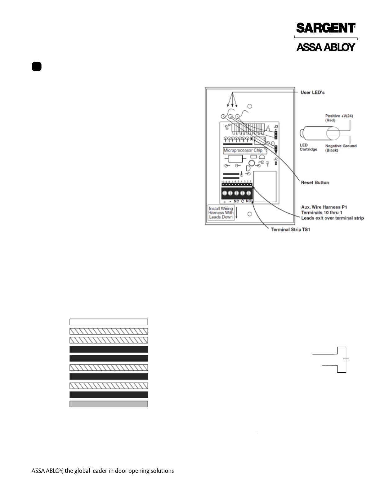
3. Figure A shows color code wiring connections
on keypad.
4. Figure B (pg.3) shows typical wiring when
using SARGENT’s electrical locking devices
with accessories.
5. Fasten wallplate with keypad to outlet box using
machine screw furnished. See Figure C for 4292
keypad outdoor installations.
6. Energize power supply and refer to Programming
Procedures (pg. 5)
Wiring Harness
Warning: Plug this harness in on the proper pins.
Permanent damage will result if incorrectly inserted.
10
9
8
7
6
5
4
3
2
1
Note:
LED’s shown are for the 4291 keypad.
LED’s for 4292 are located on the front right side.
White
Wht/blue
Wht/red
Orange
Brown
Wht/orange
Wht/black
Wht/yellow
Black
Red
Not used
Aux 2 Output (SINK 50mA)
Aux 1 Output (SINK 50mA)
Panic Output (SINK 50mA)
Request to Exit Input
Request Input Common
Keypad Active (SINK 50mA)
N/A
Output Ground (Only)
24 +
Fig. A
1-800-810-WIRE • www.sargentlock.com • A6851J 3
Copyright © 2011, Sargent Manufacturing Company, an ASSA ABLOY Group company. All rights reserved.
Reproductions in whole or in part without express written permission of Sargent Manufacturing Company is prohibited.
02/10/11
Page 4

Typical Wiring with SARGENT Electric Locking Devices,
3510 Power Supply and Door Status Switch
3510
24VDC/1.8AMP
Power Supply
4291 and 4292 Keypads
120VAC
L/N/G
Red (Red LED)
Red (Green LED)
NG ND
L
,1.5A
SLO BLO
INPUT
TFUSE
120VAC, .8A, 60HZ
OUTPUT 1
24VDC, 1.8A
+- +-
OUTPUT 2
(-)(+)
(N.O)
(N.C)
(C)
3287 Door
Status Switch
-
(N.O)
*Red
(N.C)
4291 or 4292
See Note 4
Keypad
Electric Hinge
Fig. B
Copyright © 2011, Sargent Manufacturing Company, an ASSA ABLOY Group company. All rights reserved.
Reproductions in whole or in part without express written permission of Sargent Manufacturing Company is prohibited.
* Colors of wires shown are leads from the
Electric Locking Device only, not Electric Hinge.
02/10/11
4 1-800-810-WIRE • www.sargentlock.com • A6851J
Note:
*Black
Electromechanical Locks
8200/7800 Mortise
10 Lined Bored
773-773 ET
775-776 ET
56- EXIT
58- EXIT
Consult 3287 instruction sheet for proper wire colors
Page 5

4291 and 4292 Keypads
4292 Weather Resistant Mounting Diagram
CAUTION:
The 4292 is not weatherproof, it is only weather
resistant. It may be installed outside, but the
following precautions must be followed.
1. Do not install in any area where direct rain
will strike the keypad or where water will run
down the wall and seep into the keypad.
2. When mounting the 4292 outside, apply
silicone to the area where wires enter the
case, and install a weep hole at the bottom
of the box. This will help prevent warm air
from condensing on the circuit board.
Water shield: This shield should fold down from the top
to allow moisture to run away from the board.
Wires should be run so that they do not
interfere with the placement of the shield.
Tamper resistant
screws recommended
(provided)
4292 Weather Resistant Wiring Diagram Notes
1. Wires must be protected from abrasion.
2. For use with Class II circuitry only.
NOTE: Dots ( • ) indicate wire connections.
3. Use N.C. Relay Contacts for Fail Safe Lock (normally energized). Use N.O. Relay Contacts for
Fail Secure Lock (normally de-energized).
4. Insulate any loose wires from Outlet Box and
each other.
5. When operating inductive loads such as electric
strikes and solenoid operated locks (10G70-73,
8270-73 etc.) the supplied transorb must be
installed.
For locking devices that have built in protection,
the use of the transorb is not necessary. Refer
to the literature furnished with the locking device
for this information. SARGENT 56-, 57-, 58- and
59- devices do NOT require use of transorb.
IMPORTANT:
The transorb must be installed as close to the
locking device as possible. This is to prevent the
electrical (inductive) kickback voltage generated
by the locking device from damaging the keypad.
Wiring Harness
24VDC
24VDC
Gasket (provided)
4291 or 4292
Keypad
+ - NC C NO
4291 or 4292
Keypad
+ - NC C NO
Magnetic Door
Lock (Fail Safe)
Transorb
Electric Strike
(Fail Secure)
Transorb
Add weep hole for
wet environment
Copyright © 2011, Sargent Manufacturing Company, an ASSA ABLOY Group company. All rights reserved.
Reproductions in whole or in part without express written permission of Sargent Manufacturing Company is prohibited.
1-800-810-WIRE • www.sargentlock.com • A6851J 5
02/10/11
Page 6

4291 and 4292 Keypads
Programming
5
The keypads come pre-programmed with the master code 1234*.
The master code is used to program your fifteen (02-16) user codes and functions.
If you are unsure of where you are in programming, press the * key several times until the yellow LED is off and
start again at the beginning. Also, if no key is pressed for 30 seconds, the programming mode in process is
automatically aborted.
A. Program Users Codes 2 Through 16
1. Enter 99# to initiate programming sequence.
2. Enter Master Code*.
This code can be changed, refer to
3. Enter two digit time duration desired.
Enter 01 to 90 seconds for Momentary Function. Enter 00 for Maintained Function.
4. Enter two digit user number.
Enter 02# to 16#.
5. Enter Selected User Code.
Use between a one and six digit number followed by a *.
6. Repeat step 5.
C. Changing the Master Code.
Sample Programming:
B. Delete User Codes 2 through 6
1. Enter 99# to initiate deleting sequence.
2. Enter Master Code*.
This code can be changed, refer to C. Changing the Master Code.
3. Enter two digit user number desired to be deleted.
Enter 02# to 16#.
4. Enter ** to complete deletion.
Copyright © 2011, Sargent Manufacturing Company, an ASSA ABLOY Group company. All rights reserved.
Reproductions in whole or in part without express written permission of Sargent Manufacturing Company is prohibited.
02/10/11
6 1-800-810-WIRE • www.sargentlock.com • A6851J
Page 7

4291 and 4292 Keypads
C. Changing the Master Code
1. Enter 99# to initiate programming sequence.
2. Enter current Master Code*.
3. Enter time duration: 01-90 seconds.
4. Enter 01#.
5. Enter new desired Master Code.
6. Use between a one and six digit number,
followed by a *.
7. Repeat step 5.
Sample Programming:
D. Programming for Special Functions
1. Enter 99# to initiate programming sequence.
2. Enter Master Code*.
3. Enter Special Function Code.
91-Code operates Aux 1./Time Duration
92-Code operates Aux 2./Time Duration
98-Code operates Aux 1, and
Control Relay (Master Code duration)
4. Enter two digit time duration desired.
Enter 01 to 90 seconds for momentary Function.
Enter 00 for Maintained Passage Function.
5. Enter User Number. Enter 01# to 16#.
6. Enter Selected User Code. Use between a one
and six digit number followed by a *.
7. Repeat Step 6.
Sample Programming:
NOTES:
• If LED does not turn off, the code entered
has not been verified.
Press * and repeat Steps 1-6.
• If the Master Code is unknown, Programming or
Changing Mode can be entered by removing the
keypad from the outlet box and momentarily
pressing SW1 (reset button) on the circuit board.
For location, see Mounting Instructions, page 2.
• The yellow LED will flash slowly and programming
should proceed from Step 3.
NOTES:
1. If User Number 01# is used then its user code
is the master code.
2. Special function 98 should not be used
with User 01#.
3. AUX1 duration is common for all users of
AUX1. Changing it for one user changes
it for all users.
4. Special Function 98 uses duration set in
section "c" for Main Relay and common
duration for AUX1. Setting a duration for
Special Function 98 is ignored.
1-800-810-WIRE • www.sargentlock.com • A6851J 7
Copyright © 2011, Sargent Manufacturing Company, an ASSA ABLOY Group company. All rights reserved.
Reproductions in whole or in part without express written permission of Sargent Manufacturing Company is prohibited.
02/10/11
Page 8

SARGENT Manufacturing
100 Sargent Drive
New Haven, CT 06511 USA
800-810-WIRE (9473) • www.sargentlock.com
Founded in the early 1800s, SARGENT® is a market leader in locksets, cylinders, door closers, exit devices,
electro-mechanical products and access control systems for new construction, renovation, and replacement applications.
The company’s customer base includes commercial construction, institutional, and industrial markets.
Copyright © 2011, Sargent Manufacturing Company, an ASSA ABLOY Group company. All rights reserved.
Reproduction in whole or in part without the express written permission of Sargent Manufacturing Company is prohibited.
ASSA ABLOY is the global leader in door opening solutions, dedicated to
satisfying end-user needs for security, safety and convenience.
A6851J -02/11
 Loading...