

Page 1
421 CAM ACTION DOOR CLOSER
H
INGE SIDEHINGE SIDE
S
TOP SIDE STOP SIDE
R
IGHT
HAND DOOR
L
EFT
HAND DOOR
(PCTB & PCHTB) PUSH SIDE TRACK
APPLICATION INSTALLATION INSTRUCTIONS
CAUTION: FAILURE TO INSTALL OR ADJUST PROPERLY MAY RESULT IN INJURY OR DAMAGE
For assistance, contact SARGENT at 800-727-5477 or www.sargentlock.com
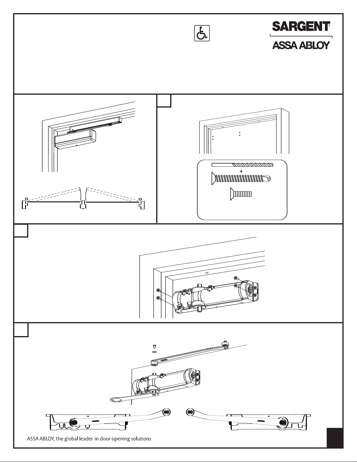
NOTE: AN AUXILIARY DOOR STOP IS REQUIRED
MEASURE & MARK HOLES. PREP HOLES USING DIMENSIONS
A
ON PAGE 4
EFT HAND
L
SHOWN
OR
for self tapping screws or #16 drill and tap
WITH PROVIDED FASTENERS, SECURE CLOSER BODY TO DOOR WITH POWER ADJUSTMENT FACING
B
AWAY FROM HINGE SIDE OF DOOR.
When using mortise nuts,
see accessories on page 3
WITH A WRENCH, ROTATE THE BOTTOM SPINDLE TOWARD HINGE APPROXIMATELY 15°. SECURE ARM TO SPINDLE
C
WITH SCREW AND WASHER PROVIDED
Warning: If not properly indexed, door
closer will not operate properly
Left Hand Shown
(Right Hand Opposite)
Pre-drill - 3/32” holes
#12-24 UNC for machine screws
Left Hand
© Sargent Manufacturing Company 2007
Right Hand
A7959A
1
Page 2
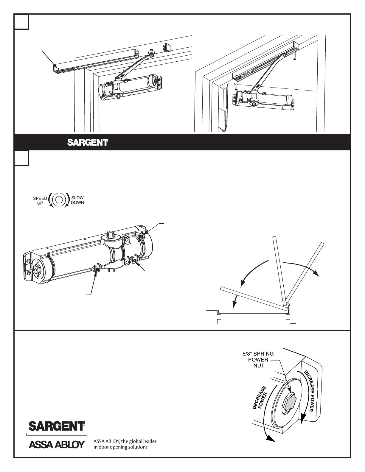
SLIDE TRACK OVER ROLLER AND INSTALL END CAPS. SECURE TRACK TO FRAME WITH SCREWS PROVIDED.
CLOSING SPEED
LATCHING SPEED
BACKCHECK
D
NOTE: ORIENT TRACK SO STOP PIN IS
ON HINGE SIDE OF DOOR
FINAL ADJUSTMENT AND REGULATING PROCEDURE
– Adjust door speed and latching speed valves to achieve the desired closing time. 6 seconds minimum from 90° to the
E
closed position is recommended.
– If backcheck is required, adjust valve to achieve a slight cushioning effect. Auxiliary stop required.
Use 5/32" hex wrench to
adjust valves
CLOSING SPEED
RANGE
LATCHING SPEED
RANGE
ADJUST POWER TO MINIMUM REQUIRED TO RELIABLY CLOSE AND LATCH DOOR
– If door is hard to open, decrease power slightly
– If door does not latch, increase power as required
– Doors adjusted with high closing power to overcome strong
draft conditions may exceed ADA standards.
BACKCHECK
RANGE
421 CLOSERS
FIELD ADJUSTABLE
FOR SIZES 1-6
ARE
© Sargent Manufacturing Company 2007 A7959A
Page 3

HOLD OPEN
MECHANISM
BUMPER
STOP PIN
TENSIONER
F
GAP
Move insert
as needed
Small screw
Long screw
FRAME
UNREINFORCED
DOOR
DOOR STOP
MORTISE NUT
DRILL 3/8" DIA.
HOLE FOR MORTISE
NUT BODY
DRILL 1/4" DIA. HOLE
FOR MOUNTING SCREWS
INSTALL COVER AS FOLLOWS:
1. SCREW SHORT COVER SCREW (#8-35 x 5/16)
INTO TOP OF CASE APPROXIMATELY 2 TURNS
2. ASSEMBLE PLASTIC SUPPORT AND LONG
COVER SCREW (# 8-32 x 1-1/4 ) INTO BOTTOM
OF CASE APPROXIMATELY 2 TURNS.
3. HOLD SUPPORT AGAINST CASE AND SLIDE
OVER INTO GAP BETWEEN FLANGE AND
C
SCREW HEAD
4. POSITION COVER ON CLOSER AND
TIGHTEN SCREWS
FOR MODELS HAVING “PCHT” HOLDER
ARMS
The holder device is set for 85° door holding position at the factory.
Tension is set at the highest setting.
- To decrease holding tension: Remove tensioner mounting screw and move tension adjuster away
from hold open mechanism by using either of the two hole locations.
- To change hold open position: Remove hold open mechanism and tensioner mounting screws;
slide both to desired position and reinstall screws.
- To decrease the degree of door opening: Move stop pin to desired position
ACCESSORIES INFORMATION
MORTISE NUT INSTRUCTIONS
© Sargent Manufacturing Company 2007 A7959A
Page 4

3/4"
RELEASE DATE
TEMPLATE NO
.
100 Sargent Drive New Haven, CT 06511
Manufacturing Company
8 May , 2007
C
L
OF
HINGE
DATA SHEET
421 SERIES CLOSER WITH PCTB OR PCHTB
ARMS - PUSH SIDE APPLICATION
NOTE:
LEFT HAND DOOR SHOWN, RIGHT HAND OPPOSITE1.REINFORCE METAL DOORS AND FRAMES PER ANSI A250.8 AND
2.
SDI-100 , 12 GAUGE RECOMMENDED
USE 1431-J PLATE WHEN CLOSER BODY IS VISIBLE THROUGH GLASS
3.
THE MINIMUM TOP RAIL MAY BE REDUCED BY 3/4" BY USING THE
4.
1431-D MOUNTING PLATE. SEE TEMPLATE A7168
MAXIMUM OPENING POSITION 125°
5.
ADJUSTABLE HOLD OPEN RANGE: 75° -120° (HOLDER MODEL ONLY)6.AUXILIARY STOP REQUIRED
7.
FRAME
REINFORCEMENT
DOOR
REINFORCEMENT
2
2
#12-24 X 5/8 FLAT HEAD MACHINE
SCREW OR #12 X 1 1/2 SCREW
PROVIDED
#12-24 X 1 3/4 FLAT HEAD MACHINE
SCREW OR #12 x 1 3/4" SCREW PROVIDED
TOP OF
DOOR
3
TRACK
421 CLOSER
OUTLINE OF
COVER
FACE OF
STOP
4
C
L
OF TRACK
A 7961 A
1 3/8"
6"
21 5/8"
1"
11 1/8"
1/2"1/2"
3 1/4"
TOP RAIL
2 3/8"
15 1/8"
4 5/8" MIN
5 1/2"
1/2"
© Sargent Manufacturing Company 2007 A7959A
 Loading...