

Page 1
R
80-9369-0901-021 (12-02 )
120VOLT POTENTIAL PRESENT. MAKE SURE POWER INPUTTO UNIT IS
TURNED OFF DURING INSTALLATION AND WIRING PROCEDURE.
REQUIREMENTS:
•
U.L. labeled fire or smoke barrier door assemblies require
that the 120VAC, 60Hz power input to the Power Door
Operator be supplied through normally closed alarm
contactsofthealarmsystem/alarmpanel.
•
All wiring and connections use standard wiring practice
conformingwithlocalwiringcodes.
•
Power inputs at terminal strip T1 and at terminal strip JP4 must
bemadewithcopperwireonly.
•
Maximumwiresizeis:
12AWGatPowerInputTerminalStrips
14AWGatTerminal StripsJP1 And JP4
Note:
No power/voltage inputs are to be made to the Door
Operator unit except 120VAC, 60Hz (+10% -15%) at terminals
HOTandCOMofthe PowerInputTerminal StripT1.
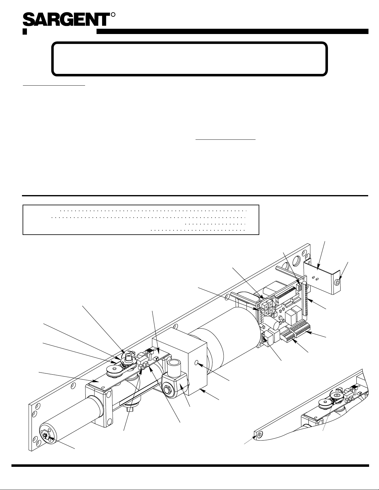
Low Energy Door Operators
Wiring Instructions For 4051, 4052, 4060, 4067
•
Typicalfield connections forflexibleconduit illustratedonpage2.
•
Power input terminal strip T1 at terminals Hot and COM must be
120VAC at 60Hz (+10% -15%).
•
Current draw at auxiliary contact JP4 – 2 must not exceed 0.500
amps, for auxiliary devices.
GENERAL DATA:
••Maximum current draw of Door Operator units without peripheral
sensors orscanners is1.5 ampswhen motor is operating, .050 amps
instandby.
Maximum current draw from auxiliary devices is 0.500 amps
(terminals JP4 – 1 and JP4 – 2).
Fuse “F2”protects the Electronic Control Module and Transformer
circuit and is a 3 amp slow blow fuse.
Requirements
Unit Wiring
Control Module Layout and (Input/Output Connections;Functions)
Typical Application – Point to Point Wiring Diagrams
Field Reversible
Unit Shown
Square Spindle End
Protrudes
Spindle Timing
Pulley for Field
Reversible
Units
Timing Belt
ELS Board w/
ELS Board
Pulley
ELS Board
LED
JP2
Terminal
Strip
S
P
Rotary Switches/
C
H
US
Timer Pots
(SC) Speed
Control Valve
1
2
3-5
6-15
SW1
Dip
Switches
Main Board
JP3
Terminal
Strip
Bracket for
Input Power
Terminal Strip
T1
Fuse
F2
JP1
Terminal
Strip
JP4
Terminal
Strip
JP5
Terminal
Strip
80-9369-0901-021 (12-02 )
11/16" Power
Adjustment Nut
Door Calibrate
Open Position
Solenoid
Door Calibrate
Close Position
1
Application
(REF)
Handed Unit
Shown
Spindle Timing
Pulley
Handed Units
A7666A
Page 2
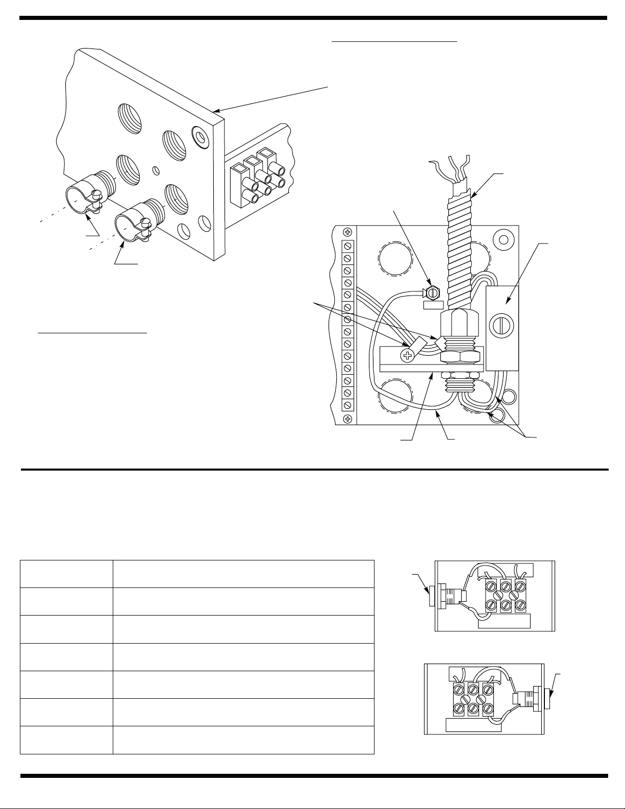
CONCEALEDWIRING
Threadconduitfitting(s) intobackplateasshown.
Asecond conduitfittingis requiredforlow voltage
control wiring. CHECK LOCAL CODES. Pull
conduit out of header and attach to conduit
fittings before mounting Operator to door frame.
Attach incoming ground wire to backplate with
groundscrewasillustratedbelow.
Conduit by Others
(from top)
(Green) Ground Screw
Low Voltage
Control
Wiring
Incoming
Power
SURFACE WIRING
An optional bracket is provided for use with
surfacewiring. Remove thetwo cable clamps
screws and slip the bracket under the cable
clamps. Push the cable clamp screw through
the bracket holes and tighten. ½” conduit
fittingscannowbeinstalledonthebracket.
INSTALLER / USER INFORMATION
Input PowerTerminal Strip
Terminals 22 through 25 are factory wired using 18AWG wire.
– 120VAC, (+10% - 15%) InputVoltage. Maximum wire size 12 AWG at terminals HOT and COM.
Cable
Clamps
Optional Bracket
(for surface wiring)
Ground
Lead
“T1” Power
Input
Terminal Strip
Bracket
Power
Leads
Earth GroundWire Connection
InputTerminal Strip bracket. Screw labeled“GND”.
– Groundwire must be secured to backplate under head of (green) groundscrew nearestto “T1” Power
Terminal Description
COM
(Neutral)
HOT
(Line)
25
24
23
22
2
Commonpowerlead
Hotpowerlead
Fuseconnection
Hot connection to PC board JP5 – 2 and to hot
primarysideof120V/24Vtransformer.
Fuseconnection
Common connection to PC board JP5 – 1 and to
commonprimarysideof 120V /24Vtransformer.
Fuse F2*
22
23
24
25
HOT
COM
Left Hand Double Lever, Push Side
Right Hand Slide Track, Pull Side
23
22
24
COM
HOT
25
Right Hand Double Lever, Push Side
Left Hand Slide Track, Pull Side
80-9369-0901-021 (12-02 )
Fuse F2*
Page 3
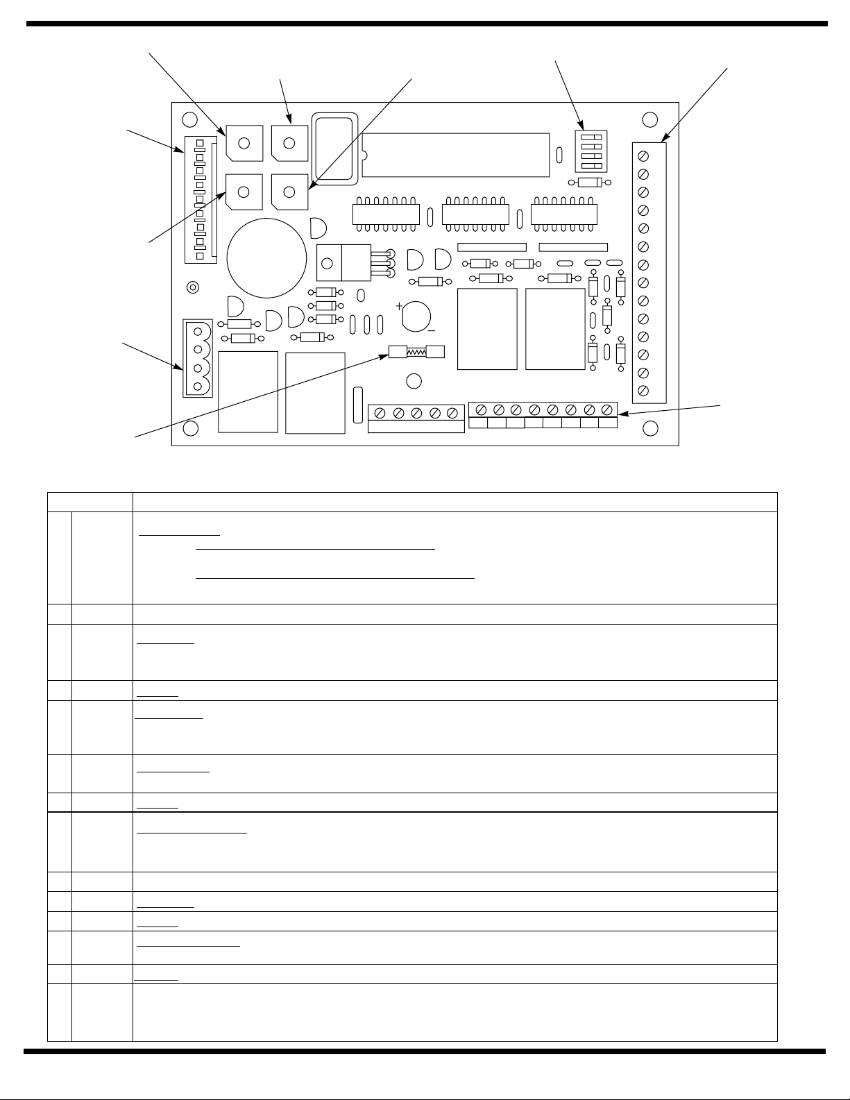
SW5 Rotary
Switch/Timer
Pot
SW4 Rotary
Switch/Timer
Pot
SW2 Rotary
Switch/Timer
Pot
SW1 Dip
Switches
JP1 Terminal
Strip
JP2 Terminal
Strip
SW3 Rotary
Switch/Timer
Pot
JP3 Terminal
Strip
Fuse F1
1.5 amp,
2AG
JP2
G
EM
G
H+VL2
G
L1
JP3
MOTOR/SOLENOID
CL/AS DLY
3
4
2
1
5
0
6
9
7
8
EXSOL DLY
3
4
2
1
5
0
6
9
7
8
Relay
K2
VEST DLY
3
4
2
1
0
9
7
8
M. DLY
3
4
2
1
0
9
7
8
5
6
5
6
Relay
K1
NEU HOT GND 18VAC
DOOR OPERATOR
41-6700-0056 REV A MADE IN USA
Relay
K3
JP5
1 2 3 4 5 6 7 8
GND+24V NO1 CO1
OFF
Relay
K4
NC1
SW1
NO2 CO2 NC2
ON
P/A
A/D
RES1
RES2
JP4
JP1
14
AUX1
13
GND
12
PDET
11
GND
10
AUX2
9
GND
T
F
8
R
7
GND
6
OUTV
5
INV
4
GND
3
AUX2
2
RES1
1
0/0
JP4 Terminal
Strip
Slo-Blo
Electronic Control Module (Main PC Board)
JP1Terminal Strip – Maximum wire size 14AWG. For signaling only, do not make power input connections.
TERMINAL D E S CRIPTION
Override Open
1 0/0
– This terminal has two possible functions that can be used together or separately.
1. – Upon initiation of a closed signal from a fire/ smoke alarm
SmokeVentilation Door or Blow Open Door
panel, door will open and remain open until signal is terminated. Use with any JP1 ground.
2. – Time is set with dip switch SW1 – 2 A/D. (OFF = 30
Alarm Delay (30 second or 60 second time period)
second delay, ON = 60 second delay) Use with any JP1 ground.
2 RES1 This is not an active contact.
– This is one of two secondary initiating switch contacts (JP1 – 10 is the other.)
3 AUX2
Auxiliary 2
For most applications it is equivalent to AUX1 JP1 – 14. For Vestibule Function use, it is the contact for a switch
located within the vestibule. Use with any JP1 ground.
4 GND Ground
In Vestibule – Used for Vestibule Function. This contact must be connected to the JP1 – 6 terminal from another
5 INV
unit to receive an initiating signal. The signal is then programed to initiate the unit by setting theVEST DLY rotary
switch/timer pot of the receiving unit. Use this contact with any JP1 ground.
6 OUTV
Out Vestibule
send an initiating signal. Use with any JP1 ground.
– Used forVestibule Function. This contact must be connecter to terminal JP1 – 5 of another unit to
7 GND Ground
– With the unit’s 3 Position Slide Switch in the “ON” position, a signal will open the door and
8 RFT
Maintain Hold Open
maintain an indefinite hold open until a second signal releases the door from hold open. Use with any JP1 ground.
This feature recommended for Power Operator Function. If using with the Power Assist Function, consult factory.
9 GND Ground
10 AUX2 – Same as JP1 – 3 / AUX2 above.Auxiliary 2
11 GND Ground
12 PDET
Presence Detector
fully open from closing. Use with any JP1 ground.
– Permits wiring of a presence detector to prevent a closed door from opening or a door that is
13 GND Ground
Auxiliary 1 – Primary initiating switch contact. Initiates door power cycle. Must be Normally Open Momentary Dry
14 AUX1
Contact. For Vestibule Function, the switch at outside of vestibule is connected to this terminal. (Outside switch to
outside unit’s JP1 – 14. Inside switch to inside unit’s JP1 – 14). Use with any JP1 ground.
80-9369-0901-021 (12-02 )
3
Page 4
JP4Terminal Strip – Maximum wire size 14AWG.
TERMINAL D E S CRIPTION
1 GND Ground
2 +24
3 NO1
24VDC (unregulated) to a maximum current draw of 0.500 amps. Use with ground terminal JP4 – 1.
DO NOT
A separate 24VDC filtered and regulated supply must be used.
Control (Relay Contact Only – 5Amp @ 24VDC) – Normally open contact that is switched by Relay K3 (on main
board) to close. Relay K3 will remain switched for a period set by SW – 3 EXSOL DLY rotary switch / timer pot.
Use with terminal JP4 – 4 CO1. Coordinate use of this terminal with delayed start of motor using rotary timer pot
SW – 2 M DLY.
use this supply with 56- Latch Retraction Exit Device.
output
4 CO1
5 NC1
6 NO2
7 CO2
8 NC2
Control (Relay Contact Only ) – Common contact for use with terminals JP4 – 3 NO1 and JP4 - 5
Nc1.
Control (Relay Contact Only – 5Amp @ 24VDC) – Normally closed contact that is switched by Relay K3 (on main
board) to open. Relay K3 will remain switched for a period set by SW – 3 EXSOL DLY rotary switch / timer pot.
Use with terminal JP4 – 4 CO1. Coordinate use of this terminal with delayed start of motor using rotary timer pot
SW – 2 M DLY.
Alarm Delay (Switching Contact Only ) – Normally open contact that is switched by relay K4 (on
main board) to close. Relay K4 will remain switched for a period set by Dip Switch SW1 – 2 A/D (OFF = 30 second
delay;ON = 60 second delay). Use with terminal JP4 – 7 Co2.
Alarm Delay – 5Amp @ 24VDC
and JP4 – 8 NC2.
Alarm Delay
main board) to open. Relay K4 will remain switched for a period set by Dip Switch SW1 – 2 A/D (OFF = 30 second
delay;ON = 60 second delay). Use with terminal JP4 – 7 Co2.
(Switching Contact Only ) – Common contact for use with terminals JP4 – 6 NO2
(Switching Contact Only – 5Amp @ 24VDC) – Normally closed contact that is switched by relay K4 (on
– 5Amp @ 24VDC
– 5Amp @ 24VDC
Main Board Switches
DIP SWITCHES (MAIN BOARD) DESCRIPTION
1 P/A
2 A/D
3 RES1 DIAGNOSTIC USE. FOR FACTORY AUTHORIZED PERSONAL.
4 RES2 DIAGNOSTIC USE. FOR FACTORY AUTHORIZED PERSONAL.
Door Operator Function Switch – OFF position selects the Power Operator Function. On
position sets the Power Assist Function.
Alarm System Delay Timer – This switch is used in conjunction with terminal Jp1– 1, 0/0 for
optional function 2. (OFF = 30 second delay, ON = 60 second delay).
ROTARY SWITCHES DESCRIPTION
SW2 M DLY
SW3 EXSOL DLY
SW4 VEST DLY
SW5 CL/AS DLY
Chart 1 – SW2, M DLY
Length of Time
(Seconds)
0.0
0.2
0.5
1.0
1.5
2.5
3.5
4.5
Settings
0
1
2
3
4
5
6
7
This rotary switch or timer pot sets the length of delay for motor start up to allow for“unlocking”
of exit devices, electric strikes, magnetic locks, etc. See Chart 1 for delay times.
This rotary switch or timer pot sets the length of time that a solenoid remains either energized or
de-energized to allow “unlocking”. Used in conjunction with terminals JP4 – 3, JP4 – 4, JP5 – 5.
See Chart 2 for length of time.
This switch or timer pot sets the length of time between receipt of the“In Vestibule”signal
(terminal JP1 – 5) and motor start-up. See Chart 3 for delay times.
Controls either one of two function times:
Power Operator Function
Power Assist Function
force. When time elapses, the door force reverts to full opening spring force set.
Chart 2 – SW3, EXSOL DLY
Length of Time
(Seconds)
0
1
2
4
6
8
10
12
– Sets length of time door holds open at fully “taught”open position.
– Sets length of time motor and pump will operate to reduce opening
Chart 3 – SW4, VEST DLY
Settings
0
1
2
3
4
5
6
7
Length of Time
(Seconds)
0
1
3
6
9
14
21
30
Settings
0
1
2
3
4
5
6
7
Chart 4 – SW5, CL/AS DLY
Length of Time
(Seconds)
0
2
5
10
15
20
25
30
Settings
0
1
2
3
4
5
6
7
4
80-9369-0901-021 (12-02 )
Page 5
JP2Terminal Strip – Factory Wired Connections.
TERMINAL D E S CRIPTION
L1
G – Ground. Common connection for L1 and L2 inputs.Black Wire
L2
+V +24VDC. This terminal is used to supply power to the ELS Board.YellowWire
H – Hold Open contact of“OFF” “ON” “H/O”switch assembly.Violet Wire
G – Ground. Common contact of “OFF”“ON” “H/O”switch assembly.White Wire
M Orange Wire – ON contact of “OFF”“ON” “H/O”switch assembly.
E
G – Ground. Use with terminal Jp2 – E for Emergency Hold Open Release.Black Wire
White Wire
or pulled in the open direction. Movement of potentiometer on ELS Board signals L1 input.
Blue Wire
during the teaching mode.
Red Wire
door immediately at any point of door opening once an obstruction on opening is encountered. It is used with
terminal JP2 – G.
– High side of L1 Input signal from ELS Board. Detects door motion to open door when door is pushed
– High side of L2 Input signal for ELS Board. Detects the Fully Open Position stored in the ELS Board
– Emergency Hold Open Release. This contact is used in conjunction with the ELS board to close the
JP5Terminal Strip – Factory Wired Connections.
TERMINAL D E S CRIPTION
1 NEU Common 120V connection to Input PowerTerminal 22.
2 HOT Hot 120V connection to Input PowerTerminal 24.
3 GND
4 18VAC From secondary of 120V / 24V transformer.
5 18VAC From secondary of 120V / 24V transformer.
Ground connection secured to backplate under head of (green) ground screw that is located under Main PC Board.
Screw Labeled “GND”
JP3Terminal Strip – Factory Wired Connections.
TERMINAL D ESCRIPTION
MOTOR Motor Connection.
SOLENOID Solenoid coil connection.
80-9369-0901-021 (12-02 )
5
Page 6

Standard Function with Switches
Operation:
Doors arenormallyclosed.
Activating either switch will open both doors. Door will
closeafter hold open time delayhaselapsed.
Wall Switch, Card
Reader, Key Switch,
etc.
Normally Open Momentary
dry contacts
JP2
G
EM
G
H+VL2
G
L1
MOTOR/SOLENOID
EXSOL DLY
JP3
Door 1
CL/AS DLY
3
4
2
1
5
0
6
9
7
8
3
4
2
1
5
0
6
9
7
8
NEU HOT GND 18VAC
VEST DLY
3
4
2
1
0
9
7
8
M. DLY
3
4
2
1
0
9
7
8
SW1
5
6
5
6
JP5
1 2 3 4 5 6 7 8
GND+24V NO1 CO1
OFF
NC1
NO2 CO2 NC2
ON
P/A
A/D
RES1
RES2
JP4
JP1
0/0
1
14
AUX1
13
GND
12
PDET
11
GND
10
AUX2
9
GND
T
F
8
R
7
GND
6
OUTV
5
INV
4
GND
3
AUX2
2
RES1
1
0/0
RES1
AUX2
GND
INV
OUTV
GND
RFT
GND
AUX2
GND
PDET
GND
AUX1
2
3
4
5
6
7
8
9
10
11
12
13
14
JP1
Door 2
RELAY CONTACTS FOR
ELECTRIC STRIKE.
ELECTRIC LATCH RETRACT
EXIT DEVICE, MAGNETIC
LOCK, ETC.
See Note 3.
Wall Switch, Card
Reader, Key Switch,
etc.
Normally Open Momentary
dry contacts
Notes:
Note 3:
If product being connected does
not have an integrated diode, one
must be installed across contracts
to protect relays . Suggested diode is
1N4001 or equivalent.
1.Power input Door Operator Unit is at
Power Input Terminal Strip (not shown)
120VAC 60Hz.
2.Current draw must not exceed 0.500
amps at terminal JP4 – 2.
See pages 9 - 11 for illustration of use.
6
80-9369-0901-021 (12-02 )
Page 7

Vestibule Function
Operation:
G
Doorsare normallyclosed.
EM
Activating outside door switch will open the outside
G
H+VL2
CL/AS DLY
JP2
EXSOL DLY
door. After the vestibule time delay has elapsed, a
signalwill be sent to the inside doorwhichwill open.
VEST DLY
3
2
1
0
9
8
3
2
1
0
9
8
3
4
7
4
7
4
2
1
5
6
5
6
0
9
8
M. DLY
3
2
1
0
9
8
5
6
7
4
5
6
7
6600/6700 SERIES DOOR OPERATOR
41-6700-0056 REV A MADE IN USA
Activating the inside door switch will open the inside
door. After the vestibule time delay has elapsed, a
G
signal will be sent to the outside door which will
L1
open.
Both doorswill closewhen thehold open time delay
haselapsed.
JP3
MOTOR/SOLENOID
Activating the inside Corridor door switch located
with-in the corridor will open the inside door only.
This doorwill re-closeafter thehold open delay has
elapsed.
Activating the outside Corridor door switch located
with-in the corridor will open the outside door only.
NEU HOT GND 18VAC
This doorwill re-closeafter thehold open delay has
elapsed.
RELAY CONTACTS FOR
ELECTRIC STRIKE.
ELECTRIC LATCH RETRACT
EXIT DEVICE, MAGNETIC
LOCK, ETC.
See Note 3.
JP5
1 2 3 4 5 6 7 8
GND+24V NO1 CO1
VESTIBULE
SW1
OFF
NC1
NO2 CO2 NC2
ON
P/A
A/D
RES1
RES2
JP4
Inside
Corridor Switch
Outside
Corridor Switch
JP1
Inside Switch
All Switches are either
14
AUX1
13
GND
12
PDET
11
GND
10
AUX2
9
8
7
6
5
4
3
2
1
INSIDE DOOR
GND
T
F
R
GND
OUTV
INV
GND
AUX2
RES1
0/0
Wall Switches, Card
Readers, Key Switches,
etc.
Normally Open Momentary
dry contacts
JP2
G
EM
G
H+VL2
G
L1
MOTOR/SOLENOID
EXSOL DLY
JP3
CL/AS DLY
VEST DLY
3
2
1
0
9
8
3
2
1
0
9
8
3
4
7
4
7
4
2
1
5
6
5
6
0
9
8
M. DLY
3
2
1
0
9
8
5
6
7
4
5
6
7
Note 3:
If product being connected does
not have an integrated diode, one
must be installed across contracts
to protect relays . Suggested diode is
1N4001 or equivalent.
See pages 9 - 11 for illustration of use.
DOOR OPERATOR
41-6700-0056 REV A MADE IN USA
JP5
NEU HOT GND 18VAC
1 2 3 4 5 6 7 8
GND+24V NO1 CO1
RELAY CONTACTS FOR
ELECTRIC STRIKE.
ELECTRIC LATCH RETRACT
EXIT DEVICE, MAGNETIC
LOCK, ETC.
See Note 3.
OFF
NC1
NO2 CO2 NC2
SW1
ON
P/A
A/D
RES1
RES2
JP4
JP1
Outside Switch
14
AUX1
13
GND
12
PDET
11
GND
10
AUX2
9
GND
T
F
8
R
OUTSIDE DOOR
7
GND
6
OUTV
5
INV
4
GND
3
AUX2
2
RES1
1
0/0
Notes:
1.Power input Door Operator Unit is at
2.Current draw must not exceed 0.500
Power Input Terminal Strip (not shown)
120VAC 60Hz.
amps at terminal Jp4 – 2.
80-9369-0901-021 (12-02 )
7
Page 8

Notes:
1.Power input Door Operator Unit is at
Power Input Terminal Strip (not shown)
120VAC 60Hz.
2.Current draw must not exceed 0.500
amps at terminal JP4 – 2.
Radio Frequency Function Options
Operation:
Option1.
Door is normally closed.
Activating wireless switch or hand held
wireless transmitter will open the door.
NEU HOT GND 18VAC
JP5
GND+24V NO1 CO1
1 2 3 4 5 6 7 8
Door will close after hold open delay
elapses.
Option 2.
Door is normally closed.
Activating a wireless switch or hand held
wireless transmitter will open the door.
Door will remain in indefinite hold open
until wireless switch or hand held
transmitter is activated a second time
causing the door to close.
RELAY CONTACTS FOR
ELECTRIC STRIKE.
ELECTRIC LATCH RETRACT
EXIT DEVICE, MAGNETIC
LOCK, ETC.
See Note 3.
GREEN (NO)
BLACK
WHITE (C)
RED
NC1
NO2 CO2 NC2
JP4
RF
RECEIVER
3
2
1
RES1
0/0
AUX2
GND
OPTION 1
WIRING FOR
STANDARD
MOMENTARY
HOLD OPEN
FUNCTION
OFF
SW1
RES2
RES1
ON
A/D
P/A
JP1
14
13
12
11
10
9
8
7
6
5
4
INV
OUTV
GND
GND
GND
AUX2
T
F
R
PDET
GND
AUX1
1 2 3 4 5 6 7 8 9 10 11 12 13 14
OPTIONAL SECOND
LOW ENERGY
POWER OPERATOR
OPTION 2
GREEN (NO)
BLACK
RF
RECEIVER
WHITE (C)
RED
8
WIRING FOR
TOGGLE / MAIN-
TAINED
HOLD OPEN
FUNCTION
Note 3:
If product being connected does
not have an integrated diode, one
must be installed across contracts
to protect relays . Suggested diode is
1N4001 or equivalent.
See pages 9 - 11 for illustration of use.
80-9369-0901-021 (12-02 )
Page 9

Fail Secure Electric Strike 24VDCWiring
JP2
G
EM
G
H+VL2
G
L1
MOTOR/SOLENOID
EXSOL DLY
JP3
CL/AS DLY
3
4
2
1
5
0
6
9
7
8
3
4
2
1
5
0
6
9
7
8
NEU HOT GND 18VAC
VEST DLY
3
4
2
1
0
9
7
8
M. DLY
3
4
2
1
0
9
7
8
SW1
5
6
5
6
JP5
1 2 3 4 5 6 7 8
GND+24V NO1 CO1
OFF
NC1
NO2 CO2 NC2
ON
P/A
A/D
RES1
RES2
JP4
JP1
14
AUX1
13
GND
12
PDET
11
GND
10
AUX2
9
GND
T
F
8
R
7
GND
6
OUTV
5
INV
4
GND
3
AUX2
2
RES1
1
0/0
Wall Switch, Card
Reader, Key Switch,
etc.
Normally Open Momentary
dry contacts
Diode 1N4001
Operation:
Dooris normallyclosed and latched.
Activating switch will unlock the electric strike and the
door will automatically open. Door will close after hold
opentime delayhaselapsed.
Thedoor will remain duringpowerfailure.locked
+
-
24VDC Electric Strike
(fail Secure)
Notes:
1.Power input Door Operator Unit is at
Power Input Terminal Strip (not shown)
120VAC 60Hz.
2.Current draw must not exceed 0.500
amps at terminal JP4 – 2.
80-9369-0901-021 (12-02 )
9
Page 10

Fail Safe Electric Strike 24VDCWiring
JP2
G
EM
G
H+VL2
G
L1
JP3
MOTOR/SOLENOID
CL/AS DLY
3
4
2
1
5
0
6
9
7
8
EXSOL DLY
3
4
2
1
5
0
6
9
7
8
NEU HOT GND 18VAC
VEST DLY
3
4
2
1
0
9
7
8
M. DLY
3
4
2
1
0
9
7
8
SW1
5
6
5
6
JP5
1 2 3 4 5 6 7 8
GND+24V NO1 CO1
OFF
NC1
NO2 CO2 NC2
ON
P/A
A/D
RES1
RES2
JP4
JP1
14
AUX1
13
GND
12
PDET
11
GND
10
AUX2
9
GND
T
F
8
R
7
GND
6
OUTV
5
INV
4
GND
3
AUX2
2
RES1
1
0/0
Wall Switch, Card
Reader, Key Switch,
etc.
Normally Open Momentary
dry contacts
Diode 1N4001
Operation:
Dooris normallyclosed and latched.
Activating switch will unlock the electric strike and the
door will automatically open. Door will close after hold
opentime delayhaselapsed.
Thedoor will remain duringpowerfailure.unlocked
+
-
24VDC Electric Strike
(fail Safe)
Notes:
1.Power input Door Operator Unit is at
Power Input Terminal Strip (not shown)
120VAC 60Hz.
2.Current draw must not exceed 0.500
amps at terminal JP4 – 2.
10
80-9369-0901-021 (12-02 )
Page 11

Fail Safe Electromagnetic Lock 24VDCWiring
JP2
G
EM
G
H+VL2
G
L1
JP3
MOTOR/SOLENOID
CL/AS DLY
3
4
2
1
5
0
6
9
7
8
EXSOL DLY
3
4
2
1
5
0
6
9
7
8
NEU HOT GND 18VAC
VEST DLY
3
4
2
1
0
9
7
8
M. DLY
3
4
2
1
0
9
7
8
SW1
5
6
5
6
JP5
1 2 3 4 5 6 7 8
GND+24V NO1 CO1
OFF
NC1
NO2 CO2 NC2
ON
P/A
A/D
RES1
RES2
JP4
JP1
14
AUX1
13
GND
12
PDET
11
GND
10
AUX2
9
GND
T
F
8
R
7
GND
6
OUTV
5
INV
4
GND
3
AUX2
2
RES1
1
0/0
Wall Switch, Card
Reader, Key Switch,
etc.
Normally Open Momentary
dry contacts
Operation:
Dooris normallyclosed and latched.
*Diode 1N4001
Note:
If lock does not have a spike protection, it is
recommend that a 1N4001 diode be added
across coil.
*Current version Sargent and Securitron
Electromagnetic Locks do not require diode.
Refer to product specifications to determine if
diode is needed or not.
Activatingswitch will unlock the maglock and thedoorwill
automatically open. Door willclose afterhold opentime
delayhaselapsed.
Thedoor will duringpowerfailure.unlock
+
-
24VDC Electromagnetic Lock
(Fail Safe)
Notes:
1.Power input Door Operator Unit is at
Power Input Terminal Strip (not shown)
120VAC 60Hz.
2.Current draw must not exceed 0.500
amps at terminal JP4 – 2.
80-9369-0901-021 (12-02 )
11
Page 12

Electric Dogging Exit DeviceWiring
JP2
G
EM
G
H+VL2
G
L1
MOTOR/SOLENOID
EXSOL DLY
JP3
CL/AS DLY
3
4
2
1
5
0
6
9
7
8
3
4
2
1
5
0
6
9
7
8
NEU HOT GND 18VAC
VEST DLY
3
4
2
1
0
9
7
8
M. DLY
3
4
2
1
0
9
7
8
SW1
5
6
5
6
JP5
1 2 3 4 5 6 7 8
GND+24V NO1 CO1
OFF
NC1
NO2 CO2 NC2
ON
P/A
A/D
RES1
RES2
JP4
JP1
14
AUX1
13
GND
12
PDET
11
GND
10
AUX2
9
GND
T
F
8
R
7
GND
6
OUTV
5
INV
4
GND
3
AUX2
2
RES1
1
0/0
Wall Switch, Card
Reader, Key Switch,
etc.
Normally Open Momentary
dry contacts
ON / OFF
Key Switch
BLACK
(-)
Operation:
Door is normally closed and latched, with wall switch
disabled.
TurningkeyswitchONwillapplypowerto the exitdevice.
The first depression on the device touchpad will
electricallydogthedeviceforpush/pulloperation.
The door will now open automatically when the wall
switchisdepressed.
The device will relatchduringa power failure orwhen the
keyswitchisturnedoff.
Theexitdeviceallows egress at alltimes. Theexitdevice
allowsegress during powerfailures.
(+)
RED
Touch Bar Monitor Switch
24 VDC Electric Dogging Exit
Device w/Touch Bar Monitoring
(55-58-80 Series Exit Device)
Notes:
1.Power input Door Operator Unit is at
Power Input Terminal Strip (not shown)
120VAC 60Hz.
2.Current draw must not exceed 0.500
amps at terminal JP4 – 2.
12
80-9369-0901-021 (12-02 )
Page 13

Electric Latch Retraction Exit DeviceWiring
JP2
G
EM
G
H+VL2
G
L1
JP3
MOTOR/SOLENOID
CL/AS DLY
3
4
2
1
5
0
6
9
7
8
EXSOL DLY
3
4
2
1
5
0
6
9
7
8
NEU HOT GND 18VAC
VEST DLY
3
4
2
1
0
9
7
8
M. DLY
3
4
2
1
0
9
7
8
SW1
5
6
5
6
JP5
1 2 3 4 5 6 7 8
GND+24V NO1 CO1
OFF
NC1
NO2 CO2 NC2
ON
P/A
A/D
RES1
RES2
JP4
JP1
14
AUX1
13
GND
12
PDET
11
GND
10
AUX2
9
GND
T
F
8
R
7
GND
6
OUTV
5
INV
4
GND
3
AUX2
2
RES1
1
0/0
Wall Switch, Card
Reader, Key Switch,
etc.
Normally Open Momentary
dry contacts
120VAC
+24VDC
Operation:
Dooris normallyclosed and latched.
Activating the switch will retract the exit device then the
operatorwill open the door.
The door will close after the hold open time delay has
elapsed.
Exit device allowsegress atall times. Exit deviceallows
egressduringpowerfailure.
Notes:
1.Power input Door Operator Unit is at Power Input
Terminal Strip (not shown) 120VAC 60Hz.
2.Refer to Manufactures wiring instructions for Latch
Retraction Devices not shown.
3.Power Supply must be .900 Amps minimum per 56Latch Retraction Exit Device.
24VDC
Filtered and Regulated
Power Supply
*See Note 3
-24VDC
56-
Latch Retraction Exit Device
(+)
RED
BLACK
(-)
4.Set switch SW2 to position 3 for 1 second delay.
80-9369-0901-021 (12-02 )
13
Page 14

Electric Latch Retraction Exit DeviceWiring (Pair)
NEU HOT GND 18VAC
JP5
Door Operator 1
SW1
OFF
1 2 3 4 5 6 7 8
GND+24V NO1 CO1
NC1
NO2 CO2 NC2
+24VDC
ON
P/A
A/D
RES1
RES2
JP4
JP1
Wall Switch, Card
Reader, Key Switch,
14
AUX1
13
GND
12
PDET
11
GND
10
AUX2
9
GND
T
F
8
R
7
GND
6
OUTV
5
INV
4
GND
3
AUX2
2
RES1
1
0/0
etc.
Normally Open Momentary
dry contacts
0/0
RES1
AUX2
GND
INV
OUTV
GND
RFT
GND
AUX2
GND
PDET
GND
AUX1
1
2
3
4
5
6
7
8
9
10
11
12
13
14
JP1
Power Operator
Low Energy
#2
Door Operator 2
120VAC
1 2 3 4 5 6 7 8
GND+24V NO1 CO1
NC1
NO2 CO2 NC2
JP4
Filtered and Regulated
(+)
56-
Latch Retraction Exit Device
#1
RED
BLACK
(-)
Operation:
Doorsare normallyclosed and latched.
Activating the switch will retract the exit device then the
operatorwill open the door.
The doors will close after the hold open time delay has
elapsed.
Exit device allowsegress atall times. Exit deviceallows
egressduringpowerfailure.
24VDC
Power Supply
*See Note 3
-24VDC
(+)
RED
Latch Retraction Exit Device
BLACK
56-
#2
(-)
Notes:
1.Power input Door Operator Unit is at Power Input
Terminal Strip (not shown) 120VAC 60Hz.
2.Refer to Manufactures wiring instructions for Latch
Retraction Devices not shown.
3.Power Supply must be .900 Amps minimum per 56Latch Retraction Exit Device.
4.Set switch SW2 to position 3 for 1 second delay.
14
80-9369-0901-021 (12-02 )
Page 15

Electric Latch Retraction Exit DeviceWiring
For SmokeVentilation – Blow Open Function
CL/AS DLY
JP2
G
EM
G
H+VL2
G
L1
MOTOR/SOLENOID
EXSOL DLY
JP3
VEST DLY
3
4
2
1
0
9
2
1
0
9
2
1
5
0
6
9
7
8
M. DLY
3
4
2
1
5
0
6
9
7
8
NEU HOT GND 18VAC
SW1
3
4
5
6
7
8
3
4
5
6
7
8
JP5
1 2 3 4 5 6 7 8
GND+24V NO1 CO1
OFF
NC1
NO2 CO2 NC2
ON
P/A
A/D
RES1
RES2
JP4
JP1
14
AUX1
13
GND
12
PDET
11
GND
10
AUX2
9
GND
T
F
8
R
7
GND
6
OUTV
5
INV
4
GND
3
AUX2
2
RES1
1
0/0
Fire Alarm System
(Dry Contacts Only)
C
NO
120VAC
+24VDC
24VDC
Filtered and Regulated
Power Supply
*See Note 3
Operation:
Doorsare normallyclosed and latched.
Fire Alarm activation will retract the exit device
Latchbolt and the Door Operator will open the
door.
The door will remain open until the Fire Alarm
Systemhas been reset.
The Door Operator’s main power input must be
wiredinto the buildingsback-uppowersystem.
Exit device allowsegress at all times. Exit device
allowsegress during powerfailure.
NOTE:
This applicationmust beapproved by local (AHJ)
authorityhavingjurisdiction.
-24VDC
(+)
RED
56-
Latch Retraction Exit Device
BLACK
(-)
Notes:
1.Power input Door Operator Unit is at Power Input
Terminal Strip (not shown) 120VAC 60Hz.
2.Refer to Manufactures wiring instructions for Latch
Retraction Devices not shown.
3.Power Supply must be .900 Amps minimum per 56Latch Retraction Exit Device.
4.Set switch SW2 to position 3 for 1 second delay.
80-9369-0901-021 (12-02 )
15
 Loading...