

Page 1
R
MP3000 Door Operator
RF Kit Kit RFR1Instructions -
RFR1 Kit instructions for installing a 433MHz Receiver in a MP3000 unit
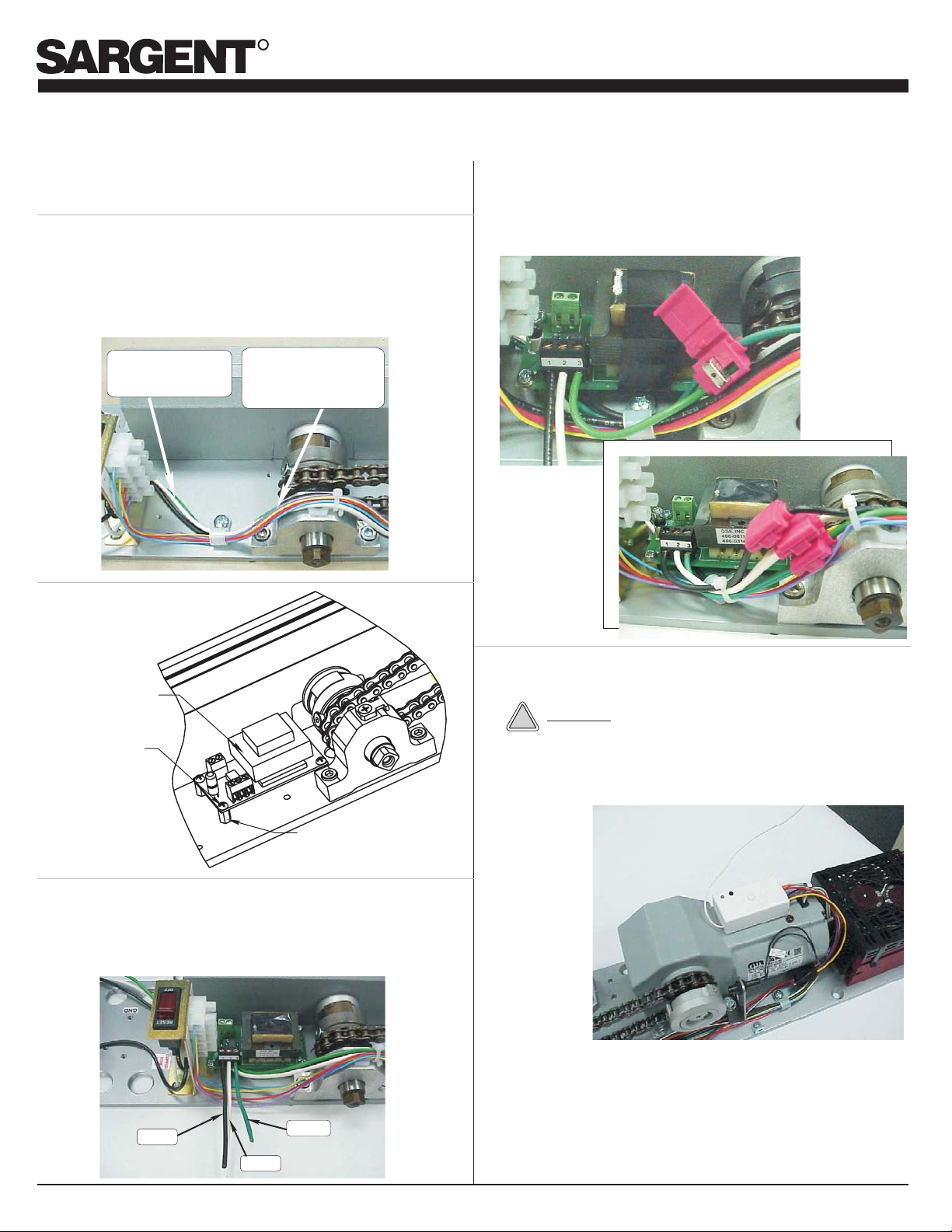
Step 1. Toggle circuit breaker to OFF position to terminate power
to unit before proceeding
Step 2. Note the wires that will be spliced into the 120VAC supply
Hot ------------ (Black wire)
Common ----- (White wire)
Earth Ground (Green wire)
Power supply will be mounted on stand offs over top of the
wires shown
Use these wires
for splicing
Pull slack in wires to
this area forTap
Connectors
Step 3. Mount power supply as
illustrated
Step 5. Use the three tap connectors (provided) to splice power
supply leads into units 120VAC power.
Splice Black to Black;White to White; and.Green to
Green
RFR1
Power Supply
24VDC
6-32 x 1/4 “ Phillips
Round Head Screw
(Qty 4)
6-32 x 3/8 Standoff
(Qty 4)
Step 4. Connect (3) short splicing wires (provided) to the three
position terminal on the RFR1 Power Supply
Terminal 1 ----(Black wire)
Terminal 2 ----(White wire)
Terminal 3 ----(Green wire)
Step 6. Mount 433MHz Receiver to unit as shown usingVelcro
strip provided
CAUTION
!
Use cable ties (provided) to secure the RF’s wiring
harness to the units existing wiring to insure RF’s wiring
will not come in contact with sprockets or chain
Black
White
An ASSA ABLOY Group company
Green
Page 1
© SARGENT Manufacturing Company 2006
A7872B
Page 2
R
MP3000 Door Operator
RF Kit Kit RFR1Instructions -
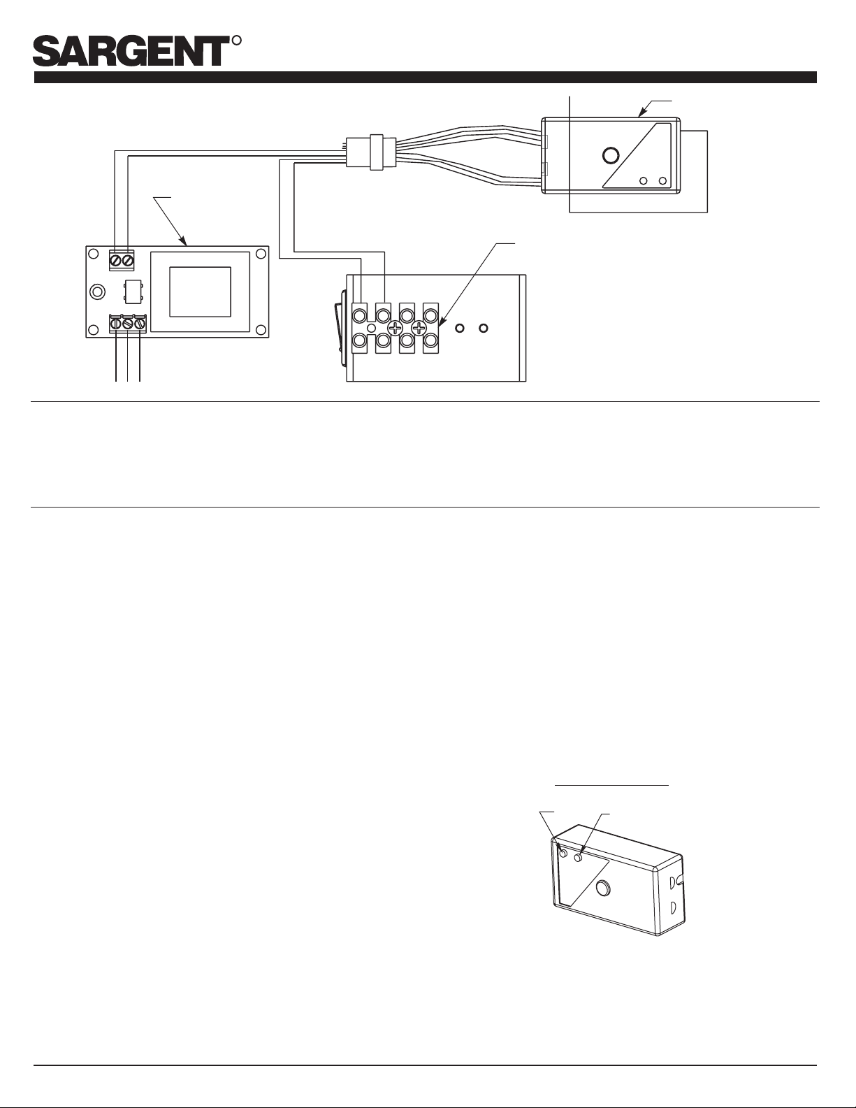
Step 7. Connect wiring harness of 433MHz Receiver to unit as
shown
RFR1
24VDC
Output
BLACKWIRE
Power Supply
RED WIRE
ORANGE WIRE
WIRE
BROWN/WHITE
1
3
12
Black
Green
White
120VAC
Input
1
Step 8. Toggle circuit breaker switch to RESET position to turn
power input to unit on.
Confirm LED on 433MHz Receiver is flashing red.
433MHz Receiver
Terminal Strip
inside MP3000
3
2
2
4
3
4
ProgrammingTransmitter(s) Into 433MHz Receiver Memory
The 433MHz Receiver can learn up to 12 transmitters.
Programming of a 13th transmitter will dump the code
programmedforthefirst transmitterinthesequence.
Follow the directions below to store a transmitter’s code into
the433MHzReceiverlocatedonthedoor operator.
1. Door operator should have input power turned on.
ConfirmLEDon 433MHzReceiverisflashing red.
2. Press 433MHz Receiver’s programming button for less
than 2 seconds and release.The 433MHz Receiver’sLED
changesfromblinkingredtosolidgreen.
3. Press and release the button on a 433MHz FOB (or RF
Wall Switch on any 433MHZ transmitter being
programmedtoactivatetheMP3000) once.Verify433MHz
Receiver’s LED changes to solid red. The 433MHz
Receiveris nowlearningthe transmitter’scode.
4. Waita fewseconds and press and release the same FOB
button(or433MHztransmitter)asinstep3asecondtime.
The433MHzReceiver’sLEDwillblinkgreen severaltimes
indicating it is ending its learning procedure. When it is
ended,the433MHzReceiver LED should resumeblinking
red.
Deleting AllTransmitters from 433MHz Receiver Memory
Youcanclearthe 433MHz Receivermemoryofallpreviously
learnedtransmitters.
1. Press the 433MHz Receiver’s programming button for
more than 8 seconds until the LED starts blinking green.
Release the programming button. The LED should now
beblinking red.
2. The 433MHzReceiver’s memory in nowcleared. Tolearn
new transmitters, follow the steps for programming
transmittersintothe433MHzReceiver’smemory.
433MHz Receiver
LED
Programming
Button
80-9357-1970-021 (09-06) Page 2
© SARGENT Manufacturing Company 2006
A7872B
 Loading...