

Page 1
Any and all SANYO products described or contained herein do not have specifications that can handle
applications that require extremely high levels of reliability, such as life-support systems, aircraft’s
control systems, or other applications whose failure can be reasonably expected to result in serious
physical and/or material damage. Consult with your SANYO representative nearest you before using
any SANYO products described or contained herein in such applications.
SANYO assumes no responsibility for equipment failures that result from using products at values that
exceed, even momentarily, rated values (such as maximum ratings, operating condition ranges,or other
parameters) listed in products specifications of any and all SANYO products described or contained
herein.
CMOS IC
4-bit Microcontroller
with Built-in EPROM and LCD Drivers
Ordering number:ENN3410C
LC58E68
SANYO Electric Co.,Ltd. Semiconductor Company
TOKYO OFFICE Tokyo Bldg., 1-10, 1 Chome, Ueno, Taito-ku, TOKYO, 110-8534 JAPAN
Overview
The LC58E68 is a 4-bit microcontroller with built-in 16
Kbytes of EPROM, 1 Kbit of RAM and LCD drivers. It
can perform most of the functions of the LC586X series
single-chip microcontroller, making it ideal for prototyping
systems based on these devices.
The LC58E68 features an additional 224 bytes of EPROM
containing the configuration option data. Configuration
options include input and output configurations and osillator
selection. Input configuration are LOW-level hold transistor, HIGH-level hold transistor and no hold transistor enabled, and pull-up and pull-down input transistors. Output
configuration options are LCD driver and CMOS, p-channel open-drain and n-channel open-drain general-purpose
outputs.The osillator options are ceramic filter, crystal, and
both ceramic filter and crystal.
The LC58E68’s UV-erasable EPROM can be reprogrammed using a general-purpose PROM programmer and
an adapter board.
The LC58E68 operates from a 3 or 5 V supply and is available in 80-pin QIPs.
Features
• Compatible with the LC586X series mask ROM devices
• 16-Kbyte program EPROM
• 224-byte configuration EPROM
• 1-Kbit RAM
• LCD drivers
• 3 or 5 V supply
• 80-pin QIP
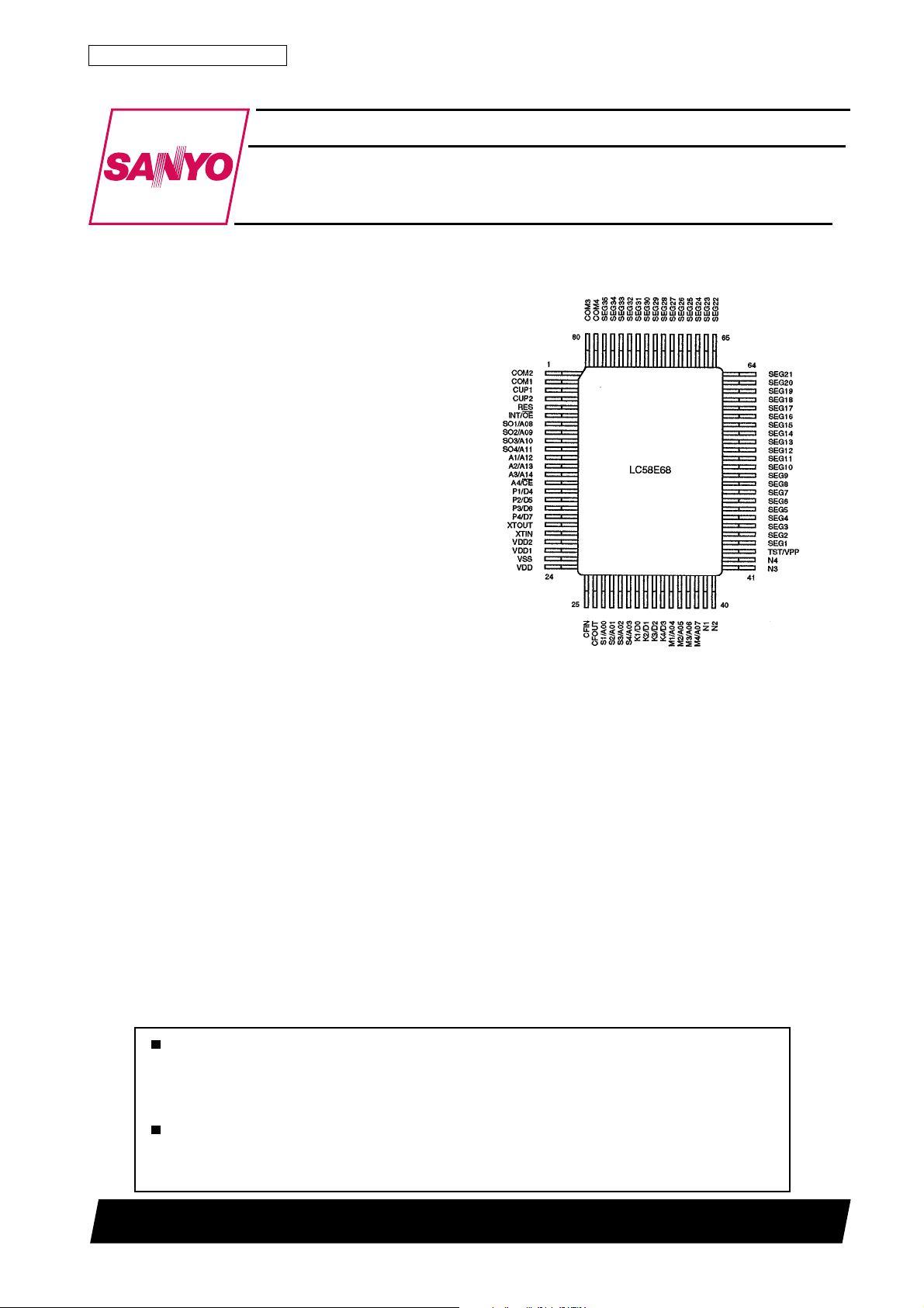
Pin Assignment
Top view
O2501TN(KT)/11795TH (ID)/7142JN No.3410–1/16
Page 2
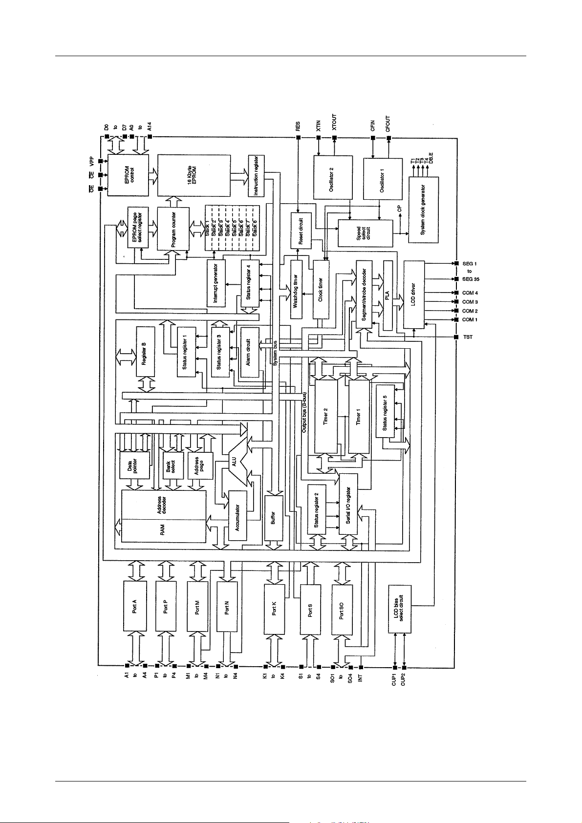
Block Diagram
LB58E68
No.3410–2/16
Page 3

Pin Function
rebmuNemaN noitcnuF
12MOC
21MOC
31PUC
42PUC
5SERtupniteserHGIH-evitcA
6EO/TNI tupni)EO(elbanetuptuoMORPEdna)TNI(tseuqertpurretnidexelpitluM
780A/1OS
890A/2OS
901A/3OS
0111A/4OS
1121A/1A
2131A/2A
3141A/3A
41EC/4A
514D/1P
615D/2P
716D/3P
817D/4P
91TUOTX
02NITX
12V
22V
32VSSdnuorG
42V
52NIFC
62TUOFC
7200A/1S
8210A/2S
9220A/3S
0330A/4S
130D/1K
231D/2K
332D/3K
433D/4K
5340A/1M
6350A/2M
7360A/3M
8370A/4M
931N
042N
143N
244N
34PPV/TSTVMORPEdna)TST(tupnitsetdexelpitluM
87ot4453GESot1GESstuptuoesorup-larenegrosrevirdtnemgesDCL
974MOC
083MOC
LB58E68
stuptuonommocDCL
snoitcennocroticapactiucricsaibevirdDCL
)11A
)7Dot4D(senilsubatadMORPEdna)4Pot1P(Ptroptuptuo/tupnitib-4dexelpitluM
snoitcennocrotallicsolatsyrC
2
DD
1
DD
DD
ylppusegatloV
)4Mdna3M(stupnikcolc
stuptuonommocDCL
noitcennocroticapacylppussaibevirdDCL
snoitcennocrotallicsoretlifcimareC
)30Aot00A(stupnisserddaMORPEdna)4Sot1S(Stroptupnitib-4dexelpitluM
)3Dot0D(senilsubatadMORPEdna)4Kot1K(Ktroptuptuo/tupnitib-4dexelpitluM
)4N(tuptuolangismraladna)4Not1N(Ntroptuptuoniardnepo,tib-4dexelpitluM
PP
)PPV(ylppus
ot8OA(stupnisserddaMORPEdna)3OSotOS(troplaires,)4OSot1OS(OStroptuptuo/tupnitib-4dexelpitluM
)EC(tupnielbanepihcdna)41Aot21A(stupnisserddaMORPE,)4Aot1A(Atroptuptuo/tupnitib-4dexelpitluM
lanretxe2dna1remitdna)70Aot40A(stupnisserddaMORPE,)4Mot1M(Mtroptuptuo/tupnitib-4dexelpitluM
No.3410–3/16
Page 4
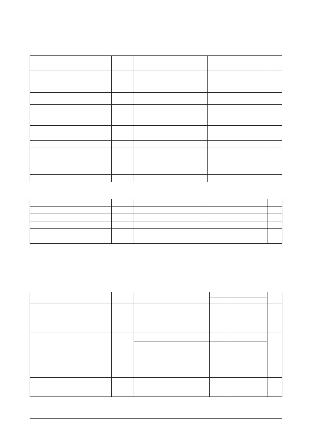
Specifications
Absolute Maximum Ratings
retemaraPlobmySsnoitidnoCsgnitaRtinU
egatlovylppuSV
1egatlovylppusDCLV
2egatlovylppusDCLV
egnaregatlovtupniNIFCdnaNITXV
egnaregatlovtupniTST
egnar
egnartnerructuptuoNstroPI
egnartnerructuptuolatot53
noitapissidrewopelbawollAxamdP 005Wm
erutarepmetgnitarepOrpoT 04ot01°C
erutarepmetegarotSgtsT 521+ot55–°C
LB58E68
xam 0.6+ot3.0–V
DD
1DD
2DD
1I
dnaTNI,SERdna,AdnaOS,P,K,SstroP
egnaregatlovtuptuoTUOFCdnaTUOTXV
egnaregatlovtuptuoniard-nepoNstroPV
egnartnerructuptuoAdnaOS,M,P,KstroPI
V
2I
1O
1GES,2PUC,1PUCdna,AdnaOS,P,KstroP
egatlovtuptuo4MOCot1MOCdna53GESot
V
2O
3O
1O
2O
GESot1GESdna,NdnaA,OS,M,P,KstroP
∑I
O
Vot3.0–
V
DD
Vot3.0–
V
DD
egatlovdetarenegmumixamot0V
Vot3.0–
3.0+V
DD
egatlovdetarenegmumixamot0V
Vot3.0–
3.0+V
DD
31+ot3.0–V
51+ot01–Am
5+ot5–Am
07+ot07–Am
Allowable Operating Ratings at Ta = 25˚C
retemaraPlobmySsnoitidnoCsgnitaRtinU
delbasidDCLhtiwegnaregatlovylppuSV
saibcitatshtiwegnaregatlovylppuSV
saib-2/1htiwegnaregatlovylppuSV
saib-3/1htiwegnaregatlovylppuSV
egatlovnoitneteratadmuminiMV
DD
DD
DD
DD
RD
1etoneeS 5.5ot8.2V
1etoneeS 5.5ot8.2V
2etoneeS 5.5ot8.2V
3etoneeS 5.5ot8.2V
4etoneeSot8.2VDDV
Notes
1. V
DD1=VDD2=VDD
2. V
DD1=VDD2
3. V
DD1
≈1/2×V
≈2/3×VDD, V
DD
DD2
≈1/3×V
DD
4. Oscillator and all internal circuits halted
Electrical Characteristics at Ta = 25˚C, VDD=2.8 to 3.2V
retemaraPlobmySsnoitidnoC
V
DD
f
1egatlovylppusDCLV
2egatlovylppusDCLV
tnerrucylppuSI
tnerrucegakaelylppuSI
-woltupniTNIdna,AdnaOS,M,P,K,SstroP
egatlovlevel
egatlovlevel
DD
DD
V
1LI
-hgihtupniTNIdna,AdnaOS,M,P,K,SstroP
V
1HI
1DD
2DD
latx
V
DD
f
latx
V
DD
f
latx
V
DD
V
DD
Zck52= Ω .4erugifeeS.saib-3/1,edomtlah,
V
DD
V
DD
V
DD
f,V3=
f,V3=
f,V3=
f,V3=
sgnitaR
nimpytxam
,saib-2/1,Fµ1.0=2C=1C,V3=
.2erugifeeS.zHk867.23=
,saib-3/1,Fµ1.0=2C=1C,V3=
.3erugifeeS.zHk867.23=
,saib-3/1,Fµ1.0=2C=1C,V3=
.3erugifeeS.zHk867.23=
C,zHk23=
latx
latx
rec
rec
C,zHk004=
.5erugifeeS.edomtlah
C,zHM1=
.6erugifeeS.edomtlah
g
gcC=dc
gcC=dc
Z,Fp02=
k52= Ω,
c
.4erugifeeS.saib-3/1,edomtlah
C,zHk56ro83=
,Fp01=
g
,Fp033=
,Fp001=
.1erugifeeS.edomybdnats,V3=1Aµ
03.0VDDV
V7.0
DD
5.1
0.1
0.2V
5
01
051
002
V
DD
tinU
V
Aµ
V
Continued on next page
No.3410–4/16
Page 5

Continued from preceding page
retemaraPlobmySsnoitidnoC
egatlov
egatlov
tnerruc
egatlovlevel-woltuptuoNtroPV
tnerrucegakaeltuptuoNtroPI
egatlov
egatlov
tnerruc
egatlov
tnerruc
egatlov
egatlov
egatlov
egatlov
egatlov
egatlov
egatlov
egatlov
egatlov
egatlov
egatlov
egatlov
egatlov
ecnatsisertupnirotsisnart
ecnatsisertupnirotsisnart
ecnatsisertupni
ecnatsisertupni
LB58E68
egatlovlevel-woltupniNIFCdnaSERV
egatlovlevel-hgihtupniNIFCdnaSERV
level-woltuptuoAdnaOS,M,P,KstroP
level-hgihtuptuoAdnaOS,M,P,KstroP
egakaeltupniTNIdna,AdnaOS,M,K,SstroP
egatlovlevel-woltuptuoSOMC53GESot1GESV
level-hgihtuptuoSOMC53GESot1GES
level-hgihtuptuolennahc-p53GESot1GES
egakaeltuptuolennahc-p53GESot1GES
level-woltuptuolennahc-n53GESot1GES
egakaeltuptuolennahc-n53GESot1GES
level-woltuptuo53GESot1GESsaib-citatS
level-hgihtuptuo53GESot1GESsaib-citatS
egatlovlevel-woltuptuo1MOCsaib-citatSV
egatlovlevel-hgihtuptuo1MOCsaib-citatSV
level-woltuptuo53GESot1GESsaib-2/1
level-hgihtuptuo53GESot1GESsaib-2/1
level-woltuptuo4MOCot1MOCsaib-2/1
level-dimtuptuo4MOCot1MOCsaib-2/1
level-hgihtuptuo4MOCot1MOCsaib-2/1
level-woltuptuo53GESot1GESsaib-3/1
level-dimtuptuo53GESot1GESsaib-3/1
level-hgihtuptuo53GESot1GESsaib-3/1
level-woltuptuo4MOCot1MOCsaib-3/1
level-dimtuptuo4MOCot1MOCsaib-3/1
level-hgihtuptuo4MOCot1MOCsaib-3/1
dlohlevel-wolAdnaOS,M,P,K,SstroP
dlohlevel-hgihAdnaOS,M,P,K,SstroP
rotsisnartpu-llupAdnaOS,M,P,K,SstroP
rotsisnartnwod-llupAdnaOS,M,P,K,SstroP
ecnatsisertupnirotsisnartdlohlevel-wolTNIR
ecnatsisertupnirotsisnartdlohlevel-hgihTNIR
2LI
2HI
V
V
I
V
V
I
V
I
V
V
V
V
V
V
V
V
V
V
V
V
V
R
R
R
R
I
2LO
I
1HO
VDDV3=
1kael
I
1LO
V
2kael
I
3LO
I
2HO
I
3HO
VLOV0= 1Aµ
3kael
I
4LO
VHOV=
4kael
I
5LO
I
4HO
I
6LO
I
5HO
I
7LO
I
6HO
I
8LO
I
1MO
I
7HO
I
9LO
I
2MO
I
I
8HO
I
01LO
I
3MO
I
I
9HO
VIV2.0=
1LI
VIV8.0=
1HI
VIV=
1UP
VIV=
1DP
VIV2.0=
2LI
VIV8.0=
2HI
Aµ004=2.05.0V
LO
Aµ004–=V
HO
VIV=
SS
VIV=
DD
Am01= 5.0V
LO
V5.01= 1Aµ
HO
Aµ001= 5.0V
LO
Aµ001–=V
HO
Aµ001–=V
HO
Aµ001= 5.0V
LO
DD
Aµ02= 2.0V
LO
Aµ02–=V
HO
Aµ001= 2.0V
LO
Aµ001–=V
HO
Aµ02= 2.0V
LO
Aµ02–=V
HO
Aµ001= 2.0V
LO
LO
HO
LO
LO
LO
HO
LO
LO
LO
HO
IroAµ001=
Aµ001–=V
Aµ02= 2.0V
IroAµ02=
HO
IroAµ02=
HO
Aµ02–=V
Aµ001= 2.0V
IroAµ001=
IroAµ001=
Aµ001–=V
DD
DD
SS
DD
DD
DD
Aµ001–=
HO
Aµ02–=
Aµ02–=
Aµ001–=
HO
Aµ001–=
HO
sgnitaR
nimpytxam
052.0VDDV
V57.0
DD
5.0–VDD2.0–V
DD
1–
5.0–V
DD
5.0–V
DD
2.0–V
DD
2.0–V
DD
2.0–V
DD
V(
)2/
DD
2.0–
2.0–V
DD
V(
)3/
DD
2.0–
V3/2(
)
DD
2.0–
2.0–V
DD
V(
)3/
DD
2.0–
V3/2(
)
DD
2.0–
2.0–V
DD
060030021kΩ
060030021kΩ
03051005kΩ
03051005kΩ
060030021kΩ
060030021kΩ
V
DD
V(
DD
V(
DD
V3/2(
V(
DD
V3/2(
1
1Aµ
)2/
2.0+
)3/
2.0+
)
DD
2.0+
)3/
2.0+
)
DD
2.0+
tinU
V
Aµ
V
V
V
V
V
Continued on next page
No.3410–5/16
Page 6

LB58E68
Continued from preceding page
retemaraPlobmySsnoitidnoC
ecnatsiserrotsisnartpu-llupTNIR
ecnatsiserrotsisnartnwod-llupTNIR
ecnatsiserrotsisnartnwod-llupTSTR
ecnaticapacgnitasnepmocnoitallicsoTUOTXC
ycneuqerfgnitareporotallicsolatsyrCf
ycneuqerfgnitareporotallicsoretlifcimareCf
ycneuqerfkcolcecafretnilaireSf
Electrical Characteristics at Ta = 25˚C, VDD=4.5 to 5.5V
retemaraPlobmySsnoitidnoC
1egatlovylppusDCLV
2egatlovylppusDCLV
tnerrucylppuSI
tnerrucegakaelylppuSI
egatlovlevel-woltupni
egatlovlevel-hgihtupni
egatlov
egatlov
tnerruc
egatlov
egatlov
tnerruc
egatlov
tnerruc
TNIdna,AdnaOS,M,P,K,SstroP
TNIdna,AdnaOS,M,P,K,SstroP
egatlovlevel-woltupniNIFCdnaSERV
egatlovlevel-hgihtupniNIFCdnaSERV
level-woltuptuoAdnaOS,M,P,KstroP
level-hgihtuptuoAdnaOS,M,P,KstroP
egatlovtuptuolevel-WOLNtroPV
tnerrucegakaeltuptuoNtroPI
level-hgihtuptuoSOMC53GESot1GES
level-hgihtuptuolennahc-p53GESot1GES
egakaeltuptuolennahc-p53GESot1GES
level-woltuptuolennahc-n53GESot1GES
egakaeltuptuolennahc-n53GESot1GES
V
V
V
V
egakaeltupniTNIdna,AdnaOS,M,K,SstroP
I
egatlovlevel-woltuptuoSOMC53GESot1GESV
V
V
I
V
I
VIV=
2UP
2DP
3DP
d
latx
rec
res
1DD
2DD
DD
DD
1LI
1HI
2LI
2HI
2LO
1HO
1kael
1LO
2kael
3LO
2HO
3HO
3kael
4LO
4kael
SS
VIV=
DD
VIV=
DD
VDDV3=02Fp
egnarzHk232333
egnarzHk560607
emitllaf/esiR ≤ sµ010002zHk
V
DD
f
latx
V
DD
f
latx
V
DD
f
latx
V
V
Zck52= Ω .4erugifeeS.saib-3/1,edomtlah,
V
V
V
V
V
I
I
V
I
V
I
I
I
VLOV0= 1Aµ
I
VHOV=
f,V5=
DD
f,V5=
DD
f,V5=
DD
f,V5=
DD
f,V5=
DD
f,V5=
DD
DD
Am2=2.05.0V
LO
Am1–=V
HO
V5.5=
DD
Am01= 5.0V
LO
V5.01= 1Aµ
HO
Aµ052= 5.0V
LO
Aµ052–=V
HO
Aµ052–=V
HO
Aµ052= 5.0V
LO
DD
sgnitaR
nimpytxam
00300510005kΩ
00300510005kΩ
0207003kΩ
0910021zHk
sgnitaR
nimpytxam
,saib-2/1,Fµ1.0=2C=1C,V5=
.2erugifeeS.zHk867.23=
,saib-3/1,Fµ1.0=2C=1C,V5=
.3erugifeeS.zHk867.23=
,saib-3/1,Fµ1.0=2C=1C,V5=
.3erugifeeS.zHk867.23=
C,zHk23=
latx
latx
rec
rec
rec
rec
C,zHk004=
.5erugifeeS.edomtlah
C,zHM1=
.6erugifeeS.edomtlah
C,zHM2=
.6erugifeeS.edomtlah
C,zHM4=
.6erugifeeS.edomtlah
VIV=
VIV=
g
gcC=dc
gcC=dc
gcC=dc
gcC=dc
Z,Fp02=
k52= Ω,
c
.4erugifeeS.saib-3/1,edomtlah
C,zHk56ro83=
,Fp01=
g
,Fp033=
,Fp001=
,Fp33=
,Fp33=
.1erugifeeS.edomybdnats,V5.5=1Aµ
03.0VDDV
V7.0
DD
052.0VDDV
V57.0
DD
5.0–VDD2.0–V
DD
SS
DD
1–
5.0–V
DD
5.0–V
DD
5.2
76.1
33.3V
02
03
004
054
005
007
V
DD
V
DD
1
1Aµ
tinU
zHkegnarzHk837393
tinU
V
Aµ
V
V
Aµ
Continued on next page
No.3410–6/16
Page 7

Continued from preceding page
retemaraPlobmySsnoitidnoC
egatlov
egatlov
egatlov
egatlov
egatlov
egatlov
egatlov
egatlov
egatlov
egatlov
egatlov
egatlov
egatlov
ecnatsisertupnirotsisnart
ecnatsisertupnirotsisnart
ecnatsisertupni
ecnatsisertupni
LB58E68
level-wol-tuptuo53GESot1GESsaib-citatS
V
level-hgihtuptuo53GESot1GESsaib-citatS
V
egatlovlevel-woltuptuo1MOCsaib-citatSV
egatlovlevel-hgihtuptuo1MOCsaib-citatSV
level-woltuptuo53GESot1GESsaib-2/1
level-hgihtuptuo53GESot1GESsaib-2/1
level-woltuptuo4MOCot1MOCsaib-2/1
level-dimtuptuo4MOCot1MOCsaib-2/1
level-hgihtuptuo4MOCot1MOCsaib-2/1
level-woltuptuo53GESot1GESsaib-3/1
level-dimtuptuo53GESot1GESsaib-3/1
level-hgihtuptuo53GESot1GESsaib-3/1
level-woltuptuo4MOCot1MOCsaib-3/1
level-dimtuptuo4MOCot1MOCsaib-3/1
level-hgihtuptuo4MOCot1MOCsaib-3/1
dlohlevel-wolAdnaOS,M,P,K,SstroP
dlohlevel-hgihAdnaOS,M,P,K,SstroP
ecnatsisertupnirotsisnartdlohlevel-wolTNIR
ecnatsiserrotsisnartpu-llupTNIR
ecnatsiserrotsisnartnwod-llupTNIR
ecnatsiserrotsisnartnwod-llupTSTR
ycneuqerfgnitareporotallicsolatsyrCf
ycneuqerfgnitareporotallicsoretlifcimareCf
ycneuqerfkcolcecafretnilaireSf
V
V
V
V
V
V
V
V
V
V
V
R
R
rotsisnartpu-llupAdnaOS,M,P,K,SstroP
R
rotsisnartnwod-llupAdnaOS,M,P,K,SstroP
R
ecnatsisertupnirotsisnartdlohlevel-hgihTNIR
ecnaticapacgnitasnepmocnoitallicsoTUOTXC
I
5LO
4HO
6LO
5HO
7LO
6HO
8LO
1MO
7HO
9LO
2MO
8HO
01LO
3MO
9HO
1LI
1HI
1UP
1DP
2LI
2HI
2UP
2DP
3DP
d
latx
rec
res
Aµ02= 2.0V
LO
I
I
I
I
I
I
I
I
I
I
I
I
I
I
I
I
VIV2.0=
VIV8.0=
VIV=
VIV=
VIV2.0=
VIV8.0=
VIV=
VIV=
VIV=
VDDV5=02Fp
Aµ02–=V
HO
Aµ002= 2.0V
LO
Aµ002–=V
HO
Aµ02= 2.0V
LO
Aµ02–=V
HO
Aµ002= 2.0V
LO
LO
HO
LO
LO
LO
HO
LO
LO
LO
HO
IroAµ002=
Aµ002–=V
Aµ02= 2.0V
IroAµ02=
HO
IroAµ02=
HO
Aµ02–=V
Aµ002= 2.0V
IroAµ002=
IroAµ002=
Aµ002–=V
DD
DD
SS
DD
DD
DD
SS
DD
DD
egnarzHk232333
egnarzHk560607
emitllaf/esiR ≤ sµ010002zHk
Aµ002–=
HO
Aµ02–=
Aµ02–=
Aµ002–=
HO
Aµ002–=
HO
sgnitaR
nimpytxam
2.0–V
DD
2.0–V
DD
2.0–V
DD
V(
)2/
DD
2.0–
2.0–V
DD
V(
)3/
DD
2.0–
V3/2(
)
DD
2.0–
2.0–V
DD
V(
)3/
DD
2.0–
V3/2(
)
DD
2.0–
2.0–V
DD
03021005kΩ
03021005kΩ
0105002kΩ
0105002kΩ
03021005kΩ
03021005kΩ
0010050002kΩ
0010050002kΩ
0207003kΩ
0910021zHk
V(
DD
V(
DD
V3/2(
V(
DD
V3/2(
tinU
)2/
V
2.0+
)3/
V
2.0+
)
DD
V
2.0+
)3/
V
2.0+
)
DD
V
2.0+
zHkegnarzHk837393
No.3410–7/16
Page 8

Measurement Circuits
The following conditions apply to figure 1.
• Standby mode
• Port S input resistors enable
• I/O ports in output mode, all outputs HIGH
• INT open and internal input transistors enabled
• External pull-down resistor connected to RES.
• Current flow through components connected to LCD
ports is not included.
• f
= 32 to 65 kHz
xtal
• f
= 200 kHz to 4 MHz
cer
The flowing conditions apply to figures 2 and 3.
• f
= 32 kHz
xtal
• C1 = C2 = C3 = 0.1µF
• LCD ports are open.
• f
= 200 kHz to 4 MHz
cer
LB58E68
Figure 1. Supply leakage measurement Figure 4. Supply current measurement 1
Notes
1. Ceramic filter oscillator stopped
2. f
= 32, 38 or 65kHz
xtal
Figure 2. Supply voltage measurement 1
Figure 5. Supply current measurement 2
Figure 3. Output voltage measurement 2
Figure 6. Supply current measurement 3
Note
Crystal oscillator stopped
No.3410–8/16
Page 9

Pin Functions
emaN noitcnuF
1MOC
2MOC
3MOC
4MOC
1PUC
2PUC
SER .rotsisertupnilanretxenaseriuqerSER.rellortnocorcimehttesersµ002nahtretaergshtdiweslupSER
EO/TNI .desserddasiMORPEehtnehwtupnielbanetuptuoehtsasnoitcnufTNI
80A/1OS
90A/2OS
01A/3OS
11A/4OS
21A/1A
31A/2A
41A/3A
EC/4A
4D/1P
5D/2P
6D/3P
7D/4P
NITX
TUOTX
V
1DD
LB58E68
.wolebelbatehtninwohsera
ylcycytuD1MOC2MOC3MOC4MOC
citatS–––23
2/1––23
3/1 –7.24
4/1 23
etoN
φ
0
V
DD
zHk867.23=
.nepomehtevaelesiwrehto,snipesehtneewteb
.erawtfos
.desserddasiMORPEehtnehwtupnielbanepihcehtdnastupnisubsserddasasnoitcnufAtroP
.desserddasiMORPEehtnehwsenilsubatadsasnoitcnufPtroP
.nepotfelerayehtesiwrehto,snoitcennocrotallicsolatsyrcehtsanoitcufTUOTXdnaNITX
.noitcurtsniDLOHaretfastlahrotallicsoehT.noitponoitarugifnocsiycneuqerflatsyrcehT
Vdna1
DD
.wolebnwohssasnipesehttcennoc
saibcitatSsaib-2/1saib-3/1
,evirdsaibhcaeroF.snoitcennocroticapactiucricsaibevirdDCLsanoitcnuf2
elcycytudhcaerofycneuqrfemarfdnastuptuoevitcaehT.stuptuorevirdnommocDCLsanoitcnuf4MOCot1MOC
emarF
ycneuqerF
)zH(
roticapacralopibatcennoc,saib-3/1ro-2/1gnisunehW.tiucricredividegatlovevird-DCLehtfostrapera2PUCdna1PUC
2OS,tupniatadlairesehtsasnoitcnufosla1OS.desserddasiMORPEehtnehwstupnisubsserddasasnoitcnufOStroP
ybdenimetederaytiralopdnanoitceridkcolC.tuptuorotupnikcolcatadlairesehtsa3OSdnatuptuoatadlairesehtsa
V
2DD
NIFC
TUOFC
00A/1S
10A/2S
20A/3S
30A/4S
0D/1K
1D/2K
2D/3K
3D/4K
.noitcurtsniWOLSro
ta(sm8.7ro59.1 φ
0
.yaledecnuobedStropehtsaemasehtsidoirepyaledehT
.erawtfosybdetcelessidoirepyaledecnuobed)zHk867.23=
DLOHaretfastlahrotallicsoehT.nepotfelerayehtesiwrehto,snoitcennocretlifcimarecehtsanoitcnufTUOFCdnaNIFC
ehT.stiucricecnuobed-yeklanretnievahsnipStrop.desserddasiMORPEehtnehwstupnisubsserddasasnoitcnufStroP
.stiucricecnuobed-yektupnilanretnievahsnipKtroP.desserddasiMORPEehtnehwsenilsubatadsasnoitcnufKtroP
Continued on next page
No.3410–9/16
Page 10

Continued from preceding page
emaN noitcnuF
40A/1M
50A/2M
60A/3M
70A/4M
1N
2N
3N
4N
PPV/TST .dnuorgotdetcennocyllamronsitI.desserddasiMORPEehtnehwtupniPPVehtsasnoitcnufTST
53GESot1GES
.snoitponoitarugifnoc
ta(zHk4ro,2,1ehtsasnoitcnuf4N φ
0
Configuration Options
Oscillator
The oscillator options are ceramic filter, crystal, and
both ceramic filter and crystal. When the crystal oscillator is used, the oscillator frequency options are 32,
38 or 65 kHz. The ceramic filter and crystal oscillator
options are shown in figures 7 and 8, respectively.
LB58E68
2remitsa4Mdna,1remitsasnoitcnufosla3M.desserddasiMORPEehtnehwstupnisubsserddasasnoitcnufMtroP
.emitelcycehtelbuodsidoirepkcolclanretxemuminimehT.3edomnierasremitehtnehwstupnikcolclanretxe
.)WOLsihctaltuptuo4Nehtnehw(tuptuolangismrala)zHk867.23=
sateserastuptuolaudividnifonoitcnufehT.stuptuoesoprup-larenegrosrevirdtnemgesDCLsanoitcnuf53GESot1GES
Figure 8. Crystal oscillatorFigure 7. Ceramic filter oscillator
No.3410–10/16
Page 11

Input Ports
Ports S, K, P, SO and A input options are hold transistor and input transistor configurations as shown in f igure 9. The hold transistor options are LOW-level hold
transistor, HIGH-lev el hold transistor and no hold transistor enabled, The input options are pull-up and pulldown transistors enabled.
Figure 9. Ports S, K, P, SO and A input circuit
Note : Cofiguration data determines switch settings.
LB58E68
Figure 11. n-channel output
The output latch state of all LCD drivers and generalpurpose outputs can be reset in standby mode. The options are reset and no change.
Port N
Port N outputs are n-channel open-drain as shown in figure 12.
Outputs
SEG1 to SEG35
The SEG1 to SEG35 options are LCD driver or generalpurpose outputs, LCD driver bias and duty configiration,
general-purpose output configuration and output latch
state in STOP mode. The LCD driver and general-purpose output function selection is hard coded in the PLA
and, therefore, cannot be selected by software.
The LCD driver bias and duty configuration is set for all
LCD drivers. The configuration options are follows.
• Static
• 1/2-bias and 1/2-duty
• 1/2-bias and 1/3-duty
• 1/2-bias and 1/4-duty
• 1/3-bias and 1/3-duty
• 1/3-bias and 1/4-duty
The general-purpose output configuration is set for individual outputs. The options are CMOS, p-channel opendrain and n-channel open-drain. The p-channel and nchannel output equivalent circuits are shown in figures
10 and 11, respectively.
Figure 12. Ports N open-drain outputs
Serial Data Clock
The SO3 clock divider ratio options are 1/1, 1/2 and 1/4.
Interrupt Request
The interrupt request input options are hold transistor,
input transistor and interrupt request trigger configurations. The input hold transistor and input transistor options are the same as for the port inputs. The interrupt
request trigger options are rising-edge and falling-edge
triggering.
Figure 10. p-channel output
No.3410–11/16
Page 12

Design Information
Development Process
The LC5860 series software development tools,
EC5868.EXE software and a general-purpose PROM
programmer with a W58E68Q adapter board are re-
LB58E68
quired for LC58E68 program development. The de velopment flowchart is shown in figure 13.
Figure 13. Development flowchart
No.3410–12/16
Page 13

LC586X series software development tools
These tools are used on an MS-DOS computer to create programs and option data. See the LC586X series
development tools manual for further infomation.
EC5868.EXE
This program combines an LC586X series program with
the configuration option data generated by the option
LC5862H, 63H, 64H LC5866H, 68H
LB58E68
data software and converts the result to LC58E68 EPR OM
downloading format as shown in figure 14.
Figure 14. Conversion to EPROM format
No.3410–13/16
Page 14

LB58E68
For example, to con v ert the ROMSAMP.HXE program
file and the PLASAMP.HEX option data file into the
EP-SAMP.HEX download-format file, enter one of the
following commands at the command line:
A : >EC5868 ROMSAMP.HEX PLASAMP.HEX EP–SAMP.HEX ↵
or
A : >EC5868 B:ROMSAMP.HEX B:PLASAMP.HEX C:EP–SAMP.HEX ↵
or
A : >EC5868↵
****************************************************************
* LC58E68 PROGRAM & MASK OPTION CONVERSION Ver XXXX *
****************************************************************
A : ROM PROGRAM NAME : B:ROMSAMP.HEX ↵
A : PLA PROGRAM NAME : B:PLASAMP.HEX ↵
A : EP ROM WRITE NAME : B:EP-SAMP.HEX ↵
A program completion message is output at the end of
conversion.
If an error occurs, the program will issue one of the
following error messagees.
Note that the programmer provided with the EVA-520
and EVA-850 development tools cannot be used. Set the
programmer for a 256 Kbyte PROM, V
gram addresses 0000H to 40FFH.
The W58E68Q adapter board, shown in figure 15, is
• Error ON filename.HEX, FILE NOT FOUND
The file filename.HEX was not found or the f ile name
placed in the PROM programmer socket and the
LC58E68 to be programmed, in the W58E68Q adapter.
was incorrect.
• Error ON, MAKE LC5864H, 63H, 62H
The ROM data and option data are not consistent.The
cross assembler and option data software used should
be for the same device.
• Error ON filename.HEX, EOF NOT DETECTED
The file filename.HEX does not have a record end
marker or the file is corrupted.
• Error ON filename.HEX, ILLEGAL CHARACTER
The file filename.HEX contains a non-hexadecimal
character.
• Error ON filename.HEX, ADDRESS OVER
An address in the file filename.HEX exceeds the address limit.
• Error ON filename.HEX, ILLEGAL FILE HDR.
The file filename.HEX does not have the correct
LC586X series header or there is an error in the hex
Figure 15. W58E68Q adapter board
file.
• Error ON command line input, INVALID NUMBER
OF PARAMETERS
Affix an opaque seal to the window of the programmed
LC58E68 when not programming the EPROM.
The number of parameters entered on the command
line is incorrect.
• Error ON ILLEGAL, MASK OPTION DATA
The mask option data is incorrect.
Erasing the EPROM
The EPROM data can be erased with a standard UV
EPROM eraser.
=21V and pro-
P–P
PROM programmer and W58E68Q adapter
board
Programming the LC58E68 requires a general-purpose
PROM programmer and a W58E68Q adapter board.
Soldering
Do not use the solder-dip process for soldering the
LC58E68.
No.3410–14/16
Page 15

LB58E68
Reset Timing
The reset state is released following a HIGH-to-LOW
transition on RES. Configuration options and the segment output control PLA are initialized during the next
256 clock cycles. The program counter is then reset and
Ordering Information
T ypically, a mask ROM LC586X series de vice is ordered
after a system has been prototyped with the LC58E68.
However, a programmed LC58E68 or an LC58E68-format hex file cannot be used to specify the mask ROM
device.
When ordering, provide three EPROMs each containing
the mask ROM program generated using a standard as-
Table 1. Electrical characteristics comparison
retemaraPlobmySsnoitidnoC86E85CLseiresX685CLtinU
erutarepmetgnitarepOrpoT04ot0107ot03–°C
egatlovylppuSV
tnerrucylppusedom-tlahlacipyTI
DD
V
V
DD
V
V
V
program execution begins. Configuration options are invalid and segment outputs are held at VSS from when
RES goes HIGH until the options are initialized.
sembler and another three EPROMs each containing the
option data generated using the option specification tool.
A comparison of LC58E68 characteristics with those of
LC586X series mask ROM devices is shown in tables 1
and 2.
5.5ot8.20.6ot0.2V
f,V3=
DD
f,V5=
DD
f,V5=
DD
f,V5=
DD
f,V5=
DD
zHk23=54
latx
zHk23=0251
latx
zHk004=004004
rec
zHM2=005005
rec
zHM4=007007
rec
Aµ
Table 2. Configuration comparison
retemaraP86E85CLsecivedX685CL
tesergnirud
stuptuonommocdnatnemgesDCL
teserretfaetatstuptuotnemgeSdeyalpsidtoN deyalpsidtonrodeyalpsiD
epyttiucricrotallicsO latsyrcdnaretlifcimarecro,latsyrc,retlifcimareC
ycneuqerflatsyrC )tesergnirudzHk56(zHk56ro83,23zHk56ro83,23
tupniteserSERHGIH-evitcA
stuptuoNtroPniard-nepO SOMCroniard-nepO
epytevirdDCL
).1etoneeS(ytud-4/1dna
egnar'.oNebortS').2etoneeS(HE1otH00HE1otH00
VtadleheradnaSOMCerastuptuotnemgeS
.
SS
.niard-nepodnalennahc-nerastuptuonommoC
,ytud-3/1dnasaib-2/1,ytud-2/1dnasaib-2/1,citatS
saib-3/1roytud-3/1dnasaib-3/1,ytud-4/1dnasaib-2/1
noitarepocitatS
CR,latsyrcdnaretlifcimarec,latsyrc,retlifcimareC
rorotallicsolanretxe,latsyrcdnatiucricCR,tiucric
latsyrcdnarotallicsolanretxe
roHGIH-evitca,pu-lluphtiwWOL-evitca,WOL-evitcA
pu-lluphtiwHGIH-evitca
-2/1,ytud-3/1dnasaib-2/1,ytud-2/1dnasaib-2/1,citatS
dnasaib-3/1,ytud-3/1dnasaib-3/1,ytud-4/1dnasaib
desunuroytud-4/1
Notes
1. Configure as static drive if not used.
2. Strobe numbers 00 to 1EH can be used in applications that use a 2 MHz ceramic resonator. Strobe numbers 0E, 0F and
1EH cannot be used in applications that use a 4 MHz ceramic resonator.
No.3410–15/16
Page 16

LB1720
The LC586X series devices, including the LC58E68, are
shown in table 3.
Table 3. LC586X series devices
eciveD)setybk(yticapacMOR)stib(yticapacMARepytegakcaP
H2685CL4652 × 408PIQ
H3685CL6652 × 408PIQ
H4685CL8652 × 408PIQ
H6685CL21652 × 408PIQ
H8685CL61652 × 408PIQ
86E85CL)MORPE(61652 × 408CFQ
Table 4. Recommended ceramic resonators for LC5862H/63H/64H/66H/68H mask ROMs
rerutcafunaM
ycneuqerfrotanoseR
rebmuntraPC
zHk004P004BSC033033B004-RBK033033
zHk008J008BSC022022H008-RBK001001
zHM1J0001BSC022022H0001-RBK001001
zHM2
zHM4
GM00.2ASC
GM00.2TSC
GM00.4ASC
GM00.4TSC
ataruMarecoyK
)Fp(Cdc)Fp(rebmuntraPC
gc
3333SM0.2-RBK3333
3333SM0.4-RBK3333
gc
)Fp(Cdc)Fp(
Specifications of any and all SANYO products described or contained herein stipulate the performance,
characteristics, and functions of the described products in the independent state, and are not guarantees
of the performance, characteristics, and functions of the described products as mounted in the customer's
products or equipment. To verify symptoms and states that cannot be evaluated in an independent device,
the customer should always evaluate and test devices mounted in the customer's products or equipment.
SANYO Electric Co., Ltd. strives to supply high-quality high-reliability products. However, any and all
semiconductor products fail with some probability. It is possible that these probabilistic failures could
give rise to accidents or events that could endanger human lives, that could give rise to smoke or fire,
or that could cause damage to other property. When designing equipment, adopt safety measures so
that these kinds of accidents or events cannot occur. Such measures include but are not limited to protective
circuits and error prevention circuits for safe design, redundant design, and structural design.
In the event that any or all SANYO products(including technical data,services) described or
contained herein are controlled under any of applicable local export control laws and regulations,
such products must not be exported without obtaining the export license from the authorities
concerned in accordance with the above law.
No part of this publication may be reproduced or transmitted in any form or by any means, electronic or
mechanical, including photocopying and recording, or any information storage or retrieval system,
or otherwise, without the prior written permission of SANYO Electric Co. , Ltd.
Any and all information described or contained herein are subject to change without notice due to
product/technology improvement, etc. When designing equipment, refer to the "Delivery Specification"
for the SANYO product that you intend to use.
Information (including circuit diagrams and circuit parameters) herein is for example only ; it is not
guaranteed for volume production. SANYO believes information herein is accurate and reliable, but
no guarantees are made or implied regarding its use or any infringements of intellectual property rights
or other rights of third parties.
This catalog provides information as of October, 2001. Specifications and information herein are subject
to change without notice.
No.3410–16/16
 Loading...