

Page 1
Any and all SANYO products described or contained herein do not have specifications that can handle
applications that require extremely high levels of reliability, such as life-support systems, aircraft’s
control systems, or other applications whose failure can be reasonably expected to result in serious
physical and/or material damage. Consult with your SANYO representative nearest you before using
any SANYO products described or contained herein in such applications.
SANYO assumes no responsibility for equipment failures that result from using products at values that
exceed, even momentarily, rated values (such as maximum ratings, operating condition ranges,or other
parameters) listed in products specifications of any and all SANYO products described or contained
herein.
Monolithic Linear IC
2-Channel Preamplifier For Car Stereo
Ordering number:ENN494F
LA3160
SANYO Electric Co.,Ltd. Semiconductor Company
TOKYO OFFICE Tokyo Bldg., 1-10, 1 Chome, Ueno, Taito-ku, TOKYO, 110-8534 JAPAN
Features
• Two preamplifiers on chip.
• Fewer peripheral parts.
• Low noise.
• 8-pin SIP package facilitating easy mounting.
Specifications
Absolute Maximum Ratings at Ta = 25˚C
retemaraPlobmySsnoitidnoCsgnitaRtinU
egatloVylppuSmumixaMV
noitapissiDrewoPelbawollAxamdP 002Wm
erutarepmeTgnitarepOrpoT 57+ot02–
erutarepmeTegarotSgtsT 521+ot04–
CC
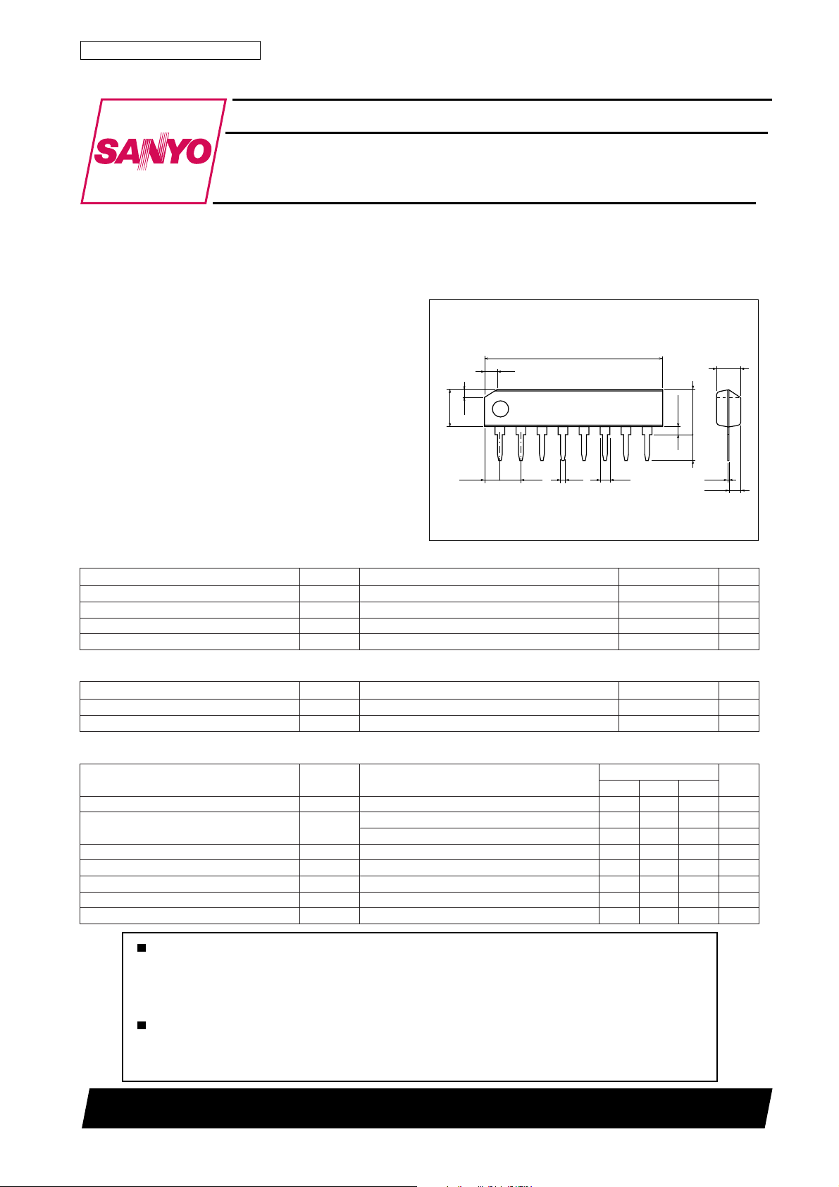
Package Dimensions
unit:mm
3016B-SIP8
[LA3160]
2.54
22.3
0.5
0.51min
8
1.3
SANYO : SIP8
1.5
1.0
4.8
1
2.26
xam 81V
5.7max
3.2
0.25
1.35
3.0
˚C
˚C
Recommended Operating Conditions at Ta = 25˚C
retemaraPlobmySsnoitidnoCsgnitaRtinU
egatloVylppuSV
ecnatsiseRdaoLR
CC
L
Operating Conditions at Ta = 25˚C, VCC=9V, RL=10kΩ, Rg=600Ω, f=1kHz, NAB
retemaraPlobmySsnoitidnoC
noitapissiDtnerruCI
niaGegatloVGV
egatloVtuptuOV
noitrotsiDcinomraHlatoTDHTVOV5.0=1.03.0%
ecnatsiseRtupnIr
egatloVesioNtupnItnelaviuqEV
klatssorCTC05–56–Bd
CC
O
i
IN
pooldesolC53Bd
V,poolnepO
V77.0=6708Bd
O
%1=DHT1.18.1V
k2.2=gR Ω 52.10.2Vµ
11200TH (KT)/N0493TH/7160TS/O137KI/8044KI/8250KI, TS No.494–1/7
sgnitaR
nimpytxam
46Am
k07k001
9V
Ω
k01
tinU
Ω
Page 2
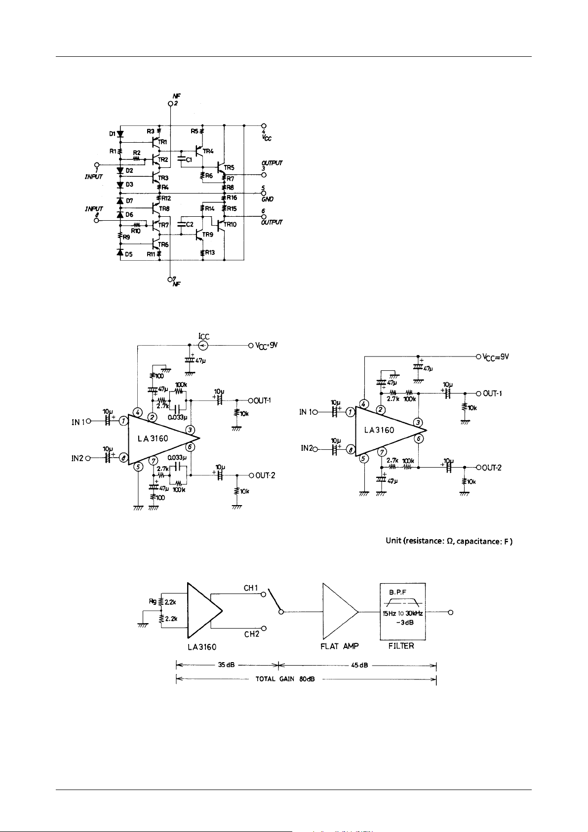
Equivalent Circuit Block Diagram
LA3160
Test Circuit1 : VO, VG, THD, ICC, r
Test Circuit3 : Noise
i
Test Circuit2 : VG
O
No.494–2/7
Page 3
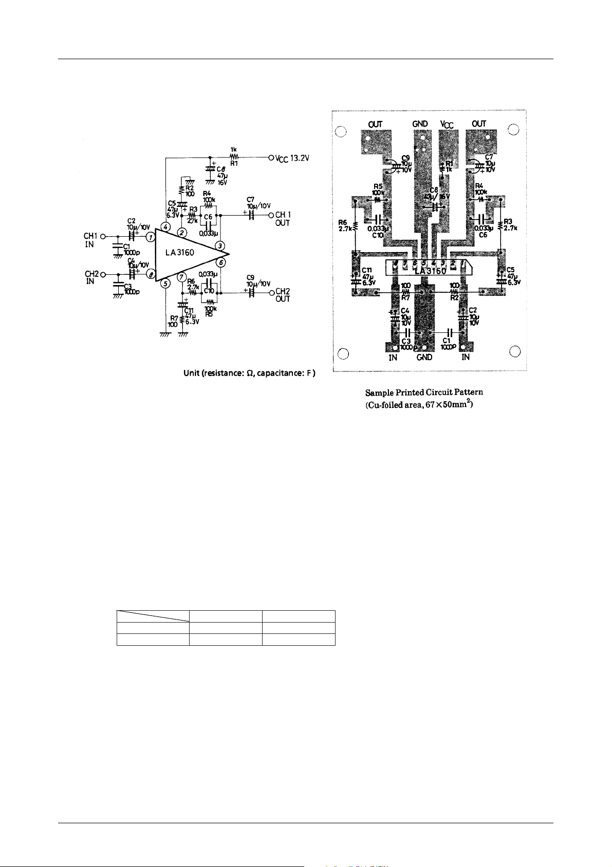
LA3160
Sample Application Circuit 1 : Preamplifier for Car Stereo
Function of External Parts
C2, C4 are input coupling capacitors. In NAB equalizer amplifier, the gain at low frequencies is high and 1/f noise
inside the IC is emphasized as output noise. Therefore, if the reactance of capacitor at low frequencies is increased,
the dependence of 1/f noise on the signal source resistance causes the output noise voltage to deteriorate, and the
value of reactance must be made small enough as compared with the signal source resistance. C2, C4 also influence
the operation start time and the adequate value of these capacitors is 10µF. (Since C2, C4 of less than 4.7µF make the
operation start time longer, use C2, C4 of 4.7µF or more).
C5, C11 are NF capacitors. The lower cut-off frequency depends on the value of these capacitors.
If the lower cut-off frequency is taken as fL :
C5 (C11) = 1/2π · fL · R2 (R7)
If the value of this capacitor is made larger, the operation start time of amplifier is more delayed. The adequate value
of capacitor is 47µF.
The frequency characteristic of the equalizer amplifier depends on C6 and R4, R3 (C10 and R5, R6).
The time constants to obtain the standard NAB characteristic are as shown below.
Tape speed
)4R+3R(6Csµ0813sµ0951
6C3Rsµ09sµ021
s/mc5.9s/mc57.4
C8 is bias capacitor for the power line. C8 of 47µF is inserted at a point as close to the power supply pin (pin 4) as
possible.
C1, C3 are for preventing radio interference in the strong electric field, interference attributable to engine noise, and
blocking oscillation at the time of large amplitude operation. The adequate value of C1, C3 is approximately 1000pF.
C7, C9 are output coupling capacitors. The adequate value of C7, C9 is 10µF
No.494–3/7
Page 4

LA3160
NAB element and determination of gain
Since the DC feedback is provided by R1, R2 of NAB element, which brings about DC output potential at pins 3, 6, it
is impossible to change the value of R1, R2 of NAB element greatly. Therefore, when determining the gain, change
RNF with R1, R2, C1 (NAB element) kept constant.
(1) How to obtain R
NF
Impedance Z of NAB element is
Z = + R2
1
1/R1+jωC1
= (R1+R2) { }
1+jωC1 {R1R2/ (R1+R2)}
1+jωC1R1
For a general negative feedback amplifier circuit, A=Ao/(1+Aoβ) applies, and Z=A · RNF is obtained under
conditions of Ao>>A, A>>1 (β=RNF/ (RNF+Z), Ao=open-loop gain, A=feedback gain.
Therefore, we can use an approximation of RNF=Z/A.
A= (VG for 1kHz) times, (Set R1, R2 at approximately 100kΩ)
Each time constant of NAB characteristic.
Tape speed
1R,1C1Tsµ0813sµ0951
)2R//1R(1C2Tsµ09sµ021
s/mc5.9s/mc57.4
(2) Examples of NAB Constants
(a) Tape speed : 9.5cm/s for an 8-track recorder (Z, AG : at f=1kHz)
GV035304Bd
R
FN
08100165
Ω
(b) Tape speed : 4.75cm/s for a cassette tape recorder
GV035304Bd
R
FN
044042031
(c) Flat amplifier
GV035304Bd
R
k2.3k8.1k1kΩ
FN
Ω
No.494–4/7
Page 5

LA3160
No.494–5/7
Page 6

LA3160
No.494–6/7
Page 7

LA3160
Proper cares in using IC
1. Maximum Rating
If the IC is used in the vicinity of the maximum rating, even a slight variation in conditions may cause the maximum rating to be exceeded, thereby leading to a breakdown. Allow an ample margin of variation for supply
voltage, etc. and use the IC in the range where the maximum rating is not exceed.
2. Short between pins
If the supply voltage is applied when the space between pins is shorted, a breakdown or deterioration may occur.
When installing the IC on the board or applying the supply voltage, make sure that the space between pins is not
shorted with solder, etc.
3. Breakdown of IC attributable to inverted insertion
If the IC is inserted inversely and operated, the IC may suffer from something unusual, thereby leading to a
breakdown or deterioration of the IC. When installing the IC on the board or operating the IC, check the marked
surface of IC.
Proper cares to be taken for obtaining optimum operation of IC
· Set DC resistance of R1, R2 of NAB element at approximately 100kΩ.
· Determine the gain by changing RNF without chaging NAB constant (Refer to Examples of NAB constant.).
· Supply voltage characteristics are sufficiently considered, but supply voltage is recommended to be between 5V to
18V.
Specifications of any and all SANYO products described or contained herein stipulate the performance,
characteristics, and functions of the described products in the independent state, and are not guarantees
of the performance, characteristics, and functions of the described products as mounted in the customer's
products or equipment. To verify symptoms and states that cannot be evaluated in an independent device,
the customer should always evaluate and test devices mounted in the customer's products or equipment.
SANYO Electric Co., Ltd. strives to supply high-quality high-reliability products. However, any and all
semiconductor products fail with some probability. It is possible that these probabilistic failures could
give rise to accidents or events that could endanger human lives, that could give rise to smoke or fire,
or that could cause damage to other property. When designing equipment, adopt safety measures so
that these kinds of accidents or events cannot occur. Such measures include but are not limited to protective
circuits and error prevention circuits for safe design, redundant design, and structural design.
In the event that any or all SANYO products(including technical data,services) described or
contained herein are controlled under any of applicable local export control laws and regulations,
such products must not be exported without obtaining the export license from the authorities
concerned in accordance with the above law.
No part of this publication may be reproduced or transmitted in any form or by any means, electronic or
mechanical, including photocopying and recording, or any information storage or retrieval system,
or otherwise, without the prior written permission of SANYO Electric Co. , Ltd.
Any and all information described or contained herein are subject to change without notice due to
product/technology improvement, etc. When designing equipment, refer to the "Delivery Specification"
for the SANYO product that you intend to use.
Information (including circuit diagrams and circuit parameters) herein is for example only ; it is not
guaranteed for volume production. SANYO believes information herein is accurate and reliable, but
no guarantees are made or implied regarding its use or any infringements of intellectual property rights
or other rights of third parties.
This catalog provides information as of January, 2000. Specifications and information herein are subject
to change without notice.
PS No.494–7/7
 Loading...