

Sanyo DWM-2600 User Manual
INSTRUCTION MANUAL
DVD Home Theater System
DWM-2600
REMOTE CONTROL RB-TS780
TM
SANYO’S HELP-LINE
Call the toll-free number below if you have any difficulties operating this product.
1-800-813-3435 (Weekdays: 7:30 AM - 4:00 PM Central Time)
Please Read This Manual.
Because DVD is a new technology, we recommend that you read this manual carefully before connecting your DVD
Home Theater System and operating it for the first time.
Keep the manual in a safe place for future reference.
1AD6P1P2006-- DWM-2600, Issue Number 1
English

CONTENTS
Accessories ......................................................................... E2
Safety Certification ............................................................. E3
For Safe and Efficient Operation ....................................... E3
Controls ............................................................................... E4
Remote Control ................................................................... E4
Basic Connections .............................................................. E6
Speaker Connections ...................................................... E6
Speaker Placement ......................................................... E7
Conventional TV Connection ........................................... E8
Using RF Modulator ................................................... E9
Progressive-scan TV Connection .................................. E10
Antenna Connections .................................................... E11
Additional Connection Examples ................................... E11
Power Supply................................................................. E11
Before Operation ............................................................... E12
Common Operation ....................................................... E12
Selecting Surround Mode .............................................. E13
Adjusting the Speaker Volume Balance......................... E14
Adjusting the Subwoofer Level ...................................... E14
Playable Discs ................................................................... E15
Disc Playback .................................................................... E16
Preparations .................................................................. E16
Basic Playback .............................................................. E17
Stopping Playback ......................................................... E18
Continuing Playback from Where You Stopped
Watching (LAST MEMO PLAY), for DVD only ............... E18
Ejecting Disc .................................................................. E18
Selecting a DVD Menu .................................................. E19
Selecting a Top Menu [DVD] .......................................... E19
Chapter (Track) Skip ...................................................... E19
Title Search [DVD] ......................................................... E20
Chapter Search [DVD] ................................................... E20
Time Search [DVD] ........................................................ E20
Time Search [CD] .......................................................... E20
Tr ack Search [CD] ......................................................... E20
Fast Playback ................................................................ E21
Slow Motion Playback [DVD] ......................................... E21
Still Picture (Pause) ....................................................... E21
Frame by Frame Advance Playback [DVD] ..................... E21
Picture Zoom (Pin Point Zoom) [DVD] ........................... E22
Viewing from a Desired Camera Angle
(Multi-Angle) [DVD] ........................................................ E22
Angle Replay ................................................................. E22
Repeat Playback ........................................................... E23
Designated Range Repeat Playback (A-B Repeat)....... E23
Random Playback [CD] ................................................. E24
Programmed Playback [CD] .......................................... E24
Selecting Subtitle Language [DVD] ............................... E25
Selecting Audio Soundtrack Language
(Multi-Language) [DVD] ................................................. E25
Selecting On-Screen Information .................................. E26
Selecting Picture Mode ................................................. E26
TVGuardian Operation ...................................................... E27
Before Setting ................................................................ E27
Setting TVGuardian ....................................................... E27
How It Works After Setting TVGuardian ........................ E28
MP3 CD Operation............................................................. E29
Before Starting .............................................................. E29
MP3 CD Playback ......................................................... E29
Stopping Playback ......................................................... E30
Pause ............................................................................ E30
File Skip ......................................................................... E30
Repeat Playback ........................................................... E30
Ejecting Disc .................................................................. E30
Picture Disc Operation ..................................................... E31
Preparation .................................................................... E31
Kodak Picture CD Playback ........................................... E31
JPEG CD Playback ....................................................... E32
Picture Zoom ................................................................. E32
Ejecting Disc .................................................................. E32
Initial Settings.................................................................... E33
Setting Language .......................................................... E33
Setting Display............................................................... E33
Setting Audio ................................................................. E34
Setting Parental ............................................................. E35
Language Code List ...................................................... E36
Enjoying Video Sources ................................................... E37
Listening to the Radio ...................................................... E37
Automatic/Manual Tuning .............................................. E37
To Preset Stations ......................................................... E37
Listening to Preset Stations ........................................... E38
Sleep Timer Operation ...................................................... E39
Maintenance ...................................................................... E39
Troubleshooting Guide ..................................................... E39
Specifications .................................................................... E41
Warranty............................................................................. E42
IMPORTANT INFORMATION:
To connect this DVD Home Theater System to a TV, TV must have a Video input jack (RCA-type) at least. You cannot
connect it to an antenna terminal of TV.
To operate the built-in TVGuardian
®
This unit has the built-in TVGuardian® Foul Language Filter (TVG®).
When a disc supporting closed caption is played, it will mute the audio during the entire phrase containing offensive
language. For more details, see page E27.
-E1-
CAUTION
RISK OF ELECTRIC SHOCK
DO NOT OPEN
This symbol indicates that dangerous voltage
constituting a risk of electric shock is present
within this unit.
CAUTION: TO PREVENT THE RISK OF ELECTRIC
SHOCK, DO NOT REMOVE COVER (OR BACK).
NO USER-SERVICEABLE PARTS INSIDE.
REFER SERVICING TO QUALIFIED SERVICE PERSONNEL.
WARNING: TO PREVENT FIRE OR SHOCK HAZARD,
DO NOT EXPOSE THIS APPLIANCE TO RAIN OR
MOISTURE.
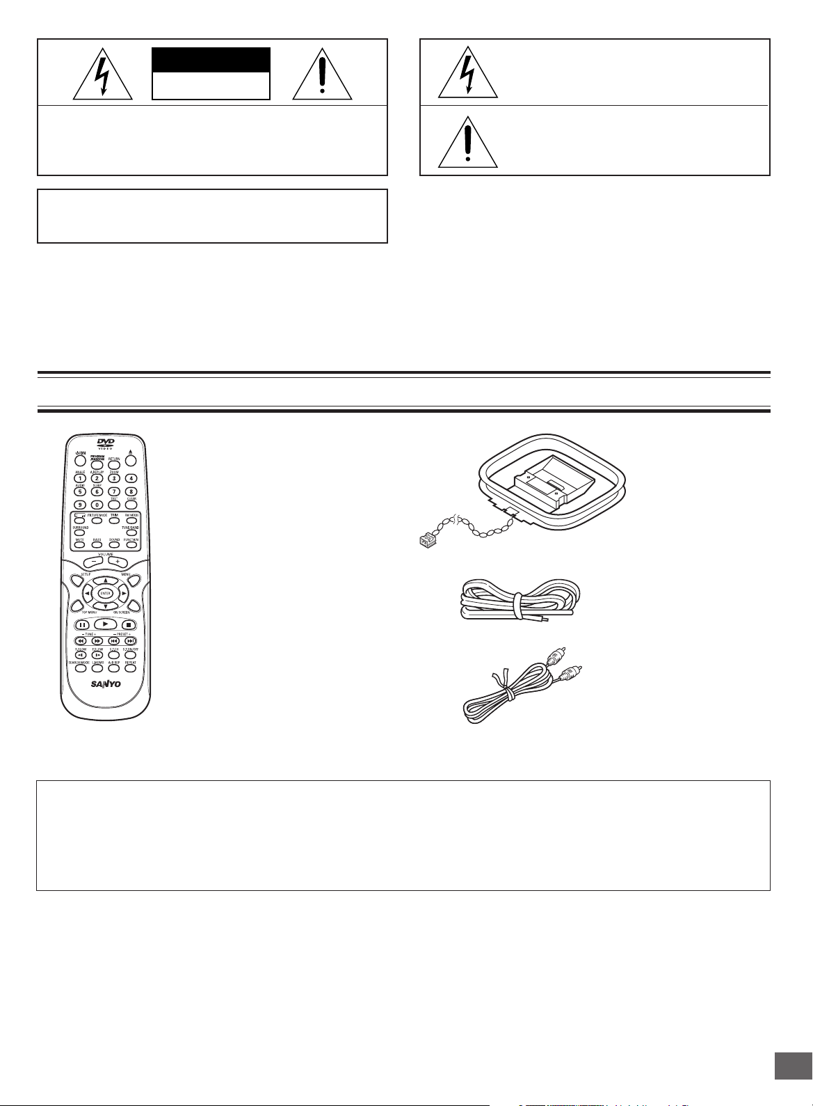
ACCESSORIES
This symbol indicates that there are important operating and maintenance instructions
in the literature accompanying this unit.
WARNING: UNAUTHORIZED RECORDING OF COPY-
RIGHTED MATERIAL MAY VIOLATE APPLICABLE
COPYRIGHT LAWS. THE MANUFACTURER ASSUMES
NO RESPONSIBILITY FOR UNAUTHORIZED DUPLICATION, USE OR OTHER ACTS WHICH INFRINGE UPON
THE RIGHTS OF COPYRIGHT OWNERS.
AM loop antenna
RB-TS780 wireless remote control
FM indoor antenna lead wire
REMOTE CONTROL RB-TS780
Either the main unit or remote control can be operated. However, for convenience, this instruction manual explains
operation using the remote control.
Note:
This handling description is printed prior to product development.
When a part of the product specification must be changed to improve operability or other functions, priority is given to the product
specification itself. In such instances, the instruction manual may not entirely match all the functions of the actual product.
Therefore, the actual product and packaging, as well as the name and illustration, may differ from the manual.
Video cable
-E2-

SAFETY CERTIFICATION
This unit is made and tested to meet exacting safety
standards. It meets UL and FCC requirements and complies with safety performance standards of the U.S. Depart-
ment of Health and Human Services.
CAUTION - USE OF CONTROLS OR ADJUSTMENTS
OR PERFORMANCE OF PROCEDURES OTHER THAN
THOSE SPECIFIED HEREIN MAY RESULT IN HAZARDOUS RADIATION EXPOSURE.
THIS UNIT SHOULD NOT BE ADJUSTED OR REPAIRED
BY ANYONE EXCEPT PROPERLY QUALIFIED SERVICE PERSONNEL.
FCC INFORMATION
This device complies with Part 15 of the FCC Rules.
Operation is subject to the following two conditions:
(1) This device may not cause harmful interference, and (2) this
device must accept any interference received, including
interference that may cause undesired operation.
CAUTION:
Changes or modifications not expressly approved by Sanyo may
void the user's authority to operate this equipment.
Note:
This equipment has been tested and found to comply with the
limits for a Class B digital device, pursuant to Part 15 of the FCC
Rules. These limits are designed to provide reasonable protection
against harmful interference in a residential installation. This
equipment generates, uses and can radiate radio frequency
energy and, if not installed and used in accordance with the
instructions, may cause harmful interference to radio
communications. However, there is no guarantee that interference
will not occur in a particular installation. If this equipment does
cause harmful interference to radio or television reception, which
can be determined by turning the equipment off and on, the user
is encouraged to try to correct the interference by one or more of
the following measures:
• Reorient or relocate the receiving antenna.
•Increase the separation between the equipment and receiver.
• Connect the equipment into an outlet on a circuit different
from that to which the receiver is connected.
• Consult the dealer or an experienced radio/TV technician for
help.
FOR SAFE AND EFFICIENT OPERATION
• Do not damage the power cord.
• When not in use, disconnect the power cord from the outlet.
Grasp the plug, not the cord, when disconnecting the unit.
• If water should enter the unit, electrical shock or a malfunction
may result. Use in an area where there is low humidity and
little dust.
• Do not disassemble or alter the unit in any way.
• Do not use the unit in areas where extremes in temperature
occur (below 40°F (5°C) or exceeding 95°F (35°C)), or where
it may be exposed to direct sunlight.
• Because of the DVD video player’s extremely low noise and
wide dynamic range, there is a tendency to set the volume on
the amplifier higher than necessary. Doing so may produce
an excessively high output from the amplifier which can
cause damage to your speakers. Please be careful in this
regard.
• Sudden changes in the surrounding temperature can cause
dew to form on the optical pickup lens inside the unit. Under
this condition the unit may be unable to operate properly. If
this should occur, remove the disc and allow the unit to adjust
to the surrounding temperature.
• Do not pull the disc out while the disc is retracting into the
loading slot.
• Never put anything except a 5-inch (12cm) or 3-inch (8cm)
DVD (or CD) into the loading slot.
Foreign objects can damage the unit.
• Always push the disc gently into the loading slot until automatic
loading begins, then release the disc. Do not apply pressure
to the disc after automatic loading begins.
• When carrying the unit, be sure to remove a disc which
may be inside and turn the power off. Then unplug the
power cord from the AC outlet after 10 seconds. Carrying
the unit with a disc inside may damage the disc and/or
the unit.
• The unit is automatically set to the Screen Saver mode
after approximately 5 minutes have elapsed under the
stop or pause mode.
• After you press the q button on the unit to eject the disc, you
must remove the disc from the loading slot. If you do not
remove the disc within approximately 2 minutes, the disc is
automatically retracted into the loading slot. Some DVD video
discs may start playback automatically.
CAUTION:
The unit must be placed in a well ventilated area.
Do not place any object on the top of the unit.
Do not block ventilation holes.
The cabinet of the unit warms up when it is used for a long time,
but it is not a malfunction.
Adjusting the FL display brightness
While holding [n] down on the unit, press [ON SCREEN]
repeatedly on the remote control. The display changes as
shown below.
DARK v NORMAL v DARK ...
-E3-
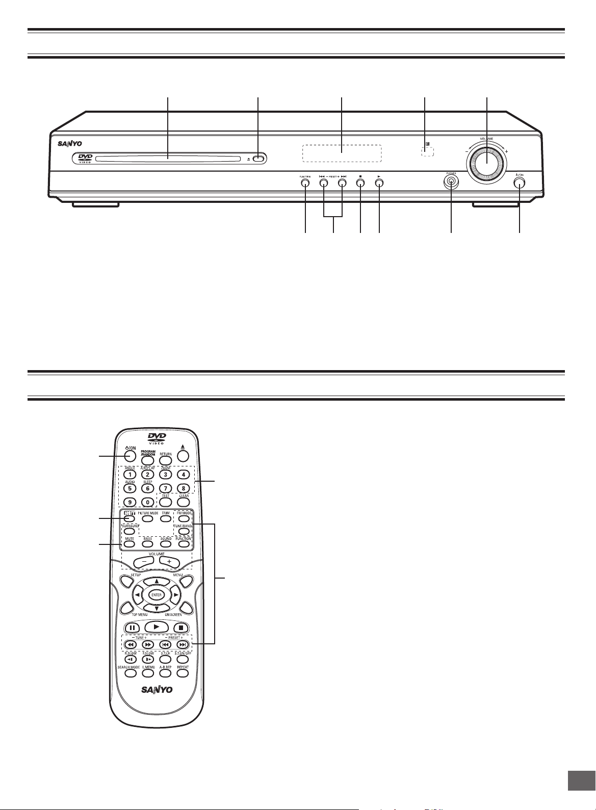
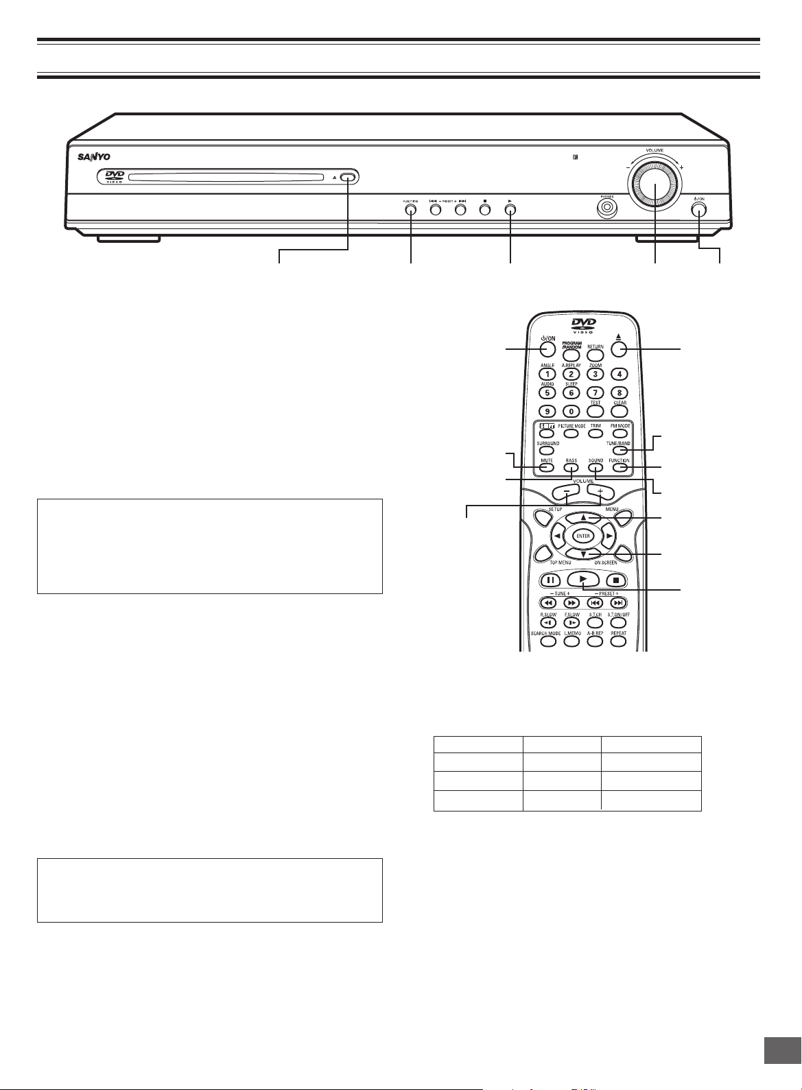
CONTROLS
2 3 451
7 6891011
1. Loading slot
2. Eject button (q)
3. FL display
4. Remote sensor (IR)
5. Volume control (VOLUME)
6. Power button (z/ON)
1
5
4
REMOTE CONTROL RB-TS780
7. Headphone jack (PHONES)
8. Play button (a)
9. Stop button (n)
10. Preset tuning, Skip/Next/Previous buttons
(f - PRESET + e)
11. Function button (FUNCTION)
REMOTE CONTROL
1. Power button (z/ON)
2. Number and other function buttons
These buttons are used as number buttons and as function
buttons of each name.
• When using as a number button, press the appropriate
2
3
button directly.
• When using as a function button of each name, press the
appropriate button while holding the SHIFT button down.
Number buttons (1 – 9, 0)
Angle button (ANGLE)
Angle replay button (A.REPLAY)
Zoom button (ZOOM)
Audio button (AUDIO)
Sleep button (SLEEP)
3. Tuner controls
FM mode button (FM MODE)
Tuner function/Band select button (TUNE/BAND)
Tuning buttons (- TUNE +)
Preset tuning buttons (- PRESET +)
4. Amplifier controls
Surround button (SURROUND)
Muting button (MUTE)
Bass button (BASS)
Sound preset button (SOUND)
Function button (FUNCTION)
Volume buttons (- VOLUME +)
5. Shift button (SHIFT)
-E4-
28
26
24
22
31
29
27
25
23
21
REMOTE CONTROL RB-TS780
6
8
1030
12
14
16
18
20
7
9
11
13
15
17
19
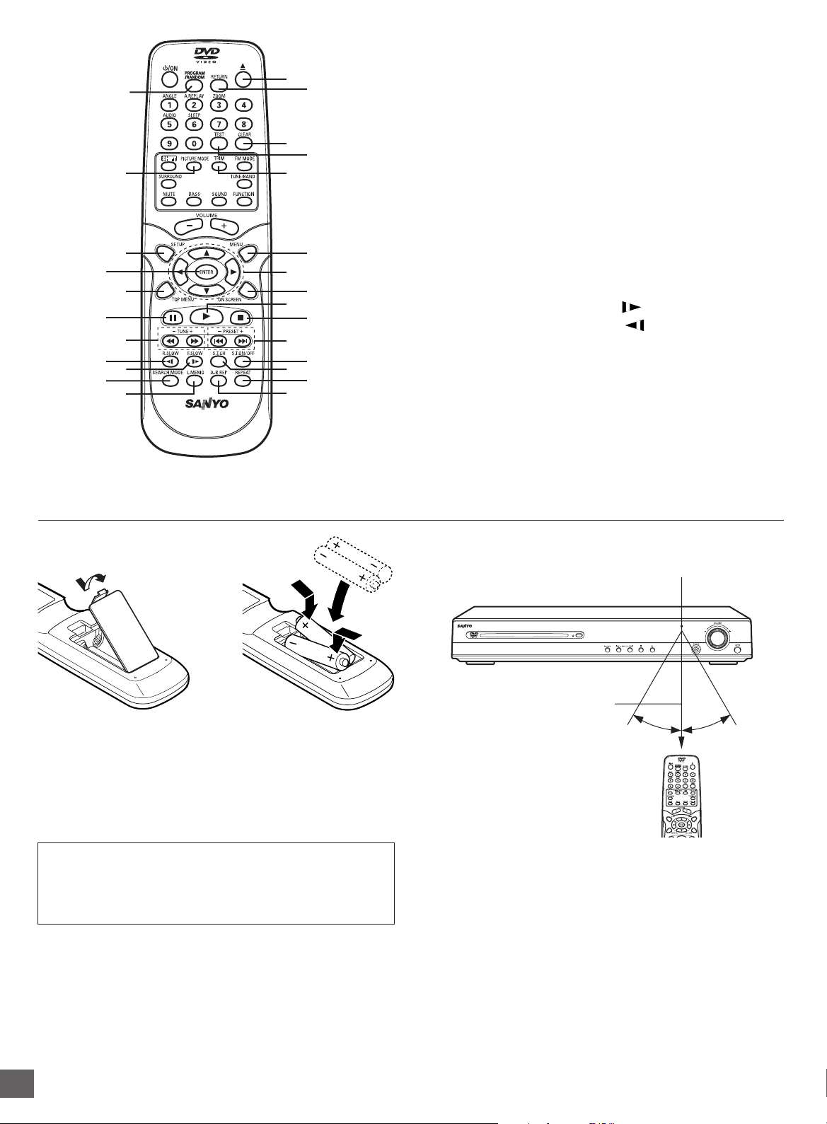
6. Eject button (q)
7. Return button (RETURN) (See page E30.)
8. Clear button (CLEAR)
9. Test tone button (TEST) (See page E14.)
10. Trim button (TRIM)
11. Menu button (MENU)
12. Directional arrow buttons (o, a, p, b)
13. On-screen display button (ON SCREEN)
14. Play button (a)
15. Stop button (n)
16. Skip/Next/Previous buttons (f, e)
17. Subtitle On/Off button (S.T.ON/OFF)
18. Subtitle change button (S.T.CH)
19. Repeat button (REPEAT)
20. A-B repeat button (A-B REP)
21. Last memory button (L.MEMO)
22. Search mode button (SEARCH MODE)
23. Forward slow button (F.SLOW )
24. Reverse slow button (R.SLOW )
25. Fast forward/Fast reverse buttons (d, c)
26. Pause/Step button (k)
27. Top menu button (TOP MENU)
28. Enter button (ENTER)
29. Setup button (SETUP)
30. Picture mode button (PICTURE MODE)
31. Program/Random play button (PROGRAM/RANDOM)
Inserting batteries
12
Two "AA" batteries
(not supplied)
Note:
Remove the batteries if the remote control is not to be used for a
month or more. Batteries left in the unit may leak and cause
damage.
IMPORTANT NOTE:
SPENT OR DISCHARGED BATTERIES MUST BE
RECYCLED OR DISPOSED OF PROPERLY IN COMPLIANCE
WITH ALL APPLICABLE LAWS.
FOR DETAILED INFORMATION, CONTACT YOUR LOCAL
COUNTY SOLID WASTE AUTHORITY.
Remote control range
Remote sensor
Within approx. 20 feet
(6 meters)
Note:
This is not Multi-brand Remote Control.
It cannot operate your TV and VCR.
30°30°
-E5-
BASIC CONNECTIONS
Note:
Do not connect the power cord to a 120VAC 60Hz outlet until
all connections have been made.
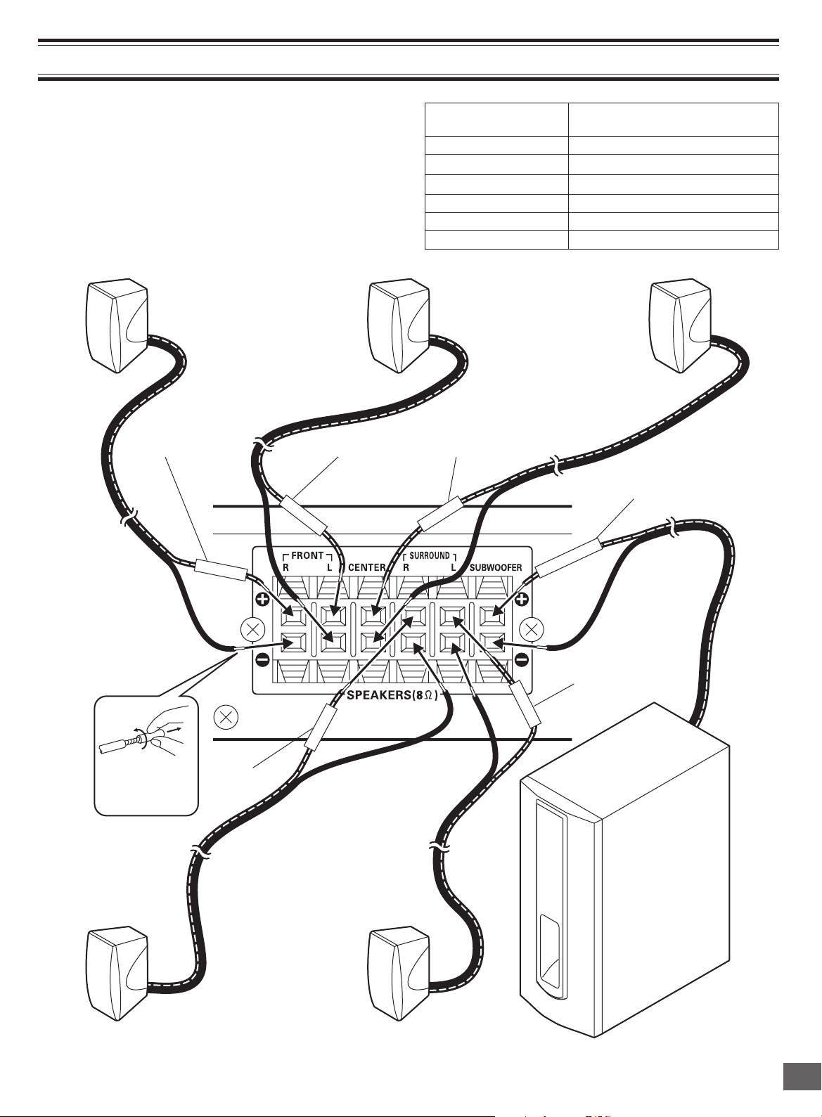
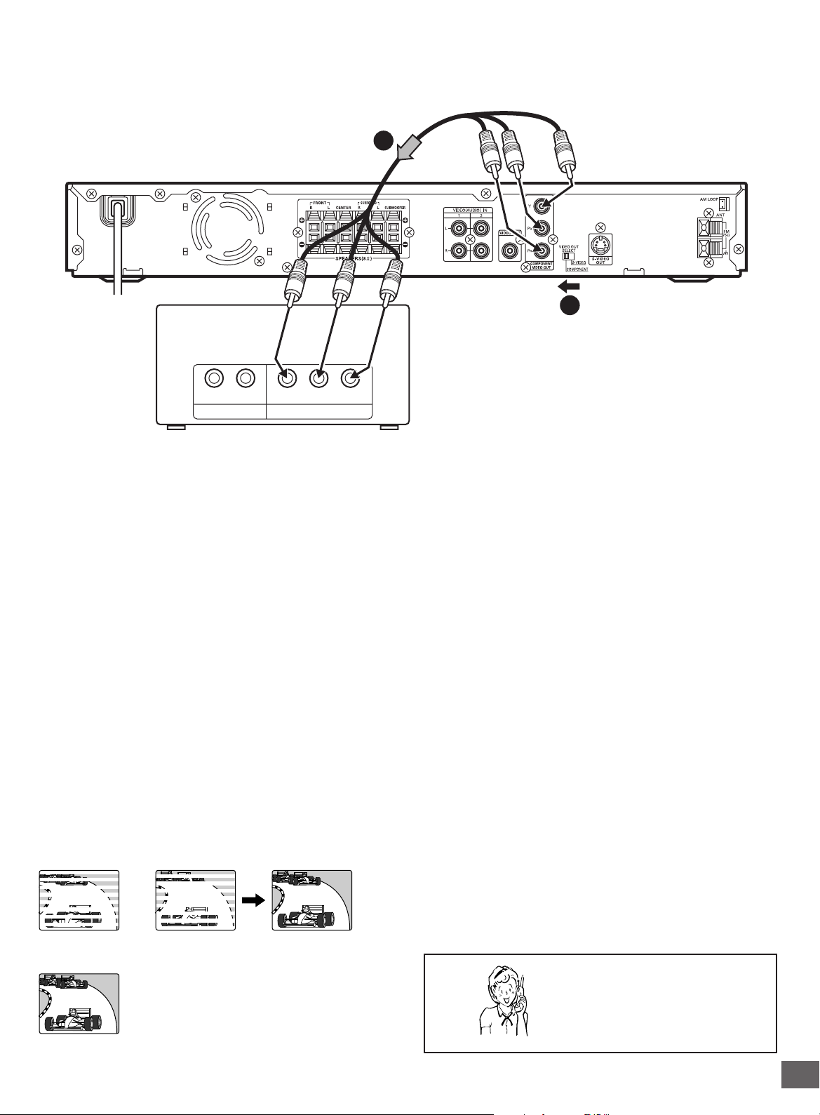
Speaker Connections
To achieve proper stereo reproduction, connect the speaker
wires without shorting to adjacent wires as shown below.
Front right speaker Front left speaker Center speaker
Red White
FRONT L
Tube of Speaker Wire Use
(Positive Polarity)
FRONT R (Red) Front right speaker
FRONT L (White) Front left speaker
CENTER (Green) Center speaker
REAR R (Gray) Surround right speaker
REAR L (Blue) Surround left speaker
SUBWOOFER (Violet) Subwoofer
Green
Violet
Twist and pull it
off.
F
RONT R
Gray
REAR R
CENTER
SUBWOOFER
REAR L
Blue
Surround right speaker
Surround left speaker
-E6-
Subwoofer
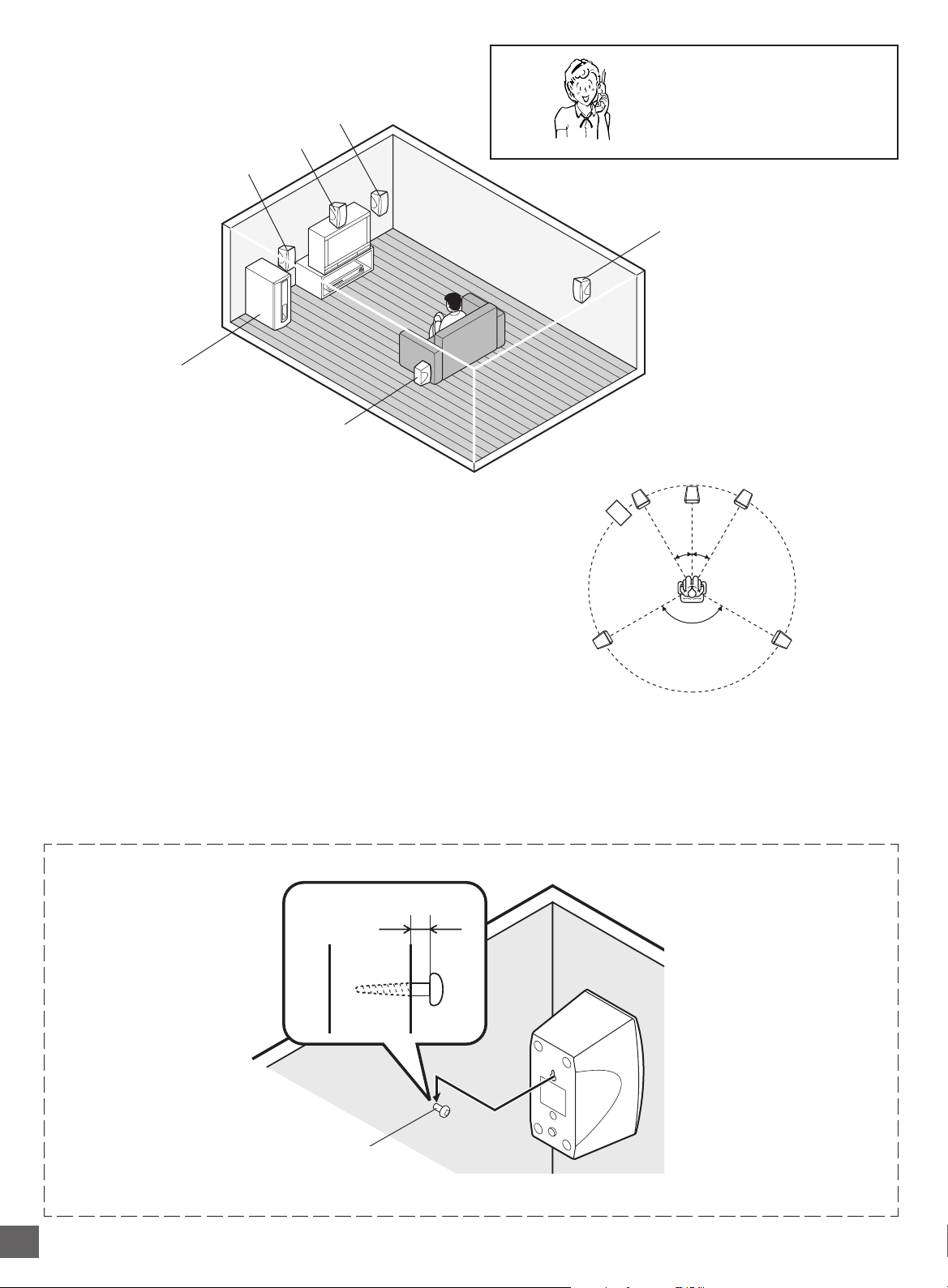
Speaker Placement
Front left speaker
Subwoofer
Place it near the front speaker.
Front right speaker
Center speaker
Surround left speaker
Need help? Call
1-800-813-3435
Surround right speaker
The center speaker and front right/left speakers have build-in
magnetic stray field compensation. They may be placed close to
a TV without affecting the color purity.
Place the front left/right speakers either side of the TV.
Place the center speaker directly above the TV.
• The front, center, and surround speakers should be placed at
approximately the same distance from the listening position.
The surround right/left speakers and subwoofer do not have
build-in magnetic stray field compensation.
Keep enough distance between the subwoofer and the TV so as
not to garble the TV screen.
Place the surround speakers either sides of the listening position,
or slightly to the rear, approximately 2 feet ~ 3 feet 3 inches (60
cm ~ 1 meter) higher than ear level.
Example: To hang the speaker on a wall
Approximately 1/8 inch
(3 mm)
Front left speaker Front right speaker
Subwoofer
Surround left
speaker
Notes:
• The angles in the diagram are approximate.
• Please refer to “Setting Audio” on page E34.
• Set the TV’s built-in speaker volume to minimum.
Center speaker
30°30°
120°
Surround right
speaker
Round head screw
(not supplied)
Note: Be careful of dropping the speaker system, it might cause damage or serious injuries.
-E7-
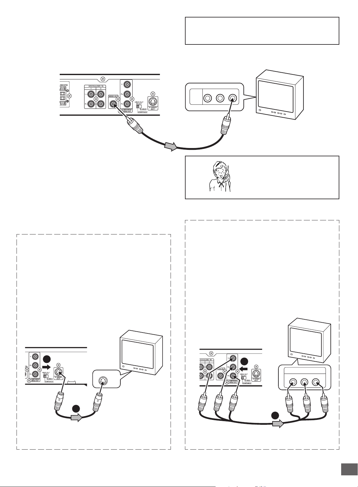
Conventional TV Connection
Using VIDEO OUT jack
Connect the Video cable with yellow connectors (supplied)
between the VIDEO OUT jack of the unit and the VIDEO INPUT
jack on the TV.
Important Information:
To connect the unit to a TV, TV must have a Video input jack
(RCA-type) at least. You cannot connect it to an antenna
terminal of TV.
Partial back panel
To VIDEO OUT jack (Yellow)
Video cable (supplied)
Notes:
• Please refer to your TV instruction manual.
• When you connect the unit to your TV, be sure to turn off the
power and disconnect both units from the wall outlet until all
the connections have been made.
• Do not connect the VIDEO OUT, S-VIDEO OUT, and
COMPONENT VIDEO OUT jacks of the unit to a VCR directly.
The playback picture will be distorted because DVD video
discs are copy protected.
Using S-VIDEO OUT jack
Note:
Please follow the steps before turn on the power.
1. If your TV has the S-VIDEO INPUT jack, connect the *Svideo cable (not supplied) between the S-VIDEO OUT jack
of the unit and the S-VIDEO INPUT jack of the TV. (The
VIDEO OUT jack connection is not necessary.)
You can enjoy clearer picture playback.
TV
To VIDEO INPUT jack
AUDIO
R-AUDIO-L VIDEO
VIDEO
INPUT
1
Need help? Call
1-800-813-3435
Using COMPONENT VIDEO OUT jacks
Note:
Please follow the steps before turn on the power.
1. If your TV has the COMPONENT VIDEO INPUT jacks,
connect the *Component video cable (not supplied) between
the COMPONENT VIDEO OUT jacks of the unit and the
COMPONENT VIDEO INPUT jacks of the TV.
(The VIDEO OUT or S-VIDEO OUT jack connection is not
necessary.)
You can enjoy high quality picture playback.
2. Set the VIDEO OUT SELECT switch to the S-VIDEO position.
TV with S-VIDEO INPUT jack
Partial back panel
2
S-VIDEO IN 1
1
*S-video cable (not supplied)
*Please consult your local audio/video dealer.
2. Set the VIDEO OUT SELECT switch to the COMPONENT
position.
TV with COMPONENT
VIDEO INPUT jacks
Partial back panel
2
COMPONENT VIDEO INPUT
YPBP
Green
Green
Blue
Red
1
*Component Video cable (not supplied)
*Please consult your local audio/video dealer.
-E8-
R
RedBlue
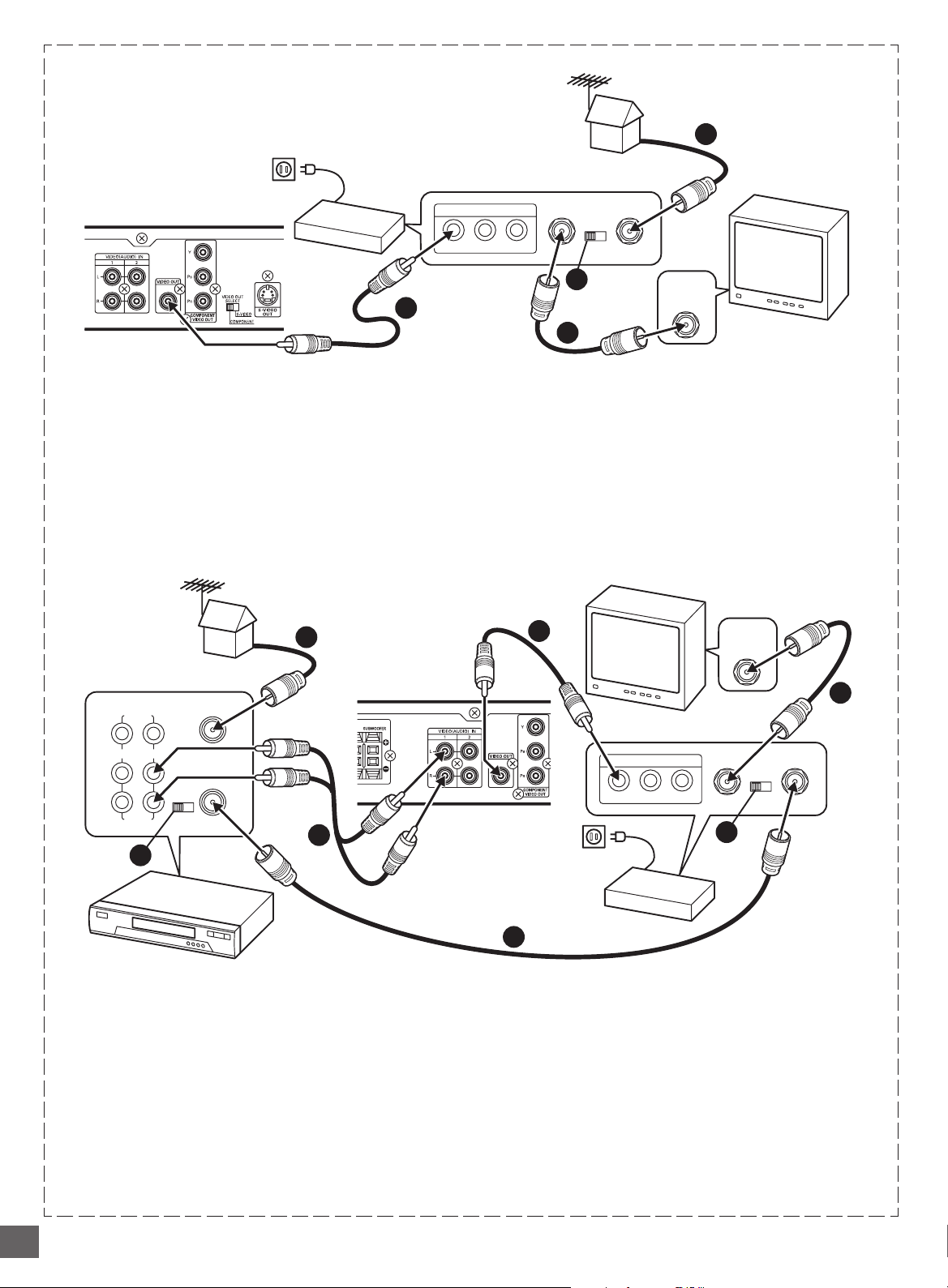
Using RF Modulator
If your TV does not have a Video input jack and has an antenna
terminal only, please purchase the *RF Modulator (not supplied).
(*Please consult your audio/video dealer.)
Example: Unit, TV and RF Modulator connections
Partial back panel
3
To VIDEO OUT jack (Yellow)
1. Connect the antenna cable (not supplied) to the ANT. IN
terminal of the RF Modulator.
2. Connect the 75-ohm coaxial cable (not supplied) between
the TO TV terminal of the RF Modulator and the VHF/UHF
ANTENNA IN terminal of the TV.
3. Connect the Video cable with yellow connectors (supplied)
between the VIDEO OUT jack of the unit and the VIDEO
input jack of the RF Modulator.
Example: Unit, VCR, TV and RF Modulator connections
To VIDEO OUT jack (Yellow)
1
RF Modulator
A/V INPUT JACKS
R-AUDIO-LVIDEO
TO TV
CHANNEL
34
4
ANT. IN
VHF/UHF
ANTENNA
IN
TV
2
4. Turn on the TV, and set the channel number (CHANNEL3 or
CHANNEL4) on both TV and RF Modulator, whichever is not
used for regular broadcasts in your area.
Note:
For more details, please refer to the instruction manual of the RF
Modulator.
TV
1
VHF/UHF
L
34
R
CHANNEL
FROM ANT.
IN
TO TV
OUT
VIDEO
LINE1(AUX1)
IN OUT
L
R
AUDIO
4
6
HiFi Stereo VCR
1. Connect the antenna cable (not supplied) to the VHF/UHF
FROM ANT IN terminal of the VCR.
2. Connect the 75-ohm coaxial cable (not supplied) between
the TO TV OUT terminal of the VCR and the ANT. IN
terminal of the RF Modulator.
3. Connect the 75-ohm coaxial cable (not supplied) between
the TO TV terminal of the RF Modulator and the VHF/UHF
ANTENNA IN terminal of the TV.
4. Connect the audio cables (not supplied) between the VIDEO
(AUDIO) IN 1 or 2 jacks of the unit and the AUDIO OUT jacks
of the VCR. Use the red connectors for the right-R jacks and
the white connectors for the left-L jacks.
TO TV
VHF/UHF
ANTENNA
IN
CHANNEL
34
ANT. IN
5
A/V INPUT JACKS
R-AUDIO-LVIDEO
Partial back panel
6
2
RF Modulator
5. Connect the Video cable with yellow connectors (supplied)
between the VIDEO OUT jack of the unit and the VIDEO
input jack of the RF Modulator.
6. Turn on the TV, and set the channel number (CHANNEL3 or
CHANNEL4) on all TV, VCR and RF Modulator, whichever is
not used for regular broadcasts in your area.
Note:
For more details, please refer to the instruction manual of the RF
Modulator.
3
-E9-
Progressive-scan TV Connection
Your TV must be capable of handling progressive scanning and have component video input capability.
*Component video cable (not supplied)
1
To AC 120V, 60Hz
Green
COMPONENT VIDEO INPUTAUDIO INPUT
TV with progressive-scan capability
1. Connect to the component video input jacks. (The VIDEO
OUT or S-VIDEO OUT jack connection is not necessary.)
2. Set the VIDEO OUT SELECT switch to the COMPONENT
position.
3. Set the unit to the PROGRESSIVE position. See page
E16.
Blue
BRL PR
YP
Red
Blue
Green
2
Red
*Please consult your local audio/video dealer.
Notes:
• Please refer to your TV instruction manual.
• When you connect the unit to your TV, be sure to turn off the
power and disconnect both units from the wall outlet until all
the connections have been made.
• Do not connect the unit to a VCR directly. The playback
picture will be distorted because DVD video discs are copy
protected.
Progressive Scanning
While interlaced scanning produces one frame of video in two
fields, progressive scanning creates one frame in one field.
Conventional interlaced scanning constitutes one second with
30 frames (60 fields), but progressive scanning constitutes it with
60 frames from scratch. Progressive scanning can reproduce
sharper picture with high resolution for still image or other picture
containing long texts or horizontal lines.
This model has compliance with 525p (progressive) system.
Interlaced scanning
+
Progressive scanning
Need help? Call
1-800-813-3435
-E10-
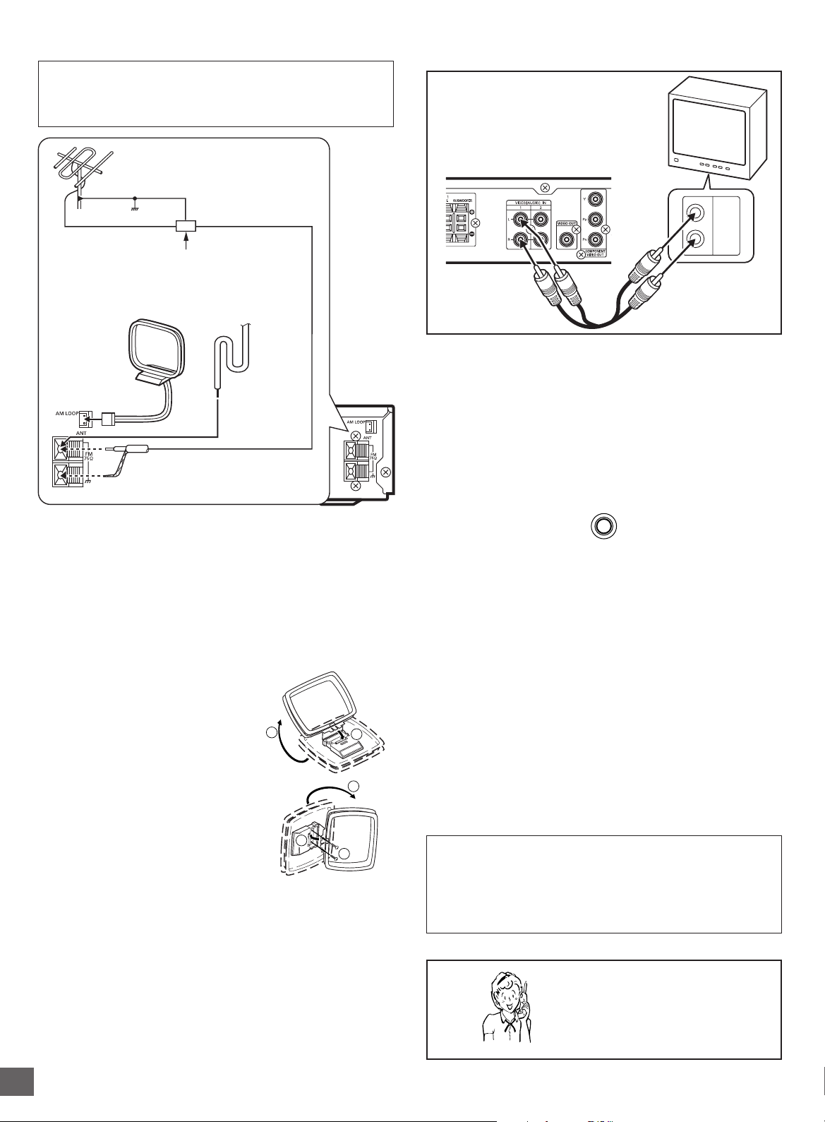
Antenna Connections
CAUTION:
When installing an outdoor antenna, follow the installation
instructions in the attached “IMPORTANT SAFETY
INSTRUCTIONS”.
FM outdoor antenna
(not supplied)
Additional Connection Examples
To enjoy your TV sounds
If your TV has the audio output jacks,
connect an audio cable (not supplied) from
the audio output jacks of the TV to the
VIDEO (AUDIO) IN 1 jacks.
TV
Ground
Antenna discharge unit (not supplied)
AM loop antenna
FM indoor antenna
lead wire
Plug
75-ohm coaxial cable
(not supplied)
FM antenna
The FM indoor antenna lead wire is sufficient to receive most
local FM broadcasts and should be connected to the rear FM
75Ω terminal. Extend the antenna lead wire as straight as possible
and, while listening to the sound from the system, secure it in a
position where the best FM reception is found.
In fringe areas, or where reception is distorted or noisy, an FM
outdoor antenna (not supplied) should be connected instead of
the FM indoor antenna lead wire. The terminals will accept 75ohm coaxial cable.
AM antenna
The AM loop antenna is sufficient to
receive most local AM broadcasts.
Assemble the loop antenna.
1
2
L
AUDIO
OUTPUT
R
Audio cable
(not supplied)
2nd video equipment input jack (VIDEO (AUDIO) IN 2)
Connect an audio cable (not supplied) from the audio output
jacks of the video equipment to the VIDEO (AUDIO) IN 2 jacks.
Headphones jack (PHONES)
Connect a pair of stereo headphones with miniplug (8 ohms - 32
ohms, not available from SANYO) to the PHONES jack for
monitoring or for private listening. The speakers are automatically
disconnected when headphones are connected.
PHONES
Power Supply
Connect the power cord to a 120VAC 60Hz outlet. This unit is
equipped with a polarized plug. If you have difficulty inserting the
plug, turn it over and reinsert it. If the unit will not be used for a
long time, disconnect the AC plug from the AC outlet.
Notes:
• Before plugging the power cord into an AC outlet, make sure
that all the connections have been made.
• The unit is not disconnected from the AC power unless the
power cord is unplugged from the AC outlet.
Unwind the antenna wires, then
connect the plug to the AM LOOP
1
terminal. If you have difficulty inserting
the plug, turn it over and reinsert it.
Place the loop antenna in a position
which yields the best AM reception, or
3
2
attach it to a wall or other surface as
shown.
Screws (not supplied)
Note:
To minimize noise...
• Keep the speaker wires, power cord and all other system
connection cables away from the loop antenna.
• Do not place the antenna close to a TV or speaker.
Note to CATV system installer:
This reminder is provided to call the CATV system installer’s
attention to Section 820-40 of the NEC which provides guidelines
for proper grounding and, in particular, specifies that the cable
ground shall be connected to the grounding system of the
building, as close to the point of cable entry as practical.
Need help? Call
1-800-813-3435
-E11-
MUTE
BASS
TUNE/BAND
FUNCTION
SOUND
z/ON
a
(Play)
q
(Eject)
– VOLUME +
4
5
Common Operation
BEFORE OPERATION
(Eject)
Turning the power on and off
Press [z/ON] to turn the power on.
• “HELLO” appears briefly on the FL display.
(After connecting the power cord, when you press [z/ON] for the
first time, the volume-reset feature automatically sets the initial
volume level.)
When the power cord is connected to the AC outlet, the unit will
respond to commands from the remote control.
To turn the power off, press [z/ON] again.
• “GOOD-BYE” appears briefly on the FL display.
Smart start function
If the following buttons are pressed when the power is turned
off, the unit turns on automatically and the selected source is
activated.
[q], [a] (Front panel of the unit)
[q], [a], [TUNE/BAND] (Remote control)
Selecting the source
Press [FUNCTION] to select the desired source. Each time the
button is pressed, the display changes as follows:
DVD/CD
VIDEO 1
VIDEO 2
FM TUNER
AM TUNER
• When the source selection is changed, disc playback
automatically stops.
Adjusting the volume
Rotate [VOLUME] (or press [VOLUME] + or - on the remote
control). The volume level appears on the FL display (VOLUME
0 ~ VOLUME MAX).
To reduce the volume temporarily (muting)
Press [MUTE] on the remote control. “MUTE” blinks on the FL
display.
To restore the previous volume setting, press [MUTE] again.
FUNCTION VOLUME
a
(Play)
Selecting the sound mode
1. Press [SOUND] repeatedly to select the desired sound mode
(“BASS”, “TREBLE” or “NIGHT”).
2. Press the button as desired.
Sound mode Press Display change
BASS p or o “-5” ~ “+5”
TREBLE p or o “-5” ~ “+5”
NIGHT ENTER “ON” or “OFF”
Note for “NIGHT”:
When enjoying a DVD disc with the volume set low at night,
select this mode. It enhances spoken lines making speech
clearer.
3. Repeat steps 1 to 2 for another sound mode.
4. Press [SOUND] repeatedly to close the display.
Bass boost system
Press [BASS] repeatedly to select the desired bass boost effect.
BASS BOOST v BASS OFF v NORMAL v BASS
BOOST . . .
z/ONq
-E12-
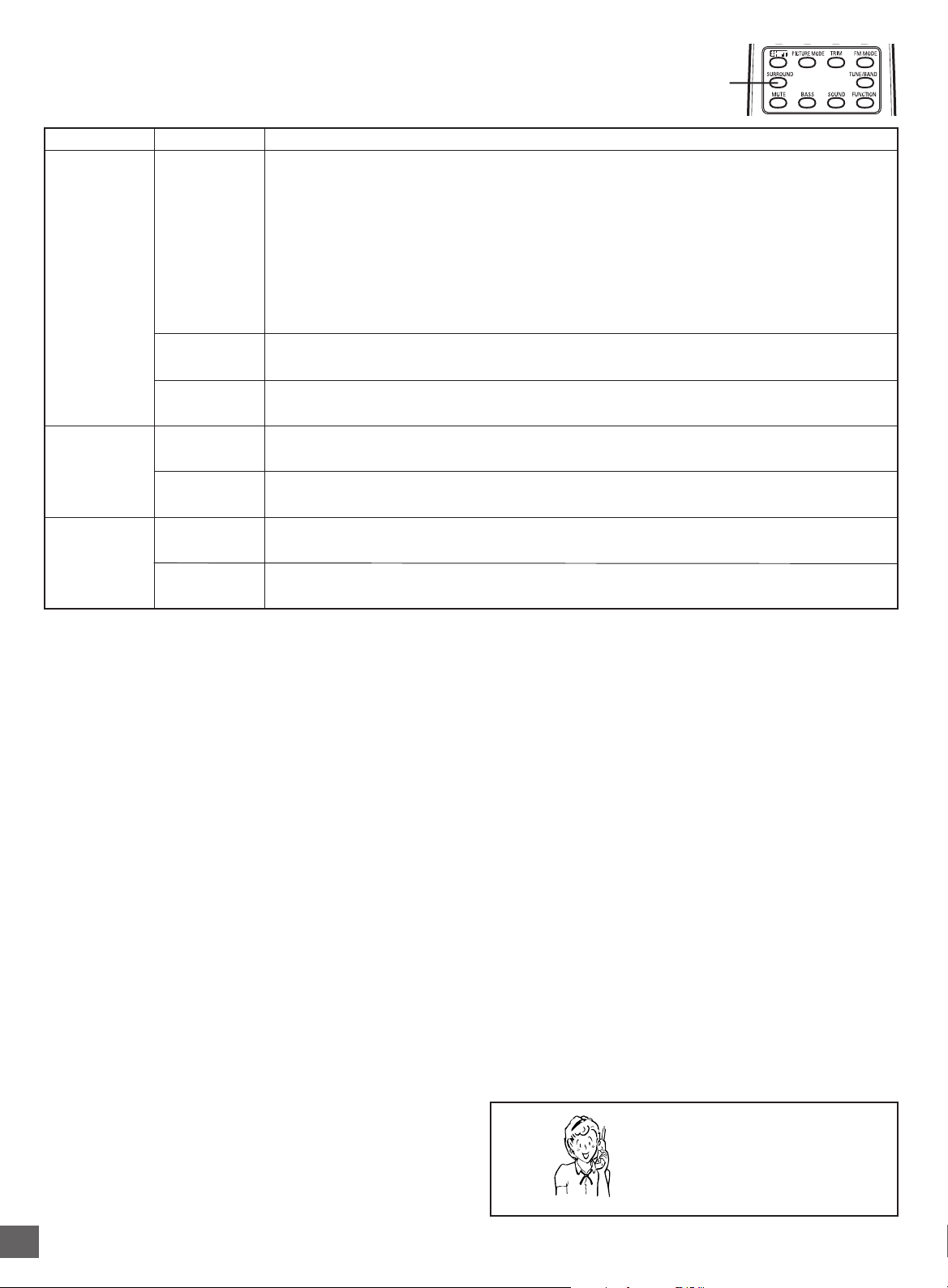
SURROUND
Selecting Surround Mode
Press [SURROUND] to select the surround mode.
Each time the button is pressed, the surround mode changes as follows:
AUTO SURR v 5.1ch SURR v 2.1ch ST v AUTO SURR…
Function Description
VIDEO 1
VIDEO 2
FM TUNER
(Stereo)
FM TUNER
(Mono)
AM TUNER
FL display
AUTO SURRDVD/CD
5.1ch SURR
2.1ch ST
AUTO SURR
5.1ch SURR
2.1ch ST
AUTO SURR
5.1ch SURR
2.1ch ST
The unit selects the surround mode automatically depending on the disc.
• If a DVD disc is encoded with Dolby Digital 5.1 channel, it is played back with Dolby Digital 5.1
channel surround sound.
Not all DVD discs are encoded with Dolby Digital 5.1 channel surround sound.
• If a DVD disc is encoded with Dolby Digital 2 channel or mono, it is played back with Dolby Pro
Logic mode. “DOLBY PL” appears briefly on the FL display.
• If a DVD disc is encoded with 2 channel Linear PCM (stereo), it is played back with Dolby Pro
Logic mode. “DOLBY PL” appears briefly on the FL display.
• Audio CDs are played back with Dolby Pro Logic mode.
• MP3 discs are played back with Virtual 5.1 channel surround sound.
Disc is played back with Virtual 5.1 channel surround sound.
The surround mode is set to 2.1 channel (Front left and right speakers, and Subwoofer).
The surround mode is set to Virtual 5.1 channel surround sound.
The surround mode is set to 2.1 channel (Front left and right speakers, and Subwoofer).
Front left and right speakers, Center speaker, and Subwoofer sound.
The surround mode is set to 2.1 channel (Front left and right speakers, and Subwoofer).
Notes:
• When using headphones, the surround mode does not change. If [BASS] or [SURROUND] is pressed, “-BASS-” or “-SURR-”
appears briefly on the FL display.
• DVD video discs with DTS may not work correctly. You can see the picture on the TV screen, but there is no sound.
In this case, press the AUDIO button repeatedly while holding the SHIFT button down to select Dolby Digital sound. (See page E25.)
• When receiving weak FM broadcasts, set the mode to “2.1ch ST”. The sound quality may improve.
Manufactured under license from Dolby Laboratories.
“Dolby”, “Pro Logic” and the double-D symbol are trademarks of Dolby Laboratories.
Need help? Call
1-800-813-3435
-E13-
 Loading...