


Digital Video Recorder
Manual for Remote Operations using
a Network Connection
DSR-3716PA
DSR-3709PA
DSR-3706PA

Table of Contents
Introduction . . . . . . . . . . . . . . . . . . . . . . . . . . . . . . . . . . . 2
b Features of Network Operation. . . . . . . . . . . . . . . . . 2
b Operating Environment. . . . . . . . . . . . . . . . . . . . . . . 2
Network Connection Procedure . . . . . . . . . . . . . . . . . . . 3
1 NETWORK SET Settings of DVR. . . . . . . . . . . . . . . 3
2 TCP/IP Settings of the Computer . . . . . . . . . . . . . . . 3
3 Network Operation Screen Display. . . . . . . . . . . . . . 5
b Network Connection Restrictions . . . . . . . . . . . . . . . 6
b Change to DVR Operation . . . . . . . . . . . . . . . . . . . . 6
Organization of the Main Screen
and Functions of Each Part . . . . . . . . . . . . . . . . . . . . . . 7
b Organization of Main Screen . . . . . . . . . . . . . . . . . . 7
1 Functions of Operation Panel
and Operation Authority . . . . . . . . . . . . . . . . . . . . . . 8
2 Operating mode display panel . . . . . . . . . . . . . . . . . 9
View Live Video . . . . . . . . . . . . . . . . . . . . . . . . . . . . . . . 10
1 Change display pattern of live video. . . . . . . . . . . . 10
2 Set the display mode for images . . . . . . . . . . . . . . 11
3 Playback audio . . . . . . . . . . . . . . . . . . . . . . . . . . . . 11
Recording Monitored Images . . . . . . . . . . . . . . . . . . . . 12
b Normal Recording (Normal Recording Area) . . . . . 12
b Other Recording Methods. . . . . . . . . . . . . . . . . . . . 12
View Recorded Images . . . . . . . . . . . . . . . . . . . . . . . . . 13
b Playback Recorded Images . . . . . . . . . . . . . . . . . . 13
b Basic Playback Operations. . . . . . . . . . . . . . . . . . . 13
Search Recorded Images . . . . . . . . . . . . . . . . . . . . . . . 14
b Search Screen Selection . . . . . . . . . . . . . . . . . . . . 14
1 ALARM SEARCH . . . . . . . . . . . . . . . . . . . . . . . . . . 14
2 ALARM THUMBNAIL SEARCH . . . . . . . . . . . . . . . 14
3 TIME/DATE SEARCH . . . . . . . . . . . . . . . . . . . . . . . 15
4 ARCHIVE AREA SEARCH. . . . . . . . . . . . . . . . . . . 15
5 MOTION DETECTION SEARCH . . . . . . . . . . . . . . 16
Saving Images . . . . . . . . . . . . . . . . . . . . . . . . . . . . . . . . 17
A Saving live video on the computer . . . . . . . . . . . . . 17
B Copying Recorded Images
to the DVR’s Archive Area . . . . . . . . . . . . . . . . . . . 18
C Downloading Recorded Images
to the Computer . . . . . . . . . . . . . . . . . . . . . . . . . . . 19
D Saving Format for Image Files . . . . . . . . . . . . . . . . 20
Setting up the Basic Menu
Using Network Operations . . . . . . . . . . . . . . . . . . . . . . 22
Basic Settings Menu Outline . . . . . . . . . . . . . . . . . . . . 22
Basic menu setting procedure . . . . . . . . . . . . . . . . . . 23
Initial setting. . . . . . . . . . . . . . . . . . . . . . . . . . . . . . . . . . 24
A CLOCK SET . . . . . . . . . . . . . . . . . . . . . . . . . . . . . . 24
B SUMMER TIME SET/EXT. CLOCK SET. . . . . . . . . 24
C HOLIDAY SET. . . . . . . . . . . . . . . . . . . . . . . . . . . . . 24
Recording settings . . . . . . . . . . . . . . . . . . . . . . . . . . . . 25
A ARECORDING AREA SET. . . . . . . . . . . . . . . . . . . 25
B RECORDING CONDITIONS SET . . . . . . . . . . . . . 26
C NORMAL REC MODE SET . . . . . . . . . . . . . . . . . . 27
D PROGRAM REC SET . . . . . . . . . . . . . . . . . . . . . . . 28
E TIMER SET. . . . . . . . . . . . . . . . . . . . . . . . . . . . . . . 28
F ALARM REC MODE SET . . . . . . . . . . . . . . . . . . . . 30
General settings. . . . . . . . . . . . . . . . . . . . . . . . . . . . . . . 32
A DISPLAY SET . . . . . . . . . . . . . . . . . . . . . . . . . . . . . 32
B BUZZER SET . . . . . . . . . . . . . . . . . . . . . . . . . . . . . 32
C HDD SET . . . . . . . . . . . . . . . . . . . . . . . . . . . . . . . . 33
D NETWORK SET . . . . . . . . . . . . . . . . . . . . . . . . . . . 34
E RS-485 SET . . . . . . . . . . . . . . . . . . . . . . . . . . . . . . 34
Screen settings and DVR information . . . . . . . . . . . . . 35
A MASK SET . . . . . . . . . . . . . . . . . . . . . . . . . . . . . . . 35
B POWER LOSS/USED TIME . . . . . . . . . . . . . . . . . . 35
C INTIALIZATION LOG . . . . . . . . . . . . . . . . . . . . . . . 35
DVR Viewer2. . . . . . . . . . . . . . . . . . . . . . . . . . . . . . . . . . 36
b Operating Environment . . . . . . . . . . . . . . . . . . . . . . 36
b Installing the Viewer Software. . . . . . . . . . . . . . . . . 36
b Internet Option Settings . . . . . . . . . . . . . . . . . . . . . 36
b Running and Quitting Viewer . . . . . . . . . . . . . . . . . 36
b Structure of the Screen and the
Function of each Section . . . . . . . . . . . . . . . . . . . . 37
b Opening Iimage Files . . . . . . . . . . . . . . . . . . . . . . . 38
b Switching the Display Pattern of the Screen . . . . . . 39
b Selecting the Channel Displayed on the Screen. . . 39
b Functions of the Viewer Operating Panel . . . . . . . . 40
b Saving and Printing Images . . . . . . . . . . . . . . . . . . 41
b Setting the Date and Time Display Format . . . . . . . 41
Operating a Dome Camera . . . . . . . . . . . . . . . . . . . . . 21
English 1
Introduction
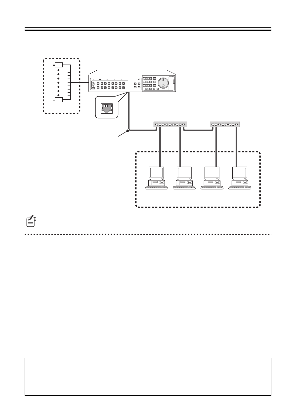
Connect the computer and digital video recorder (DVR) using a LAN. The DVR can be operated from the computer through
the network.
1
16
Camera
Digital Video Recorder (DVR)
LAN
Switching hub Switching hub
LAN cable
10BASE-T/100BASE-TX
(category 5 straight cable)
1 2 3 4
PC/AT compatible machine
The type of LAN cable differs depending on the connection method.
Refer to the instruction manual of the DVR for details.
bFeatures of Network Operation
• It allows to remotely control the settings of the DVR,
operating conditions and monitoring of live video as well
as standard functions such as recording and playback
using the Web browser of the computer.
• Up to four computers can access one DVR at the same
time.
• The operation rights of users can be set at three levels. A
password is used to connect to ensure full security.
• You can freely switch between DVR operation and
network operation.
• Switching the display screen of a computer or using
operations such as playback will not effect the monitored
image of the DVR.
bOperating Environment
• CPU: Pentium® IV (2 GHz) or higher
• RAM: 256 MB or more (512 MB or more recommended)
• Compatible OS: Windows 2000/XP
• Compatible machines: PC/AT machines operating with
the above OS
• Display: Color (SVGA more than 65536 colors)
• Audio: Sound card and speakers compatible with
DirectX
• Browser: Internet Explorer Ver. 5.5 SP2 or higher
Copyright information
This manual is work of Sanyo Electric Co., Ltd.
Windows and Internet Explorer are trademarks or registered trademarks of Microsoft Corporation USA in the USA and in other countries.
Pentium is a trademark or registered trademark of Intel Corporation USA and associated companies in the USA and in other countries.
IBM and IBM PC/AT are trademarks of IBM International Business Machines Corporation USA.
All other brands and trade names used in this manual are trademarks or registered trademarks of each company.
2 English
Network Connection Procedure
To operate the DVR through a network, first setup the DVR and computer and then perform the predetermined connection
operations using the computer.
1 NETWORK SET Settings of DVR
Select NETWORK SET from the main menu of the DVR and
make the following settings to allow the DVR to work with a
network connection. Refer to the instruction manual of the
DVR fo r det ails.
1
2
3
4
5
1 NETWORK CONTROL
To use network operation change to "ON (NETWORK)"
or "ON (DVR)".
Selections:
• ON (NETWORK):
Gives priority to network operations and allows all
users (ID1 to ID3) to access.
• ON (DVR):
Gives priority to DVR operations and limits the users
who can access the network to ID1 users only.
• OFF:
Network operations are not allowed.
2 NETWORK STATUS
Sets whether or not the "NETWORK CONTROL"
message will display on the monitor connected to the
DVR when connected to the network.
3 IP ADDRESS/SUBNET MASK/GATEWAY
Set each item in a range of 0 to 255.
Ask the network administrator for IP addresses and
subnet masks required to set the network.
4 PORT
Normally set to "80".
5 ID/PASSWORD
An individual PASSWORD can be set according to the
operation authority.
<NETWORK SET>
NETWORK CONTROL : OFF
NETWORK STATUS : ON
IP ADDRESS : 192.168. 0. 1
SUBNET MASK : 255.255.255. 0
GATEWAY : 0. 0. 0. 0
PORT : 00080
ID PASSWORD (4-8)
ID1 : 1111--- ID2 : 2222--- ID3 : 3333----
2 TCP/IP Settings of the Computer
Setup TCP/IP according to each OS for the computer being
used.
The setup example shown below is for Windows XP.
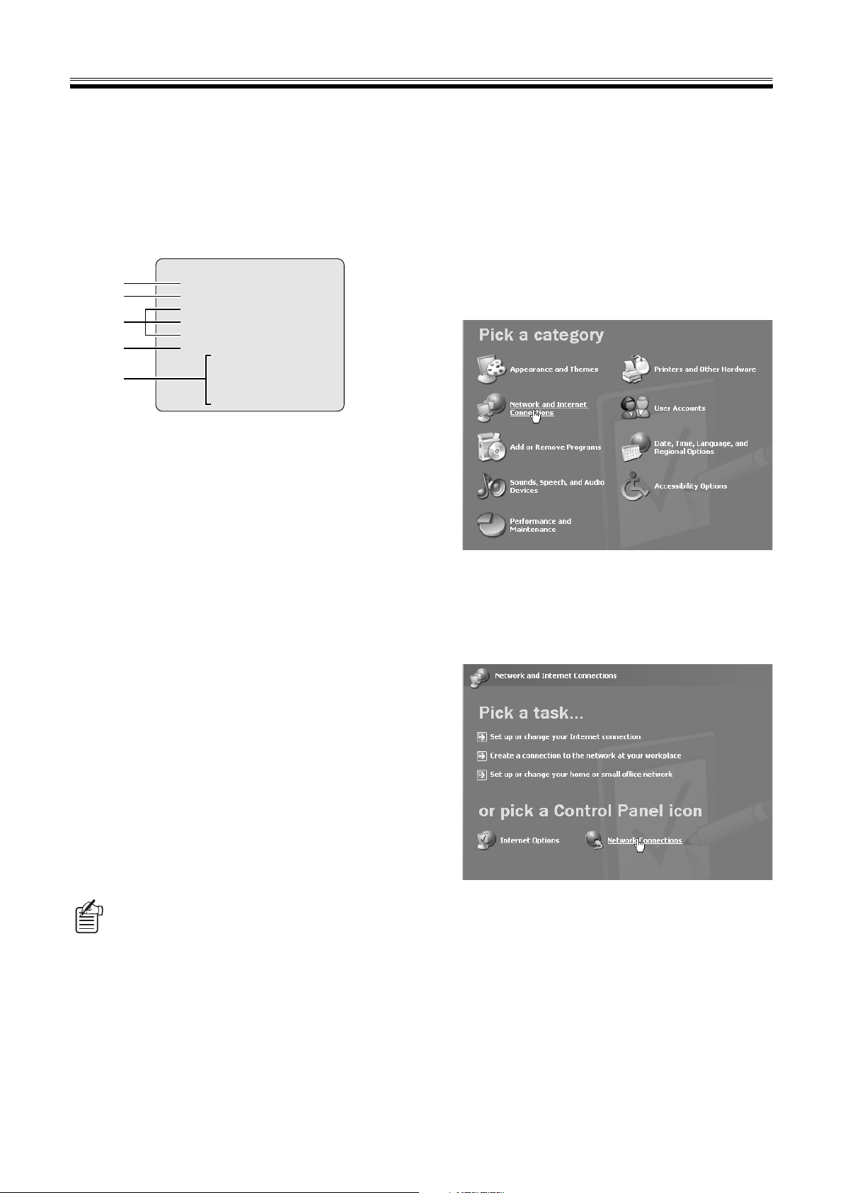
Click [Network and Internet Connections] of
1
[Control Panel].
The "Network and Internet Connections" screen will
display.
Click [Network Connections].
2
The "Network Connections" screen will display.
The settings of the LAN card being used (Ethernet
adapter) display in the [LAN or High-Speed Internet]
column.
The IP address, subnet mask, gateway, port, and
password settings can be changed using the
computer. (Refer to P34)
English 3
Network Connection Procedure
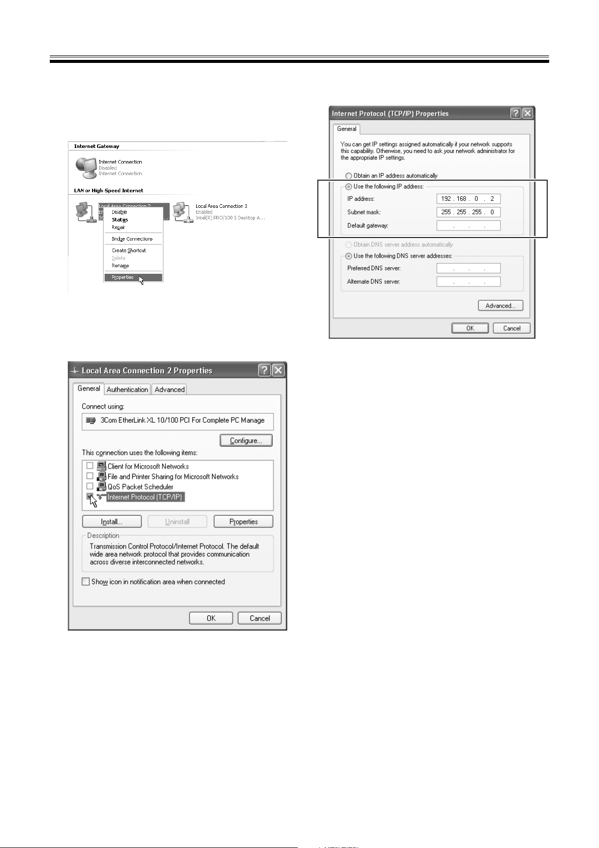
Right click the settings of the LAN card being
3
used (Ethernet adapter) and the select
[Properties] from the menu.
The [General] tab of [Local Area Connection
Properties] will display.
Select [Internet Protocol (TCP/IP)] from the list
4
of [This connection uses the following items].
Confirm that [Internet Protocol (TCP/IP)] is checked. If
it is not checked, add a check mark.
Select [Use the following IP address] and then
6
enter an IP address and subnet mask.
Confirm the setting contents and click [OK].
7
This ends the TCP/IP settings. Close all displayed
dialog boxes.
Click [Properties].
5
The [General] tab of [Internet Protocol (TCP/IP)
properties] will display.
4 English
Network Connection Procedure
3 Network Operation Screen Display
When the DVR and computer settings are complete, start the Web browser on the computer. The browser should be Internet
Explorer Ver. 5.5 SP2 or higher.
If the computer accesses the DVR following the procedure below, the screen will change to the network operation screen.
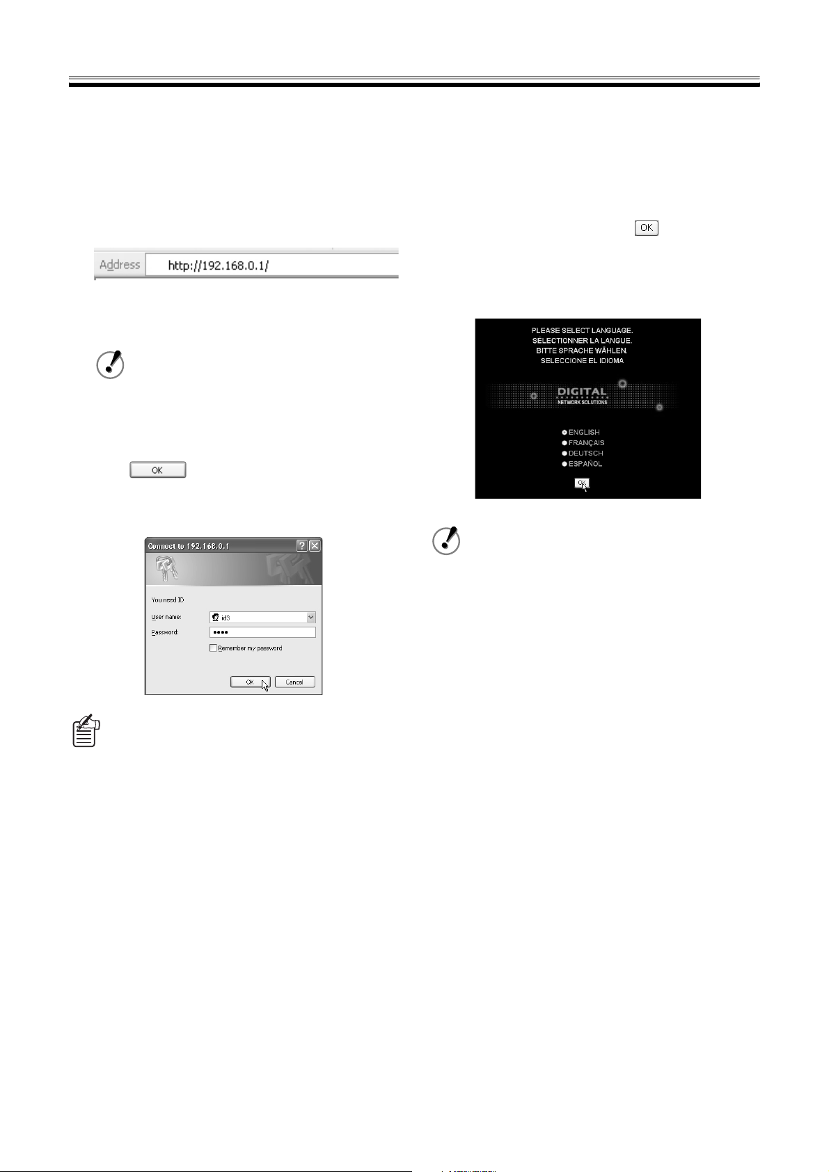
Enter the connection URL in the address bar
1
of the browser.
Enter the DVR IP address set in NETWORK SET after
http:// and press the [Enter] key. The authentication
check dialog box will display.
When PORT is set to a different value from the
initial "80" append a colon (:) and a PORT
number after the IP address.
<Example when setting PORT to 81>
http://192.168.0.1:81/
Enter the user name and password and then
2
click .
If the user name and password are entered correctly,
the connection to the DVR will complete and the
language selection screen will display.
• There is no distinction between uppercase and
lowercase.
• If [Remember my password] is checked after
entering the user name and password, entering
the password when connecting can be omitted
the next and subsequent times.
• Because the authentication check dialog box is
displayed when an operation outside the rights is
performed after connecting, it is also possible to
increase the user level while maintaining a
connected state. Cases when there are
restrictions on the connection rights due to
restrictions on the number of simultaneous
connections or network settings are excluded
from this. (Refer to P6)
Select a display language from the network
3
operation screen and click .
The screen will switch to the main screen and network
operations from the computer will be enabled.
Language selection:
English, French, German, Spanish
• Concerning the time setting of the DVR
If the current date and time are not set properly
on the DVR, basic operations such as normal
recording, timer controlled recording, camera
control will not be available. It will also hinder the
setting of other menus related to time and date.
Therefore, please verify whether the current date
and time are properly set on the DVR using the
CLOCK SET screen. (Refer to P24)
• If [NETWORK STATUS] is "ON" in NETWORK
SET of this device when changing to network
operation, the message " NETWORK CONTROL"
will be displayed on the screen of the monitor
connected to the DVR.
• When "Run Time Error" of Java Script
displays while using Internet Explorer
Select the menus in the following order [Tools] →
[Internet Options] → [Advanced Settings] and
then remove the check mark of "Display
notification for each script error" in the browser
settings. Check "Do not use script debugging".
• When a portion of the image is not displayed
due to performance or specifications of the
computer.
Within Internet Explorer select from the menus in
the following order [Tools] → [Internet Option] →
"Temporary Internet Files" and then set [Amount
of disk space to use] to less.
English 5
Network Connection Procedure
bNetwork Connection Restrictions
Connections are restricted depending on the connections
state of users and the content of the network settings. If a
DVR cannot be connected, confirm whether the connection
falls under the following restrictions.
Restrictions on the number of simultaneous
connected users
There is a limit to the number of users who can connect
simultaneously.
When a connection is not possible due to restrictions on the
number of simultaneous connections, the message "THE
UNIT IS BUSY!" will display.
1 Up to four users can connect simultaneously to one
DVR.
2 Only one user of either ID2 or ID3 can connect.
3 When a connection is duplicated, the user with the
higher user level will take precedence.
Example:
• If an ID1 user attempts to connect at the same time
as four other ID1 users, the connection will not be
allowed.
• If an ID2 user attempts to connect at the same time
as four other ID1 users, the ID1 user who connected
last will be disconnected and the ID2 user will be
allowed to connect in the ID1 users' place.
• If an ID3 user attempts to connect at the same time
as three other ID1 user and an ID2 user, since ID2
and ID3 users are not able to connect simultaneously,
the ID2 user will be disconnected and the ID3 user
will be allowed to connect in the ID2 user's place.
bChange to DVR Operation
If the disconnect button on the operation panel is clicked,
the network connection will disconnect and the DVR can be
operated.
When the connection is disconnected, the message "THE
UNIT IS DISCONNECTED!" will display.
Disconnect
button
• If the browser is closed without clicking the
disconnect button, approximately 1 minute
will pass until reconnecting.
• When [NETWORK CONTROL] of NETWORK
SET of the DVR is set to "ON (NETWORK)",
press the [EXIT/OSD] button for at least 2
seconds. The connection can be forcibly
disconnected from the DVR. The connection
will not be accepted from the computer for 10
seconds after a forced disconnect.
EXIT/OSD
Restrictions determined by network settings
Connection is restricted by the [NETWORK CONTROL]
settings of NETWORK SET of the DVR.
When a connection is not possible due to operation
restrictions established by NETWORK SET or the operating
state of the DVR, the message "THE UNIT IS NOT
READY!" will display.
1 When "ON (NETWORK)" is selected.
• All users (ID1 to ID3) can connect.
• Cannot connect during DVR playback, camera
control, and while displaying menu screens.
2 When "ON (DVR)" is selected.
• Only user level ID1 can connect. Only monitoring of live
video on the computer is possible.
• Cannot connect while the DVR is in playback
operation.
• If the playback operation is performed by the DVR
when connected, the connection will be automatically
disconnected.
3 When "OFF" is selected.
Cannot connect to DVR.
• When communication with the computer is
cut off for approximately 1 minute or more,
the connection will automatically disconnect
and switch to DVR operation.
• The connection will automatically disconnect
when the settings of NETWORK SET of the
DVR are changed while connected.
6 English
Organization of the Main Screen and
D
C
Functions of Each Part
The main screen will display when the network connection is completed. The main screen consists of three panels. The
operation panel is where you can perform basic operations, such as monitoring live video, recording, and playback.
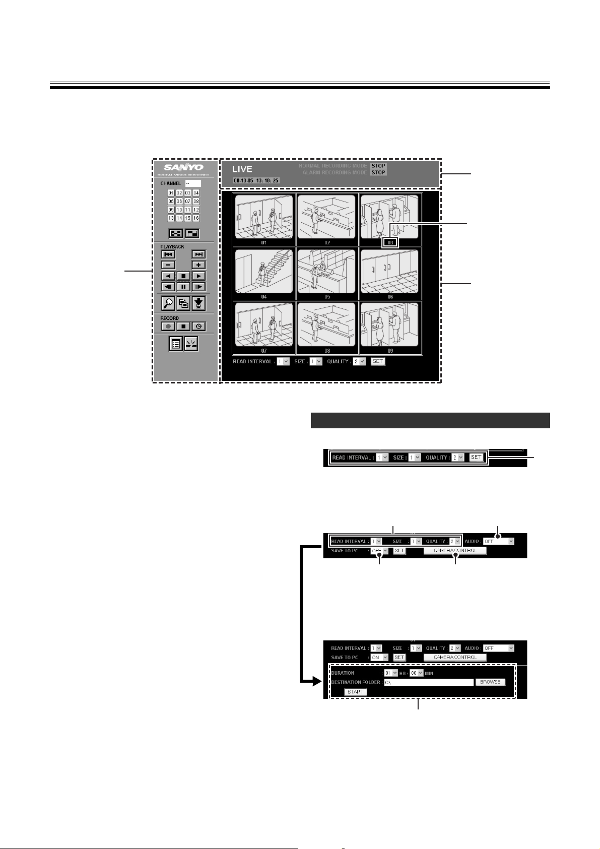
bOrganization of Main Screen
2
Camera title
1
3
1 Operation panel (Refer to P8)
In the operation panel, you can execute basic functions
of network operation at the touch of one button, such as
selecting a display channel or screen pattern, playback
and recording, or changing to other operation screens.
The operation panel is always displayed even if you
change from the main screen to other operation screens.
2 Operating mode display panel (Refer to P9)
This panel displays information related to display images
and the operating state of the DVR.
3 Image display panel (Refer to P10)
This panel displays live video and playback images. The
display pattern (full screen/quad-screen/multi-screen) of
the screen can be changed using the buttons on the
operation panel.
An image setting menu and a save button display at the
lowermost portion of the image display panel.
The displayed menu and button change depending on
the display pattern of the screen and button operation as
shown in "Menu display of image display panel". (Refer
to the figure on the right)
Menu display of image display panel
b Quad-screen/multi-screen
A
A Display speed, size, and image quality settings
(Refer to P11)
b Full screen
AB
A Display speed, size, and image quality settings
(Refer to P11)
B Audio playback (Refer to P11)
C Dome camera operation (Refer to P21)
D Saving live video to the computer (Refer to P17)
English 7
Setting menu for saving
Setting [SAVE TO PC] (D) to "ON" and clicking on [SET]
displays the saving set menu.
Organization of the Main Screen and Functions of Each Part
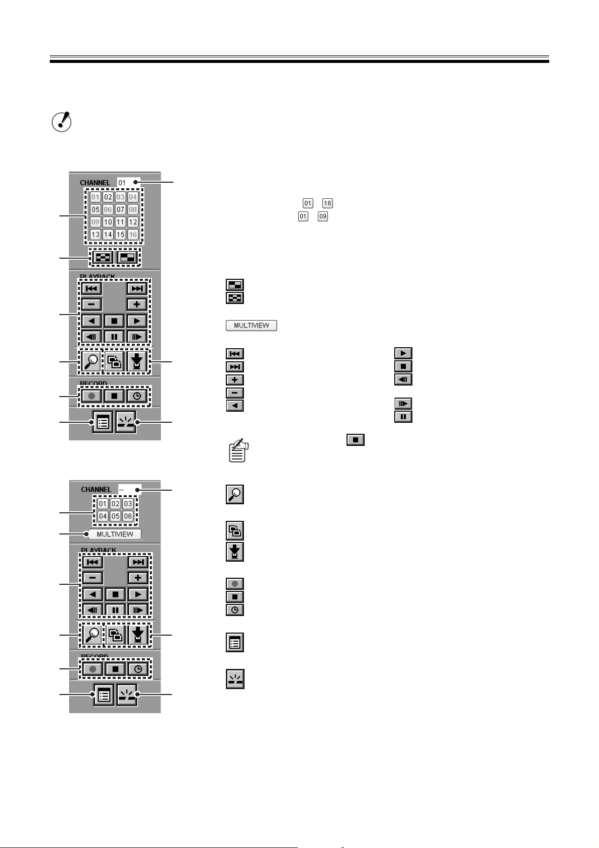
1 Functions of Operation Panel and Operation Authority
Click a button on the operation panel to perform operation through the network from the computer.
• The organization of the buttons on the operation panel differs depending on the DVR model.
• The button operations are restricted according to the level of the connected users. User levels which can
operate the buttons are displayed in ( ). (Refer to P34)
(9/16-channel model)
2
1
3
4
56
7
8
The included example uses the
16-channel model.
9
1 Channel selection button (ID1/2/3)
Click to display on full screen.
The layout of the buttons varies according to the DVR model.
16-channel model: 9-channel model: -
2 Channel display box
The selected channel number is displayed.
3 Screen select button (ID1/2/3)
Click to change the screen for a 9/16-channel model.
: Change to quad-screen
: Change to multi-screen (9/16 split screens).
Click to change the screen for a 6-channel model.
: Change to multi screen (6 split screens).
4 Playback operation button (ID2/3)
: Skip to previous alarm
: Skip to next alarm
: Increase playback speed
: Reduce playback speed
: Reverse playback
Displays a live video if is clicked during playback or while another
operation screen is displayed.
: Playback
: Stop playback
: Move frame to previous still
image
: Move frame to next still image
: Pause
(6-channel model)
5 Image search button (ID2/3)
2
: Change to SEARCH menu screen
1
3
4
6 Save operation button (ID2/3)
: Change to COPY screen
: Change to DOWNLOAD screen
7 Record operation button (ID3)
: Start normal recording
: Stop normal recording
: Change the timer controlled recording function
8 Menu button (ID3)
56
: Change to MAIN MENU screen
7
8
9
9 Disconnect button (ID1/2/3)
: Disconnect the connection with the DVR and change from network
operation to DVR operation.
8 English
Organization of the Main Screen and Functions of Each Part
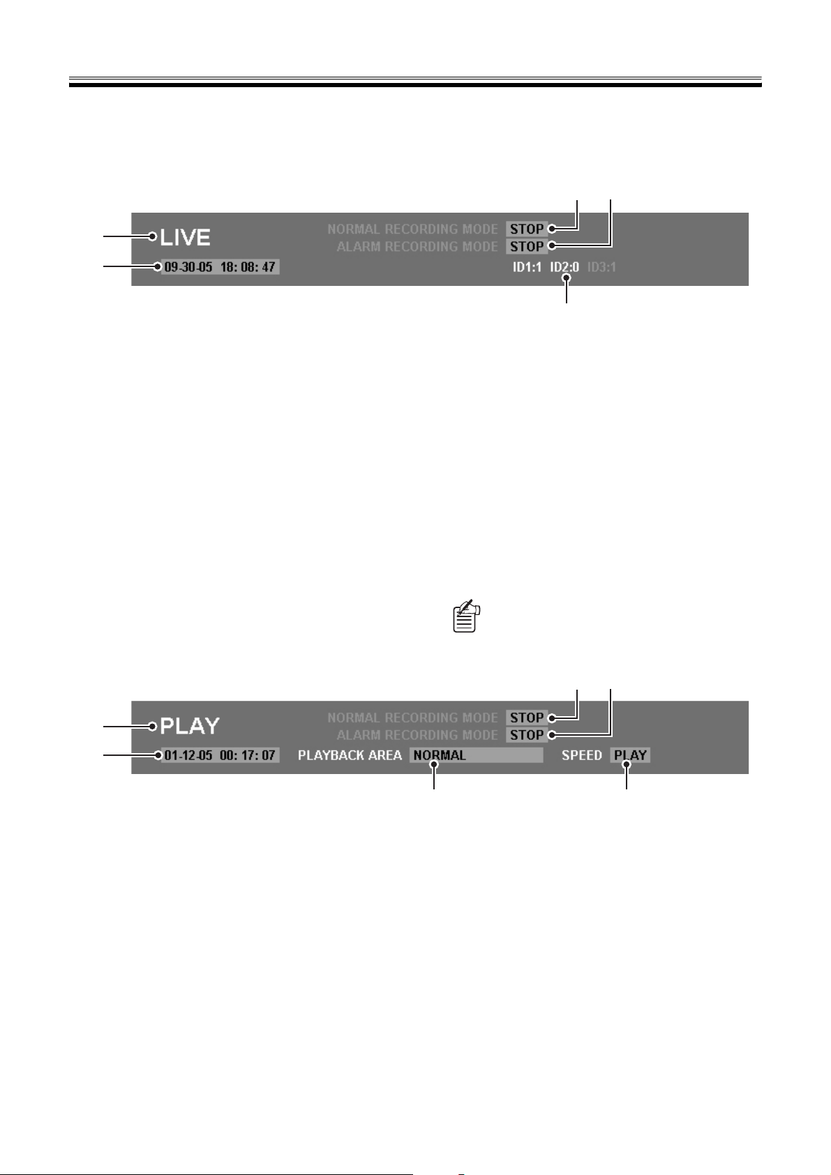
2 Operating mode display panel
Information required for network operation is displayed in this panel in response to the display image.
A For live video
34
1
2
5
1 Image classification
"LIVE" is displayed.
2 Date and time
Current date and time are displayed.
3 NORMAL RECORDING MODE
The operating mode of normal recording for the DVR is
displayed.
• STOP (stop recording state)
• RECORDING (while recording)
• TIMER STANDBY (during a timer recording standby)
• TIMER RECORDING (during timer recording)
• AREA FULL
[OVERWRITE] is set to "OFF" and the normal
recording area is full.
B When playing back images
1
4 ALARM RECORDING MODE
The operating mode of alarm recording for the DVR is
displayed.
• STOP (stop recording state)
• PRE ALARM RECORDING (during pre-alarm
recording)
• ALARM RECORDING (during alarm recording)
• AREA FULL
[OVERWRITE] is set to "OFF" and the alarm
recording area is full.
5 Connection information of user
When multiple users connect simultaneously, the
number of connected users will be displayed according
to the level of each user.
(Display example) ID1: 3 ID2: 1 ID3: 0
Your own user ID during the current operation is
displayed in red.
34
2
1 Image classification
"PLAY" is displayed.
2 Date and time
The recording date and time (time stamp) of the image
currently being played back is displayed.
3 NORMAL RECORDING MODE
The operating state of normal recording for the DVR is
displayed. (Display content is the same as a live video.)
4 ALARM RECORDING MODE
The operation state of alarm recording for the DVR is
displayed. (Display content is the same as a live video.)
English 9
5
5 PLAYBACK AREA
The recording area of the image currently being played
back is displayed.
• NORMAL (normal recording area)
• ALARM (alarm recording area)
• PRE ALARM (pre-alarm recording of alarm recording
area)
• ARCHIVE (archive area)
6 SPEED
The operating mode used during playback is displayed.
• PLAY (playback)
• STILL (pause)
• R. PLAY (reverse
playback)
• CUE (fast forward)
6
• REVIEW (fast reverse)
• SLOW (slow motion
playback)
• R. SLOW (reverse slow
motion playback)
View Live Video
If you change to network operation, live video will be automatically displayed in the image display panel of the main screen.
Click in the operation panel during playback or when another operation screen is displayed.
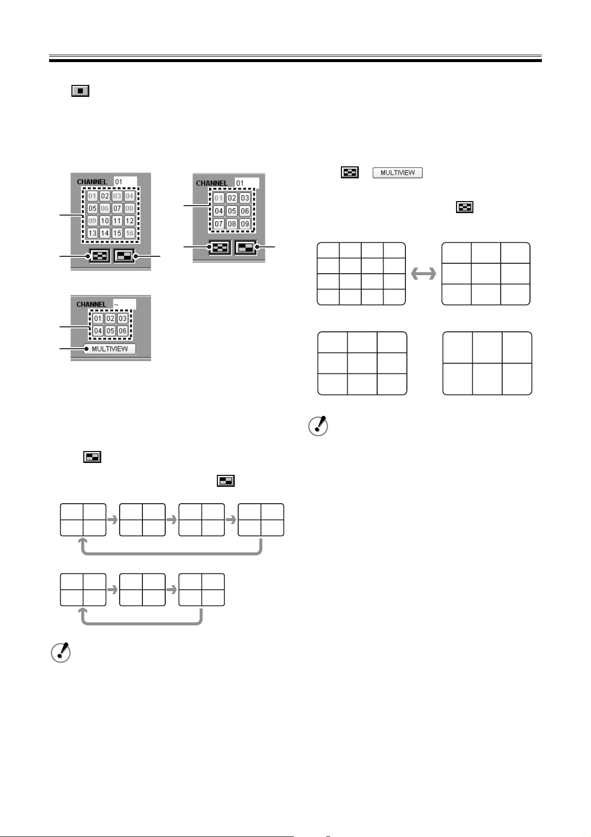
1 Change display pattern of live video (ID1/2/3)
The display pattern of live video can be selected from full screen (specific channel), quad-screen, or multi-screen.
(16-channel model) (9-channel model)
1
1
3
3
(6-channel model)
2
1
3
1 Full screen viewing
Click the channel selection button or click on a channel
image in the quad-screen or multi-screen. The specified
channel image will display in full screen.
2 Quad-screen viewing
(only corresponds to 9/16-channel model)
Click . Displays the camera image connected to the
DVR every four channels in order of the channel number.
The screen pattern changes each time is clicked.
• 16-channel model
CH01 CH02
CH03 CH04
CH05 CH06
CH07 CH08
CH09 CH10
CH11 CH12
CH13 CH14
CH15 CH16
2
3 View multi-screen (6/9/16 screens)
Click or . Display image in
multi-screen of 6/9/16 screens in response to the model
of DVR.
On the 16-channel model, clicking switches the
screen alternately from the 16 screen to the 9 screen.
• 16-channel model
CH01 CH02 CH03 CH04
CH05 CH06 CH07 CH08
CH09 CH10 CH11 CH12
CH13 CH14 CH15 CH16
• 9-channel model • 6-channel model
CH01 CH02 CH03
CH04 CH05 CH06
CH07 CH08 CH09
CH01 CH02 CH03
CH04 CH05 CH06
CH07 CH08 CH09
CH01 CH02 CH03
CH04 CH05 CH06
• Camera images are assigned in order of
channel number in a multi-screen. (It is not
affected by the SCREEN SET of the DVR)
• The audio can only be played back when full
screen is used.
• The image display speed in the quad-screen
and multi-screen differs depending on the
network environment.
• 9-channel model
CH01 CH02
CH03 CH04
CH05 CH06
CH07 CH08
CH09 CH01
CH02 CH03
For a 6 channel DVR, the quad-screen will not
display. Select from two patterns; full screen and
multi-screen.
10 English
View Live Video
3
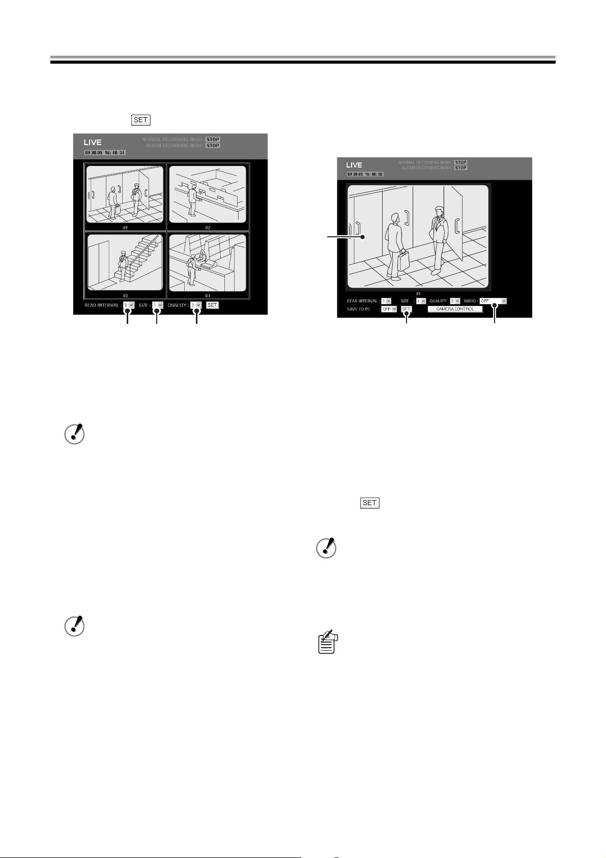
2Set the display mode for images (ID1/2/3)
You can set the display mode for live video and played back
images. Select a setting value from the pull-down menu of
each item and click .
12 3
1 READ INTERVAL (Initial setting: 1)
The display speed for images can be selected in five
levels. The larger the numeric value, the faster the
speed.
The actual display speed is influenced by the network
environment.
The display speed cannot be set when
[AUDIO] is set to "ON".
3Playback audio (ID2/3)
You can playback live and audio of reproduced audio at the
same time.
When playing back audio, be sure the optional application
software "DVR Viewer2 (Ver.2.0.0 or higher)" is installed on
the computer beforehand. (Refer to P36)
1
23
Click the channel selection button.
1
The screen will become the full screen display and the
setting menu for [AUDIO] will display.
Set [AUDIO] to "ON".
2
Audio data is played back after being buffered for a
fixed time. When [AUDIO] is set to "ON",
simultaneously select a buffering time.
2 SIZE (Initial setting: 1)
The image display size can be selected from six levels.
The larger the numeric value, the larger the image.
3 QUALITY (Initial setting: 2)
The image quality of live video can be selected in three
levels.
The selected image quality is applied to all channel
images connected to the DVR.
Selections:
1: Low image quality
2: Standard image quality
3: High image quality
Because image quality cannot be selected
when playing back images, the setting menu
for [QUALITY] is not displayed.
Selections:
• OFF (initial setting)
• ON-5/10/15/20/30 (seconds)
Click .
3
The audio of the image will playback.
• The audio cannot be played back in the
quad-screen and multi-screen.
• When playing back images with audio
attached, the audio will take precedence and
playback. Because of this, there is also a
possibility that the images will not display
depending on the environment.
What is buffering?
Buffering reads data in advance and saves a certain
amount.
If the buffering time is set to be long, the playback
quality will improve but time lags (delays) in the
audio will occur.
English 11
Recording Monitored Images
You can record images while they are being monitored onto the hard disk of the DVR.
There are four methods to record, normal recording, timer-controlled recording, alarm recording and pre-alarm recording. The
stored images are recorded on each recording area in response to the operation.
• Because all connected camera images are recorded by the corresponding DVR, the channel cannot be
specified.
• If the clock of the DVR is not set, it is not possible to record. (Refer to P24)
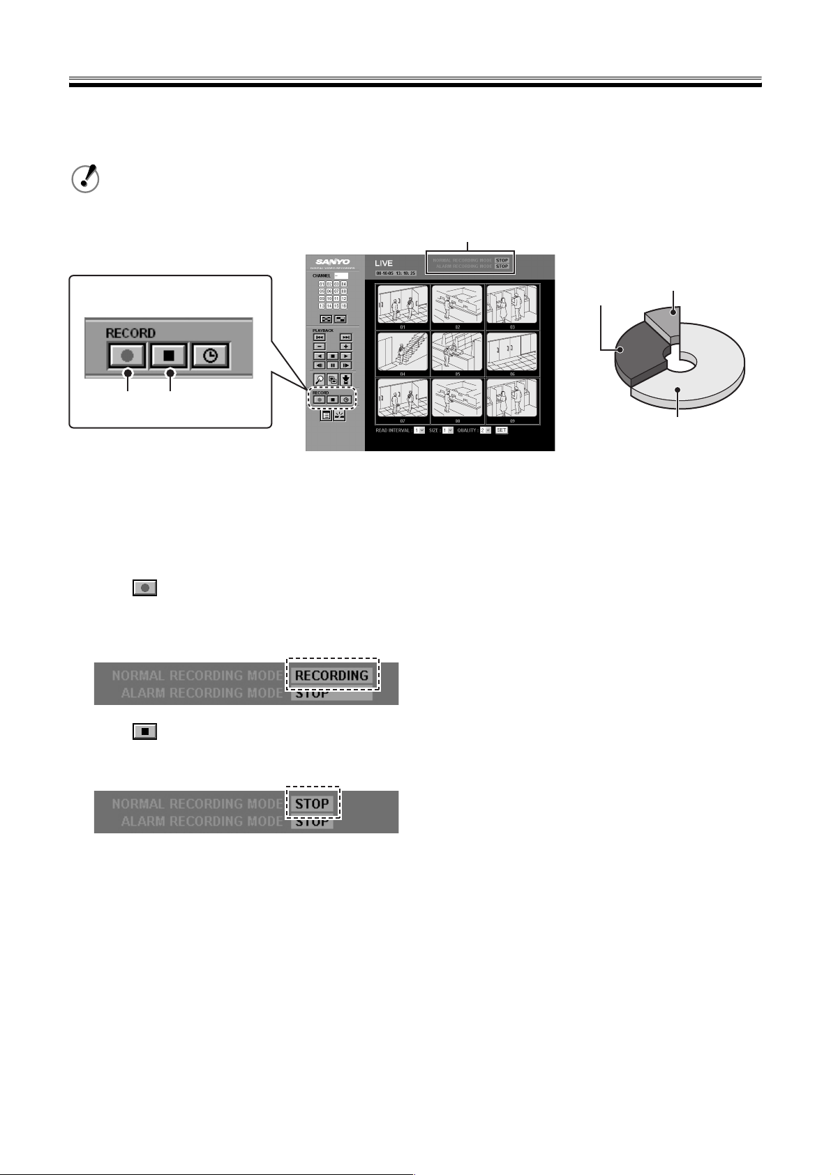
Operating mode display
(User level: ID3)
Operation panel
1 2
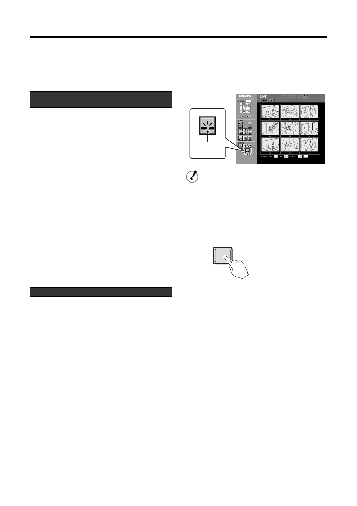
bNormal Recording
(Normal Recording Area)
Records images being monitored using the manual
operation on the operation panel.
Click .
1
The display [NORMAL RECORDING MODE] in the
operating mode display will change to "RECORDING"
and recording will start.
Click when the recording stops.
2
The display [NORMAL RECORDING MODE] will
change to "STOP" and recording will stop.
Alarm
recording area
Archive area
Normal recording area
bOther Recording Methods
Set the recording conditions in the DVR setting menu. Refer
to the applicable pages for details.
☞ Timer-controlled recording (normal recording area)
Images being monitored are automatically recorded
according to the timer setting. (Refer to P28)
☞ Alarm recording (alarm recording area)
Uses signals from motion sensors and external devices
(such as door switches and infrared sensors) to
automatically record alarm images (such as
intruders). (Refer to P30)
☞ Pre-alarm recording (alarm recording area)
If pre-alarm recording is set, the most recent images of a
fixed time will constantly be recorded in the alarm
recording area while being repeatedly overwritten. You
can view images which occur just before an alarm when
playing back alarm recordings. (Refer to P30, 31)
12 English
 Loading...