

Page 1
Digital Video Recorder
DSR-3000P
Instruction Manual
Bedienungsanleitung
Manuel d’instructions
Manual de Instrucciones
Manuale di Istruzioni
English GB
Deutsch D
Français F
Español E
Italiano I
About this manual
Before installing and using this unit, please read this
manual carefully. Be sure to keep it handy for later
reference.
Über diese Anleitung
Lesen Sie bitte diese Bedienungsanleitung vor der
Installation und der Verwendung des Gerätes sorgfältig
durch. Bewahren Sie die Anleitung zum späteren
Nachschlagen auf.
À propos de ce manuel
Avant d’installer et d’utiliser cet appareil, veuillez lire ce
manuel attentivement. Assurez-vous de le garder à
portée de la main pour référence ultérieure.
Acerca de este manual
Antes de instalar y usar este aparato, lea detenidamente
este manual. Asegúrese de guardarlo a mano para
futuras referencias.
Nota su questo manuale
Leggere attentamente questo manuale prima di passare
all’installazione ed all’uso di questo apparecchio.
Conservare il manuale in un posto sicuro per riferimenti
futuri.
Page 2

PRECAUTION
WARNING: TO REDUCE THE RISK OF FIRE OR
ELECTRIC SHOCK, DO NOT EXPOSE THIS
APPLIANCE TO RAIN OR OTHER MOISTURE.
To avoid electrical shock, do not open the cabinet.
Refer servicing to qualified personnel only.
If the power supply cord (AC power cord) of this
appliance is damaged, it must be replaced. Return
to a SANYO Authorised Service Centre for
replacement of the cord.
Location
For safe operation and satisfactory performance of your
unit, keep the following in mind when selecting a place for
its installation:
Shield it from direct sunlight and keep it away from sources
of intense heat.
Avoid dusty or humid places.
Avoid places with insufficient ventilation for proper heat
dissipation. Do not block the ventilation holes at the top and
bottom of the unit. Do not place the unit on a carpet
because this will block the ventilation holes.
Install the unit in a horizontal position only.
Avoid locations subject to strong vibrations.
Avoid moving the unit between cold and hot locations.
Do not place the unit directly on top of a monitor TV, as this
may cause playback or recording problems.
Avoiding Electrical Shock and Fire
Do not handle the power cord with wet hands.
Do not pull on the power cord when disconnecting it from an
AC wall outlet. Grasp it by the plug.
If any liquid is spilled on the unit, unplug the power cord
immediately and have the unit inspected at a
factory-authorised service centre.
Do not place anything directly on top of this unit.
SERVICE
This unit is a precision instruments and if treated with care,
will provide years of satisfactory performance. However, in
the event of a problem, the owner is advised not to attempt
to make repairs or open the cabinet. Servicing should
always be referred to your dealer or Sanyo Authorized
Service Centre.
CAUTION
Danger of explosion if battery is incorrectly replaced.
Replace only with the same or equivalent type
recommended by the manufacturer.
Discard used batteries according to the manufacture’s
instructions.
English
1
Page 3

CONTENTS
MAIN FEATURES . . . . . . . . . . . . . . . . . . . . . . . . . . . . . . . . . . . . . . . . . 4
ACCESSORIES . . . . . . . . . . . . . . . . . . . . . . . . . . . . . . . . . . . . . . . . . . . 4
PART NAMES . . . . . . . . . . . . . . . . . . . . . . . . . . . . . . . . . . . . . . . . . . 5
Front panel. . . . . . . . . . . . . . . . . . . . . . . . . . . . . . . . . . . . . . . . . . . . . . .
Rear panel . . . . . . . . . . . . . . . . . . . . . . . . . . . . . . . . . . . . . . . . . . . . . . .
CONNECTIONS . . . . . . . . . . . . . . . . . . . . . . . . . . . . . . . . . . . . . . . . . 7
Basic connections. . . . . . . . . . . . . . . . . . . . . . . . . . . . . . . . . . . . . . . . .
System control connections . . . . . . . . . . . . . . . . . . . . . . . . . . . . . . . .
Connecting a remote control circuit . . . . . . . . . . . . . . . . . . . . . . . . . .
Digital multiplexer connections . . . . . . . . . . . . . . . . . . . . . . . . . . . . . .
Digital series connections . . . . . . . . . . . . . . . . . . . . . . . . . . . . . . . . . .
BUILT-IN HARD DISK . . . . . . . . . . . . . . . . . . . . . . . . . . . . . . . . . . . . 9
Hard disk . . . . . . . . . . . . . . . . . . . . . . . . . . . . . . . . . . . . . . . . . . . . . . . .
Recording speed tables . . . . . . . . . . . . . . . . . . . . . . . . . . . . . . . . . . . .
Operating display . . . . . . . . . . . . . . . . . . . . . . . . . . . . . . . . . . . . . . . . .
10
11
RECORDING IMAGES IN THE NORMAL RECORDING AREA . . . 12
Normal recording. . . . . . . . . . . . . . . . . . . . . . . . . . . . . . . . . . . . . . . . . .
Timer recording . . . . . . . . . . . . . . . . . . . . . . . . . . . . . . . . . . . . . . . . . . .
12
13
RECORDING IMAGES IN THE ALARM RECORDING AREA . . . . . 15
Alarm recording. . . . . . . . . . . . . . . . . . . . . . . . . . . . . . . . . . . . . . . . . . .
Pre-alarm recording . . . . . . . . . . . . . . . . . . . . . . . . . . . . . . . . . . . . . . .
15
16
PLAYING BACK IMAGES RECORDED IN THE NORMAL
RECORDING AREA . . . . . . . . . . . . . . . . . . . . . . . . . . . . . . . . . . . 18
SEARCHING FOR RECORDED IMAGES. . . . . . . . . . . . . . . . . . . . . 23
SAVING (COPYING) RECORDED IMAGES . . . . . . . . . . . . . . . . . . . 32
Copying images to the hard disk archive area. . . . . . . . . . . . . . . . . .
Copying images from archive area to a CompactFlash card . . . . . .
CompactFlash recording area . . . . . . . . . . . . . . . . . . . . . . . . . . . . . . .
Copying to a DDS (Digital Data Storage) drive. . . . . . . . . . . . . . . . . .
32
33
34
35
MENU FLOW CHART AND MENU OPERATIONS. . . . . . . . . . . . . . 38
MENU flow . . . . . . . . . . . . . . . . . . . . . . . . . . . . . . . . . . . . . . . . . . . . . . .
Basic menu screen operations . . . . . . . . . . . . . . . . . . . . . . . . . . . . . .
Operations while a sub-menu screen is displayed . . . . . . . . . . . . . .
38
39
39
LANGUAGE/CLOCK SET SETTINGS . . . . . . . . . . . . . . . . . . . . . . . 40
Setting the language . . . . . . . . . . . . . . . . . . . . . . . . . . . . . . . . . . . . . . .
CLOCK SET settings. . . . . . . . . . . . . . . . . . . . . . . . . . . . . . . . . . . . . . .
SUMMER TIME SET setting . . . . . . . . . . . . . . . . . . . . . . . . . . . . . . . . .
EXT. CLOCK SET setting . . . . . . . . . . . . . . . . . . . . . . . . . . . . . . . . . . .
40
40
41
41
VIDEO INPUT SET SETTING . . . . . . . . . . . . . . . . . . . . . . . . . . . . . . 42
MULTIPLEXER setting . . . . . . . . . . . . . . . . . . . . . . . . . . . . . . . . . . . . .
VIDEO INPUT setting. . . . . . . . . . . . . . . . . . . . . . . . . . . . . . . . . . . . . . .
42
42
RECORDING AREA SET SETTING . . . . . . . . . . . . . . . . . . . . . . . . . 43
TOTAL CAPACITY display . . . . . . . . . . . . . . . . . . . . . . . . . . . . . . . . . .
Resetting each recording area. . . . . . . . . . . . . . . . . . . . . . . . . . . . . . .
AREA FULL RESET setting . . . . . . . . . . . . . . . . . . . . . . . . . . . . . . . . .
43
43
44
5
6
7
7
7
8
8
9
2
English
Page 4

CONTENTS
RECORDING CONDITIONS SET SETTING . . . . . . . . . . . . . . . . . . . 45
Recording settings for digital series connection
(maximum 3 units). . . . . . . . . . . . . . . . . . . . . . . . . . . . . . . . . . . . . . . . .
Setting NORMAL RECORDING AREA OVERWRITE and
REMAINING DISK WARNING on the operating display section . . . .
45
46
NORMAL REC MODE SET SETTING . . . . . . . . . . . . . . . . . . . . . . . . 47
NORMAL REC MODE SET setting . . . . . . . . . . . . . . . . . . . . . . . . . . . .
47
TIMER SET SETTING . . . . . . . . . . . . . . . . . . . . . . . . . . . . . . . . . . . . 48
TIMER SET setting. . . . . . . . . . . . . . . . . . . . . . . . . . . . . . . . . . . . . . . . .
Timer reservations every day at the same time with the same
image quality . . . . . . . . . . . . . . . . . . . . . . . . . . . . . . . . . . . . . . . . . . . . .
Timer reservations spanning more than 24 hours. . . . . . . . . . . . . . .
48
48
50
HOLIDAY SET SETTING . . . . . . . . . . . . . . . . . . . . . . . . . . . . . . . . . . 51
HOLIDAY SET setting . . . . . . . . . . . . . . . . . . . . . . . . . . . . . . . . . . . . . .
51
ALARM REC MODE SET SETTING . . . . . . . . . . . . . . . . . . . . . . . . . 52
ALARM REC MODE SET setting . . . . . . . . . . . . . . . . . . . . . . . . . . . . .
Pre-alarm recording setting . . . . . . . . . . . . . . . . . . . . . . . . . . . . . . . . .
Alarm trigger setting . . . . . . . . . . . . . . . . . . . . . . . . . . . . . . . . . . . . . . .
Built-in motion sensor settings . . . . . . . . . . . . . . . . . . . . . . . . . . . . . .
52
54
55
55
DISPLAY SET SETTING . . . . . . . . . . . . . . . . . . . . . . . . . . . . . . . . . . 57
DISPLAY SET setting . . . . . . . . . . . . . . . . . . . . . . . . . . . . . . . . . . . . . .
VIDEO LOSS SET setting . . . . . . . . . . . . . . . . . . . . . . . . . . . . . . . . . . .
57
57
RS-232C/RS-485 SET SETTING . . . . . . . . . . . . . . . . . . . . . . . . . . . . 58
RS-232C/RS-485 SET setting . . . . . . . . . . . . . . . . . . . . . . . . . . . . . . . .
RS-232 Selection . . . . . . . . . . . . . . . . . . . . . . . . . . . . . . . . . . . . . . . . . .
RS-485 Selection . . . . . . . . . . . . . . . . . . . . . . . . . . . . . . . . . . . . . . . . . .
58
58
59
BUZZER SET SETTING. . . . . . . . . . . . . . . . . . . . . . . . . . . . . . . . . . . 60
SECURITY LOCK SET SETTING . . . . . . . . . . . . . . . . . . . . . . . . . . . 61
Operating privileges and security lock . . . . . . . . . . . . . . . . . . . . . . . .
A Administrator password setting . . . . . . . . . . . . . . . . . . . . . . . . . . . . .
B User password setting. . . . . . . . . . . . . . . . . . . . . . . . . . . . . . . . . . . . .
C Recording and playback operating privilege setting . . . . . . . . . . . .
D Security lock setting . . . . . . . . . . . . . . . . . . . . . . . . . . . . . . . . . . . . . .
61
61
62
63
63
NETWORK SET SETTING. . . . . . . . . . . . . . . . . . . . . . . . . . . . . . . . . 64
NETWORK SET setting . . . . . . . . . . . . . . . . . . . . . . . . . . . . . . . . . . . . .
PASSWORD SETTING setting . . . . . . . . . . . . . . . . . . . . . . . . . . . . . . .
64
65
HDD SET SETTING . . . . . . . . . . . . . . . . . . . . . . . . . . . . . . . . . . . . . . 67
HDD SET setting . . . . . . . . . . . . . . . . . . . . . . . . . . . . . . . . . . . . . . . . . .
Adding a hard disk . . . . . . . . . . . . . . . . . . . . . . . . . . . . . . . . . . . . . . . .
67
67
POWER FAILURE/USED TIME DISPLAY . . . . . . . . . . . . . . . . . . . . 68
INTERFACE SPECIFICATIONS . . . . . . . . . . . . . . . . . . . . . . . . . . . . 69
SPECIFICATIONS . . . . . . . . . . . . . . . . . . . . . . . . . . . . . . . . . . . . . . . 72
English
3
Page 5
MAIN FEATURES
This digital video recorder can be used to store images recorded by
a monitoring camera onto its built-in hard disk.
Equipped with a large-capacity 3.5-inch hard disk drive.
•
Recording and playback of images can be carried out using
•
digital signals from a multiplexer.
Playback can be carried out at the same time as recording.
•
Alarm recording tracks movements of suspicious individuals.
•
Timer recording lets you record different sessions each day.
•
Pre-alarm recording records the images immediately before an
•
alarm.
Audio recording and playback is also possible.
•
Has a built-in motion detector function that can trigger alarm
•
recording when movement is detected.
Recorded images can be copied using CompactFlash cards.
•
Includes a variety of search functions.
•
☞ Alarm searching using an alarm event list or thumbnail alarm
images
☞ Time and date searches based on recording date and time
☞ Motion sensor detecting by searching for the movement of a
suspicious individual
A zoom function allows images being monitored or played back to
•
be enlarged for display.
Images can be captured by field or by frame.
•
The image quality mode can be selected from five modes for both
•
field and frame.
Three levels of security lock are available.
•
A PCMCIA-compatible network card can be used to carry out
•
network control.
Includes an RS-232C interface for computer control.
•
Connection to a system controller (sold separately) is possible
•
using an RS-485 interface.
A PCMCIA-compatible SCSI card can be used for backups to
•
DDS (DAT) drives.
Setting-up environment
Leave a space of at least 5 cm between the digital video recorder
and other nearby objects.
Ventilation holes are located at both sides and on the base of the
digital video recorder. Do not allow these ventilation holes to be
covered when setting up the recorder.
Furthermore, avoid using the digital video recorder in places with
poor ventilation.
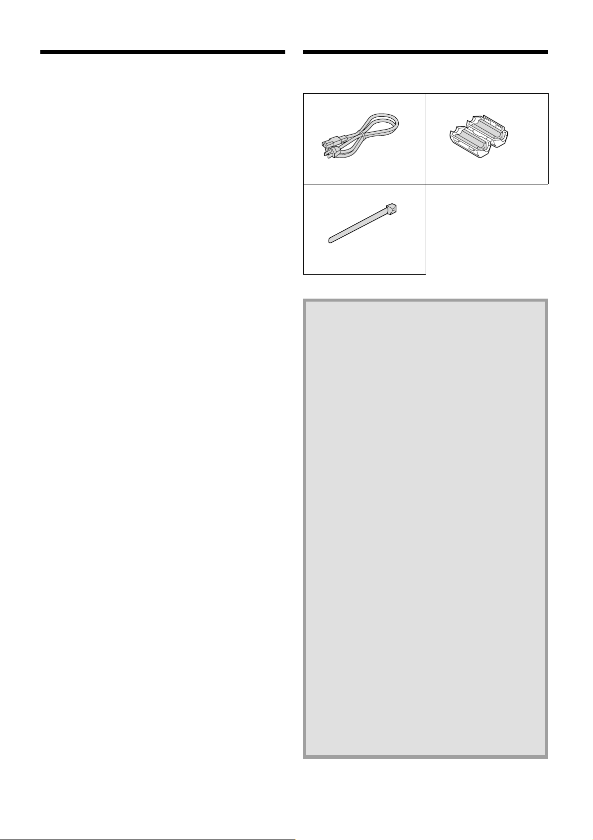
ACCESSORIES
Power cord Ferrite core
Fixer power cord tie
Hard disk protection
If any hard disk format errors are found when the power is
turned on, the whole hard disk is checked automatically. If any
further problems are found with the hard disk, the POWER
indicator flashes. Please contact the place of purchase if you
need to reformat the hard disk or make backups of any
images. The hard disk is very sensitive to dust, vibration and
shocks, and it should not be used in places near sources of
magnetic fields. Be sure to observe the following points in
order to prevent any loss of data.
Do not subject the digital video recorder to shocks.
•
Do not use the digital video recorder in places where it will
•
be subjected to vibration or places which are unstable.
Do not disconnect the power cord while recording or
•
playback is in progress.
Do not use in places which are subject to rapid changes in
•
temperature (changes of around 10°C in an hour).
If the digital video recorder is moved to a place with a
•
large difference in temperature or a high level of humidity,
condensation may form. If the digital video recorder is
used with condensation inside it, operating problems may
occur.
Do not install the digital video recorder in places which are
•
constantly vibrating, such as vehicles or trains.
The hard disk and cooling fan are
consumables.
These parts should generally be replaced after 2 years of
•
use (for the hard disk) or 3 years of use (for the cooling
fan) at normal temperatures of 25°C. These periods of
time are intended as guides only, and are not a guarantee
of product performance.
For important recordings
Always check whether a recording has been recorded
•
properly.
In case a recording was not recorded properly with this
•
unit because of faulty connections with other equipment or
a correct playback is not possible, any claims for
compensation will be declined.
For important recordings, it is recommended to make a
•
periodical backup copy for protection against loss from any
malfunction or accident.
4
English
Page 6

PART NAMES
Front panel
12345 786FGJK N
POWER indicator
1
POWER FULL
ALARM FULL
LOCK ALARM
Illuminates when the power cord plug is inserted into a wall outlet.
Flashes when there is a problem with the hard disk or fan.
FULL indicator
2
Flashes when the remaining space in the normal recording area
of the hard disk drops to 1%*. (* This can be changed using the
menu settings.)
ALARM FULL indicator
3
Flashes when the remaining space in the alarm recording area of
the hard disk drops to 1%*. (* This can be changed using the
menu settings.)
LOCK indicator
4
Illuminates when the security lock is engaged and operations are
locked.
If a button is pressed while the lock is engaged, the buzzer
sounds and the indicator illuminates.
ALARM indicator
5
Illuminates during pre-alarm recording.
Flashes during alarm recording.
MENU button and indicator
6
Used to display the menu screens (setting screens).
ZOOM button and indicator
7
Used to display the zoom screen during monitoring and playback.
The indicator illuminates when the zoom screen is displayed.
This does not operate when a multiplexer is connected digitally in
series.
CHANNEL button and indicator
8
If the digital video recorder is connected to a Sanyo multiplexer
that allows decoding of channel information (camera numbers),
channels can be specified so that only those channels are played
back. The indicator illuminates during playback. The CHANNEL
button can only be used during still mode.
REC/STOP button and indicator
9
Use to start normal recording.
The indicator illuminates during recording.
If the button is pressed for 2 seconds or more during recording,
recording stops and the indicator switches off.
EXIT/OSD button and indicator
F
•
When a menu screen is displayed
The main menu or sub-menu is exited.
•
During recording or playback
When the button is pressed during recording or playback,
superimposed information such as time and date and alarm
status changes in the following order:
Displayed at top-left → Displayed at bottom-left → Displayed
at top-right → Displayed at bottom-right → Off.
The indicator illuminates while information is displayed.
MENU
ZOOM
CHANNEL
REC/STOP
EXIT/OSD
PLAY/STOP
SEARCH
FRAME/FIELD
STILL
COPY
SHUTTLE HOLD
TIMER ALARM
SHUTTLE
E
N
JOG
R
T
A
E
L
C
E
R
O
P
9IHML
SEARCH FRAME/FIELD button and indicator
G
•
During recording or when stopped
When the button is pressed during recording or when the
digital video recorder is stopped, the indicator illuminates and
search playback is possible.
•
During playback
When the button is pressed during playback, the indicator
illuminates and the mode change to frame/field playback
mode.
COPY button and indicator
H
Used to copy images to the archive area of the hard disk or to a
CompactFlash card or microdrive.
The indicator illuminates during copying.
TIMER button and indicator
I
When the button is pressed when recording is stopped, the digital
video recorder switches to timer recording standby mode, and
when the setting time is reached, timer recording starts.
PLAY/STOP button and indicator
J
When the button is pressed, the indicator illuminates and
playback of images in the normal recording area starts.
If pressed during playback, playback stops.
STILL button and indicator
K
When this button is pressed during playback, the indicator
illuminates and playback pauses. If it is pressed again, playback
resumes.
SHUTTLE HOLD button and indicator
L
This locks the speed for playback and frame advance.
The indicator illuminates while locked.
ALARM buttons (û ALARM ù)
M
When these buttons are pressed during playback, playback skips
to the previous or next alarm recording.
Jog (inner) and shuttle (outer) dials
N
•
During playback
The jog dial changes the playback speed.
The shuttle dial fast-forwards and rewinds.
•
Menu screens
The jog dial moves the cursor and changes settings.
The shuttle dial accepts settings.
CompactFlash card slot
O
Insert a CompactFlash card or microdrive here.
MENU RESET button
P
Reinitializes menu settings.
English
5
Page 7
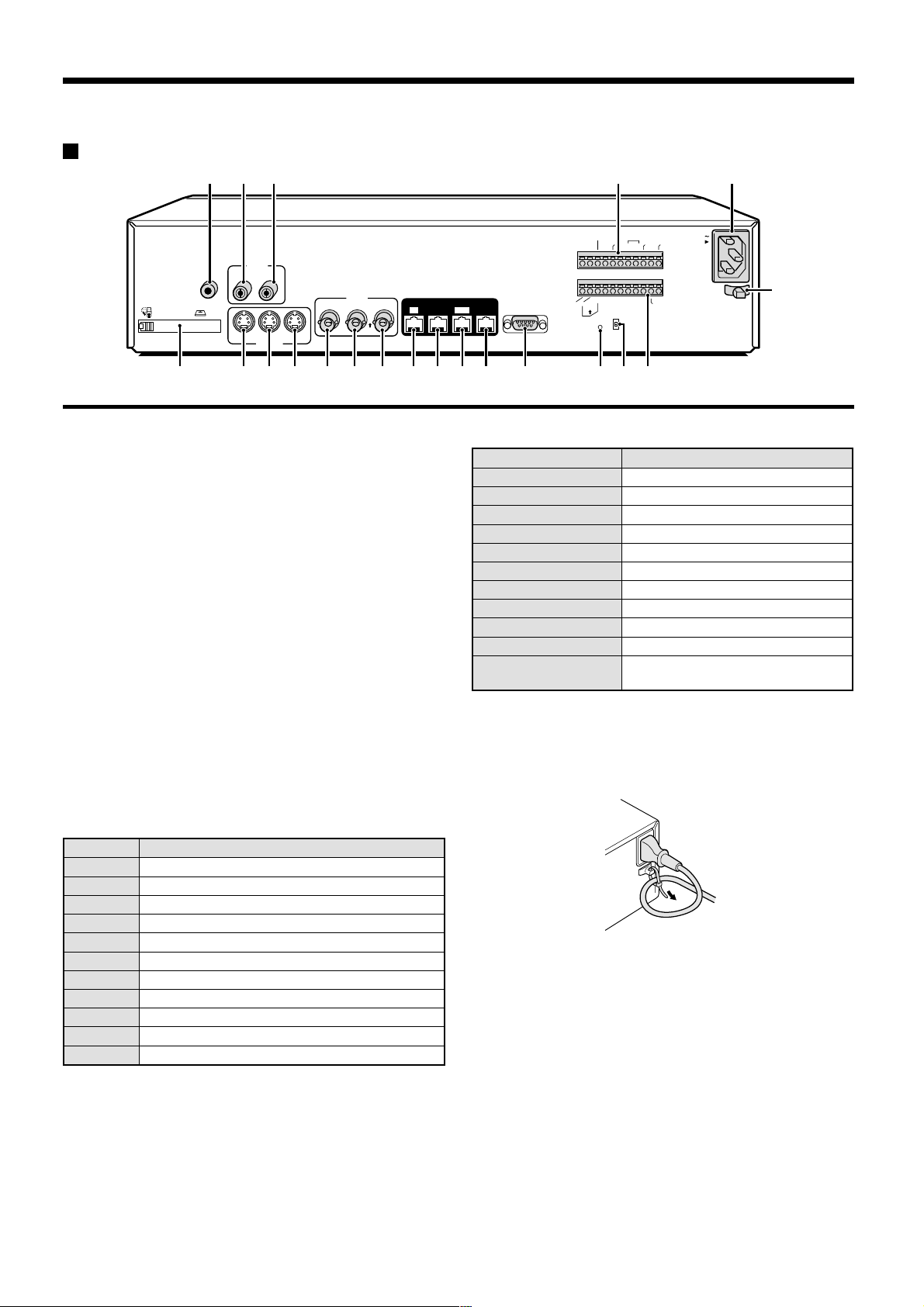
Rear panel
EJECT
PC Card SLOT
234 O P
ALARM
CLOCK
ADJUST
RESET
NON REC
OUT
ALARM
ALARM
OUT
IN
C
C
AUDIO
MIC
IN
IN
OUTIN
LOOP OUT
S-VIDEO
VIDEO
LOOP OUT
IN
OUT
OUT
DIGITAL
OUT
SUB IN
IN
SUB OUT
RS232C
RS485
NCCC
B
REMOTE
AONC
RS485
TERMINATE
ALL
RESET
OFF
OUT
WARNING
FULLOUTIN
SW OUT
AC IN
ALARM
FULL
CCNC
NMLKJIHGF987651
Q
PC card slot
1
Connect a network card or SCSI card (sold separately) here.
MIC IN terminal
2
AUDIO IN terminal
3
AUDIO OUT terminal
4
S-VIDEO IN terminal
5
S-VIDEO LOOP OUT terminal
6
S-VIDEO OUT terminal
7
VIDEO IN terminal
8
Images being input to the S-VIDEO IN terminal take priority.
VIDEO LOOP OUT terminal
9
VIDEO OUT terminal
F
DIGITAL VIDEO IN terminal
G
DIGITAL VIDEO OUT terminal
H
DIGITAL VIDEO SUB IN terminal
I
DIGITAL VIDEO SUB OUT terminal
J
RS-232C terminal
K
ALL RESET button
L
RS-485 termination switch
M
Control connector
N
Pin Signal
C Ground
A RS-485 connector*
B RS-485 connector*
C Ground
REMOTE Remote control input
C Ground
NC Spare
NC Spare
C Ground
SW OUT Switching output
C Ground
Alarm connector
O
Pin Signal
C Ground
ALARM IN Alarm input
ALARM RESET Alarm reset input
ALARM OUT Alarm output
NON REC OUT Non-rec output
C Ground
CLOCK ADJUST IN Clock sync input (See page 41.)
CLOCK ADJUST OUT Clock sync output (See page 41.)
WARNING OUT Hard disk error warning output
FULL Hard disk space warning output
ALARM OUT Alarm recording area space warning
output
AC power socket (AC IN~)
P
Securely insert the accessory power cord here.
Power cord holder
Q
Secure the power cord to the holder using the accessory cord tie
as shown in the illustration.
* Used for twisted-pair cable connection.
6
English
Page 8
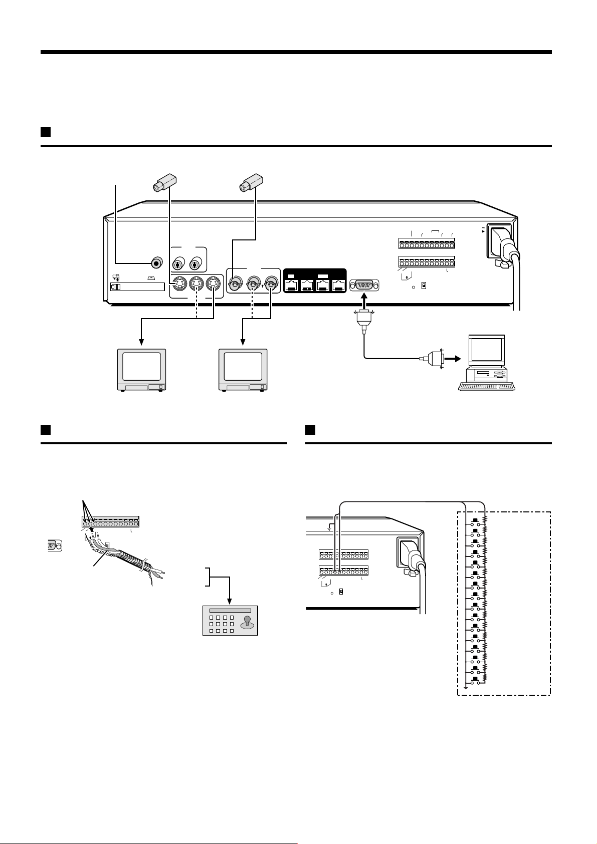
CONNECTIONS
3
Be sure to carefully read the Instruction Manuals for all equipment being connected to the digital video recorder.
If the connections are incorrect, smoke or operating malfunctions may result.
Basic connections
Video camera (sold separately)
Microphone input
AUDIO
AUDIO
MIC
IN
EJECT
PC Card SLOT
S-VIDEO IN
connector
TV monitor
(sold separately)
IN
OUTIN
LOOP OUT
S-VIDEO
VIDEO
IN
LOOP OUT
IN
OUT
TV monitor
(sold separately)
OUT
VIDEO IN
connector
System control connections
Use a twisted-pair cable (sold separately) to connect a system
controller to control terminals A, B and C (ground) of the digital video
recorder. Connect signal A to signal A and signal B to signal B.
Push and insert cables
RS485
OFF
G
C
CLOCK
N
E
I
R
N
O
N
O
C
M
AC IN
N
ADJUST
R
R
T
T
A
L
A
U
U
L
L
O
A
W
U
F
FULLOUTIN
CCNC
NCCC
S
W
O
U
T
ALARM
RESET
ALARM
ALARM
OUT
IN
C
B
REMOTE
RS485
AONC
TERMINATE
ALL
RESET
DIGITAL
SUB OUT
OUT
SUB IN
IN
RS232C
Computer
Connecting a remote control circuit
If a remote control circuit is constructed as shown in the illustration
and connected to the REMOTE control input terminals of the control
connector, the digital video recorder can be operated by remote
control.
2C
AONC
RS485
Twisted-pair cable
B
ALL
RESET
REMOTE
RS485
TERMINATE
OFF
CCNCNCCC
S
W
O
U
T
Ground
To signal B
To signal A
RS-485 connector
System controller (sold separately)
RS485
B
AONC
TERMINATE
ALL
RESET
REMOTE
RS485
OFF
SW OUT
CCNCNCCC
SW: Switch
Note:
The remote control cable should
be no more than 5 m long.
220Ω
SW 1: REC STOP
220Ω
SW 2: PLAY STOP
300Ω
SW 3: PAUSE
360Ω
SW 4: SEARCH
470Ω
SW 5: CHANNEL
680Ω
SW 6: PLAY
820Ω
SW 7: REC
1.2kΩ
SW 8: MENU
1.8kΩ
SW 9 : EXIT/OSD
2.2kΩ
SW 10 : JOG j
3.3kΩ
SW 11 : JOG l
4.7kΩ
SW 12 : SHUTTLE c
7.5kΩ
SW 13 : SHUTTLE d
13kΩ
SW 14 : ZOOM
27kΩ
SW 15 : COPY
68kΩ
SW 16 : TIMER
English
7
Page 9
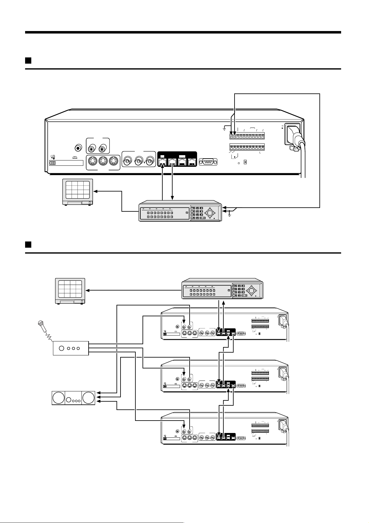
Digital multiplexer connections
Connect to a multiplexer (MPX-CD163P or CD93P) that allows digital connections.
Alarm input
AUDIO
MIC
EJECT
PC Card SLOT
13
IN
2
1
3
6
5
7
10
9
11
14
15
OUTIN
VIDEO
LOOP OUT
IN
IN
LOOP OUT
OUT
S-VIDEO
S-VIDEO
4
8
12
16
OUT
DIGITAL
OUT
SUB IN
IN
SUB OUT
RS232C
✱ Cable (straight-type CAT-5, 3 m or less)
DIGITAL INDIGITAL OUT
TV monitor (sold separately)
Multiplexer (sold separately)
Digital series connections
Up to three digital video recorders can be connected digitally for recording images in series.
Multiplexer (sold separately)
2
1
3
4
6
5
7
8
10
9
11
12
14
13
15
16
TV monitor
(sold separately)
EJECT
PC Card SLOT
AUDIO
MIC
IN
OUTIN
VIDEO
LOOP OUT
IN
OUT
IN
LOOP OUT
OUT
S-VIDEO
IN
G
C
CLOCK
N
E
I
U
ADJUST
T
NCCC
M
N
R
R
T
A
A
U
L
L
O
A
W
U
F
FULLOUTIN
CCNC
S
W
O
U
T
R
N
O
N
O
C
OFF
RS485
C
C
AONC
ALARM
IN
IN
ALARM
RESET
RESET
ALARM
B
ALL
OUT
REMOTE
RS485
TERMINATE
Alarm output
Ground (C)
Digital video recorder (main)
ALARM
CLOCK
ADJUST
RESET
OUT
NON REC
OUT
WARNING
ALARM
ALARM
OUT
IN
FULLOUTIN
C
C
B
NCCC
REMOTE
SW OUT
DIGITAL
SUB OUT
OUT
SUB IN
AONC
RS232C
RS485
TERMINATE
ALL
RS485
RESET
OFF
AC IN
L
AC IN
ALARM
FULL
CCNC
Amplifier
(sold separately)
Amplifier
(sold separately)
AUDIO
MIC
IN
OUTIN
VIDEO
LOOP OUT
IN
OUT
EJECT
PC Card SLOT
IN
LOOP OUT
OUT
S-VIDEO
AUDIO
MIC
IN
OUTIN
EJECT
PC Card SLOT
IN
LOOP OUT
OUT
S-VIDEO
IN
VIDEO
LOOP OUT
IN
OUT
IN
Digital video recorder (sub 1)
ALARM
CLOCK
ADJUST
RESET
OUT
NON REC
OUT
WARNING
ALARM
ALARM
OUT
IN
FULLOUTIN
C
C
NCCC
B
REMOTE
CCNC
SW OUT
DIGITAL
SUB OUT
OUT
SUB IN
AONC
RS232C
RS485
TERMINATE
ALL
RS485
RESET
OFF
Digital video recorder (sub 2)
ALARM
CLOCK
ADJUST
RESET
OUT
NON REC
OUT
WARNING
ALARM
ALARM
OUT
IN
FULLOUTIN
C
C
B
NCCC
REMOTE
CCNC
SW OUT
DIGITAL
SUB OUT
OUT
SUB IN
AONC
RS232C
RS485
TERMINATE
ALL
RS485
RESET
OFF
AC IN
ALARM
FULL
AC IN
ALARM
FULL
Note: When digital video recorders are connected digitally in series, the digital input and output terminals can be used to transmit video signals,
control signals and switching signals. However audio signals cannot be transmitted in the same way, so if audio signals also need to be
recorded, connect the audio input terminals via an amplifier as shown in the connection diagram.
8
English
Page 10
BUILT-IN HARD DISK
Normal recording area
Alarm
1%
80%
19%
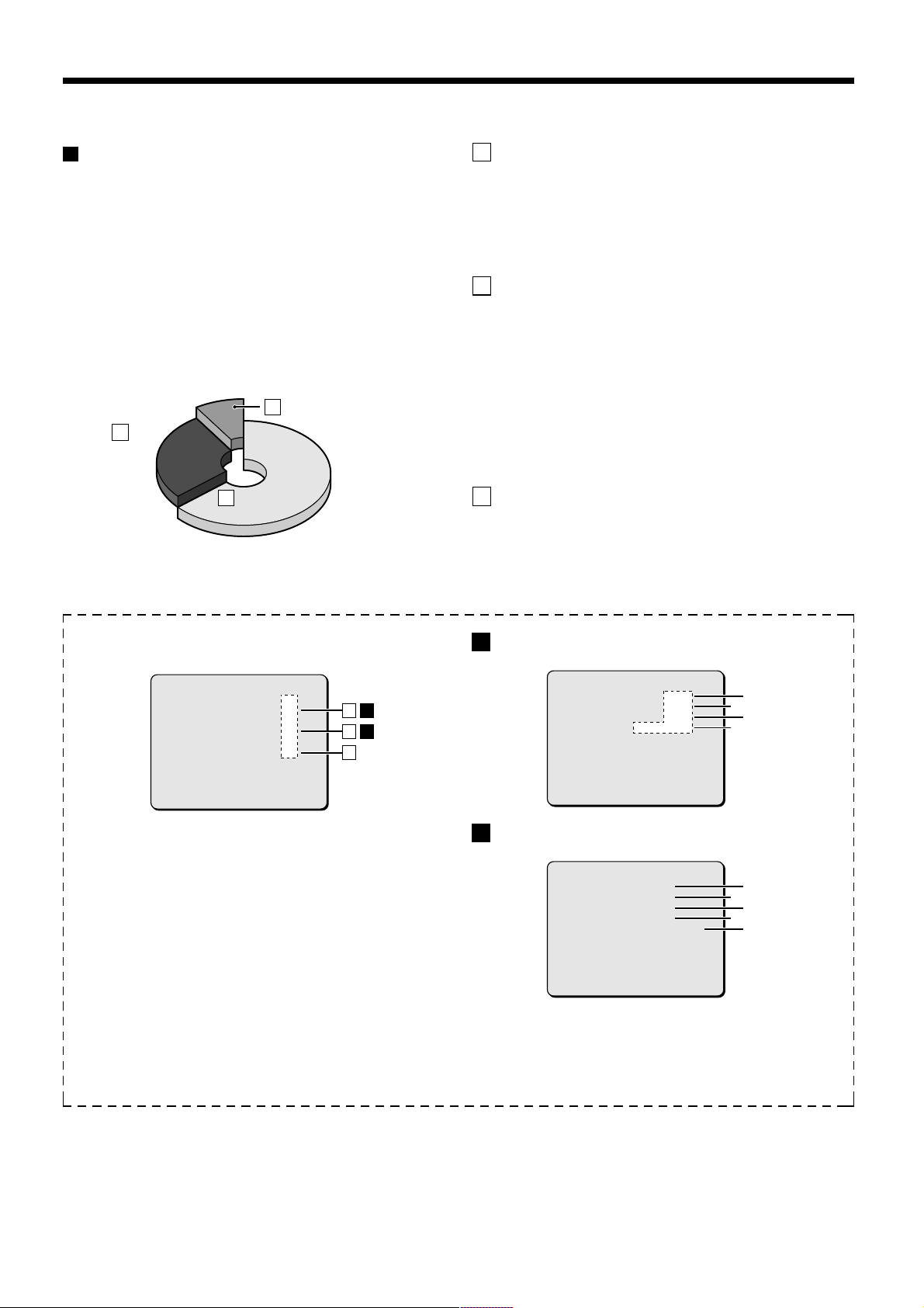
Hard disk
Recording areas
The recording areas on the hard disk (normal recording area: 80%,
alarm recording area: 19%, archive area: 1%) are established
automatically when the power for the digital video recorder is turned
on. Images are recorded in the normal recording area when the
REC/STOP button is pressed, and they are recorded in the alarm
recording area when an alarm occurs. This is called the default
condition, and the following detailed settings can be confirmed in the
sections on “RECORDING IMAGES IN THE NORMAL RECORDING
AREA” and “RECORDING IMAGES IN THE ALARM RECORDING
AREA” which are explained later. Furthermore, settings such as the
recording areas and picture quality can be changed using the menu
screens.
Archive areaC
80%
80%
Normal recording areaA
Normal recording area
Alarm
Alarm
B
recording
recording
area
area
1%
1%
19%
19%
Hard disk recording areas
A Normal recording area
When the REC/STOP button is pressed while monitoring is in
•
progress, images are recorded in the normal recording area.
When start and end times are entered for each day of the week
•
and are then enabled, timer recording is automatically carried out
in the normal recording area between the times that have been
set.
B Alarm recording area
ALARM REC MODE SET menu settings are required.
Alarm recording is enabled when ALARM RECORDING is set.
•
When a suspicious person is detected by the switch or motion
sensor that is connected to the alarm input terminal, an alarm is
recorded in the alarm recording area.
Pre-alarm recording is enabled when PRE-ALARM RECORDING
•
is set. Pre-alarm recording repeatedly records the same images
as for normal recording in the alarm recording area, and
overwrites these images after the set time interval, until an alarm
is detected. When pre-alarm recording is set, the image
immediately before an alarm occurred can be recorded.
C Archive area
This is the area for copying important images from the normal
recording area and the alarm recording area. The size of the archive
area can be set to a maximum of 12 GB (15% of total capacity when
using an 80-GB hard disk) by changing the size of the normal
recording area or the alarm recording area.
Menu screen (initial setting)
This can be displayed by pressing the MENU button.
<RECORDING AREA SET>
TOTAL CAPACITY : 80GB
NORMAL RECORDING AREA : 80 %
AREA FULL RESET ->
ALARM RECORDING AREA : 19 %
AREA FULL RESET ->
ARCHIVE AREA : 1 %
AREA FULL RESET ->
CAUTION : WHEN THE AREA SETTING IS CHANGED.
THE WHOLE AREA WILL BE INITIALIZED !
1
Picture quality: ENHANCED
Picture quality can be selected from five options.
The recording speed changes in accordance with the picture
quality selected.
2
Recording method: Can be set to FRAME or FIELD.
The recording speed changes in accordance with the method
selected.
3
Audio recording: Can be set to ON or OFF.
4
Recording speed: Shows the recording interval and the
recording time.
Refer to the recording speed table for further details.
5
Alarm recording setting: Can be set to ON or OFF.
When alarm recordings are to be made, select a setting such
as MODE1 for the OFF setting. The recording speed and
alarm duration will be displayed
ABA
B
C
A
Setting screen for normal recording area picture quality,
recording speed, etc.
<NORMAL REC MODE SET>
PICTURE QUALITY : ENHANCED
FRAME/FIELD RECORDING : FIELD
AUDIO RECORDING : OFF
REC CYCLE : 0.12SEC ( 65H)
B
Setting screen for alarm recording area picture quality,
recording speed, etc.
<ALARM REC MODE SET>
PICTURE QUALITY : ENHANCED
FRAME/FIELD RECORDING : FIELD
AUDIO RECORDING : OFF
ALARM RECORDING : OFF
REC CYCLE : 0.12SEC. DURATION: 1SEC
PRE-ALARM RECORDING :
REC CYCLE :
=> (55682 ALARMS CAN BE RECORDED)
ALARM TRIGGER : ALARM
MOTION SENSOR ->
¤¤¤
¤¤¤
SEC. DURATION:
¤¤¤
2
4
2
5
1
3
1
3
4
English
9
Page 11
BUILT-IN HARD DISK
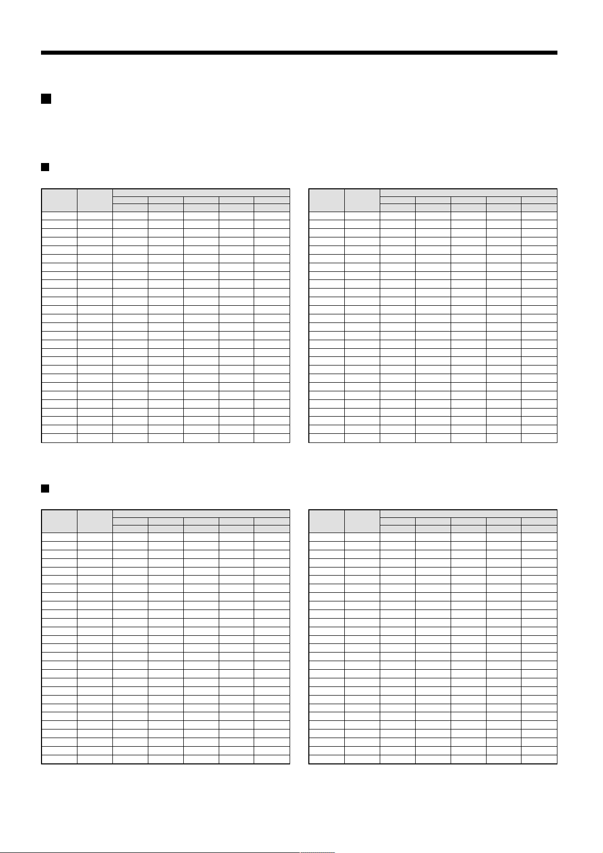
Recording speed tables
These recording speed tables show the recording times for various picture quality and frame/field settings when recording in the normal
recording area of the hard disk (80 GB). They do not include audio recording settings.
The setting times for the normal recording area and the alarm recording area represent the picture quality values given in the recording speed
tables, multiplied by the percentages for the normal recording area and alarm recording area that have been set using the recording area setting
menu commands.
When recording with an 80-GB hard disk at 100% capacity
Field recording
Recording
(field/sec)
50.00 0.02 25H 18H 13H 9H 7H
25.00 0.04 51H 36H 27H 19H 14H
16.67 0.06 76H 54H 40H 29H 22H
12.50 0.08 102H 72H 54H 39H 29H
Recording
Rate
Cycle (SEC)
8.33 0.12 153H 108H 81H 59H 44H
6.25 0.16 204H 144H 108H 78H 59H
5.00 0.20 255H 180H 135H 98H 74H
4.17 0.24 306H 217H 162H 118H 89H
3.57 0.28 357H 253H 189H 138H 104H
3.13 0.32 408H 289H 217H 157H 119H
2.78 0.36 459H 325H 244H 177H 134H
2.50 0.40 510H 361H 271H 197H 149H
2.27 0.44 561H 397H 298H 217H 164H
1.92 0.52 663H 470H 352H 256H 194H
1.67 0.60 765H 542H 406H 295H 224H
1.47 0.68 868H 614H 461H 335H 254H
1.32 0.76 970H 687H 515H 374H 284H
1.19 0.84 1072H 759H 569H 414H 314H
1.09 0.92 1174H 831H 623H 453H 344H
1.00 1 1276H 904H 678H 493H 374H
0.50 2 2553H 1808H 1356H 986H 748H
0.33 3 3829H 2712H 2034H 1479H 1122H
0.25 4 5106H 3616H 2712H 1972H 1496H
0.20 5 6382H 4521H 3390H 2466H 1870H
0.10 10 12765H 9042H 6781H 4932H 3741H
0.05 20 25531H 18084H 13563H 9864H 7483H
0.03 30 38296H 27126H 20345H 14796H 11224H
BASIC NORMAL ENHANCED FINE SUPER FINE
15 kB 22 kB 30 kB 42 kB 56 kB
PICTURE QUALITY
The tables below are recording speed tables provided for reference if the total capacity of the hard disk has been increased to 160 GB. Contact
the place of purchase for details on increasing the capacity of the hard disk.
Frame recording
Recording
(frame/sec)
25.00 0.04 25H 18H 13H 9H 7H
12.50 0.08 51H 36H 27H 19H 14H
Recording
Rate
Cycle (SEC)
8.33 0.12 76H 54H 40H 29H 22H
6.25 0.16 102H 72H 54H 39H 29H
4.17 0.24 153H 108H 81H 59H 44H
3.13 0.32 204H 144H 108H 78H 59H
2.50 0.40 255H 180H 135H 98H 74H
2.08 0.48 306H 217H 162H 118H 89H
1.79 0.56 357H 253H 189H 138H 104H
1.56 0.64 408H 289H 217H 157H 119H
1.39 0.72 459H 325H 244H 177H 134H
1.25 0.80 510H 361H 271H 197H 149H
1.14 0.88 561H 397H 298H 217H 164H
0.96 1.04 663H 470H 352H 256H 194H
0.83 1.20 765H 542H 406H 295H 224H
0.74 1.36 868H 614H 461H 335H 254H
0.66 1.52 970H 687H 515H 374H 284H
0.60 1.68 1072H 759H 569H 414H 314H
0.54 1.84 1174H 831H 623H 453H 344H
0.50 2 1276H 904H 678H 493H 374H
0.25 4 2553H 1808H 1356H 986H 748H
0.17 6 3829H 2712H 2034H 1479H 1122H
0.13 8 5106H 3616H 2712H 1972H 1496H
0.10 10 6382H 4521H 3390H 2466H 1870H
0.05 20 12765H 9042H 6781H 4932H 3741H
0.03 40 25531H 18084H 13563H 9864H 7483H
0.02 60 38296H 27126H 20345H 14796H 11224H
BASIC NORMAL ENHANCED FINE SUPER FINE
15 kB 22 kB 30 kB 42 kB 56 kB
PICTURE QUALITY
When recording with a 160-GB hard disk at 100% capacity
Field recording
Recording
(field/sec)
50.00 0.02 51H 36H 27H 19H 14H
25.00 0.04 102H 72H 54H 39H 29H
16.67 0.06 153H 108H 81H 59H 44H
12.50 0.08 204H 144H 108H 78H 59H
Recording
Rate
Cycle (SEC)
8.33 0.12 306H 217H 162H 118H 89H
6.25 0.16 408H 289H 217H 157H 119H
5.00 0.20 510H 361H 271H 197H 149H
4.17 0.24 612H 434H 325H 236H 179H
3.57 0.28 714H 506H 379H 276H 209H
3.13 0.32 816H 578H 434H 315H 239H
2.78 0.36 919H 651H 488H 355H 269H
2.50 0.40 1021H 723H 542H 394H 299H
2.27 0.44 1123H 795H 596H 434H 329H
1.92 0.52 1327H 940H 705H 512H 389H
1.67 0.60 1531H 1085H 813H 591H 448H
1.47 0.68 1736H 1229H 922H 670H 508H
1.32 0.76 1940H 1374H 1030H 749H 568H
1.19 0.84 2144H 1519H 1139H 828H 628H
1.09 0.92 2348H 1663H 1247H 907H 688H
1.00 1 2553H 1808H 1356H 986H 748H
0.50 2 5106H 3616H 2712H 1972H 1496H
0.33 3 7659H 5425H 4069H 2959H 2244H
0.25 4 10212H 7233H 5425H 3945H 2993H
0.20 5 12765H 9042H 6781H 4932H 3741H
0.10 10 25531H 18084H 13563H 9864H 7483H
0.05 20 51062H 36168H 27126H 19728H 14966H
0.03 30 76593H 54253H 40690H 29592H 22449H
BASIC NORMAL ENHANCED FINE SUPER FINE
15 kB 22 kB 30 kB 42 kB 56 kB
Reference: 24H = 1 day, 168H = 1 week, 720H = 1 month, 8760H = 1 year
PICTURE QUALITY
Frame recording
Recording
(frame/sec)
25.00 0.04 51H 36H 27H 19H 14H
12.50 0.08 102H 72H 54H 39H 29H
Recording
Rate
Cycle (SEC)
8.33 0.12 153H 108H 81H 59H 44H
6.25 0.16 204H 144H 108H 78H 59H
4.17 0.24 306H 217H 162H 118H 89H
3.13 0.32 408H 289H 217H 157H 119H
2.50 0.40 510H 361H 271H 197H 149H
2.08 0.48 612H 434H 325H 236H 179H
1.79 0.56 714H 506H 379H 276H 209H
1.56 0.64 816H 578H 434H 315H 239H
1.39 0.72 919H 651H 488H 355H 269H
1.25 0.80 1021H 723H 542H 394H 299H
1.14 0.88 1123H 795H 596H 434H 329H
0.96 1.04 1327H 940H 705H 512H 389H
0.83 1.20 1531H 1085H 813H 591H 448H
0.74 1.36 1736H 1229H 922H 670H 508H
0.66 1.52 1940H 1374H 1030H 749H 568H
0.60 1.68 2144H 1519H 1139H 828H 628H
0.54 1.84 2348H 1663H 1247H 907H 688H
0.50 2 2553H 1808H 1356H 986H 748H
0.25 4 5106H 3616H 2712H 1972H 1496H
0.17 6 7659H 5425H 4069H 2959H 2244H
0.13 8 10212H 7233H 5425H 3945H 2993H
0.10 10 12765H 9042H 6781H 4932H 3741H
0.05 20 25531H 18084H 13563H 9864H 7483H
0.03 40 51062H 36168H 27126H 19728H 14966H
0.02 60 76593H 54253H 40690H 29592H 22449H
BASIC NORMAL ENHANCED FINE SUPER FINE
15 kB 22 kB 30 kB 42 kB 56 kB
PICTURE QUALITY
10
English
Page 12
BUILT-IN HARD DISK
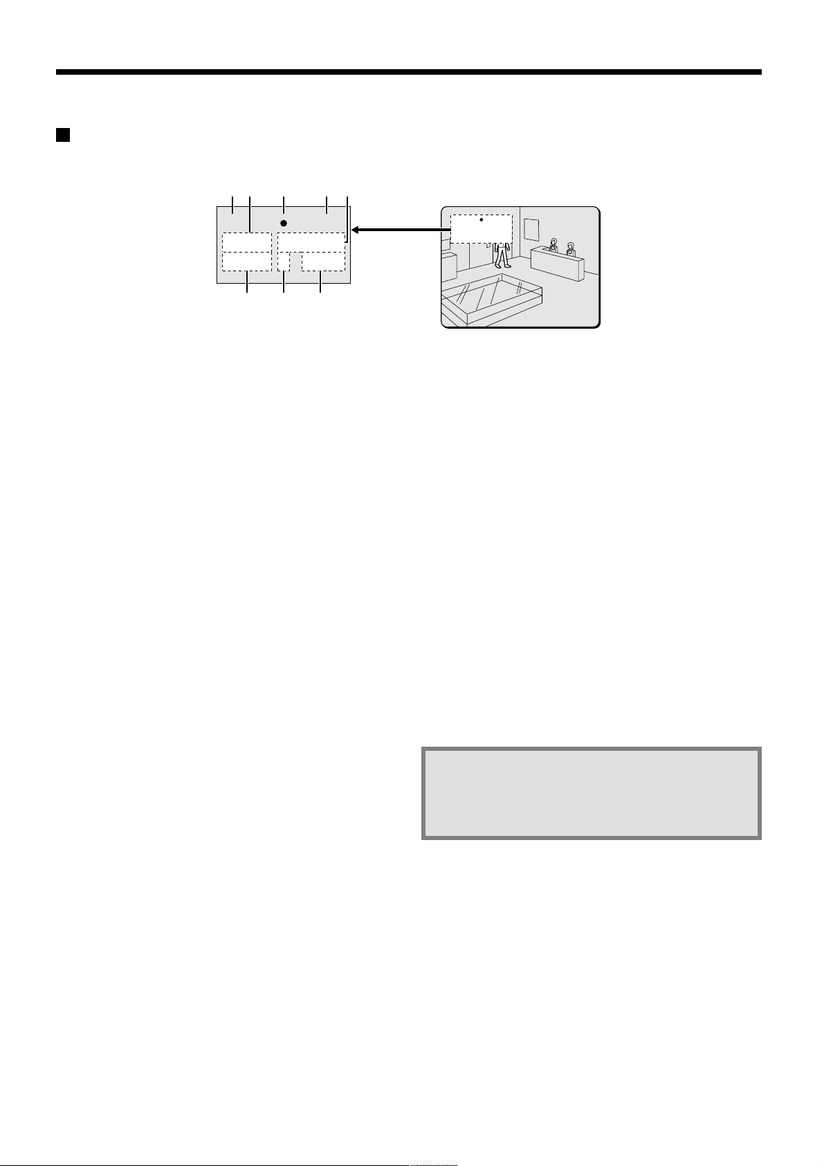
Operating display
When the power for the digital video recorder is turned on, the operating display appears in the upper-left corner of the monitor screen. This
operating display shows information which is essential for operation, such as the date, time, picture quality and recording speed.
1623 45
4CH 100%
01-01-01 ALARM 0000
00:00:00 EN 0.12SEC
78
Camera number display
1
Connect the digital video recorder to a multiplexer that is capable
of decoding Sanyo’s channel information (camera number) and
press the CHANNEL button. The number of the specified camera
appear in the display during playback.
Date display
2
When the digital video recorder is first turned on, the date
appears as 01-01-01 (day, month, year). Make sure that you use
the menus to set the correct date.
Operating symbol display
3
These symbols appear during recording and playback.
a : Recording e : Fast forward
c : Playback f : Rewind
d : Reverse playback h : Stopped
hc : Slow playback dh : Slow reverse playback
Note: If recording and playback are being carried out at the same
time, the playback symbol (c) appears.
Amount of recording area remaining
4
If overwriting has been disabled (OVERWRITE: OFF) in the
normal recording area or alarm recording area, the amount of
space remaining appears as a percentage. You can change the
amount of recording area remaining using the RECORDING
CONDITIONS SET menu item. (See page 45.)
Alarm display and alarm number display
5
When an alarm setting is made using the ALARM REC MODE
SET menu item, The following display appears in the alarm
display.
However, the PRE display appears when pre-alarm recording has
been set. When an alarm occurs, the PRE is replaced by ALARM
and the number of alarms also appears. The alarm display shows
the cumulative number of alarms.
•
If ALARM RECORDING is set: ALARM appears.
ALARM flashes while an alarm is being recorded.
•
If PRE-ALARM RECORDING is set: PRE appears.
•
When playing images from the archive area: ARCHIV appears.
01-01-01 ALARM 0000
00:00:00 EN 0.12SEC
Time display
6
When the digital video recorder is first turned on, the time
appears as 00:00:00, and the time starts counting after the date
has been set. The digital video recorder uses the date and time to
control recording and playback, so if the date and time have not
been set, the correct images cannot be retrieved. Make sure that
you use the menus to set the correct time.
Picture quality display
7
This shows the picture quality for images that are recorded on the
hard disk. The default setting is EN (Enhanced). The display
changes when the picture quality is changed using the NORMAL
REC MODE SET menu item.
•
BA: Basic
•
NO: Normal
•
EN: Enhanced
•
FI: Fine
•
SF: Super Fine
Recording speed display
8
This displays the recording speed for images that are recorded
on the hard disk. The default setting is 0.12 SEC (during field
recording). The display changes when the picture quality and
recording method are changed using the NORMAL REC MODE
SET menu item.
Note: During recording with this unit, playing back,
copying and transferring pictures is possible.
However, because of the recording priority the
response of the other operations becomes slower.
English
11
Page 13
RECORDING IMAGES IN THE
NORMAL RECORDING AREA
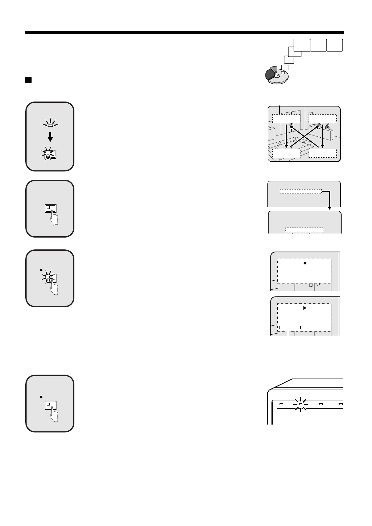
Normal recording
Images can be recorded in the normal recording area while they are being monitored.
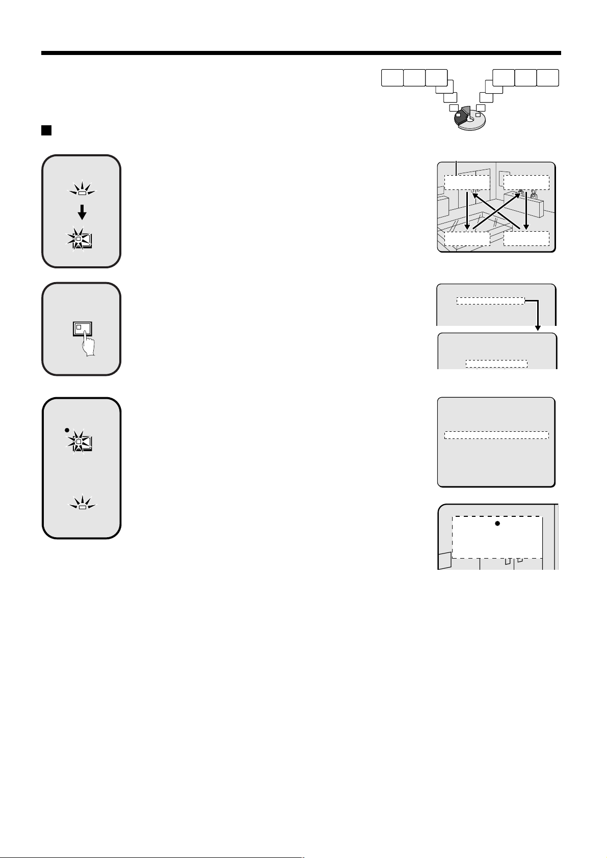
Insert the power cord into a wall outlet and turn on the
1
POWER
EXIT/OSD
2
MENU
power.
The POWER indicator illuminates, and after approximately 15 seconds, the
EXIT/OSD indicator illuminates. The camera images appear on the monitor,
and the operating display appears in the top-left corner of the screen.
Note: The operating display can be moved or switched off by pressing the
EXIT/OSD button repeatedly.
See page 11 for details of the operating display.
Setting the time
Press the MENU button to display the LANGUAGE/CLOCK SET menu, and
set the date and time. After the setting has been made, press the EXIT/OSD
button, the date and time appear in the operating display. (See page 40.)
Monitored images
are recorded.
Operating display
01-01-01
00:00:00 EN 0.12SEC
<MAIN MENU 1>
1.LANGUAGE/CLOCK SET ->
2.VIDEO INPUT SET ->
3.RECORDING AREA SET ->
4.RECORDING CONDITIONS SET ->
<LANGUAGE/LANGUE/SPRACHE/IDIOMA>
ENGLISH
<CLOCK SET>
01-01-2001 MON 00:00:00
3
4
REC/STOP
REC/STOP
Press the REC/STOP button.
“a” appears in the operating display and the images being monitored are
recorded in the normal recording area. Recording onto the hard disk
proceeds automatically (default setting) according to the following settings.
The settings can be changed between long-period recording and high-quality
recording in five steps. (See page 47.)
Hard disk recording areas:
•
Normal recording area: 80%
Alarm recording area: 19%
Archive area: 1%
Picture quality: EN (Enhanced)
•
Recording method: Field
•
Recording speed: 0.12 seconds (65H)
•
Note: Playback is possible during recording. When the PLAY/STOP button is
pressed during recording, “c” appears in the operating display and
images are played back from the point where recording began. (See
page 19.)
Press and hold the REC/STOP button for 3 seconds or
more.
The “a” in the operating display disappears and recording stops.
Note: When the remaining area in the normal recording area drops below the
set amount, the FULL indicator on the front panel flashes. If recording
continues under these conditions, the recording area becomes full and
recording stops. In the RECORDING AREA SET settings, carry out the
AREA FULL RESET operation for the normal recording area.
Recording will then be possible from the beginning again. (See page
44.)
26-10-01
10:48:38 EN 0.12SEC
26-10-01
11:02:28 EN 0.12SEC
Recording start time
POWER FULL
ALARM FULL
LOC
12
English
Page 14
RECORDING IMAGES IN THE NORMAL RECORDING AREA
Timer recording
The monitored images can be recorded automatically by setting start and end times for each day of the week.
1
2
POWER
EXIT/OSD
MENU
Insert the power cord into a wall outlet and turn on the
power.
The POWER indicator illuminates, and after approximately 15 seconds, the
EXIT/OSD indicator illuminates. The camera images appear on the monitor,
and the operating display appears in the top-left corner of the screen.
Note: The operating display can be moved or switched off by pressing the
EXIT/OSD button repeatedly.
See page 11 for details of the operating display.
1 Setting the time
Press the MENU button to display the LANGUAGE/CLOCK SET menu, and
set the date and time. After the setting has been made, press the EXIT/OSD
button, the date and time appear in the operating display. (See page 40.)
2 Set the timer.
Press the MENU button to display the TIMER SET menu, and then set the
start and end times for timer recording. (See page 48.)
Then press the EXIT/OSD button.
Operating display
01-01-01
00:00:00 EN 0.12SEC
<MAIN MENU 1>
1.LANGUAGE/CLOCK SET ->
2.VIDEO INPUT SET ->
3.RECORDING AREA SET ->
4.RECORDING CONDITIONS SET ->
<LANGUAGE/LANGUE/SPRACHE/IDIOMA>
ENGLISH
<CLOCK SET>
01-01-2001 MON 00:00:00
<MAIN MENU 1>
1.LANGUAGE/CLOCK SET ->
2.VIDEO INPUT SET ->
3.RECORDING AREA SET ->
4.RECORDING CONDITIONS SET ->
5.NORMAL REC MODE SET ->
6.TIMER SET ->
3
TIMER
Press the TIMER button.
The TIMER indicator illuminates and the digital video recorder switches to
timer recording standby mode.
Note:
If SET in the TIMER SET menu is not set to “ON”, or if the timer settings
•
are not made correctly, an alarm will sound when the TIMER button is
pressed.
The TIMER indicator illuminates when the timer setting has been made
•
correctly.
When the timer setting time is reached, the TIMER indicator and the REC
•
indicator illuminate and timer recording starts.
If you press the TIMER button during timer recording, the TIMER indicator
•
and the REC indicator switch off and timer recording stops.
<TIMER SET>
WEEK START STOP REC CYCLE SET
SUN --:-- --:-- 0.12SEC ( 65H) OFF
MON --:-- --:-- 0.12SEC ( 65H) OFF
TUE --:-- --:-- 0.12SEC ( 65H) OFF
WED --:-- --:-- 0.12SEC ( 65H) OFF
10-05-01
17:30:25 EN 0.12SEC
English
13
Page 15
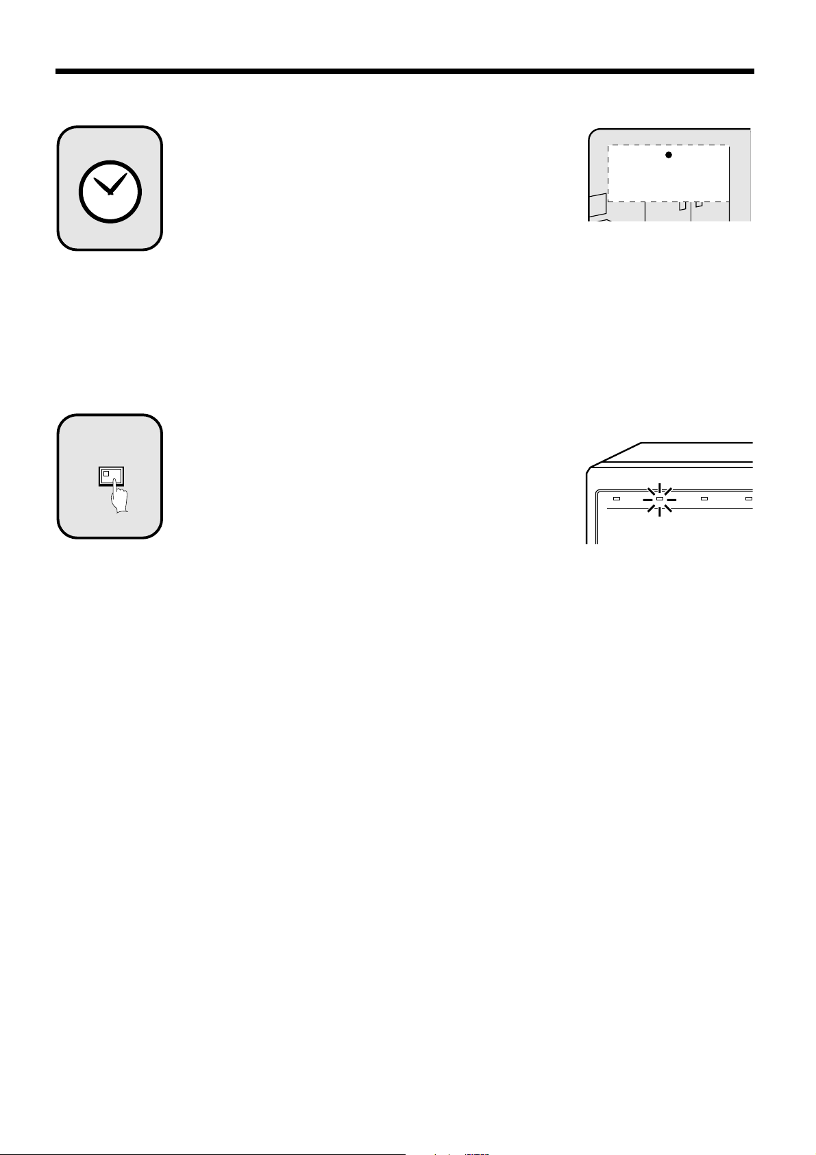
4
5
TIMER
Timer recording starts when the timer setting time is
reached.
“a” appears in the operating display and the images being monitored are
recorded in the normal recording area. Recording onto the hard disk
proceeds automatically (default setting) according to the following settings.
The settings can be changed between long-period recording and high-quality
recording in five steps. (See page 47.)
Hard disk recording areas:
•
Normal recording area: 80%
Alarm recording area: 19%
Archive area: 1%
Picture quality: EN (Enhanced)
•
Recording method: Field
•
Recording speed: 0.12 seconds (65H)
•
Note: Playback is possible during recording. When the PLAY/STOP button is
pressed during recording, c appears in the operating display and
images are played back from the point where recording began. (See
page 19.)
Timer recording stops when the set end time is reached.
The TIMER indicator swithes off and the recording symbol (a) disappears
from the operating display and recording stops.
Note:
Press the TIMER button to stop timer recording. Timer recording then
•
stops.
When the remaining area in the normal recording area drops below the
•
set amount, the FULL indicator on the front panel flashes. If recording
continues under these conditions, the recording area becomes full and
recording stops. In the RECORDING AREA SET settings, carry out the
AREA FULL RESET operation for the normal recording area.
Recording will then be possible from the beginning again. (See page 44.)
10-05-01
19:30:00 EN 0.12SEC
POWER FULL
ALARM FULL
LOC
14
English
Page 16
RECORDING IMAGES IN THE
ALARM RECORDING AREA
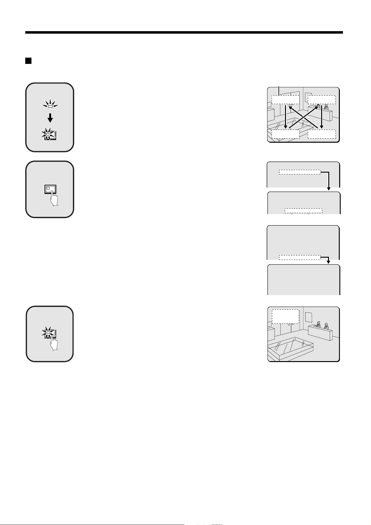
Alarm recording
Alarm images are
recorded
1
2
POWER
EXIT/OSD
MENU
Insert the power cord into a wall outlet and turn on the
power.
The POWER indicator illuminates, and after approximately 15 seconds, the
EXIT/OSD indicator illuminates. The camera images appear on the monitor,
and the operating display appears in the top-left corner of the screen.
Note: The operating display can be moved or switched off by pressing the
EXIT/OSD button repeatedly.
See page 11 for details of the operating display.
1 Setting the time
Press the MENU button to display the LANGUAGE/CLOCK SET menu, and
set the date and time. After the setting has been made, press the EXIT/OSD
button, the date and time appear in the operating display. (See page 40.)
2 Set alarm recording.
Press the MENU button to display the ALARM REC MODE SET menu
•
from the MAIN MENU screen. Then change the ALARM RECORDING
setting to the desired alarm recording setting (MODE1, 2, 3 or 4) and
change the ALARM TRIGGER setting. (See page 52 – 54.)
Press the MENU button, to display the BUZZER SET menu from the
•
MAIN MENU 2 screen, and change the ALARM setting to “ON”.
(See page 60.)
Press the EXIT/OSD button to return to the normal screen.
•
Operating display
01-01-01
00:00:00 EN 0.12SEC
<MAIN MENU 1>
1.LANGUAGE/CLOCK SET ->
2.VIDEO INPUT SET ->
3.RECORDING AREA SET ->
4.RECORDING CONDITIONS SET ->
<LANGUAGE/LANGUE/SPRACHE/IDIOMA>
ENGLISH
<CLOCK SET>
01-01-2001 MON 00:00:00
<ALARM REC MODE SET>
PICTURE QUALITY : ENHANCED
FRAME/FIELD RECORDING : FIELD
AUDIO RECORDING : OFF
ALARM RECORDING : MODE1
REC CYCLE : 0.12SEC. DURATION: 1SEC
PRE-ALARM RECORDING : ¤¤¤
REC CYCLE : ¤¤¤ SEC. DURATION: ¤¤¤
=> (55682 ALARMS CAN BE RECORDED)
ALARM TRIGGER : ALARM
MOTION SENSOR ->
3
4
ALARM
Suspicious person detection
When an alarm occurs, “ALARM” appears in the operating display, the
ALARM indicator flashes and alarm recording (a symbol) starts. Alarm
images are recorded in the alarm recording area. Furthermore, the number of
alarms in the operating display is increased by one each time an alarm
occurs.
Note: Normal recording and timer recording stop when an alarm occurs
during normal recording or timer recording.
Ending alarm recording
Recording ends after the end of the alarm duration period (default setting: 1
sec). The “a” and ALARM displays stop flashing and recording stops.
Note: When the remaining area in the alarm recording area reaches 1%, the
ALARM FULL indicator on the front panel flashes. If recording is
continued under these conditions, the recording area is filled and the
recording stops. In the RECORDING AREA SET settings, carry out the
AREA FULL RESET operation for the alarm recording area.
Overwriting will be canceled and recording will be possible from the
beginning again. (See page 44.)
10-05-01 ALARM 0001
18:10:25 EN 0.12SEC
The number of
alarms is counted.
POWER FULL
ALARM FULL
LOC
English
15
Page 17
RECORDING IMAGES IN THE ALARM
RECORDING AREA
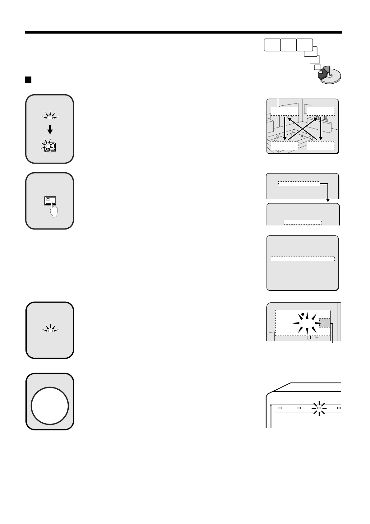
Pre-alarm recording
Insert the power cord into a wall outlet and turn on the
1
POWER
EXIT/OSD
2
MENU
power.
The POWER indicator illuminates, and after approximately 15 seconds, the
EXIT/OSD indicator illuminates. The camera images appear on the monitor,
and the operating display appears in the top-left corner of the screen.
Note: The operating display can be moved or switched off by pressing the
EXIT/OSD button repeatedly.
See page 11 for details of the operating display.
Setting the time
Press the MENU button to display the LANGUAGE/CLOCK SET menu, and
set the date and time. After the setting has been made, press the EXIT/OSD
button, the date and time appear in the operating display. (See page 40.)
Pre-alarm images
are recorded
Monitored images
are recorded
Operating display
01-01-01
00:00:00 EN 0.12SEC
<MAIN MENU 1>
1.LANGUAGE/CLOCK SET ->
2.VIDEO INPUT SET ->
3.RECORDING AREA SET ->
4.RECORDING CONDITIONS SET ->
<LANGUAGE/LANGUE/SPRACHE/IDIOMA>
ENGLISH
<CLOCK SET>
01-01-2001 MON 00:00:00
3
REC/STOP
ALARM
Set pre-alarm recording.
Press the MENU button to display the ALARM REC MODE SET menu. Set
ALARM RECORDING to the desired alarm recording setting (example:
MODE1). The *** setting for PRE-ALARM RECORDING will be set to
“OFF”, so change it to “ON”. (See page 54.)
Press the EXIT/OSD button to return to the normal screen. “PRE” appears in
the operating display, the ALARM indicator illuminates and pre-alarm
recording starts (the a mark does not appear).
The same monitored image as in the normal recording area is recorded
repeatedly in the alarm recording area.
Recording onto the hard disk proceeds automatically (default setting)
according to the following settings. The settings can be changed between
long-period recording and high-quality recording in five steps. (See page 47.)
Hard disk recording areas:
•
Normal recording area: 80%
Alarm recording area: 19%
Archive area: 1%
Picture quality: EN (Enhanced)
•
Recording method: Field
•
Recording speed: 0.12 seconds (65H)
•
<ALARM REC MODE SET>
PICTURE QUALITY : ENHANCED
FRAME/FIELD RECORDING : FIELD
AUDIO RECORDING : OFF
ALARM RECORDING : MODE1
REC CYCLE : 0.12SEC. DURATION: 1SEC
PRE-ALARM RECORDING : ¤¤¤
REC CYCLE : ¤¤¤ SEC. DURATION: ¤¤¤
=> (55682 ALARMS CAN BE RECORDED)
ALARM TRIGGER : ALARM
MOTION SENSOR ->
10-05-01 PRE 0000
18:10:25 EN 0.12SEC
16
English
Page 18

RECORDING IMAGES IN THE ALARM RECORDING AREA
When an alarm is received, pre-alarm recording stops
4
ALARM
automatically and the alarm images are recorded.
The “PRE” disappears from the operating display, “ALARM” flashes and the
ALARM indicator flashes.
Note: When the remaining area in the alarm recording area reaches 1%, the
ALARM FULL indicator on the front panel flashes. If recording is
continued under these conditions, the recording area is filled and the
recording stops.
In the RECORDING AREA SET settings, carry out the AREA FULL
RESET operation for the normal recording area.
Recording will then be possible from the beginning again. (See page
44.)
10-06-01 ALARM 0000
09:30:15 EN 0.12SEC
POWER FULL
ALARM FULL
LOC
English
17
Page 19
PLAYING BACK IMAGES RECORDED IN
THE NORMAL RECORDING AREA
The digital video recorder can play back recorded images in the normal recording area (normal recording, timer recording).
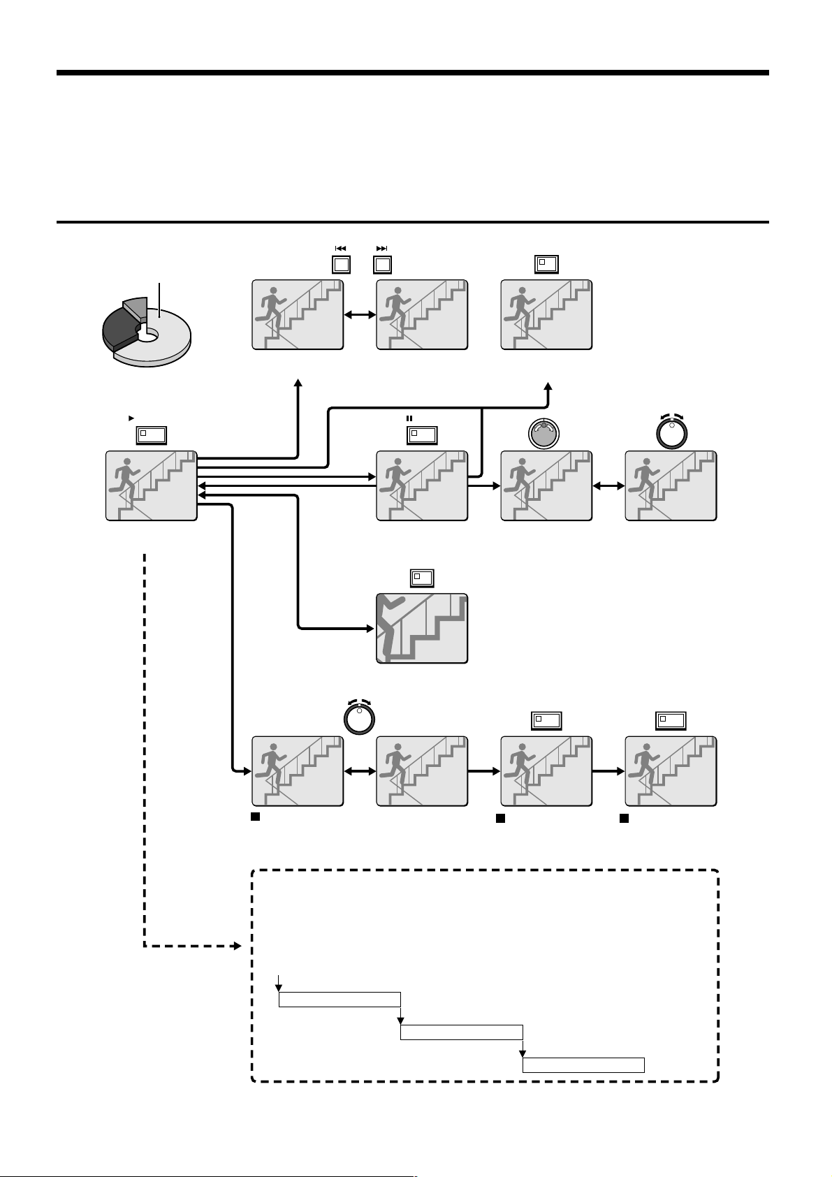
Playback operations
Normal recording area
PLAY/STOP
b Playback
(See page 19.)
ALARM
b Skipping to the previous or next alarm
(See page 24.)
STILL
b Still image
(See page 21.)
ZOOM
SEARCH
FRAME/FIELD
b Switching between frame and field
(See page 22.)
b Frame advance
(forward/reverse)
(See page 21.)
b Slow playback
(See page 19.)
b Zooming images (See page 20.)
SHUTTLE HOLD SHUTTLE HOLD
Fast forward/fast rewind playback
(See page 19.)
Locking speed for
fast forward/rewind
playback
(See page 19.)
Normal playback
• When playing back recordings for the first time:
The recorded images will be played back from the beginning.
• When playing back for the second or subsequent time:
Playback will start from the point where the last playback session ended.
(Starting point for
first playback)
Ending point
(Starting point for
second playback)
Ending point
(Starting point for
third playback)
Releasing speed
lock
Ending point
18
English
Page 20
PLAYING BACK IMAGES RECORDED IN THE NORMAL
RECORDING AREA
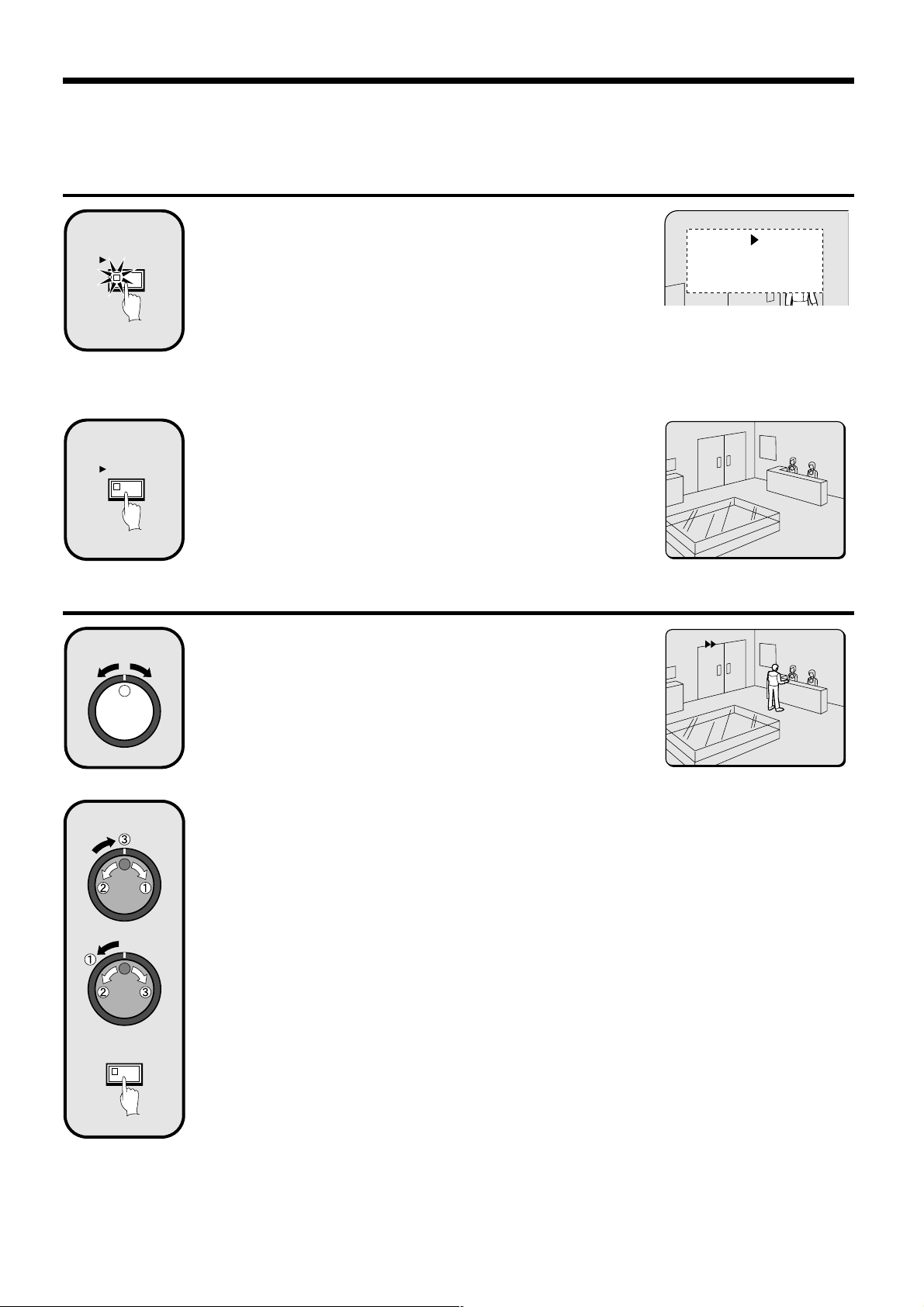
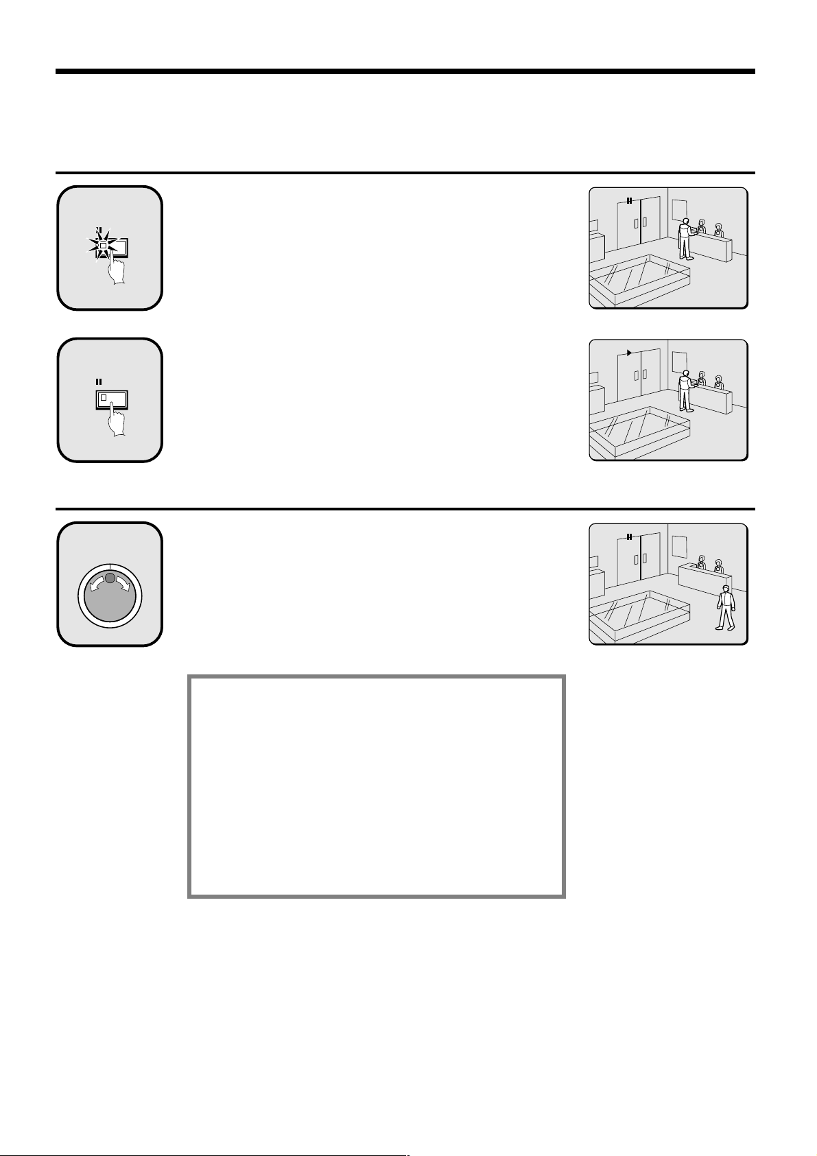
Playback
Press the PLAY/STOP button.
1
PLAY/STOP
2
PLAY/STOP
c appears in the operating display and the images recorded in the normal
recording area are played back.
Note:
Image playback starts from the point (time) that the recording started.
•
If there is no starting position, or if a reset has been made, the oldest
recorded image is played back.
When playback is finished, playback mode is automatically paused.
•
The pause (h) symbol appears in the operating display and the STILL
indicator illuminates.
If playback has been carried out at least once, playback will start from the
•
position where the last playback session ended.
Press the PLAY/STOP button again.
Playback stops.
Note: If playback is started just as recording is being carried out, recording
will have priority, so that the playback images may be paused
momentarily.
26-10-01
11:02:50 EN 0.12SEC
20-11-01
04:00:00 EN 0.12SEC
Fast forward/rewind playback
Turn the shuttle dial clockwise (or counterclockwise)
1
2
SHUTTLE HOLD
during playback.
When the shuttle dial is turned clockwise, e appears in the operating
display and fast forward playback starts. If it is turned counterclockwise, f
appears in the operating display and rewind playback starts.
When you release the shuttle dial, normal playback resumes.
Changing the playback speed
(Fast forward/slow playback)
1 Turn the jog dial clockwise.
Fast forward playback starts and e appears in the operating display.
2 Turn the jog dial counterclockwise.
Slow playback starts and hc appears in the operating display.
3 Return to normal playback.
Turn the jog dial clockwise. c appears in the operating display.
(Rewind/slow playback)
1 Turn the shuttle dial counterclockwise (fix at rewind).
d will be displayed, so press the SHUTTLE HOLD button. The SHUTTLE HOLD indicator will illuminate and the
rewind playback speed will be fixed at the current speed.
2 Turn the jog dial counterclockwise.
The speed becomes faster than for normal rewind playback, and f appears in the operating display.
3 Turn the jog dial clockwise.
Slow rewind playback starts and dh appears in the operating display.
4 Return to normal playback.
Turn the jog dial counterclockwise. c appears in the operating display.
17-11-01
02:38:00 EN 0.12SEC
English
19
Page 21
PLAYING BACK IMAGES RECORDED IN THE NORMAL
RECORDING AREA
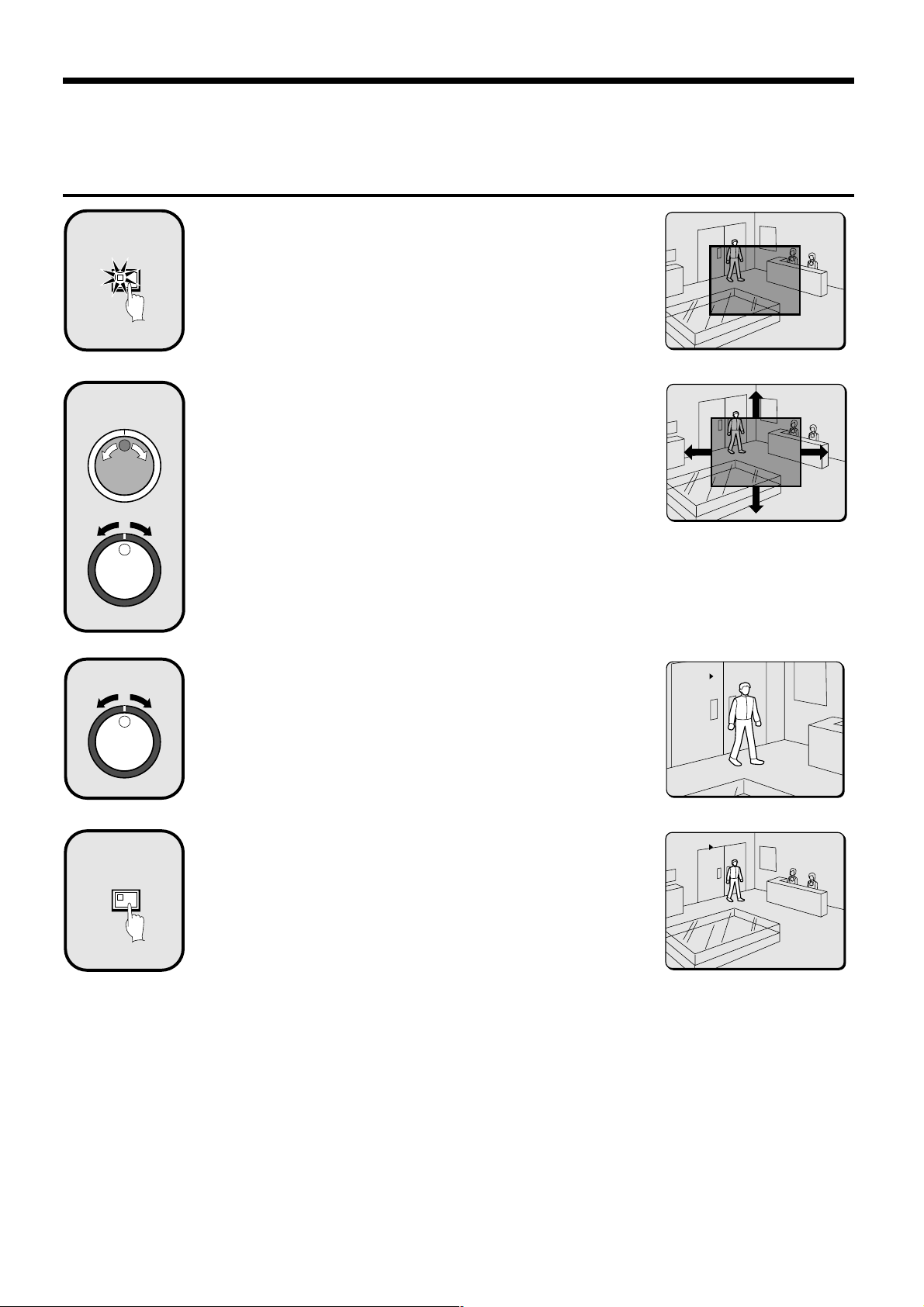
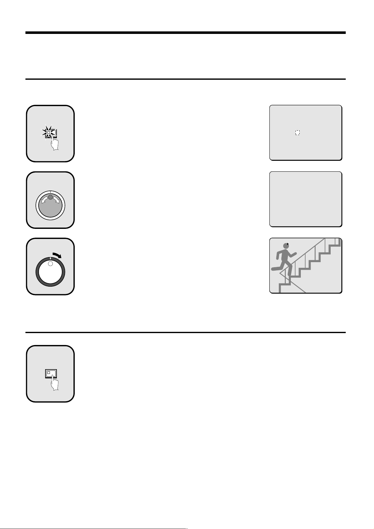
Zooming the image during playback
Press the ZOOM button during playback.
1
ZOOM
2
The zoom frame (blue) appears in the center of the screen.
Move the zoom frame to the position where the image is
to be enlarged.
Turn the jog dial clockwise to move the zoom frame to the right.
•
Turn it counterclockwise to move the zoom frame to the left.
Turn the shuttle dial clockwise to change to vertical movement. Then turn
•
the jog dial clockwise to move the zoom frame upward and turn it
counterclockwise to move the zoom frame downward.
Move the zoom frame to the position to be enlarged.
3
4
ZOOM
Turn the shuttle dial.
The area inside the zoom frame is enlarged (2x).
Press the ZOOM button (to cancel zooming).
The image zooming is canceled and normal playback continues.
Note:
The display cannot be enlarged even while monitoring a camera image.
•
The ZOOM button cannot be selected, when a multiplexer is used as a
•
video input.
The picture quality becomes coarser when the image is zoomed.
•
17-11-01
02:36:00 EN 0.12SEC
17-11-01
02:36:00 EN 0.12SEC
20
English
Page 22
PLAYING BACK IMAGES RECORDED IN THE NORMAL
RECORDING AREA
Viewing still images
Press the STILL button during playback.
1
2
h appears in the operating display and a still image is displayed.
STILL
Press the STILL button once more.
Still mode is canceled.
STILL
17-11-01
02:38:00 EN 0.12SEC
17-11-01
02:38:20 EN 0.12SEC
Frame advance (forward/reverse)
Turn the jog dial clockwise (or counterclockwise) in still
1
mode.
Turn the jog dial clockwise to advance the still image by one frame (one field).
Turn it counterclockwise to rewind the still image by one frame (one field).
Note: If the jog dial is turned quickly, the frame feed speed also increases.
During the following operations the picture may appear
distorted or momentarily frozen. This is normal and not a
malfunction.
During the continuous playback from the normal and
•
the alarm recording area, the picture may be distorted
when the recording area is switched.
When playing back during an alarm recording, during
•
continuous playback from the normal and alarm
recording area, during normal playback or when using
the fast forward/rewind playback the picture may
appear momentarily frozen.
17-11-01
02:50:08 EN 0.12SEC
English
21
Page 23
PLAYING BACK IMAGES RECORDED IN THE NORMAL
RECORDING AREA
Selecting a camera image channel for playback
When the digital video recorder has been connected to a multiplexer (sold separately) and camera images have been recorded, you can specify
the channel (camera number) for the images recorded and play them back.
Press the CHANNEL button while playback is paused.
1
CHANNEL
2
The screen for selecting the camera number for cameras connected to the
multiplexer appears.
Use the jog dial to specify the channel (example: camera
4).
PLEASE SELECT CHANNEL
-- CHANNEL
CHANGE WITH JOG. SET WITH SHUTTLE
PLEASE SELECT CHANNEL
4 CHANNEL
CHANGE WITH JOG. SET WITH SHUTTLE
Turn the shuttle dial clockwise.
3
“c” appears in the operating display, and playback of images from the
specified channel starts.
Note:
If the digital video recorder is not connected to a multiplexer that allows
•
decoding of channel information (camera numbers), channels can not be
specified for playback.
When this operation is carried out, only the specified channel is played
•
back, and so other channels are not displayed.
When a channel is selected, the multiplexer title information and date
•
information may not be fully displayed in some cases.
Switching between frame and field playback
Press the SEARCH FRAME/FIELD button while frame
1
FRAME/FIELD
SEARCH
recording images are being played back.
The screen changes between frame and field playback each time the button
is pressed.
Note:
Switching between frame and field playback is only possible when images
•
that have been recorded in frame mode are being played back.
When playing back of frame recording images that contain rapid
•
movement, instability may occur in the images.
CH4
27-10-01
13:38:33 SF 0.03SEC
22
English
Page 24

SEARCHING FOR RECORDED IMAGES
Images that have been recorded in the alarm recording area and in the archive area can be played back. Furthermore, images can also be
searched for by recording date and time, and you can also search for moving objects that have been detected by a motion sensor during image
playback.
a Alarm search (See page 24.)
Archive area
Alarm image search and playback
<ALARM SEARCH>
NO DATE TIME TOTAL ALARM
0108 13-12 11:13 0234
0107 13-12 11:15
0106 13-12 15:19
0105 15-12 10:13
0104 16-12 16:13
0103 16-12 11:13
0102 19-12 14:23
0101 20-12 05:37
MOVE:JOG SELECT:SHUTTLE
Preview display Single-screen display
Alarm recording area
SEARCH
FRAME/FIELD
<SEARCH>
ALARM SEARCH ->
ALARM THUMBNAIL SEARCH ->
TIME/DATE SEARCH ->
ARCHIVE AREA SEARCH ->
MOTION DETECTION SEARCH ->
MOVE:JOG SELECT:SHUTTLE
Alarm image thumbnail search and
playback
Searching and playing back recorded
images by date/time
Playing back images saved (copied) in
the archive area
a Alarm image thumbnail search (See page 25.)
0109 0108 0107
0106 0105 0104
0103 0102 0101
Thumbnail display
Single-screen display
a Time/date search (See page 26.)
<TIME DATE SEARCH>
RECORDING TOP : 15-12-00 08:00
RECORDING END : 22-12-00 17:00
SEARCH :
DATE TIME
20-12-00 05:37
PREVIEW ->
VIEW ->
CHANGE:JOG SET:SHUTTLE
Preview display
Single-screen display
a Archive area search (See page 28.)
<ARCHIVE AREA SEARCH>
NO DATE START CAPACITY
0108 13-12 11:13 TOTAL - 1024MB
0107 13-12 11:15 USED - 400MB
0106 13-12 15:19
0105 15-12 10:13
0104 16-12 16:13
0103 16-12 11:13
0102 19-12 14:23
0101 20-12 05:37
MOVE:JOG SELECT:SHUTTLE
Preview display
Single-screen display
English
Searching for and playing back moving
objects detected by a motion sensor
a Motion detection search (See page 29.)
<MOTION DETECTION SEARCH>
SEARCH FROM : NORMAL / CHANNEL : 4
START :
28-10-01 08:00
END :
28-10-01 20:00
MOTION SENSOR ->
PREVIEW ->
VIEW ->
MOVE:JOG SELECT:SHUTTLE
Date/time search of an image
----------
----------
---úúú----
---úúú----
---úúú----
----------
----------
----------
LEVEL : 6 EXIT
Motion sensor setting Single-screen display
for motion detection
23
<MOTION DETECTION SEARCH>
SEARCH FROM : NORMAL / CHANNEL : 4
START :
28-10-01 10:00
END :
28-10-01 20:00
MOTION SENSOR ->
PREVIEW ->
VIEW ->
MOVE:JOG SELECT:SHUTTLE
Preview display
Page 25

SEARCHING FOR RECORDED IMAGES
Alarm search
All alarm recording images in the alarm recording area can be searched for and played back. If pre-alarm images have is recorded, the images
immediately before the alarms can also be played back.
1
2
3
SEARCH
FRAME/FIELD
Press the SEARCH FRAME/FIELD button during
recording or when the digital video recorder is stopped.
The SEARCH screen appears.
Use the jog dial to select ALARM SEARCH and then turn
the shuttle dial clockwise.
The ALARM SEARCH screen appears.
NO: Alarm number appears.
1
DATE/TIME: The date and time that the alarm was received and the
2
images were recorded appears.
TOTAL ALARM: The total number of alarm images recorded appears.
3
Use the jog dial to move the cursor in order to select the
images to be played back.
The selected alarm image appears in the preview screen.
Note:
Up to eight items of alarm information can be displayed on the ALARM
•
SEARCH screen. When the jog dial is turned, the previous or next alarm
information screen appears.
To end this search mode, press the SEARCH FRAME/FIELD button.
•
<SEARCH>
ALARM SEARCH ->
ALARM THUMBNAIL SEARCH ->
TIME/DATE SEARCH ->
ARCHIVE AREA SEARCH ->
MOTION DETECTION SEARCH ->
MOVE:JOG SELECT:SHUTTLE
12 3
<ALARM SEARCH>
NO DATE TIME TOTAL ALARMS
008 13-12 11:13 0010
007 13-12 11:15
006 13-12 15:19
005 15-12 10:13
004 16-12 16:13
003 16-12 11:13
002 19-12 14:23
001 20-12 05:37
MOVE:JOG SELECT:SHUTTLE
<ALARM SEARCH>
NO DATE TIME TOTAL ALARM
008 13-12 11:13 0234
007 13-12 11:15
006 13-12 15:19
005 15-12 10:13
004 16-12 16:13
003 16-12 11:13
002 19-12 14:23
001 20-12 05:37
MOVE:JOG SELECT:SHUTTLE
4
Alarm search 2
1
ALARM
Turn the shuttle dial clockwise.
The preview image appears in a single-screen display and playback starts.
Note:
You can also use the shuttle dial or jog dial to carry out operations such
•
as pausing and fast-forward playback.
Alarm search starts playback from the image that was recorded at the
•
instant the alarm occurred, so if you are viewing pre-alarm images, use
the shuttle operations to carry out rewind playback.
Press an ALARM skip button during playback.
If you press the û button, playback skips to the previous alarm image.
•
If you press the ù button, playback skips to the next alarm image.
•
Note: When playing back using alarm search, the playback will pause at the
start and at the end of each alarm recording. Use the ALARM skip
buttons to play back previous and subsequent alarm recordings.
18-11-01 ALARM 0004
25:03:12 EN 0.12SEC
18-11-01 ALARM 0004
25:03:12 EN 0.12SEC
24
English
Page 26

SEARCHING FOR RECORDED IMAGES
Alarm thumbnail search
Alarm images can be searched for and played back from thumbnails.
All alarm images recorded in the alarm recording area are displayed as thumbnails.
1
2
3
SEARCH
FRAME/FIELD
Press the SEARCH FRAME/FIELD button during
recording or when the digital video recorder is stopped.
The SEARCH screen appears.
Use the jog dial to select ALARM THUMBNAIL SEARCH
and then turn the shuttle dial clockwise.
The last nine alarm recording images recorded appear.
The alarm number appears with each alarm recording image, and the alarm
number of the currently-selected alarm image flashes.
Use the jog dial to move the cursor in order to select the
images to be played back.
The alarm number of the currently-selected alarm image flashes.
Note:
Up to nine items of alarm information including thumbnails can be
•
displayed. When the jog dial is turned, the previous or next alarm
information screen appears.
To end this search mode, press the SEARCH FRAME/FIELD button.
•
<SEARCH>
ALARM SEARCH ->
ALARM THUMBNAIL SEARCH ->
TIME/DATE SEARCH ->
ARCHIVE AREA SEARCH ->
MOTION DETECTION SEARCH ->
MOVE:JOG SELECT:SHUTTLE
<SEARCH>
ALARM SEARCH ->
ALARM THUMBNAIL SEARCH ->
TIME/DATE SEARCH ->
ARCHIVE AREA SEARCH ->
MOTION DETECTION SEARCH ->
MOVE:JOG SELECT:SHUTTLE SEARCH:EXIT
0109 0108 0107
0106 0105 0104
0103 0102 0101
0109 0108 0107
0106 0105 0104
0103 0102 0101
4
English
Turn the shuttle dial clockwise.
The selected image appears in a single-screen display and playback starts.
Note:
You can also use the shuttle dial or jog dial to carry out operations such
•
as pausing and fast-forward playback.
Only the contents of each alarm can be played back, in the same way as
•
for alarm searching. Use the ALARM skip buttons to play back previous
and subsequent alarm recordings.
25
18-11-01 ALARM 0003
25:02:00 EN 0.12SEC
Page 27

SEARCHING FOR RECORDED IMAGES
Time/date search
The recording date and time for images in the normal recording area (normal recording and timer recording images) and in the alarm recording
area of the hard disk can be specified and the images can be played back.
1
FRAME/FIELD
2
SEARCH
Press the SEARCH FRAME/FIELD button during
recording or when the digital video recorder is stopped.
The SEARCH screen appears.
Use the jog dial to select TIME/DATE SEARCH and then
turn the shuttle dial clockwise.
The TIME/DATE SEARCH screen appears.
RECORDING TOP: The date and time of the first recorded image is
1
RECORDING END: The date and time of the latest (most recently)
2
SEARCH: Enter the date and time to be displayed in this area.
3
PREVIEW: A preview image appears.
4
VIEW: The selected image appears on the monitor as a single-screen
5
image.
displayed.
recorded image is displayed.
<SEARCH>
ALARM SEARCH ->
ALARM THUMBNAIL SEARCH ->
TIME/DATE SEARCH ->
ARCHIVE AREA SEARCH ->
MOTION DETECTION SEARCH ->
MOVE:JOG SELECT:SHUTTLE
<SEARCH>
ALARM SEARCH ->
ALARM THUMBNAIL SEARCH ->
TIME/DATE SEARCH ->
ARCHIVE AREA SEARCH ->
MOTION DETECTION SEARCH ->
MOVE:JOG SELECT:SHUTTLE
<TIME/DATE SEARCH>
RECORDING TOP : 25-10-01 08:00
1
RECORDING END : 28-10-01 17:00
2
SEARCH :
3
DATE TIME
25-10-01 08:00
PREVIEW ->
4
VIEW ->
5
CHANGE:JOG SET:SHUTTLE
3
Example: To search for 8 pm on 26 October 2001
Turn the jog dial clockwise, and then use the jog dial to change “25” to
1
“26”.
2 Turn the shuttle dial clockwise and select “10”.
3 Turn the shuttle dial clockwise and select “01”.
4 Turn the shuttle dial clockwise, and then use the jog dial to change “08” to
“20”.
5 Turn the shuttle dial clockwise and select “00”. Then turn the shuttle dial.
The cursor moves to PREVIEW.
<TIME/DATE SEARCH>
RECORDING TOP : 25-10-01 08:00
RECORDING END : 28-10-01 17:00
SEARCH :
DATE TIME
26-10-01 20:00
PREVIEW ->
VIEW ->
CHANGE:JOG SET:SHUTTLE
26
English
Page 28

SEARCHING FOR RECORDED IMAGES
4
Turn the shuttle dial clockwise.
A search display appears while searching is in progress, and then a preview
screen showing the date and time entered appears.
Note: If there are no images that match the time exactly, the image closest to
the selected time range is displayed.
Use the jog dial to select VIEW, and then turn the shuttle
5
dial clockwise.
The preview image is displayed and played back in a single-screen.
Note:
A single-screen image can be displayed when date and time are entered
•
and VIEW is selected, even without displaying a preview.
You can also use the shuttle dial or jog dial to carry out operations such
•
as pausing and fast-forward playback.
<TIME/DATE SEARCH>
RECORDING TOP : 15-12-00 08:00
RECORDING END : 22-12-00 17:00
SEARCH :
DATE TIME
17-11-01 02:36:10
PREVIEW ->
VIEW ->
CHANGE:JOG SET:SHUTTLE
17-11-01
02:36:10 EN 0.12SEC
English
27
Page 29

SEARCHING FOR RECORDED IMAGES
Archive area search
You can play back images that have been saved (copied) in the archive area.
1
FRAME/FIELD
2
SEARCH
Press the SEARCH FRAME/FIELD button during
recording or when the digital video recorder is stopped.
The SEARCH screen appears.
Use the jog dial to select ARCHIVE AREA SEARCH and
then turn the shuttle dial clockwise.
The ARCHIVE AREA SEARCH screen appears.
NO: The archive number is displayed.
1
DATE: The date of the recorded image is displayed.
2
TIME: The start time of the recorded image is displayed.
3
TOTAL: The total capacity of the archive area is displayed.
4
USED: The recorded part of the archive area is displayed.
5
<SEARCH>
ALARM SEARCH ->
ALARM THUMBNAIL SEARCH ->
TIME/DATE SEARCH ->
ARCHIVE AREA SEARCH ->
MOTION DETECTION SEARCH ->
MOVE:JOG SELECT:SHUTTLE
<SEARCH>
ALARM SEARCH ->
ALARM THUMBNAIL SEARCH ->
TIME/DATE SEARCH ->
ARCHIVE AREA SEARCH ->
MOTION DETECTION SEARCH ->
12 3 45
MOVE:JOG SELECT:SHUTTLE SEARCH:EXIT
<ARCHIVE AREA SEARCH>
NO DATE TIME CAPACITY
0108 13-12 11:13 TOTAL - 1024MB
0107 13-12 11:15 USED - 400MB
0106 13-12 15:19
0105 15-12 10:13
0104 16-12 16:13
0103 16-12 11:13
0102 19-12 14:23
0101 20-12 05:37
MOVE:JOG SELECT:SHUTTLE
3
4
Use the jog dial to move the cursor in order to select the
images to be played back.
The selected alarm image appears in the preview screen.
Note:
Up to eight items of information can be displayed in the ARCHIVE AREA
•
SEARCH screen.
When the jog dial is turned, the previous or next archive screen appears.
To end this search mode, press the SEARCH FRAME/FIELD button.
•
Turn the shuttle dial clockwise.
The selected image appears in a single-screen display and playback starts.
Note:
A single-screen image can be displayed when the cursor is moved to the
•
image to be played back and the shuttle dial is turned clockwise, even
without displaying a preview.
You can also use the shuttle dial or jog dial to carry out operations such
•
as pausing and fast-forward playback.
<ARCHIVE AREA SEARCH>
NO DATE TIME CAPACITY
0108 13-12 11:13 TOTAL - 1024MB
0107 13-12 11:15 USED - 400MB
0106 13-12 15:19
0105 15-12 10:13
0104 16-12 16:13
0103 16-12 11:13
0102 19-12 14:23
0101 20-12 05:37
MOVE:JOG SELECT:SHUTTLE
18-11-01 ALARM 0004
25:03:12 EN 0.12SEC
28
English
Page 30

SEARCHING FOR RECORDED IMAGES
Motion detection search
When a motion sensor is set for images recorded in the normal recording area (normal recording and timer recording images) or for images
recorded in the alarm recording area of the hard disk, you can search for images that have changed because of the entry of a suspicious
person, for instance, and play back only those images.
Note:
If carrying out motion detection searches of multiplexer images, change the setting for MULTIPLEXER in the VIDEO INPUT SET menu to
•
something other than “NO USE”.
If the digital video recorder is connected to a Sanyo multiplexer that allows decoding of channel information (camera numbers), channels can
•
be specified so that only images from those channels are searched for. If any other type of multiplexer is connected, this setting is not
possible.
1
FRAME/FIELD
2
3
SEARCH
Press the SEARCH FRAME/FIELD button during
recording or when the digital video recorder is stopped.
The SEARCH screen appears.
Use the jog dial to select MOTION DETECTION SEARCH
and then turn the shuttle dial clockwise.
The MOTION DETECTION SEARCH screen appears.
Use the jog dial to select SEARCH FROM and then turn
the shuttle dial clockwise.
The ALARM display flashes.
<SEARCH>
ALARM SEARCH ->
ALARM THUMBNAIL SEARCH ->
TIME/DATE SEARCH ->
ARCHIVE AREA SEARCH ->
MOTION DETECTION SEARCH ->
MOVE:JOG SELECT:SHUTTLE
<SEARCH>
ALARM SEARCH ->
ALARM THUMBNAIL SEARCH ->
TIME/DATE SEARCH ->
ARCHIVE AREA SEARCH ->
MOTION DETECTION SEARCH ->
<MOTION DETECTION SEARCH>
SEARCH FROM : ALARM
START : -------- --:- END : -------- --:--
CHANNEL : --
START PREVIEW ->
MOVE:JOG SELECT:SHUTTLE
4
5
English
Use the jog dial to select the recording area (example:
NORMAL), and then turn the shuttle dial clockwise.
The cursor moves to CHANNEL.
Note: If the setting for MULTIPLEXER in the VIDEO INPUT SET menu is set
to “NO USE”, the cursor will move to START PREVIEW.
Examples of recording area selection:
ALARM: Only images in the alarm recording area are searched.
•
NORMAL: Only images in the normal recording area are searched.
•
ALARM & NORMAL: Images in both the alarm recording area and the
•
normal recording area are searched.
Turn the shuttle dial clockwise, use the jog dial to select
the camera number (example: 4), and then turn the
shuttle dial clockwise.
The cursor moves to START PREVIEW.
29
<MOTION DETECTION SEARCH>
SEARCH FROM : NORMAL
START : 28-10-01 08:00
END : 28-10-01 20:00
CHANNEL : --
START PREVIEW ->
MOVE:JOG SELECT:SHUTTLE
<MOTION DETECTION SEARCH>
SEARCH FROM : NORMAL
START : 28-10-01 08:00
END : 28-10-01 20:00
CHANNEL : 4
START PREVIEW ->
MOVE:JOG SELECT:SHUTTLE
Page 31

SEARCHING FOR RECORDED IMAGES
6
7
Turn the shuttle dial clockwise.
The screen changes and the preview screen for camera number 4 appears.
START: The date and time for the first image in the selected recording
1
area appears.
You can also select the screen which has a motion sensor set.
END: The date and time for the last image in the selected recording area
2
appears.
One hour is added to the time that is displayed.
You can also select the screen which has a motion sensor set.
MOTION SENSOR: The motion sensor appears.
3
PREVIEW: The selected start point appears.
4
If you turn the shuttle dial clockwise, you can check the
images up until the end point.
VIEW: The selected image appears on the monitor as a single-screen
5
image in a normal screen.
Turn the shuttle dial clockwise.
Use the jog dial to set the START date and time (example: 10.00 am on the
current day) for the motion sensor setting, and then turn the shuttle dial
clockwise.
The image for the specified time appears in the preview screen, and the
cursor moves to the END date and time setting location.
<MOTION DETECTION SEARCH>
SEARCH FROM : NORMAL
START : 28-10-01 08:00
END : 28-10-01 20:00
CHANNEL : 4
START PREVIEW -> SEARCHING
MOVE:JOG SELECT:SHUTTLE
<MOTION DETECTION SEARCH>
SEARCH FROM : NORMAL / CHANNEL : 4
START :
28-10-01 08:00
1
END :
28-10-01 10:00
2
MOTION SENSOR ->
3
PREVIEW ->
4
VIEW ->
5
MOVE:JOG SELECT:SHUTTLE
<MOTION DETECTION SEARCH>
SEARCH FROM : NORMAL / CHANNEL : 4
START :
28-10-01 08:00
END :
28-10-01 20:00
MOTION SENSOR ->
PREVIEW ->
VIEW ->
MOVE:JOG SELECT:SHUTTLE
8
9
Turn the shuttle dial clockwise.
Use the jog dial to set the END date and time (example: 8.00 pm on the
current day) for the motion sensor setting, and then turn the shuttle dial
clockwise.
The cursor moves to MOTION SENSOR.
Turn the shuttle dial clockwise.
The motion sensor setting screen appears.
Set the motion sensor to cover the area where you would like movement to
be observed.
Move the cursor to EXIT and turn the shuttle dial clockwise. The display
returns to the MOTION DETECTION SEARCH screen. Refer to page 56 for
details on motion sensor settings.
<MOTION DETECTION SEARCH>
SEARCH FROM : NORMAL / CHANNEL : 4
START :
28-10-01 10:00
END :
28-10-01 20:00
MOTION SENSOR ->
PREVIEW ->
VIEW ->
MOVE:JOG SELECT:SHUTTLE
<MOTION DETECTION SEARCH>
SEARCH FROM : NORMAL / CHANNEL : 4
START :
28-10-01 10:00
END :
28-10-01 20:00
MOTION SENSOR ->
PREVIEW ->
VIEW ->
MOVE:JOG SELECT:SHUTTLE
----------
----------
---úúú----
---úúú----
---úúú----
----------
----------
----------
LEVEL : 6 EXIT
30
English
Page 32

SEARCHING FOR RECORDED IMAGES
10
11
1
1
2
2
Use the jog dial to move the cursor to PREVIEW, and then
turn the shuttle dial clockwise. The screen showing the
motion sensor settings appear in the preview screen
each time the shuttle dial is turned.
Note: If no motion sensor settings have been made, “NOT FOUND” appears,
so make sure that the motion sensor settings have been made
correctly.
To view a motion sensor setting in a single-screen
display, use the jog dial to move the cursor to VIEW and
then turn the shuttle dial clockwise.
The display changes from the specified image to normal playback.
Note: When using a multiplexer and the camera number has been specified
as a channel when carrying out motion detector searches, only images
for the specified camera number will be played back. For playback of
all cameras the playback has first to be switched off and then switched
on again. Furthermore, the multiplexer title information and date
information may not be fully displayed at this time in some cases.
<MOTION DETECTION SEARCH>
SEARCH FROM : NORMAL / CHANNEL : 4
START :
28-10-01 10:00
END :
28-10-01 20:00
MOTION SENSOR ->
PREVIEW ->
VIEW ->
MOVE:JOG SELECT:SHUTTLE
English
31
Page 33

SAVING (COPYING) RECORDED IMAGES
Important images that have been recorded onto the normal recording area or alarm recording area can be copied to a CompactFlash card or to
the archive area of the hard disk.
Images can be copied to the
archive area of the hard disk.
Hard disk
Important recorded images
can be selected for copying.
CF card or microdrive
Note:
Copied images are stored as a single picture.
•
If you are downloading images to a CompactFlash card, the images are automatically saved in the archive area, and they are then copied
•
from the archive area to the CompactFlash card.
If the archive area has become full, use the AREA FULL RESET setting for the archive area in the RECORDING AREA SET menu to delete
•
unneeded images.
Images can be copied to a
CompactFlash card or to a
microdrive.
Copying images to the hard disk archive area
Play back the images in the normal recording area or alarm recording area
1
PLAY/STOP
STILL
that is to be copied, and pause playback at the image that is to be copied.
(See page 21.)
Example: To copy 10 seconds of images starting from a selected image
While the image to be copied is displayed as a still image,
2
COPY
press the COPY button.
The copy screen appears.
Use the jog dial to select COPY TO and then turn the
3
shuttle dial clockwise.
The ARCHIVE AREA display flashes.
32
COPY TO : ARCHIVE AREA
HOW MANY : 1 PICTURES
START ->
CHANGE WITH JOG. SET WITH SHUTTLE
COPY TO : ARCHIVE AREA
HOW MANY : 1 PICTURES
START ->
CHANGE WITH JOG. SET WITH SHUTTLE
English
Page 34

SAVING (COPYING) RECORDED IMAGES
Use the jog dial to select ARCHIVE AREA and then turn
4
the shuttle dial clockwise.
The cursor moves to HOW MANY.
Turn the shuttle dial clockwise, use the jog dial to change
5
the setting to “10”, and then turn the shuttle dial
clockwise.
The cursor moves to PICTURES.
Use the jog dial to select the SECONDS setting, and then
6
turn the shuttle dial clockwise.
PICTURES: Specify the number of images to be copied.
•
SECONDES: Specify the number of seconds of images to be copied.
•
MINUTES: Specify the number of minutes of images to be copied (up to
•
The cursor moves to START.
Turn the shuttle dial clockwise.
7
Copying of images to the archive area starts. When copying is complete,
“COPY FINISHED” appears.
Note: If you press the COPY button while copying is in progress, copying is
canceled.
60 minutes).
COPY TO : ARCHIVE AREA
HOW MANY : 1 PICTURES
COPY TO : ARCHIVE AREA
HOW MANY : 10 PICTURES
COPY TO : ARCHIVE AREA
HOW MANY : 10 PICTURES
START ->
Copying images from archive area to a CompactFlash card
Insert a CompactFlash card into the CompactFlash slot
1
on the front panel.
When inserting the CompactFlash card, make sure that the direction of
insertion is correct.
A microdrive can also be used for copying images.
(Inserting) (Removing)
1
2
3
Display an image from the archive area as a still image,
2
COPY
and then press the COPY button.
The copying screen appears.
Refer to page 28 for details on playing back images from the archive area.
3
2
1
COPY TO : ARCHIVE AREA
HOW MANY : 1 PICTURES
START ->
3
English
Use the jog dial to select COPY TO and then turn the
shuttle dial clockwise.
The ARCHIVE AREA display flashes.
33
CHANGE WITH JOG. SET WITH SHUTTLE
COPY TO : ARCHIVE AREA
HOW MANY : 1 PICTURES
START ->
CHANGE WITH JOG. SET WITH SHUTTLE
Page 35

SAVING (COPYING) RECORDED IMAGES
Use the jog dial to select COMPACIT FLASH and then
4
turn the shuttle dial clockwise.
The cursor moves to HOW MANY.
Turn the shuttle dial clockwise, use the jog dial to change
5
the setting to “10”, and then turn the shuttle dial
clockwise.
The cursor moves to PICTURES.
Use the jog dial to select the SECONDS setting, and then
6
turn the shuttle dial clockwise.
PICTURES: Specify the number of images to be copied.
•
SECONDES: Specify the number of seconds of images to be copied.
•
MINUTES: Specify the number of minutes of images to be copied (up to
•
Note:
The limit to the number of images that can be copied to CompactFlash is
•
1000. Copying ends when 1000 images have been copied.
When copying alarm recordings, they can only be copied one at a time.
•
Turn the shuttle dial clockwise.
7
The COPY indicator illuminates, the COPY TO : COMPACT FLASH screen
appears and copying of images to the CompactFlash card starts.
When copying is complete, “COPYING COMPLETE” appears.
Note:
If copying images directly from the normal recording area or alarm
•
recording area to a CompactFlash card, the same images will also be
copied to the archive area.
If you press the COPY button while copying is in progress, copying is
•
canceled.
60 minutes).
COPY TO : COMPACT FLASH
HOW MANY : 1 PICTURES
COPY TO : COMPACT FLASH
HOW MANY : 10 PICTURES
COPY TO : COMPACT FLASH
HOW MANY : 10 SECONDES
COPY TO : COMPACT FLASH
HOW MANY : 10 SECONDES
START ->
CompactFlash recording area
A SANYO folder is created in the root directory.
1
Sub-folders for holding the copied images are created in
2
sequence in the SANYO folder.
The images are copied as JPEG files into the sub-folders,
3
with filenames starting from 00000001.JPG.
HTML files called INDEX.HTM containing the number of files
that have been copied to a folder are also copied to each
folder at this time.
To view the file listing using a computer, use a browser such
4
as Internet Explorer 5.0 or later to open the INDEX.HTM files.
The JPEG files can be played back as a slideshow.
Note:
When frame recording images are copied to a CompactFlash card, the images are copied separately as two field images, so that frame
•
playback is not possible when viewing these images using a computer.
Images that have been copied onto a CompactFlash card contain codes for detecting file tampering, and these codes can be recognized by
•
computer software applications that can detect file tampering. Contact the place of purchase for details.
JPG images are recorded as field images, so that when they are viewed using the normal image viewer, they are compressed by 1/2 in the
•
vertical direction. Make sure that you view them using the index.htm file.
COMPACT FLASH
SANYO 00000001 00000001.JPG
12
00000002
2
00000002.JPG
INDEX.HTM
00000001.JPG
00000002.JPG
00000003.JPG
00000004.JPG
INDEX.HTM
3
3
4
4
34
English
Page 36

SAVING (COPYING) RECORDED IMAGES
Copying to a DDS (DAT) drive
Insert an SCSI card (sold separately) for connecting the
1
DDS (DAT) drive into the PC card slot at the rear of the
digital video recorder.
Images from the archive area can be copied to the DDS (DAT) drive, and
images recorded on the DDS (DAT) drive can also be copied to the archive
area.
Backing up
(Installed)
1
You can slide the
knob to lock the
card.
• Recommended SCSI card
Manufacturer: ADAPTEC
Model No.: Slim SCSI 1460
• Recommended DDS-3 type DDS (DAT) drive
Manufacturer: Hewlett Packard
Model No.: Super Store dat 24e
Note:
Check that the direction of insertion is correct wehn inserting the SCSI card.
•
If an SCSI card or DDS (DAT) drive other than the ones recommended is
•
used, correct operation cannot be guaranteed.
DDS (Digital Data Strage)/DAT (Digital Audio Tape).
•
2
3
(Removed)
Return the knob
after unlocking.
Be sure to attach the accessory ferrite core
to the SCSI card connection cable.
1
3
2
All of the data in the archive area can be backed up on a DDS (DAT) drive.
Press the COPY button during recording or when the
2
COPY
digital video recorder is stopped.
The ARCHIVE SET screen appears.
Use the jog dial to select BACK UP and then turn the
3
shuttle dial clockwise.
“ARCHIVING TO DDS(DAT) !” appears, and copying then starts.
If you press the COPY button while copying is in progress, copying is
•
canceled.
When copying is completed, “ARCHIVE FINISHED!” appears. Press any
•
button to return to the normal screen.
Note:
When data is converted for storage on a DDS (DAT) drive, the conversion
•
process may result in an increase in the size of the data. If copying
images onto a 12 GB tape, it may only be possible to copy about 10 GB of
data.
It will take approximately 4 hours to copy 10 GB of data onto a DDS (DAT)
•
drive.
<ARCHIVE SET>
BACK UP ->
RESTORE ->
ERASE ->
01-01-01
00:00:00 EN 0.12SEC
ARCHIVING TO DDS(DAT) !
<PRESS COPY TO ABORT>
English
35
Page 37

SAVING (COPYING) RECORDED IMAGES
Reading data from a DDS (DAT) drive into the archive area
Note: All of the previously recorded images in the archive area are deleted when images are transferred in this way.
1
2
3
COPY
Press the COPY button during recording or when the
digital video recorder is stopped.
The ARCHIVE SET screen appears.
Use the jog dial to select RESTORE and then turn the
shuttle dial clockwise.
The message “LISTING DATA !” appears. When playback is complete, the
RESTORE FROM DDS (DAT) screen appears.
Use the jog dial to select the data to be read into the
archive area, and then turn the shuttle dial clockwise.
Reading of data starts. The RESTORE FROM DDS (DAT) screen appears.
The image data on the DDS (DAT) drive is then saved into the archive area.
When all data has been read into the archive area, “RESTORE FINISHED!”
appears.
When you play back the images in the archive area, the image data that has
been read can be played back.
<ARCHIVE SET>
BACK UP ->
RESTORE ->
ERASE ->
01-01-01
08:00:00 EN 0.12SEC
LISTING DATA !
<PRESS COPY TO ABORT>
<RESTORE FROM DDS(DAT)>
NO DATE TIME SIZE
0001 13-12-2001 11:13 3.0GB
0002 15-12-2001 10:15 2.0GB
0003 17-12-2001 10:15 2.0GB
STORED DATA ON HDD WILL BE ERASED !
01-01-01
08:00:00 EN 0.12SEC
RESTORING FROM DDS(DAT) !
<PRESS COPY TO ABORT>
36
English
Page 38

SAVING (COPYING) RECORDED IMAGES
Deleting DDS (DAT) drive image data
1
2
3
COPY
Press the COPY button during recording or when the
digital video recorder is stopped.
The ARCHIVE SET screen appears.
Use the jog dial to select ERASE and then turn the shuttle
dial clockwise.
The WARNING screen appears.
Use the jog dial to change “NO” to “YES”, and then turn
the shuttle dial clockwise.
“ERASING MEDIUM!” appears, and when erasing of data from the tape has
been completed, “ERASING FINISHED!” appears.
<ARCHIVE SET>
BACK UP ->
RESTORE ->
ERASE ->
<WARNING>
STORED DATA ON DDS(DAT) WILL BE ERASED !
ARE YOU SURE ?
NO
CHANGE WITH JOG, SET WITH SHUTTLE
01-01-01
08:00:00 EN 0.12SEC
ERASING MEDIUM !
English
37
Page 39

MENU FLOW CHART AND MENU
OPERATIONS
Menu flow
Settings for recording
Settings for operating environment
Main menu 1 contains settings that deal mainly with recording. Main menu 2 contains settings that deal mainly with the
operating environment.
Main menu 1
<MAIN MENU 1>
1.LANGUAGE/CLOCK SET ->
2.VIDEO INPUT SET ->
3.RECORDING AREA SET ->
4.RECORDING CONDITIONS SET ->
5.NORMAL REC MODE SET ->
6.TIMER SET ->
7.HOLIDAY SET ->
8.ALARM REC MODE SET ->
TO MAIN MENU 2 ->
MOVE LINES WITH JOG. SELECT WITH SHUTTLE
Main menu 2
<MAIN MENU 2>
1.DISPLAY SET/VIDEO LOSS SET ->
2.RS-232C/RS-485 SET ->
3.BUZZER SET ->
4.SECURITY LOCK SET ->
5.NETWORK SET ->
6.HDD SET ->
7.POWER FAILURE/USED TIME ->
TO MAIN MENU 1 ->
MOVE LINES WITH JOG. SELECT WITH SHUTTLE
Sub-menus
b
Language, clock and summer time
settings (See page 40, 41.)
<LANGUAGE/LANGUE/SPRACHE/IDIOMA>
ENGLISH
<CLOCK SET>
01-01-2001 MON 00:00:00
<SUMMER TIME SET>
MODE : USE
WEEK MONTH TIME
ON LST-SUN 03 02:00
OFF LST-SUN 10 02:00
<EXT.CLOCK SET>
ADJUST.TIME 01:00
b Normal recording area
settings (See page 47.)
<NORMAL REC MODE SET>
PICTURE QUALITY : ENHANCED
FRAME/FIELD RECORDING : FIELD
AUDIO RECORDING : OFF
REC CYCLE : 0.12 SEC ( 65H)
b Operating display settings
(See page 57.)
<DISPLAY SET>
DATE : ON
TIME : ON
QUALITY : ON
REC CYCLE : ON
ALARM COUNT : ON
ALARM TYPE : ON
<VIDEO LOSS SET>
VIDEO LOSS : ON
b Network settings
(See page 64.)
<NETWORK SET>
LAN CARD : LAN1
NETWORK CONTROL : OFF
IP ADDRESS : 192.168. 0. 1
SUBNET MASK : 255.255.255. 0
GATEWAY : 0. 0. 0. 0
PASSWORD SETTING
ID : PASSWORD (4-8)
ID1 : 1111--- ID2 : 2222--- ID3 : 3333----
b Multiplexer and video input
settings (See page 42.)
<VIDEO INPUT SET>
MULTIPLEXER : NO USE
VIDEO INPUT : ANALOG
b Recording area settings
(See page 43.)
<RECORDING AREA SET>
TOTAL CAPACITY : 80GB
NORMAL RECORDING AREA : 80 %
AREA FULL RESET ->
ALARM RECORDING AREA : 19 %
AREA FULL RESET ->
ARCHIVE AREA : 1 %
AREA FULL RESET ->
CAUTION : WHEN THE AREA SETTING IS CHANGED.
THE WHOLE AREA WILL BE INITIALIZED !
b Recording settings
(See page 45.)
<RECORDING CONDITIONS SET>
DIGITAL SERIES RECORDING : OFF
TOTAL NUMBER : ¤¤
RECORDING NUMBER : ¤¤
NORMAL RECORDING AREA
OVERWRITE : ON
ALARM RECORDING AREA
OVERWRITE : ON
REMAINING DISK WARNING : ¤¤
b Timer settings
(See page 48.)
<TIMER SET>
WEEK START STOP REC CYCLE SET
SUN --:-- --:-- 0.12SEC ( 65H) OFF
MON --:-- --:-- 0.12SEC ( 65H) OFF
TUE --:-- --:-- 0.12SEC ( 65H) OFF
WED --:-- --:-- 0.12SEC ( 65H) OFF
THU --:-- --:-- 0.12SEC ( 65H) OFF
FRI --:-- --:-- 0.12SEC ( 65H) OFF
SAT --:-- --:-- 0.12SEC ( 65H) OFF
DLY --:-- --:-- 0.12SEC ( 65H) OFF
b Holiday settings
(See page 51.)
<HOLIDAY SET>
1. ----- 11. -----
2. ----- 12. -----
3. ----- 13. -----
4. ----- 14. -----
5. ----- 15. -----
6. ----- 16. -----
7. ----- 17. -----
8. ----- 18. -----
9. ----- 19. -----
10. ----- 20. -----
b Alarm recording settings
(See page 52.)
<ALARM REC MODE SET>
PICTURE QUALITY :
FRAME/FIELD RECORDING : FIELD
AUDIO RECORDING : OFF
ALARM RECORDING : OFF
REC CYCLE : 0.12SEC. DURATION: 1SEC
PRE-ALARM RECORDING : ¤¤¤
REC CYCLE : ¤¤¤ SEC. DURATION: ¤¤¤
=> (55682 ALARMS CAN BE RECORDED)
ALARM TRIGGER : ALARM
MOTION SENSOR ->
ENHANCED
RS-232C/RS-485 communication
b
settings (See page 58.)
<RS-232C/RS-485 SET>
CONTROL : RS-232C
DATA SPEED : 19200
STATUS INFO : ¤¤¤
ALARM INFO : ¤¤¤
ADDRESS : ¤¤¤
b Buzzer settings
(See page 60.)
<BUZZER SET>
ALARM : OFF
DISK FULL : ON
DISK ERROR : ON
LOCK WARNING : ON
KEY IN : OFF
NON REC : OFF
b Security lock settings
(See page 61.)
<SECURITY LOCK>
LEVEL PASSWORD(4-8) USE
ADMIN -------- OFF
USER -------- OFF
REC CONTROL : ADMIN
b Hard disk settings
(See page 67.)
<HDD SET>
DISK1 : 80GB
DISK2 : ---GB
DISK INITIALIZE ->
CAUTION : ALL RECORDING WILL BE ERASED!
MIRRORING : OFF
PLAYBACK DRIVE : ¤¤¤
CAUTION : RECORDING SPEED WILL BE
LIMITED BY MIRRORING!
b Power failure/used time
settings (See page 68.)
<POWER FAILURE/USED TIME>
POWER FAILURE
FAILURE ----- --:- RECOVER ----- --:--
USED TIME
DISK1 USE : 00000H
DISK2 USE : -----H
POWER : 00000H
38
English
Page 40

MENU FLOW CHART AND MENU OPERATIONS
Basic menu screen operations
Press the MENU button.
1
The MAIN MENU 1 screen appears. If you press the MENU
button once more, the MAIN MENU 2 screen appears.
MENU
Note: If you repeatedly press the MENU button, the screen toggles
between MAIN MENU 1 and MAIN MENU 2. Furthermore,
you can also select “TO MAIN MENU 2” or “TO MAIN MENU
1” in the respective menu screens to display the other menu
screen.
Turn the jog dial to the left or right to move the cursor to
2
the menu items.
The selected item is highlighted.
<MAIN MENU 1>
1.LANGUAGE/CLOCK SET ->
2.VIDEO INPUT SET ->
3.RECORDING AREA SET ->
4.RECORDING CONDITIONS SET ->
5.NORMAL REC MODE SET ->
6.TIMER SET ->
7.HOLIDAY SET ->
8.ALARM REC MODE SET ->
TO MAIN MENU 2 ->
MOVE LINES WITH JOG. SELECT WITH SHUTTLE
MENU
<MAIN MENU 2>
1.DISPLAY SET/VIDEO LOSS SET ->
2.RS-232C/RS-485 SET ->
3.BUZZER SET ->
4.SECURITY LOCK SET ->
5.NETWORK SET ->
6.HDD SET ->
7.POWER FAILURE/USED TIME ->
TO MAIN MENU 1 ->
MOVE LINES WITH JOG. SELECT WITH SHUTTLE
Press the EXIT/OSD button.
4
The display returns to the normal screen.
EXIT/OSD
Operations while a sub-menu screen is
displayed
If you press the MENU button while a sub-menu screen is
displayed, you can check the settings in the sub-menu screens.
<VIDEO INPUT SET>
MULTIPLEXER : NO USE
VIDEO INPUT : ANALOG
MENU
<RECORDING AREA SET>
TOTAL CAPACITY : 80GB
NORMAL RECORDING AREA : 80 %
AREA FULL RESET ->
ALARM RECORDING AREA : 19 %
AREA FULL RESET ->
ARCHIVE AREA : 1 %
AREA FULL RESET ->
CAUTION : WHEN THE AREA SETTING IS CHANGED.
THE WHOLE AREA WILL BE INITIALIZED !
MENU
Turn the shuttle dial clockwise.
3
The sub-menu appears.
<MAIN MENU 1>
1.LANGUAGE/CLOCK SET ->
2.VIDEO INPUT SET ->
3.RECORDING AREA SET ->
4.RECORDING CONDITIONS SET ->
5.NORMAL REC MODE SET ->
6.TIMER SET ->
7.HOLIDAY SET ->
8.ALARM REC MODE SET ->
TO MAIN MENU 2 ->
MOVE LINES WITH JOG. SELECT WITH SHUTTLE
<VIDEO INPUT SET>
MULTIPLEXER : NO USE
VIDEO INPUT : ANALOG
Note: You can display menus even while images are being
<RECORDING CONDITIONS SET>
DIGITAL SERIES RECORDING : OFF
TOTAL NUMBER : ¤¤
RECORDING NUMBER : ¤¤
NORMAL RECORDING AREA
OVERWRITE : ON
ALARM RECORDING AREA
OVERWRITE : ON
REMAINING DISK WARNING : ¤¤
recorded in one of the recording areas. In such cases, the
recording symbol <a> appears on the screen. The menus
can only be displayed at this time; the settings cannot be
changed.
English
39
Page 41

LANGUAGE/CLOCK SET SETTINGS
This sub-menu lets you set the language for menu screens, the date and time that appear on the screen at all times, and summer time. It also
includes a function that lets you synchronize the time settings when more than one device is connected.
Main menu 1 Sub-menus
<MAIN MENU 1>
1.LANGUAGE/CLOCK SET ->
2.VIDEO INPUT SET ->
3.RECORDING AREA SET ->
4.RECORDING CONDITIONS SET ->
5.NORMAL REC MODE SET ->
6.TIMER SET ->
7.HOLIDAY SET ->
8.ALARM REC MODE SET ->
TO MAIN MENU 2 ->
MOVE LINES WITH JOG. SELECT WITH SHUTTLE
<LANGUAGE/LANGUE/SPRACHE/IDIOMA>
ENGLISH
<CLOCK SET>
01-01-2001 MON 00:00:00
<SUMMER TIME SET>
MODE : USE
WEEK MONTH TIME
ON LST-SUN 03 02:00
OFF LST-SUN 10 02:00
<EXT.CLOCK SET>
ADJUST.TIME 01:00
Setting the language
The menus can be displayed in one of several languages (English,
French, German and Spanish). The default language setting is
English.
Press the MENU button to select LANGUAGE/CLOCK
1
SET, and then turn the shuttle dial clockwise.
The LANGUAGE/LANGUE/SPRACHE/IDIOMA sub-menu
appears, and the cursor is moves to “ENGLISH”.
MENU
<LANGUAGE/LANGUE/SPRACHE/IDIOMA>
ENGLISH
<CLOCK SET>
01-01-2001 MON 00:00:00
<SUMMER TIME SET>
MODE : USE
WEEK MONTH TIME
ON LST-SUN 03 02:00
OFF LST-SUN 10 02:00
<EXT.CLOCK SET>
ADJUST.TIME 01:00
Sets the language.
Sets the date and time.
Set summer time.
Synchronizes the time for multiple devices.
CLOCK SET settings
(default setting: 01-01-2001 MON 00:00:00)
You should always set the date and time correctly. This digital
video recorder includes the recording time with recorded images,
and uses this time for playback and searching.
Example: To set the date and time to 8.30 a.m. on 22 May 2002
When the cursor is at the date and time setting, turn the
1
shuttle dial clockwise.
“01” flashes.
<LANGUAGE/LANGUE/SPRACHE/IDIOMA>
ENGLISH
<CLOCK SET>
01-01-2001 MON 00:00:00
<SUMMER TIME SET>
MODE : USE
WEEK MONTH TIME
ON LST-SUN 03 02:00
OFF LST-SUN 10 02:00
<EXT.CLOCK SET>
ADJUST.TIME 01:00
Turn the shuttle dial clockwise.
2
“ENGLISH” flashes.
<LANGUAGE/LANGUE/SPRACHE/IDIOMA>
ENGLISH
<CLOCK SET>
01-01-2001 MON 00:00:00
Turn the jog dial to select the language (example:
3
“FRANCAIS”), and then turn the shuttle dial clockwise.
The language is switched to French and the cursor moves to
the date and time.
2
1
<REGL.LANGUE>
FRANCAIS
<REGL.HORLOGE>
01-01-2001 LUN 00:00:00
<HEURE D’ETE>
MODE : ARRET
SEMAIN MOIS HEURE
ON DER-DIM 03 02:00
OFF DER-DIM 10 02:00
<REGL.HORLOGE EXTERNE>
REGL.DE L’HEURE 01:00
Turn the jog dial to select “22: day”, and then turn the
2
shuttle dial clockwise.
The cursor moves to the “01” month setting and flashes.
2
22-01-2001 MON 00:00:00
1
Use the same procedure to set the month (5), year (2002),
3
hour (08), minutes (30) and seconds.
After the seconds have been set, the cursor moves to the
ADJUST TIME setting for “EXT. CLOCK SET”, and counting
starts from zero seconds.
Note: Time stops during clock setting.
40
English
Page 42

LANGUAGE/CLOCK SET SETTINGS
SUMMER TIME SET setting
(default setting: USE)
This can be used to set the starting time and ending time for
summer time. When summer time is set, the time is automatically
advanced by one hour.
Example: To start summer time at 2.00 a.m. on the first
1
2
Sunday in April, and end it at 2.00 a.m. on the 4th
Sunday in October
When the cursor is at the MODE setting, turn the shuttle
dial clockwise.
“USE” flashes.
<SUMMER TIME SET>
MODE : USE
WEEK MONTH TIME
ON LST-SUN 03 02:00
OFF LST-SUN 10 02:00
<EXT.CLOCK SET>
ADJUST.TIME 01:00
Turn the shuttle dial clockwise.
The cursor moves to the starting time (ON) entry line.
ON LST-SUN 03 02:00
Turn the shuttle dial clockwise.
3
“LST” (WEEK) setting flashes.
ON LST-SUN 03 02:00
Turn the jog dial clockwise to select “1ST”, and then turn
4
the shuttle dial.
“SUN” (WEEK) flashes.
EXT. CLOCK SET setting
(default setting: 01:00)
If more than two devices are connected at the same time, the time
settings (ADJUST TIME) for the digital video recorder are also
applied to these devices.
Connect the other devices to the input terminal (CLOCK
1
ADJUST IN) and output terminal (CLOCK ADJUST OUT) at
the rear of the digital video recorder.
ALARM
RESET
ALARM
ALARM
OUT
IN
Turn the jog dial to move the cursor to the ADJUST TIME
2
setting, and then turn the shuttle dial.
“01” flashes.
Turn the jog dial to set the hours (example: “05”), and
3
then turn the shuttle dial.
ADJUST
NON REC
OUT
CC
CLOCK
OUT
WARNING
FULLOUTIN
ALARM
FULL
2
1
ALARM
RESET
ALARM
ALARM
IN
<LANGUAGE/LANGUE/SPRACHE/IDIOMA>
ENGLISH
<CLOCK SET>
01-01-2001 MON 00:00:00
<SUMMER TIME SET>
MODE : USE
WEEK MONTH TIME
ON LST-SUN 03 02:00
OFF LST-SUN 10 02:00
<EXT.CLOCK SET>
ADJUST.TIME 01:00
OUT
NON REC
OUT
CC
CLOCK
ADJUST
OUT
WARNING
FULLOUTIN
ALARM
FULL
ON 1ST-SUN 03 02:00
Turn the jog dial clockwise to select “SUN”, and then turn
5
the shuttle dial clockwise.
“03” (MONTH) flashes.
Turn the jog dial clockwise to select “04”, and then turn
6
the shuttle dial clockwise.
“02” (TIME) flashes.
<SUMMER TIME SET>
2
1
Use the same procedure to set the end of summer time.
7
The cursor moves to ADJUST TIME.
MODE : USE
WEEK MONTH TIME
ON 1ST-SUN 04 02:00
OFF LST-SUN 10 02:00
<EXT.CLOCK SET>
ADJUST.TIME 01:00
<EXT.CLOCK SET>
ADJUST.TIME 05:00
Press the EXIT/OSD button.
4
The display returns to the normal screen.
EXIT/OSD
Use the same procedure to set ADJUST TIME for the
5
second device.
When the settings are complete, the display returns to the
normal screen.
English
41
Page 43

VIDEO INPUT SET SETTING
If you select a multiplexer (sold separately) that is connected to the digital video recorder, you can set the type of image input (digital or analog).
Main menu 1 Sub-menus
<MAIN MENU 1>
1.LANGUAGE/CLOCK SET ->
2.VIDEO INPUT SET ->
3.RECORDING AREA SET ->
4.RECORDING CONDITIONS SET ->
5.NORMAL REC MODE SET ->
6.TIMER SET ->
7.HOLIDAY SET ->
8.ALARM REC MODE SET ->
TO MAIN MENU 2 ->
MOVE LINES WITH JOG. SELECT WITH SHUTTLE
<VIDEO INPUT SET>
MULTIPLEXER : NO USE
VIDEO INPUT : ANALOG
MULTIPLEXER setting
(default setting: NO USE)
Press the MENU button to select VIDEO INPUT SET, and
1
then turn the shuttle dial clockwise.
The VIDEO INPUT SET sub-menu appears, and the cursor
moves to MULTIPLEXER.
MENU
Turn the shuttle dial clockwise.
2
“NO USE” flashes.
Turn the jog dial to select the MULTIPLEXER setting
3
(example: “SANYO”), and then turn the shuttle dial
clockwise.
Display examples:
NO USE: When not using a multiplexer
•
SANYO: When using a Sanyo multiplexer
•
OTHERS1: When using a Sony multiplexer
•
OTHERS2: When using a Robot or DM multiplexer
•
The cursor moves to VIDEO INPUT.
2
1
<VIDEO INPUT SET>
MULTIPLEXER : NO USE
VIDEO INPUT : ANALOG
<VIDEO INPUT SET>
MULTIPLEXER : NO USE
VIDEO INPUT : ANALOG
<VIDEO INPUT SET>
MULTIPLEXER : SANYO
VIDEO INPUT : ANALOG
Sets the manufacturer of the connected
multiplexer.
Sets the video input.
VIDEO INPUT setting
(default setting: ANALOG)
This sets whether the image signals that are being input to the
video input terminals of this digital video recorder are digital or
analog.
When the cursor is at the VIDEO INPUT setting, turn the
1
shuttle dial clockwise.
“ANALOG” flashes.
<VIDEO INPUT SET>
MULTIPLEXER : SANYO
VIDEO INPUT : ANALOG
Turn the jog dial to select “DIGITAL (example)”, and then
2
turn the shuttle dial.
The cursor moves to MULTIPLEXER.
Note:
•
Select this if a Sanyo digital transport multiplexer
(MPX-CD163P or CD93P) has been connected digitally.
•
When making a multiplexer and a digital connection, first
connect the VIDEO OUT connector of this unit to the
monitor, and then set the input signal to “DIGITAL”.
<VIDEO INPUT SET>
2
1
Press the EXIT/OSD button.
3
The display returns to the normal screen.
EXIT/OSD
MULTIPLEXER : SANYO
VIDEO INPUT : DIGITAL
Note: The multiplexers specified by SANYO and OTHERS1 are
capable of decoding channel information. Accordingly, you
can record images from these multiplexers using this digital
video recorder, and then use the digital video recorder’s
CHANNEL button to select a camera number (channel
information) for playback.
42
Note:
•
If the MULTIPLEXER setting is set to something other than “NO
USE”, SENSOR cannot be selected as the ALARM TRIGGER
in the ALARM REC MODE SET menu.
When using a multiplexer, use the motion sensor function of the
multiplexer.
•
If using a multiplexer manufactured by SANYO or some other
manufacturer in analog connection mode, connect the SW OUT
terminal at the rear of this unit to the SW IN terminal of the
multiplexer. This is not necessary if using a SANYO multiplexer
in digital connection mode.
English
Page 44

RECORDING AREA SET SETTING
Main menu 1 Sub-menus
<MAIN MENU 1>
1.LANGUAGE/CLOCK SET ->
2.VIDEO INPUT SET ->
3.RECORDING AREA SET ->
4.RECORDING CONDITIONS SET ->
5.NORMAL REC MODE SET ->
6.TIMER SET ->
7.HOLIDAY SET ->
8.ALARM REC MODE SET ->
TO MAIN MENU 2 ->
MOVE LINES WITH JOG. SELECT WITH SHUTTLE
Sets the capacity of the archive area.
<RECORDING AREA SET>
TOTAL CAPACITY : 80GB
NORMAL RECORDING AREA : 80 %
AREA FULL RESET ->
ALARM RECORDING AREA : 19 %
AREA FULL RESET ->
ARCHIVE AREA : 1 %
AREA FULL RESET ->
CAUTION : WHEN THE AREA SETTING IS CHANGED.
THE WHOLE AREA WILL BE INITIALIZED !
Archive area
TOTAL CAPACITY display
This shows the total recording capacity of the hard disk. This
display cannot be changed except when the hard disk capacity
itself is changed.
With the initial hard disk setting, the normal recording area takes up
80%, the alarm recording area takes up 19% and the archive area
takes up 1% of the disk capacity. The upper limit is 12 GB (15% of
total capacity when using an 80-GB hard disk), so you cannot set a
value greater than this.
The assignment of space to each recording area is displayed as a
percentage of the total. The normal recording area and alarm
recording area together can be set to a maximum of 99% of the
total space.
The archive area cannot be set manually. It is forcibly assigned to a
minimum of 1%. Accordingly, if the normal recording area and the
alarm recording area are set to a total of 85%, the archive area will
be automatically set to 15%.
For example, if the normal recording area is set to 0% and the
alarm recording area is set to 99%, normal recording images will
not be saved onto the hard disk. Only alarm recording images will
be saved. The recording capacity for each recording area should
be assigned according to the requirements of the particular
recording location.
If an additional hard disk is added, the increased capacity will be
included in the TOTAL CAPACITY display.
Note:
•
If you change the assignment of space to each recording area
of the hard disk while recording is in progress, the images which
have been recorded up until that point will be erased. This is
because the hard disk itself is initialized during this operation,
so be very careful when making this kind of setting. If you need
to change the sizes of the recording areas for some reason,
make sure that you make a backup copy of the images on some
other medium such as a computer.
•
Make sure that the OVERWRITE setting is “OFF” before moving
the cursor to “AREA FULL RESET →” for either the NORMAL
RECORDING AREA or the ALARM RECORDING AREA. (See
page 45.)
•
When installing an additional hard disk and the MIRRORING of
the HDD SET setting has been set to “ON”, the TOTAL
CAPACITY display of RECORDING AREA SET shows a
smaller value for the hard disk capacity.
Displays the total hard
disk capacity.
Sets the capacity of the normal
recording area.
Normal
recording
area
Sets the capacity of the alarm recording
area.
Alarm
recording
area
Resetting each recording area
Example: Set the normal recording area to 50% and the alarm
1
2
3
4
5
recording area to 49%
Press the MENU button to select RECORDING AREA SET,
and then turn the shuttle dial clockwise.
The RECORDING AREA SET sub-menu appears, and the
cursor moves to NORMAL RECORDING AREA.
MENU
Use the jog dial to move the cursor to the NORMAL
RECORDING AREA setting, and then turn the shuttle dial
clockwise.
“80%” flashes.
Use the jog dial to change the setting, for example from
“80%” to “50%”, and then turn the shuttle dial clockwise
The cursor moves to ALARM RECORDING AREA.
Turn the shuttle dial clockwise.
“35%” flashes.
Turn the jog dial to change the setting, for example from
34% to 49%, and then turn the shuttle dial clockwise.
The cursor moves to AREA FULL RESET.
<RECORDING AREA SET>
TOTAL CAPACITY : 80GB
NORMAL RECORDING AREA : 49 %
AREA FULL RESET ->
ALARM RECORDING AREA : 40 %
AREA FULL RESET ->
ARCHIVE AREA : 2 %
AREA FULL RESET ->
CAUTION : WHEN THE AREA SETTING IS CHANGED.
THE WHOLE AREA WILL BE INITIALIZED !
English
43
Page 45

RECORDING AREA SET SETTING
Turn the shuttle dial counterclockwise.
6
The screen changes to show a “WARNING” display. This is a
message to warn you that the hard disk is about to be
reinitialized.
<WARNING>
THIS CHANGE WILL INITIALIZE THE DISK.
ALL RECORDING WILL BE ERASED.
ARE YOU SURE ?
NO
CHANGE WITH JOG. SET WITH SHUTTLE
To reinitialize the hard disk, turn the jog dial to display
7
“YES”, and then turn the shuttle dial clockwise.
The RECORDING AREA SET screen appears and the
recording capacities for each area are changed.
<WARNING>
THIS CHANGE WILL INITIALIZE THE DISK.
ALL RECORDING WILL BE ERASED.
ARE YOU SURE ?
YES
CHANGE WITH JOG. SET WITH SHUTTLE
Note: If you turn the shuttle dial clockwise when “NO” is selected,
the RECORDING AREA SET screen appears and the
recording capacities return to their previous settings. The
hard disk is not reinitialized in this case.
Use the jog dial to move the cursor to the AREA FULL
2
RESET → setting for the NORMAL RECORDING AREA,
and then turn the shuttle dial clockwise.
“NO” flashes on the WARNING screen.
<RECORDING AREA SET>
TOTAL CAPACITY : 80GB
NORMAL RECORDING AREA : 80 %
AREA FULL RESET ->
ALARM RECORDING AREA : 19 %
AREA FULL RESET ->
ARCHIVE AREA : 1 %
AREA FULL RESET ->
CAUTION : WHEN THE AREA SETTING IS CHANGED.
THE WHOLE AREA WILL BE INITIALIZED !
<WARNING>
AREA FULL RESET
NORMAL RECORDING AREA
ARE YOU SURE ?
NO
CHANGE WITH JOG. SET WITH SHUTTLE
Use the jog dial to change “NO” to “YES”, and then turn
3
the shuttle dial clockwise.
The NORMAL RECORDING AREA is set to single overwriting.
AREA FULL RESET setting
When the normal recording area and alarm recording area of the
hard disk become full, the images in the recording areas will be
automatically overwritten, starting from the oldest images that have
been recorded.
However, you can change this setting to prevent overwriting of
images when the recording areas become full, at times such as
when you want to check or edit the recorded images. In this case
you need to specify each time that you want images to be
overwritten in each recording area. The following procedure
describes the method of doing this.
Set the OVERWRITE setting for the NORMAL RECORDING
1
AREA or ALARM RECORDING AREA to “OFF” in the
RECORDING CONDITIONS SET menu.
<RECORDING CONDITIONS SET>
DIGITAL SERIES RECORDING : OFF
TOTAL NUMBER : **
RECORDING NUMBER : **
NORMAL RECORDING AREA
OVERWRITE : ON
ALARM RECORDING AREA
OVERWRITE : ON
REMAINING DISK WARNING : **
This setting can be used to display the remaining recording
area of the hard disk on the screen. At the same time, the
FULL or ALARM FULL indicator at the front of the digital video
recorder will flash.
When writing to the hard disk is complete, you can use
playback operations to check the recordings.
Follow the same procedure to make the setting for the
4
ALARM RECORDING AREA.
Press the EXIT/OSD button.
5
The display returns to the normal screen.
EXIT/OSD
Note:
•
For overwriting to be carried out automatically, change the
OVERWRITE setting for the NORMAL RECORDING AREA or
ALARM RECORDING AREA to “ON”.
•
If AREA FULL RESET is carried out, the normal recording area,
alarm recording area and archive area will all be reinitialized,
and it will no longer be possible to play back any images that
have already been recorded.
44
English
Page 46

RECORDING CONDITIONS SET SETTING
This lets you make settings and set overwriting permissions for each recording area when multiple digital video recorders (up to a maximum of
three) are connected for series recording.
Main menu 1
<MAIN MENU 1>
1.LANGUAGE/CLOCK SET ->
2.VIDEO INPUT SET ->
3.RECORDING AREA SET ->
4.RECORDING CONDITIONS SET ->
5.NORMAL REC MODE SET ->
6.TIMER SET ->
7.HOLIDAY SET ->
8.ALARM REC MODE SET ->
TO MAIN MENU 2 ->
MOVE LINES WITH JOG. SELECT WITH SHUTTLE
Sub-menus
<RECORDING CONDITIONS SET>
DIGITAL SERIES RECORDING : OFF
TOTAL NUMBER : **
RECORDING NUMBER : **
NORMAL RECORDING AREA
OVERWRITE : ON
ALARM RECORDING AREA
OVERWRITE : ON
REMAINING DISK WARNING : **
Recording settings for digital series
connection (maximum 3 units)
Connect the digital video recorders using the digital input
1
and output terminals of each digital video recorder.
(See page 8.)
Note: Use a straight-type Ethernet cable to connect the digital
video recorders. Each cable should not be any longer than 3
meters.
Sets series recording.
Sets the number of digital video recorders
connected.
Sets the number of units connected.
Sets overwriting for the normal recording
area.
Sets overwriting for the alarm recording
area.
Sets the remaining space warning for the
recording areas.
Use the jog dial to change the setting to “ON”, and then
4
turn the shuttle dial clockwise.
The cursor moves to TOTAL NUMBER.
<RECORDING CONDITIONS SET>
DIGITAL SERIES RECORDING : ON
TOTAL NUMBER : 2
RECORDING NUMBER : 1
Press the MENU button to select RECORDING
2
CONDITIONS SET, and then turn the shuttle dial
clockwise.
The RECORDING CONDITIONS SET sub-menu appears,
and the cursor moves DIGITAL SERIES RECORDING.
MENU
Turn the shuttle dial clockwise.
3
“OFF” flashes.
<RECORDING CONDITIONS SET>
DIGITAL SERIES RECORDING : OFF
TOTAL NUMBER : **
RECORDING NUMBER : **
NORMAL RECORDING AREA
OVERWRITE : ON
ALARM RECORDING AREA
OVERWRITE : ON
REMAINING DISK WARNING : **
<RECORDING CONDITIONS SET>
DIGITAL SERIES RECORDING : OFF
TOTAL NUMBER : **
RECORDING NUMBER : **
Turn the shuttle dial clockwise, use the jog dial to set the
5
total number of digital video recorders connected
(example: 3), and then turn the shuttle dial clockwise.
The cursor moves to RECORDING NUMBER.
<RECORDING CONDITIONS SET>
DIGITAL SERIES RECORDING : ON
TOTAL NUMBER : 3
RECORDING NUMBER : 1
Turn the shuttle dial clockwise, use the jog dial to set the
6
connection number (example: 1), and then turn the
shuttle dial clockwise.
The cursor moves to OVERWRITE.
Note:
•
The digital video recorder which is used as the main unit should
always have its connection number set to 1.
•
Do not skip or overlap numbers when making the settings.
•
If NETWORK CONTROL in the NETWORK SET menu has
been set to “ON”, DIGITAL SERIES RECORDING cannot be
selected. Conversely, if DIGITAL SERIES RECORDING has
been set to “ON”, NETWORK CONTROL cannot be set to “ON”.
English
45
Page 47

RECORDING CONDITIONS SET SETTING
FULL
ALARM FULL
ALARM FULL
FULL
ALARM FULL
Setting NORMAL RECORDING AREA
OVERWRITE and REMAINING DISK
WARNING on the operating display
section
When the recording areas of the hard disk become full, you can set
whether old images are to overwritten, or whether recording should
stop. If recording is set to stop, the current percentage of free
space remaining on the hard disk will appear on the operating
display section. You can use [REMAINING DISK WARNING] to
specify the amount of free space remaining.
When the cursor is at the OVERWRITE setting, turn the
1
shuttle dial clockwise.
“ON” flashes.
<RECORDING CONDITIONS SET>
DIGITAL SERIES RECORDING : OFF
TOTAL NUMBER : **
RECORDING NUMBER : **
NORMAL RECORDING AREA
OVERWRITE : ON
ALARM RECORDING AREA
OVERWRITE : ON
REMAINING DISK WARNING : **
Use the jog dial to select the setting (example: OFF), and
2
then turn the shuttle dial clockwise.
REMAINING DISK WARNING changes from ** to 1%.
Display examples:
OFF: When the normal recording area becomes full,
•
•
Note: If “OFF” is selected, the REMAINING DISK WARNING
Follow the same procedure to make the setting (OFF) for
3
the ALARM RECORDING AREA.
Note: Make the settings separately for each item in the menu,
recording stops.
ON: When the normal recording area becomes full, images
are overwritten automatically starting from the earliest
recorded images.
<RECORDING CONDITIONS SET>
DIGITAL SERIES RECORDING : OFF
TOTAL NUMBER : **
RECORDING NUMBER : **
NORMAL RECORDING AREA
OVERWRITE : OFF
ALARM RECORDING AREA
OVERWRITE : ON
REMAINING DISK WARNING : 1%
setting shows the percentage of hard disk space remaining
that triggers the FULL or ALARM FULL indicator to start
flashing.
even if making a digital connection. The OVERWRITE
settings for second and subsequent units must match the
setting for the first unit.
When the cursor is at the REMAINING DISK WARNING
4
setting, turn the shuttle dial clockwise, and then use the
jog dial to set the display value for the amount of disk
space remaining (example: “5”).
Note: The REMAINING DISK WARNING setting can be between
1% (default setting) and 10%.
<RECORDING CONDITIONS SET>
DIGITAL SERIES RECORDING : OFF
TOTAL NUMBER : **
RECORDING NUMBER : **
NORMAL RECORDING AREA
OVERWRITE : OFF
ALARM RECORDING AREA
OVERWRITE : OFF
REMAINING DISK WARNING : 5%
1
Press the EXIT/OSD button.
5
2
The display returns to the normal screen.
When the remaining disk space in each area reaches 5%, it is
displayed in the operating display section. The FULL (for
normal recording area) or ALARM FULL (for alarm recording
area) indicator on the front of the digital video recorder flashes.
EXIT/OSD
POWER LOCKFULL
FULL
ALARM FULL
ALARM FULL
5%
01-01-01
00:00:00 EN 0.12SEC
Relationship between RECORDING AREA
SET and OVERWRITE
<RECORDING AREA SET>
TOTAL CAPACITY : 80GB
NORMAL RECORDING AREA : 80 %
AREA FULL RESET ->
ALARM RECORDING AREA : 19 %
AREA FULL RESET ->
ARCHIVE AREA : 1 %
AREA FULL RESET ->
CAUTION : WHEN THE AREA SETTING IS CHANGED.
THE WHOLE AREA WILL BE INITIALIZED !
If the normal recording area and alarm recording area become full,
select AREA FULL RESET for the normal recording area or alarm
recording area in the RECORDING AREA SET menu. (See page
43.)
Note: No audio input is provided from the digital video input
terminals. Audio signals can be input as analog signals via
the audio input terminals (such as the MIC terminal).
For details on CONNECTIONS, see page 10.
<RECORDING CONDITIONS SET>
DIGITAL SERIES RECORDING : OFF
TOTAL NUMBER : **
RECORDING NUMBER : **
NORMAL RECORDING AREA
OVERWRITE : ON
ALARM RECORDING AREA
OVERWRITE : ON
REMAINING DISK WARNING : **
46
English
Page 48

NORMAL REC MODE SET SETTING
Main menu 1 Sub-menus
<MAIN MENU 1>
1.LANGUAGE/CLOCK SET ->
2.VIDEO INPUT SET ->
3.RECORDING AREA SET ->
4.RECORDING CONDITIONS SET ->
5.NORMAL REC MODE SET ->
6.TIMER SET ->
7.HOLIDAY SET ->
8.ALARM REC MODE SET ->
TO MAIN MENU 2 ->
MOVE LINES WITH JOG. SELECT WITH SHUTTLE
<NORMAL REC MODE SET>
PICTURE QUALITY : ENHANCED
FRAME/FIELD RECORDING : FIELD
AUDIO RECORDING : OFF
REC CYCLE : 0.12 SEC ( 65H)
NORMAL REC MODE SET setting
This lets you set the recording quality, recording method (frame or
field), audio recording and recording speed for the normal recording
area.
Press the MENU button to select NORMAL REC MODE
1
SET, and then turn the shuttle dial clockwise.
The NORMAL REC MODE SET sub-menu appears, and the
cursor moves to PICTURE QUALITY.
MENU
Turn the shuttle dial clockwise.
2
“ENHANCED” flashes.
Display examples: Picture quality selection
BASIC (BA): (15 KB)
•
NORMAL (NO): (22 KB)
•
ENHANCED (EN): (30 KB)
•
FINE (FI): (42 KB)
•
SUPER FINE (SF): (56 KB)
•
Use the jog dial to change select the image quality
3
(example: “SUPER FINE”), and then turn the shuttle dial
clockwise.
The cursor moves to FRAME/FIELD RECORDING.
<NORMAL REC MODE SET>
PICTURE QUALITY : ENHANCED
FRAME/FIELD RECORDING : FIELD
AUDIO RECORDING : OFF
REC CYCLE : 0.12 SEC ( 65H)
<NORMAL REC MODE SET>
PICTURE QUALITY : ENHANCED
FRAME/FIELD RECORDING : FIELD
AUDIO RECORDING : OFF
REC CYCLE : 0.12 SEC ( 65H)
<NORMAL REC MODE SET>
PICTURE QUALITY : SUPER FINE
FRAME/FIELD RECORDING : FIELD
AUDIO RECORDING : OFF
REC CYCLE : 0.12 SEC ( 65H)
Sets the image quality.
Sets the recording method
(frame or field).
Sets audio recording.
Sets the recording rate (recording speed).
Numbers in brackets indicate the possible
recording times.
Turn the shuttle dial clockwise, use the jog dial to set
5
audio recording (example: “ON”), and then turn the
shuttle dial.
The cursor moves to REC CYCLE.
<NORMAL REC MODE SET>
PICTURE QUALITY : SUPER FINE
FRAME/FIELD RECORDING : FRAME
AUDIO RECORDING : ON
REC CYCLE : A0.24 SEC ( 35H)
Note:
•
Audio recording can be set when the REC CYCLE setting is
from 0.02 to 0.12 (FIELD) or 0.04 to 0.24 (FRAME).
•
When set to “ON”, the letter “A” (audio recording indicator)
appears in front of the REC CYCLE recording rate. This is
because the audio recordings are also made in the normal
recording area, so that the image recording capacity of the
normal recording area is reduced.
Turn the shuttle dial clockwise, use the jog dial to set the
6
recording speed (example: “0.16”), and then turn the
shuttle dial.
The cursor moves to PICTURE QUALITY.
Note: The field and frame recording speeds vary depending on the
PICTURE QUALITY setting. Refer to the Recording speed
table for details. (See page 10.)
<NORMAL REC MODE SET>
PICTURE QUALITY : SUPER FINE
FRAME/FIELD RECORDING : FRAME
AUDIO RECORDING : ON
REC CYCLE : A0.16 SEC ( 86H)
Press the EXIT/OSD button.
7
The display returns to the normal screen.
EXIT/OSD
Turn the shuttle dial clockwise, use the jog dial to set
4
frame or field recording (example: FRAME), and then turn
the shuttle dial clockwise.
The cursor moves to AUDIO RECORDING.
<NORMAL REC MODE SET>
PICTURE QUALITY : SUPER FINE
FRAME/FIELD RECORDING : FRAME
AUDIO RECORDING : OFF
REC CYCLE : 0.24 SEC ( 58H)
English
47
Page 49

TIMER SET SETTING
Use the timer function of the digital video recorder to set the times for timer recording.
3
<MAIN MENU 1>
1.LANGUAGE/CLOCK SET ->
2.VIDEO INPUT SET ->
3.RECORDING AREA SET ->
4.RECORDING CONDITIONS SET ->
5.NORMAL REC MODE SET ->
6.TIMER SET ->
7.HOLIDAY SET ->
8.ALARM REC MODE SET ->
TO MAIN MENU 2 ->
MOVE LINES WITH JOG. SELECT WITH SHUTTLE
2
1
6
Sub-menusMain menu 1
<TIMER SET>
WEEK START STOP REC CYCLE SET
SUN --:-- --:-- 0.12SEC ( 65H) OFF
MON --:-- --:-- 0.12SEC ( 65H) OFF
TUE --:-- --:-- 0.12SEC ( 65H) OFF
WED --:-- --:-- 0.12SEC ( 65H) OFF
THU --:-- --:-- 0.12SEC ( 65H) OFF
FRI --:-- --:-- 0.12SEC ( 65H) OFF
SAT --:-- --:-- 0.12SEC ( 65H) OFF
DLY --:-- --:-- 0.12SEC ( 65H) OFF
TIMER SET setting
This sets the starting time and stopping time for each day, and also
sets the recording speed.
WEEK
1
This selects the day for the timer setting. While a day is flashing
another day can be selected. The 7th line (SAT) and 8th line
(DLY) are used for setting a timer recording for a period of more
than 24 hours.
START
2
This is used to enter the starting time for timer recording.
STOP
3
This is used to enter the stopping time for timer recording.
REC CYCLE
4
Sets the recording speed.
•
The initial setting is for FIELD (0.12SEC) recording. If the
setting is changed to frame recording, the recording speed
becomes 0.24SEC.
The numbers in brackets are the result of automatic
•
calculation of the available time based on the recording
method, picture quality and audio recording settings. The
maximum value that can be displayed is 9999H. If the
available time is 10000H or more, the display appears as
.
9999
*
SET
5
Set to “ON” when using timer recording.
Set to “OFF” when not using timer recording.
For setting a timer recording of more than 24 hours.
6
Use this line for a timer recording of more than 24 hours.
4
5
Sets the timer.
The timer must be set when carrying out
timer recording.
Timer reservations every day at the
same time with the same image quality
Example: Timer recording every day from 8:30 a.m. to 6:30
1
2
p.m. at the same recording speed
Press the MENU button to select TIMER SET, and then
turn the shuttle dial clockwise.
The TIMER SET sub-menu appears, and the cursor moves to
SUN.
MENU
Turn the shuttle dial clockwise.
“SUN” flashes in the WEEK column.
<TIMER SET>
WEEK START STOP REC CYCLE SET
SUN --:-- --:-- 0.12SEC ( 65H) OFF
MON --:-- --:-- 0.12SEC ( 65H) OFF
TUE --:-- --:-- 0.12SEC ( 65H) OFF
WED --:-- --:-- 0.12SEC ( 65H) OFF
THU --:-- --:-- 0.12SEC ( 65H) OFF
FRI --:-- --:-- 0.12SEC ( 65H) OFF
SAT --:-- --:-- 0.12SEC ( 65H) OFF
DLY --:-- --:-- 0.12SEC ( 65H) OFF
SUN --:-- --:-- 0.12SEC ( 65H) OFF
Note: The picture quality, frame/field recording and audio
recording settings for timer recording will be the settings
used for recording in the normal recording area.
48
Use the jog dial to change from “SUN” to “DLY”, and then
3
turn the shuttle dial.
“– – ” (hours) flashes in the START column.
DLY --:-- --:-- 0.12SEC ( 65H) OFF
English
Page 50

TIMER SET SETTING
Use the jog dial to change from “– –” to “08”, and then
4
turn the shuttle dial clockwise.
“– – ” (minutes) flashes in the START column.
DLY 08:-- --:-- 0.12SEC ( 65H) OFF
Use the jog dial to change from “– –” to “30”, and then
5
turn the shuttle dial clockwise.
“– – ” (hours) flashes in the STOP column.
Press the EXIT/OSD button.
10
The display returns to the normal screen.
EXIT/OSD
Note:
•
If you want to use different days, times, and recording speeds
for timer recording, select the respective WEEK column and
make the required settings.
•
If timer reservations overlap each other, the one that starts first
will have priority.
•
To delete all timer reservations (including time settings), press
the MENU RESET button of the front panel.
DLY 08:30 --:-- 0.12SEC ( 65H) OFF
Use the jog dial to change from “– –” to “18”, and then
6
turn the shuttle dial clockwise.
“– – ” (minutes) flashes in the STOP column.
DLY 08:30 18:-- 0.12SEC ( 65H) OFF
SHUTTLE
E
R
N
JOG
T
A
E
E
L
C
R
MENU
RESET
Use the jog dial to change from “– –” to “30”, and then
7
turn the shuttle dial clockwise.
“0.12” (recording speed) flashes in the REC CYCLE column.
DLY 08:30 18:30 0.12SEC ( 65H) OFF
Use the jog dial to set the recording speed to “0.16”
8
(86H), and then turn the shuttle dial clockwise.
“OFF” flashes in the SET column.
DLY 08:30 18:30 0.16SEC ( 86H) OFF
Note: The image quality for timer recording will be the image
quality that was set by PICTURE QUALITY in the NORMAL
REC MODE SET sub-menu.
Example: The recording will be SUPER FINE. Then
recording speed the same as the speed previously set.
Use the jog dial to change “OFF” to “ON”, and then turn
9
the shuttle dial clockwise.
The cursor moves to MON.
<TIMER SET>
WEEK START STOP REC CYCLE SET
DLY 08:30 18:30 0.16SEC ( 86H) ON
MON --:-- --:-- 0.12SEC ( 65H) OFF
TUE --:-- --:-- 0.12SEC ( 65H) OFF
WED --:-- --:-- 0.12SEC ( 65H) OFF
THU --:-- --:-- 0.12SEC ( 65H) OFF
FRI --:-- --:-- 0.12SEC ( 65H) OFF
SAT --:-- --:-- 0.12SEC ( 65H) OFF
DLY --:-- --:-- 0.12SEC ( 65H) OFF
English
49
Page 51

TIMER SET SETTING
Timer reservations spanning more than
24 hours
To make 24-hour timer reservations, use lines 7 (SAT) and 8 (DLY)
of the menu screen.
Example: To set timer recording from 10.30 a.m. on Monday to
1
8.30 p.m. on Wednesday
Use the jog dial to move the cursor to the 7th line (SAT),
and then turn the shuttle dial.
“SAT” flashes in the WEEK column.
<TIMER SET>
WEEK START STOP REC CYCLE SET
SUN --:-- --:-- 0.12SEC ( 65H) OFF
MON --:-- --:-- 0.12SEC ( 65H) OFF
TUE --:-- --:-- 0.12SEC ( 65H) OFF
WED --:-- --:-- 0.12SEC ( 65H) OFF
THU --:-- --:-- 0.12SEC ( 65H) OFF
FRI --:-- --:-- 0.12SEC ( 65H) OFF
SAT --:-- --:-- 0.12SEC ( 65H) OFF
DLY --:-- --:-- 0.12SEC ( 65H) OFF
Use the jog dial to change from “TUE” to “WED”, and
6
then turn the shuttle dial clockwise.
“– – ” (hours) flashes in the STOP column.
WED ¤¤:¤¤ --:-- 0.12SEC ( 65H) OFF
Use the jog dial to change from “– –” to “20”, and then
7
turn the shuttle dial clockwise.
“– – ” (minutes) flashes in the STOP column.
Use the jog dial to change from “– –” to “30”, and then
8
turn the shuttle dial clockwise.
“0.12” (recording speed) flashes in the REC CYCLE column.
WED ¤¤:¤¤ 20:30 0.12SEC ( 65H) OFF
Use the jog dial to change from “SAT” to “MON”, and
2
then turn the shuttle dial clockwise.
“– – ” (hours) flashes in the START column.
MON --:-- --:-- 0.12SEC ( 65H) OFF
Use the jog dial to change from “0.12” to “0.20” (108H),
9
and then turn the shuttle dial clockwise.
“OFF” flashes in the SET column.
WED ¤¤:¤¤ 20:30 0.20SEC ( 108H) OFF
Use the jog dial to change from “– –” to “10”, and then
3
turn the shuttle dial clockwise.
“– – ” (minutes) flashes in the START column.
Use the jog dial to change from “– –” to “30”, and then
4
turn the shuttle dial clockwise.
“– – ” (hours) flashes in the STOP column.
MON 10:30 --:-- 0.12SEC ( 65H) OFF
Use the jog dial to change from “– –” to “**”, and then
5
turn the shuttle dial clockwise.
The DLY setting on the 8th line automatically changes to the
following day (TUE) of the weekday indicated in the 7th line
changed to “TUE”. Parts which do not need to be set appear
with a “*” symbol.
Use the jog dial to change from “OFF” to “ON”, and then
10
turn the shuttle dial clockwise.
The cursor moves to the first line.
MON 10:30 ¤¤:¤¤ ¤¤¤SEC (¤¤¤¤¤) ¤¤¤
WED ¤¤:¤¤ 20:30 0.20SEC ( 108H) ON
Press the EXIT/OSD button.
11
The display returns to the normal screen.
EXIT/OSD
MON 10:30 ¤¤:¤¤ ¤¤¤SEC (¤¤¤¤¤) ¤¤¤
TUE ¤¤:¤¤ --:-- ---SEC (----H) OFF
50
English
Page 52

HOLIDAY SET SETTING
Main menu 1 Sub-menus
<MAIN MENU 1>
1.LANGUAGE/CLOCK SET ->
2.VIDEO INPUT SET ->
3.RECORDING AREA SET ->
4.RECORDING CONDITIONS SET ->
5.NORMAL REC MODE SET ->
6.TIMER SET ->
7.HOLIDAY SET ->
8.ALARM REC MODE SET ->
TO MAIN MENU 2 ->
MOVE LINES WITH JOG. SELECT WITH SHUTTLE
<HOLIDAY SET>
1. ----- 11. -----
2. ----- 12. -----
3. ----- 13. -----
4. ----- 14. -----
5. ----- 15. -----
6. ----- 16. -----
7. ----- 17. -----
8. ----- 18. -----
9. ----- 19. -----
10. ----- 20. -----
HOLIDAY SET setting
Days such as designated national holidays and company holidays
are treated in the same way as normal weekdays. Naturally timer
recording is carried out in the same way for these days, but if you
set the HOLIDAY SET setting to “SET:ON” in the menu timer
settings and then specify the dates for the holidays in this menu
screen, the same sort of timer reservations can be made for
holidays.
Note: For a timer setting make sure that you make the time
settings for Sunday (SUN) before changing SET to “ON”.
<TIMER SET>
WEEK START STOP REC CYCLE SET
SUN 08:00 18:00 0.32SEC ( 173H) ON
MON --:-- --:-- 0.12SEC ( 65H) OFF
TUE --:-- --:-- 0.12SEC ( 65H) OFF
WED --:-- --:-- 0.12SEC ( 65H) OFF
THU --:-- --:-- 0.12SEC ( 65H) OFF
FRI --:-- --:-- 0.12SEC ( 65H) OFF
SAT --:-- --:-- 0.12SEC ( 65H) OFF
DLY --:-- --:-- 0.12SEC ( 65H) OFF
Sets an ordinary day to a holiday.
Use the jog dial to change from “– –” to “17”, and then
3
turn the shuttle dial clockwise.
“– – ” (month) flashes in the line 1.
1. 17---
Use the jog dial to change from “– –” to “11”, and then
4
turn the shuttle dial clockwise.
The cursor moves to the line 2.
1. 17-11
2
1
2. -----
Example: To set 17 November as a holiday
Press the MENU button to select HOLIDAY SET, and then
1
turn the shuttle dial clockwise.
The HOLIDAY SET sub-menu appears, and the cursor moves
to the line 1.
MENU
Turn the shuttle dial clockwise.
2
“– – ” (day) flashes in the line 1.
<HOLIDAY SET>
1. ----- 11. -----
2. ----- 12. -----
3. ----- 13. -----
4. ----- 14. -----
5. ----- 15. -----
1. ----- 1. -----
Follow the same procedure to set other holiday dates.
5
Press the EXIT/OSD button.
6
The display returns to the normal screen.
EXIT/OSD
English
51
Page 53

ALARM REC MODE SET SETTING
Main menu 1
<MAIN MENU 1>
1.LANGUAGE/CLOCK SET
2.VIDEO INPUT SET ->
3.RECORDING AREA SET ->
4.RECORDING CONDITIONS SET ->
5.NORMAL REC MODE SET ->
6.TIMER SET ->
7.HOLIDAY SET ->
8.ALARM REC MODE SET ->
TO MAIN MENU 2 ->
MOVE LINES WITH JOG. SELECT WITH SHUTTLE
Sets the image quality.
Sets the recording method (frame or field).
Sets audio recording.
Sets alarm recording.
Sets the recording rate (recording speed) and the alarm time
duration.
Sub-menus
<ALARM REC MODE SET>
PICTURE QUALITY : ENHANCED
FRAME/FIELD RECORDING : FIELD
AUDIO RECORDING : OFF
ALARM RECORDING : OFF
REC CYCLE : 0.12SEC. DURATION: 1SEC
PRE-ALARM RECORDING : ¤¤¤
REC CYCLE : ¤¤¤ SEC. DURATION: ¤¤¤
=> (55682 ALARMS CAN BE RECORDED)
ALARM TRIGGER : ALARM
MOTION SENSOR ->
ALARM REC MODE SET setting
This lets you set the recording quality, recording method (frame or
field), audio recording and recording speed for the alarm recording
area.
Press the MENU button to select ALARM REC MODE SET,
1
and then turn the shuttle dial clockwise.
The ALARM REC MODE SET sub-menu appears, and the
cursor moves to PICTURE QUALITY.
MENU
Turn the shuttle dial clockwise.
2
“ENHANCED” flashes.
<ALARM REC MODE SET>
PICTURE QUALITY : ENHANCED
FRAME/FIELD RECORDING : FIELD
AUDIO RECORDING : OFF
ALARM RECORDING : OFF
REC CYCLE : 0.12SEC. DURATION: 1SEC
PRE-ALARM RECORDING : ¤¤¤
REC CYCLE : ¤¤¤ SEC. DURATION: ¤¤¤
=> (55682 ALARMS CAN BE RECORDED)
ALARM TRIGGER : ALARM
MOTION SENSOR ->
Sets pre-alarm recording.
Sets the recording rate (recording speed) and the alarm time
duration for pre-alarm recording.
Sets the alarm trigger.
Sets the motion sensors (alarm).
Use the jog dial to select the image quality (example:
3
“SUPER FINE”), and then turn the shuttle dial clockwise.
The cursor moves to FRAME/FIELD RECORDING.
Note: The maximum number of images that can be recorded
based on the various alarm recording settings is shown
below.
=> (30721 ALARMS CAN BE RECORDED)
(Image quality settings)
BASIC (BA): (15 KB)
•
NORMAL (NO): (22 KB)
•
ENHANCED (EN): (30 KB)
•
FINE (FI): (42 KB)
•
SUPER FINE (SF): (56 KB)
•
<ALARM REC MODE SET>
PICTURE QUALITY : SUPER FINE
FRAME/FIELD RECORDING : FIELD
AUDIO RECORDING : OFF
ALARM RECORDING : OFF
REC CYCLE : 0.12SEC. DURATION: 1SEC
PRE-ALARM RECORDING : ¤¤¤
REC CYCLE : ¤¤¤ SEC. DURATION: ¤¤¤
<ALARM REC MODE SET>
PICTURE QUALITY : ENHANCED
FRAME/FIELD RECORDING : FIELD
AUDIO RECORDING : OFF
ALARM RECORDING : OFF
REC CYCLE : 0.12SEC. DURATION: 1SEC
52
English
Page 54

ALARM REC MODE SET SETTING
Turn the shuttle dial clockwise, use the jog dial to set the
4
recording method (example: “FRAME”), and then turn the
shuttle dial clockwise.
The cursor moves to AUDIO RECORDING.
<ALARM REC MODE SET>
PICTURE QUALITY : SUPER FINE
FRAME/FIELD RECORDING : FRAME
AUDIO RECORDING : OFF
ALARM RECORDING : OFF
REC CYCLE : 0.24SEC. DURATION: 1SEC
PRE-ALARM RECORDING : ¤¤¤
Note:
•
When FRAME/FIELD RECORDING is selected, the recording
speed appears in REC CYCLE and the maximum number of
recordings appears after it in brackets.
=> (30721 ALARMS CAN BE RECORDED)
•
The field and frame recording speeds vary depending on the
PICTURE QUALITY setting. Refer to the Recording speed table
for details. (See page 10.)
Turn the shuttle dial clockwise, use the jog dial to set
5
audio recording (example: “ON”), and then turn the
shuttle dial.
The cursor moves to ALARM RECORDING.
<ALARM REC MODE SET>
PICTURE QUALITY : SUPER FINE
FRAME/FIELD RECORDING : FRAME
AUDIO RECORDING : ON
ALARM RECORDING : OFF
REC CYCLE : A0.24SEC. DURATION: 1SEC
PRE-ALARM RECORDING : ¤¤¤
REC CYCLE : ¤¤¤ SEC. DURATION: ¤¤¤
Turn the shuttle dial clockwise, use the jog dial to set the
7
recording speed (example: “0.16”), and then turn the
shuttle dial.
DURATION of “1SEC” flashes.
Note: When the recording speed is selected, the maximum number
of recordings appears after it in brackets.
=> (20480 ALARMS CAN BE RECORDED)
Use the jog dial to set the recording time duration
8
(example: “5”), and then turn the shuttle dial.
The cursor moves to PRE-ALARM RECORDING.
<ALARM REC MODE SET>
PICTURE QUALITY : SUPER FINE
FRAME/FIELD RECORDING : FRAME
AUDIO RECORDING : ON
ALARM RECORDING : MODE1
REC CYCLE : A0.16SEC. DURATION: 5SEC
PRE-ALARM RECORDING : OFF
REC CYCLE :
=> (04026 ALARMS CAN BE RECORDED)
ALARM TRIGGER : ALARM
MOTION SENSOR ->
Press the EXIT/OSD button.
9
The display returns to the normal screen.
Alarm settings appear in the operating display section. When
an alarm is triggered, the number of alarms is displayed.
EXIT/OSD
¤¤¤
SEC. DURATION:
01-01-01 ALARM 0000
05:53:44 SF 0.16SEC
¤¤¤
Note:
•
Audio recording can be set when the REC CYCLE setting is
0.12 SEC (FIELD) or 0.24 SEC (FRAME) or more.
•
When set to “ON”, the letter “A” (audio recording indicator)
appears in front of the REC CYCLE recording speed, and the
maximum number of recordings appears after it in brackets.
=> (30200 ALARMS CAN BE RECORDED)
Turn the shuttle dial clockwise, use the jog dial to set
6
alarm recording mode (example: “MODE1”), and then turn
the shuttle dial.
The cursor moves to REC CYCLE.
Display example: Alarm recording settings
OFF: Alarm recording is not carried out.
•
MODE1: Alarm recording is always carried out regardless
•
MODE2: Alarm recording is only carried out when timer
•
MODE3: Alarm recording is only carried out when timer
•
MODE4: Alarm recording is carried out only during the
•
Note: If alarm recording is set to a setting such as MODE1,
PRE-ALARM RECORDING setting will be enabled (“***”
will change to “OFF”).
of the timer recording settings.
recording is in progress.
recording is not in progress
times set by the timer. This cannot be used for
normal recording.
Note: If another alarm occurs while alarm recording is in progress,
alarm recording continues with images for the second alarm
being recorded from the point where the second alarm
occurred.
If several alarms have occurred at the same time, they are
treated as a single alarm until the alarms stop.
English
53
Page 55

ALARM REC MODE SET SETTING
Recording
Rate
(field/sec)
Recording
Cycle (SEC)
PICTU
BASIC NORMAL EN
15 kB 22 kB
50.00 0.02 25H 18H
25.00 0.04 51H 36H
16.67 0.06 76H 54H
12.50 0.08 102H 72H
8.33 0.12 153H 108H
6.25 0.16 204H 144H 1
5.00 0.20 255H 180H 1
Pre-alarm recording setting
Use the jog dial to move the cursor to the ALARM
1
RECORDING setting, and then turn the shuttle dial
clockwise.
“OFF” flashes.
<ALARM REC MODE SET>
PICTURE QUALITY : SUPER FINE
FRAME/FIELD RECORDING : FRAME
AUDIO RECORDING : ON
ALARM RECORDING : OFF
REC CYCLE : A0.16SEC. DURATION: 5SEC
PRE-ALARM RECORDING : ¤¤¤
REC CYCLE : ¤¤¤ SEC. DURATION: ¤¤¤
Use the jog dial to change the “OFF” setting to some
2
other mode (example: MODE1), and then turn the shuttle
dial clockwise.
The PRE-ALARM RECORDING setting changes from “***”
to “OFF”.
The cursor moves to REC CYCLE.
<ALARM REC MODE SET>
PICTURE QUALITY : SUPER FINE
FRAME/FIELD RECORDING : FRAME
AUDIO RECORDING : ON
ALARM RECORDING : MODE1
REC CYCLE : A0.16SEC. DURATION: 5SEC
PRE-ALARM RECORDING : OFF
REC CYCLE :
=> (14298 ALARMS CAN BE RECORDED)
ALARM TRIGGER : ALARM
MOTION SENSOR ->
Use the jog dial to move the cursor to the PRE-ALARM
3
RECORDING setting, and then turn the shuttle dial
clockwise.
“OFF” flashes.
ALARM RECORDING : MODE1
REC CYCLE : 0.12SEC. DURATION: 5SEC
PRE-ALARM RECORDING : OFF
REC CYCLE :
=> (14298 ALARMS CAN BE RECORDED)
ALARM TRIGGER : ALARM
MOTION SENSOR ->
¤¤¤
SEC. DURATION:
¤¤¤
SEC. DURATION:
¤¤¤
¤¤¤
Use the jog dial to set the recording time duration
6
(example: “5SEC”), and then turn the shuttle dial
clockwise.
The cursor moves to ALARM TRIGGER.
REC CYCLE : 0.12SEC. DURATION: 5SEC
PRE-ALARM RECORDING : ON
REC CYCLE : A0.24SEC. DURATION: 5SEC
=> (14298 ALARMS CAN BE RECORDED)
ALARM TRIGGER : ALARM
MOTION SENSOR ->
Press the EXIT/OSD button.
7
The display returns to the normal screen.
“PRE” appears in the operating display section. When an
alarm is triggered, the display switches to “ALARM”.
EXIT/OSD
01-01-01 PRE 0000
06:46:15 SF 0.32SEC
Note:
•
Pre-alarm recording continues for the length of time specified by
the DURATION setting before an alarm signal is input. When
playing back images that have been recorded during pre-alarm
recording, use the alarm search (SEARCH FRAME/FIELD
button) operations. Images will be played back from the point
that the alarm occurred, so use the shuttle operations to carry
out rewind playback.
•
If pre-alarm recording is being carried out in FIELD (recording
rate) mode, the cycle speed for the recording cycle settings will
become slower, and the 0.02 second and 0.04 second settings
cannot be selected.
Use the jog dial to change from “OFF” to “ON”, and then
4
turn the shuttle dial clockwise.
The cursor moves to REC CYCLE.
Turn the shuttle dial clockwise, use the jog dial to set the
5
recording speed (example: “A0.24”), and then turn the
shuttle dial clockwise.
The cursor moves to the “1SEC” setting for DURATION and
flashes.
•
If carrying out normal alarm recording and pre-alarm recording
PRE-ALARM RECORDING : ON
REC CYCLE : A0.24SEC. DURATION: 1SEC
=> (14298 ALARMS CAN BE RECORDED)
ALARM TRIGGER : ALARM
MOTION SENSOR ->
at the same time, no audio signals will be recorded with the
pre-alarm recording images.
•
If using the digital video recorder together with a multiplexer, the
switching signal from the multiplexer will be output in
accordance with the digital video recorder’s recording timing for
normal recording if pre-alarm recording and normal recording
are being carried out at the same time. Because of this, if the
recording cycle for pre-alarm recording is shorter than the
recording cycle setting for normal recording, pre-alarm
recording images from one camera may be continuously
recorded. On the other hand, if the recording cycle for pre-alarm
PRE-ALARM RECORDING : ***
REC CYCLE : A0.24SEC. DURATION: 1SEC
=> (14298 ALARMS CAN BE RECORDED)
ALARM TRIGGER : ALARM
MOTION SENSOR ->
recording is longer than the recording cycle setting for normal
recording, camera images may not be recorded at all during
normal recording, so this setting should not be made.
54
English
Page 56

ALARM REC MODE SET SETTING
Alarm trigger setting
Use the jog dial to move the cursor to the ALARM
1
TRIGGER setting.
PRE-ALARM RECORDING : ON
REC CYCLE : A0.24SEC. DURATION: 5SEC
=> (14298 ALARMS CAN BE RECORDED)
ALARM TRIGGER : ALARM
MOTION SENSOR ->
Turn the shuttle dial clockwise, use the jog dial to select
2
the method of detecting suspicious people (example:
“SENSOR”), and then turn the shuttle dial.
The cursor moves to MOTION SENSOR.
PRE-ALARM RECORDING : ON
REC CYCLE : A0.24SEC. DURATION: 5SEC
=> (14298 ALARMS CAN BE RECORDED)
ALARM TRIGGER : SENSOR
MOTION SENSOR ->
Display examples: Alarm recording trigger settings
ALARM:
•
external alarm (when a switch is connected to the
ALARM IN terminals at the rear of the unit for
open/close operation occurs).
SENSOR:
•
the motion sensor detects a moving object. Refer to
motion sensor settings.
ALARM AND SENSOR:
•
when there is a response from both an external
alarm and a built-in motion sensor.
ALARM OR SENSOR:
•
when there is a response from either an external
alarm or a built-in motion sensor.
Note:
•
MOTION SENSOR settings must be made if SENSOR, ALARM
AND SENSOR or ALARM OR SENSOR is selected.
•
The digital video recorder’s built-in motion sensor cannot be
used if a multiplexer is connected to the digital video recorder.
•
If using the built-in sensor of a multiplexer, the alarm output
should be directed to the alarm input of the digital video
recorder in order to record alarms.
•
If you stop recording while alarm recording that has been
triggered by a motion sensor is in progress, move the cursor to
the ALARM REC MODE SET setting in menu 1 and then turn
the shuttle dial clockwise. The motion sensor screen appears,
so use this screen to change the LEVEL setting to “OFF”.
Alarm recording is carried out when an
Alarm recording is only carried out when
Alarm recording is carried out
Alarm recording is carried out
Built-in motion sensor settings
The monitor screen (-: 8x10) can be displayed on the monitor
screen so that detection of suspicious people (alarms) can be
carried out more easily. The default setting is for all motion sensors
to be “OFF”, so that they cannot detect the movement of objects.
A A
OFF (-) ON (
()
-ú--------
----------
----------
B
----------
----------
----------
----------
----------
LEVEL : OFF EXIT
D
Motion sensor screen
Use the jog dial to move the cursor to MOTION SENSOR, and then
turn the shuttle dial clockwise.
The motion sensor screen appears over the normal screen.
A
When the sensors are set to “OFF” (-) and the shuttle dial is
turned clockwise, the sensor is changed to “ON” (ú). The
setting switches between “ON” and “OFF” each time the
shuttle dial is turned clockwise.
B
When the jog dial is turned counterclockwise, the cursor
moves past “EXIT” and “LEVEL: OFF”, and then moves again
from the bottom to the top.
C
When the jog dial is turned clockwise and the cursor reaches
the bottom, it moves past “LEVEL: OFF” and “EXIT” and then
moves to the top.
D
The sensitivity can be adjusted when the sensor is set to “ON”
(ú). Turn the jog dial to select “LEVEL: OFF”, turn the shuttle
dial clockwise, and then turn the jog dial to adjust the
sensitivity.
(OFF 1 – 10: The sensitivity increases as the number
becomes lower.)
E
If the cursor is at “EXIT” and the shuttle dial is turned
clockwise, the display returns to the ALARM REC MODE SET
screen.
ú
)
C
<ALARM REC MODE SET>
PICTURE QUALITY : ENHANCED
FRAME/FIELD RECORDING : FIELD
AUDIO RECORDING : OFF
ALARM RECORDING : OFF
REC CYCLE : 0.12 SEC. DURATION: 5SEC
PRE-ALARM RECORDING : ¤¤¤
REC CYCLE : ¤¤¤ SEC. DURATION: ¤¤¤
=> (55682 ALARMS CAN BE RECORDED)
E
ALARM TRIGGER : ALARM
MOTION SENSOR ->
English
55
Page 57

ALARM REC MODE SET SETTING
Use the jog dial to move the cursor to the MOTION
1
SENSOR setting, and then turn the shuttle dial clockwise.
The motion sensor screen appears on the normal screen.
PRE-ALARM RECORDING : ON
REC CYCLE : A0.24SEC. DURATION: 5SEC
=> (02415 ALARMS CAN BE RECORDED)
ALARM TRIGGER : ALARM
MOTION SENSOR ->
----------
----------
----------
----------
----------
----------
----------
----------
LEVEL : OFF EXIT
Turn the jog dial to set the sensor position, and then turn
2
the shuttle dial clockwise.
Since the sensor goes from OFF [-] to ON [ú], use the same
procedure to set the sensor ON.
----------
----------
---úúú----
---úúú----
---úúú----
----------
----------
----------
LEVEL : OFF EXIT
Turn the shuttle dial clockwise twice.
4
This completes the motion sensor settings, and the display is
returned to the ALARM REC MODE SET screen.
----------
----------
---úúú----
---úúú----
---úúú----
----------
----------
----------
LEVEL : 6 EXIT
Press the EXIT/OSD button.
5
The display returns to the normal screen.
EXIT/OSD
Note: Change the ALARM setting for the ALARM set item in the
BUZZER SET menu in MAIN MENU 2 to “ON”.
Use the jog dial to move the cursor to “LEVEL: OFF”, turn
3
the shuttle dial clockwise, and then use the jog dial to set
the sensitivity (example: “6”).
Display examples: Sensitivity settings
OFF: Sensor does not operate
•
1 to 10: Sensor operates (the lower the value, the greater
•
the sensitivity)
----------
----------
---úúú----
---úúú----
---úúú----
----------
----------
----------
LEVEL : 6 EXIT
56
English
Page 58

DISPLAY SET SETTING
Main menu 2 Sub-menus
<MAIN MENU 2>
1.DISPLAY SET/VIDEO LOSS SET ->
2.RS-232C/RS-485 SET ->
3.BUZZER SET ->
4.SECURITY LOCK SET ->
5.NETWORK SET ->
6.HDD SET ->
7.POWER FAILURE/USED TIME ->
TO MAIN MENU 1 ->
MOVE LINES WITH JOG. SELECT WITH SHUTTLE
For an example of the display, please refer to
the operating display section. (See page 11.)
Displays the alarm types on the monitor
screen.
<DISPLAY SET>
DATE : ON
TIME : ON
QUALITY : ON
REC CYCLE : ON
ALARM COUNT : ON
ALARM TYPE : ON
<VIDEO LOSS SET>
VIDEO LOSS : ON
DISPLAY SET setting
The date and time that have been set using the CLOCK SET and
other settings can be displayed on the monitor screen during
recording and playback. The default setting is for all displays to be
“ON”, so all setting items in this menu appear on the screen. You
can turn the displays off if required.
Press the MENU button twice and display the MAIN MENU
1
2 screen.
The cursor moves to DISPLAY SET/VIDEO LOSS SET.
MENU
Turn the shuttle dial clockwise.
2
The DISPLAY SET sub-menu appears, and the cursor moves
to DATE.
<DISPLAY SET>
DATE : ON
TIME : ON
QUALITY : ON
REC CYCLE : ON
ALARM COUNT : ON
ALARM TYPE : ON
<VIDEO LOSS SET>
VIDEO LOSS : ON
Displays the date on the monitor screen.
Displays the time on the monitor screen.
Displays the image quality on the monitor
screen.
Displays the recording rate (recording
speed) on the monitor screen.
Displays the number of alarms on the
monitor screen.
If necessary, follow the same procedure (steps 3 and 4) to
6
change the ON/OFF settings.
QUALITY (OFF):
•
The picture quality mode does not
appear during recording and playback.
REC CYCLE (OFF):
•
The recording cycle does not
appear during recording and playback.
ALARM COUNT (OFF):
•
The current number of alarms
does not appear.
ALARM TYPE (OFF):
•
The type of alarm recording
does not appear.
Note:
•
If ALARM RECORDING in the ALARM REC MODE SET menu
has been set to “OFF”, ALARM COUNT and ALARM TYPE do
not appear.
•
When set to “ON”
ALARM appears in the operating display during alarm
•
recording.
PRE appears in the operating display during pre-alarm
•
recording.
ARCHIVE appears when playing back images in the archive
•
area.
Press the EXIT/OSD button.
7
The display returns to the normal screen.
EXIT/OSD
Turn the shuttle dial clockwise.
3
“ON” flashes. If you use the jog dial to change it to “OFF”, the
date display disappears from the screen.
Turn the shuttle dial clockwise.
4
The cursor moves to TIME.
Turn the shuttle dial clockwise.
5
“ON” flashes. If you use the jog dial to change it to “OFF”, the
time display disappears from the screen.
English
VIDEO LOSS SET setting
Use the jog dial to move the cursor to VIDEO LOSS, and then
turn the shuttle dial clockwise.
“ON” flashes. If the camera images are lost when this setting is
active, “VIDEO LOSS !” appears on the screen.
57
Page 59

RS-232C/RS-485 SET SETTING
Main menu 2 Sub-menus
<MAIN MENU 2>
1.DISPLAY SET/VIDEO LOSS SET ->
2.RS-232C/RS-485 SET ->
3.BUZZER SET ->
4.SECURITY LOCK SET ->
5.NETWORK SET ->
6.HDD SET ->
7.POWER FAILURE/USED TIME ->
TO MAIN MENU 1 ->
MOVE LINES WITH JOG. SELECT WITH SHUTTLE
<RS-232C/RS-485 SET>
CONTROL : RS-232C
DATA SPEED : 19200
STATUS INFO : ***
ALARM INFO : ***
ADDRESS : ***
RS-232C/RS-485 SET setting
Settings related to RS-232C and RS-485 serial communication.
Press the MENU button twice to display the MAIN MENU 2
1
screen.
The cursor moves to DISPLAY SET/VIDEO LOSS SET.
MENU
Use the jog dial to move the cursor to the
2
RS-232C/RS-485 SET settings, and then turn the shuttle
dial clockwise.
The RS-232C/RS-485 SET sub-menu appears, and the cursor
moves to CONTROL.
<MAIN MENU 2>
1.DISPLAY SET ->
2.RS-232C/RS-485 SET ->
3.BUZZER SET ->
4.SECURITY LOCK SET ->
5.NETWORK SET ->
6.HDD SET ->
<RS-232C/RS-485 SET>
CONTROL : RS-232C
DATA SPEED : 19200
STATUS INFO : ***
ALARM INFO : ***
ADDRESS : ***
Selects CONTROL.
Sets communication environment.
Setting for RS-485 only
• Enables transmission of status.
• Enable transmission of alarm.
• Sets address.
RS-232C Selection
For connection of the RS-232C terminal of the unit to a computer,
please use a special RS-232C cable (sold separately). (See page
7.)
Turn the jog dial to select RS-232C, and then turn the
1
shuttle dial clockwise.
The cursor moves to DATA SPEED.
<RS-232C/RS-485 SET>
CONTROL : RS-232C
DATA SPEED : 19200
STATUS INFO : ***
ALARM INFO : ***
ADDRESS : ***
Turn the shuttle dial clockwise, use the jog dial to select a
2
communication speed (example: “19200”), and then turn
the shuttle dial clockwise.
This completes the setting and the cursor moves to
CONTROL.
Communication speeds: 2400, 4800, 9600 and 19200
•
<RS-232C/RS-485 SET>
CONTROL : RS-232C
DATA SPEED : 19200
STATUS INFO : ***
ALARM INFO : ***
ADDRESS : ***
Press the EXIT/OSD button.
3
The display returns to the normal screen.
Turn the shuttle dial clockwise.
3
“RS-232C” flashes. Use the jog dial to select either RS-232C
or RS-485.
<RS-232C/RS-485 SET>
CONTROL : RS-232C
DATA SPEED : 19200
STATUS INFO : ***
ALARM INFO : ***
ADDRESS : ***
58
EXIT/OSD
English
Page 60

RS-232C/RS-485 SET SETTING
RS-485 Selection
Connect the RS-485 control terminals (A and B) of the digital video
recorder in series with other devices such as a controller,
multiplexer or another digital video recorder. (See page 7.)
Turn the shuttle dial clockwise, use the jog dial to select
1
RS-485, and then turn the shuttle dial clockwise.
The cursor moves to DATA SPEED.
The STATUS INFO, ALARM INFO and ADDRESS settings
can be changed.
<RS-232C/RS-485 SET>
CONTROL : RS-485
DATA SPEED : 19200
STATUS INFO : ON
ALARM INFO : ON
ADDRESS : 000
Turn the shuttle dial clockwise, use the jog dial to select a
2
communication speed (example: “19200”), and then turn
the shuttle dial clockwise.
Communication speeds: 2400, 4800, 9600 and 19200
•
The cursor moves to STATUS INFO.
<RS-232C/RS-485 SET>
CONTROL : RS-485
DATA SPEED : 19200
STATUS INFO : ON
ALARM INFO : ON
ADDRESS : 000
Turn the shuttle dial clockwise, use the jog dial to select
5
an address (example: “37”), and then turn the shuttle dial
clockwise.
This completes the setting and the cursor moves to
CONTROL.
Note: The range of valid addresses for this unit is from 0 to 127. If
more than one digital video recorder is connected, be careful
that same addresses are not repeated.
Address item: 0 to 127
•
<RS-232C/RS-485 SET>
CONTROL : RS-485
DATA SPEED : 19200
STATUS INFO : ON
ALARM INFO : ON
ADDRESS : 000
<RS-232C/RS-485 SET>
CONTROL : RS-485
DATA SPEED : 19200
STATUS INFO : ON
ALARM INFO : ON
ADDRESS : 37
Press the EXIT/OSD button.
6
The display returns to the normal screen.
EXIT/OSD
Turn the shuttle dial clockwise, use the jog dial to select
3
status information (example: “ON”), and then turn the
shuttle dial clockwise.
ON: Status information will be transmitted.
•
The cursor moves to ALARM INFO.
Turn the shuttle dial clockwise, use the jog dial to select
4
alarm information (example: “ON”), and then turn the
shuttle dial clockwise.
ON: Alarm information will be transmitted.
•
The cursor moves to ADDRESS.
English
59
Page 61

BUZZER SET SETTING
Main menu 2 Sub-menus
<MAIN MENU 2>
1.DISPLAY SET/VIDEO LOSS SET ->
2.RS-232C/RS-485 SET ->
3.BUZZER SET ->
4.SECURITY LOCK SET ->
5.NETWORK SET ->
6.HDD SET ->
7.POWER FAILURE/USED TIME ->
TO MAIN MENU 1 ->
MOVE LINES WITH JOG. SELECT WITH SHUTTLE
Sets the buzzer to sound when not
recording.
The buzzer can be made to sound as a warning during an alarm
and when the hard disk becomes full.
Press the MENU button twice and display the MAIN MENU
1
2 screen.
The cursor moves to DISPLAY SET/VIDEO LOSS SET.
MENU
Use the jog dial to move the cursor to the BUZZER SET
2
setting, and then turn the shuttle dial clockwise.
The BUZZER SET sub-menu appears, and the cursor moves
to ALARM.
<BUZZER SET>
ALARM : OFF
DISK FULL : ON
DISK ERROR : ON
LOCK WARNING : ON
KEY IN : OFF
NON REC : OFF
<BUZZER SET>
ALARM : OFF
DISK FULL : ON
DISK ERROR : ON
LOCK WARNING : ON
KEY IN : OFF
NON REC : OFF
Sets the buzzer to sound during alarms.
Sets the buzzer to sound when there is
no recording space left.
Sets the buzzer to sound when there is a
problem with the hard disk.
Sets the buzzer to sound when the
security lock is engaged.
Sets the buzzer to sound when an
operating button is pressed.
Turn the shuttle dial clockwise.
3
“OFF” flashes. Use the jog dial to change the setting to “ON”
or “OFF”.
ON: The buzzer will sound when an alarm is triggered.
If necessary, follow the same procedure to change the
4
buzzer setting (ON/OFF).
DISK FULL (ON):
•
Sets whether the buzzer sounds when disk overwriting is off
and the hard disk is nearly full.
DISK ERROR (ON):
•
Sets whether the buzzer sounds when there is a hard disk
error.
LOCK WARNING (ON):
•
When the security lock is engaged and a locked button is
pressed, the buzzer sounds.
Note: When an item is set to “ON”, the buzzer sounds twice
at an interval of about 0.5 seconds.
KEY IN (ON):
•
Sets the buzzer to sound each time an operating button is
pressed.
NON REC (ON):
•
Sets the buzzer to sound when recording stops by itself and
when another person deliberately stops recording.
60
Press the EXIT/OSD button.
5
The display returns to the normal screen.
EXIT/OSD
English
Page 62

SECURITY LOCK SET SETTING
Passwords for this digital video recorder can be set by the Administrator or the User or both. Setting passwords enables privileges to be set for
recording and playback operations. After the security lock has been set, if someone other than the password setter touches an operating button
on the unit, the buzzer will sound and a password must be entered. Therefore, be sure to make a note of the password.
Main menu 2 Sub-menus
<MAIN MENU 2>
1.DISPLAY SET/VIDEO LOSS SET ->
2.RS-232C/RS-485 SET ->
3.BUZZER SET ->
4.SECURITY LOCK SET ->
5.NETWORK SET ->
6.HDD SET ->
7.POWER FAILURE/USED TIME ->
TO MAIN MENU 1 ->
MOVE LINES WITH JOG. SELECT WITH SHUTTLE
<SECURITY LOCK>
LEVEL PASSWORD(4-8) USE
ADMIN -------- OFF
USER -------- OFF
REC CONTROL : ADMIN
Operating privileges and security lock
A
Administrator password setting
Example: To set the password to “123456AB”
Press the MENU button twice to display the MAIN MENU 2
1
screen.
The cursor moves to DISPLAY SET/VIDEO LOSS SET.
MENU
Use the jog dial to move the cursor to the SECURITY
2
LOCK SET setting, and then turn the shuttle dial
clockwise.
The SECURITY LOCK sub-menu appears, and the cursor
moves to ADMIN.
Sets the Administrator level and User
level security locks.
Turn the shuttle dial clockwise.
3
The first password entry bar flashes.
ADMIN -------- OFF
Use the jog dial to display “1”, and then turn the shuttle
4
dial.
The second password entry bar flashes.
•
The characters that can be used in the password are: 0, 1,
... 9, A, B, C, ... Z
ADMIN 1------- OFF
<SECURITY LOCK>
LEVEL PASSWORD(4-8) USE
ADMIN -------- OFF
USER -------- OFF
REC CONTROL : ADMIN
Note:
•
“LEVEL PASSWORD (4-8) USE” is a title and cannot be
changed.
•
If ADMIN is set to “OFF”, the user password cannot be set.
•
The password can consist of between four and eight
alphanumeric characters.
Use the jog dial to display “2”, and then turn the shuttle
5
dial.
The third password entry bar flashes.
ADMIN 12------ OFF
Repeat this procedure to continue entering “3456AB”,
6
and then turn the shuttle dial clockwise.
The cursor moves to “OFF” and flashes.
<SECURITY LOCK>
LEVEL PASSWORD(4-8) USE
ADMIN 123456AB OFF
USER -------- OFF
REC CONTROL : ADMIN
English
61
Page 63

SECURITY LOCK SET SETTING
Use the jog dial to change the setting to “ON”, and then
7
turn the shuttle dial clockwise.
The cursor moves to USER.
<SECURITY LOCK>
LEVEL PASSWORD(4-8) USE
ADMIN 123456AB ON
USER -------- OFF
REC CONTROL : ADMIN
Set User password.
8
Carry out
not to be done, this is complete.
Use the jog dial to move the cursor to REC CONTROL and
carry out the recording and playback operating privilege
setting. (See page 63.)
Note: If setting a 4-character password, leave the 5th character as
"-" and then turn the shuttle dial clockwise.
B User password setting. If the User setting is
User password setting
B
Example: To set the password to “AB123456”
Use the jog dial to move the cursor to USER, and then
1
turn the shuttle dial clockwise.
The first password entry bar flashes.
USER -------- OFF
Use the jog dial to display “A”, and then turn the shuttle
2
dial.
The second password entry bar flashes.
•
The characters that can be used in the password are: 0, 1,
... 9, A, B, C, ... Z
USER A------- OFF
Use the jog dial to display “B”, and then turn the shuttle
3
dial.
The third password entry bar flashes.
USER AB------ OFF
Repeat this procedure to continue entering “123456”, and
4
then turn the shuttle dial clockwise.
The cursor moves to “OFF” and flashes.
<SECURITY LOCK>
LEVEL PASSWORD(4-8) USE
ADMIN 123456AB ON
USER AB123456 OFF
REC CONTROL : ADMIN
Use the jog dial to change the setting to “ON”, and then
5
turn the shuttle dial clockwise.
The cursor moves to REC CONTROL.
Carry out the recording and playback operating privilege
setting. (See page 63.)
<SECURITY LOCK>
LEVEL PASSWORD(4-8) USE
ADMIN -------- OFF
USER AB123456 ON
REC CONTROL : ADMIN
62
English
Page 64

SECURITY LOCK SET SETTING
LOCK
LOCK
LOCK
LOCK
LOCK
Recording and playback operating privilege
C
setting
Selection of operating privilege
The available operations vary depending on the ON/OFF and
ADMIN/USER settings.
Selection
conditions
LEVEL PASSWORD(4-8) USE
ADMIN 123456AB ON
USER AB123456 ON
REC CONTROL : ADMIN
ADMIN 123456AB ON
USER AB123456 ON
REC CONTROL : USER
ADMIN 123456AB ON
USER -------- OFF
REC CONTROL : ADMIN
ADMIN 123456AB ON
USER -------- OFF
REC CONTROL : USER
ADMIN -------- OFF
USER -------- OFF
REC CONTROL : ADMIN
ADMIN -------- OFF
USER -------- OFF
REC CONTROL : USER
Use the jog dial to move the cursor to REC CONTROL.
1
All operations are locked. When the user password
is entered at the password entry screen, only
playback operations can be carried out. When the
Administrator password is entered, all operations
can be carried out.
All operations are locked. When the user password
is entered at the password entry screen, only
playback and recording operations can be carried
out. When the Administrator password is entered,
all operations can be carried out.
Recording and menu operations are locked.
Playback operations are not locked. When the
Administrator password is entered, all operations
can be carried out.
Menu operation is locked. Recording and playback
operations are not locked. When the Administrator
password is entered at the password entry screen,
all operations can be carried out.
Security lock is not engaged (default setting).
Security lock is not engaged (default setting).
Details of operation
<SECURITY LOCK>
LEVEL PASSWORD(4-8) USE
ADMIN 123456AB ON
USER AB123456 ON
REC CONTROL : ADMIN
Security lock setting
D
At the normal monitoring screen, press and hold the
1
SUHTTLE HOLD button for approximately 3 seconds.
The LOCK indicator at the front panel illuminates and the
buzzer sounds. The security lock is then set.
SHUTTLE HOLD
POWER FULL
Press any operating button to check the security lock.
2
ALARM FULL
The password entry screen appears.
The screen display disappears after 5 seconds.
REC/STOP
SECURITY LOCKED !
PLEASE ENTRE YOUR PASSWORD
--------
CHANGE WITH JOG. SET WITH SHUTTLE
Use the jog dial and the shuttle dial to enter the
3
password, and then turn the shuttle dial clockwise once
more.
The LOCK indicator goes off and the display returns to the
normal screen.
Note: Enter the password (example: “123456AB”) that was
entered as the Administrator or User password setting.
1
2
3
SECURITY LOCKED !
PLEASE ENTRE YOUR PASSWORD
********
LOCKLOCK
Turn the shuttle dial clockwise, and then use the jog dial
2
to select “ADMIN” or “USER”.
This completes the setting.
Press the EXIT/OSD button.
3
<SECURITY LOCK>
LEVEL PASSWORD(4-8) USE
ADMIN 123456AB ON
USER AB123456 ON
REC CONTROL : ADMIN
The display returns to the normal screen.
EXIT/OSD
English
CHANGE WITH JOG. SET WITH SHUTTLE
63
Page 65

NETWORK SET SETTING
Main menu 2 Sub-menus
<MAIN MENU 2>
1.DISPLAY SET/VIDEO LOSS SET ->
2.RS-232C/RS-485 SET ->
3.BUZZER SET ->
4.SECURITY LOCK SET ->
5.NETWORK SET ->
6.HDD SET ->
7.POWER FAILURE/USED TIME ->
TO MAIN MENU 1 ->
MOVE LINES WITH JOG. SELECT WITH SHUTTLE
<NETWORK SET>
LAN CARD : LAN1
NETWORK CONTROL : OFF
IP ADDRESS : 192.168. 0. 1
SUBNET MASK : 255.255.255. 0
GATEWAY : 0. 0. 0. 0
PASSWORD SETTING
ID : PASSWORD (4-8)
ID1 : 1111--- ID2 : 2222--- ID3 : 3333----
NETWORK SET setting
Insert a LAN card or a PCMCIA-compatible Ethernet card
1
(sold separately) into the PC card slot at the rear of the
digital video recorder.
This will enable you to view images on this unit and make
menu settings through the network (LAN) from a personal
computer. ID1, ID2 and ID3 passwords are required.
Note: A PCMCIA card-type LAN card (sold separately) and an
Ethernet cable are necessary in order to connect to a
network.
(Installed)
1
Locking can be
carried out easily
by sliding the
knob.
(Removed)
Return the knob
after unlocking.
Press the MENU button twice to display the MAIN MENU 2
2
screen.
The cursor moves to DISPLAY SET/VIDEO LOSS SET.
MENU
1
2
3
2
3
Sets LAN card.
Sets network control.
Enter IP ADDRESS.
Enter SUBNET MASK.
Enter GATEWAY.
Sets the three levels of user passwords.
Use the jog dial to move the cursor to the NETWORK SET
3
setting, and then turn the shuttle dial clockwise.
The NETWORK SET sub-menu appears, and the cursor
moves to LAN CARD.
<NETWORK SET>
LAN CARD : LAN1
NETWORK CONTROL : OFF
IP ADDRESS : 192.168. 0. 1
SUBNET MASK : 255.255.255. 0
GATEWAY : 0. 0. 0. 0
PASSWORD SETTING
ID : PASSWORD (4-8)
GUEST : 1111--- USER : 2222--- ADMIN : 3333----
Turn the shuttle dial clockwise.
4
“LAN1” flashes.
Select LAN1 or LAN2 to suit the type of card being used.
LAN1: COREGA FEther PCC-TXD “CG-FEPCCTXD” type
•
•
Note: Correct operation cannot be guaranteed if a LAN card other
than the one recommended above is used.
Use the jog dial to select the LAN card (example:
5
“LAN1”), and then turn the shuttle dial clockwise.
The cursor moves to NETWORK CONTROL.
(10/100 BASE-T)
LAN2: COREGA Ether PCC-TD “CG-EPCCTD” type (10
BASE-T) or COREGA Ether II PCC-T (10 BASE-T)
or D-Link DE-660
<NETWORK SET>
LAN CARD : LAN1
NETWORK CONTROL : OFF
IP ADDRESS : 192.168. 0. 1
SUBNET MASK : 255.255.255. 0
GATEWAY : 0. 0. 0. 0
PASSWORD SETTING
64
English
Page 66

NETWORK SET SETTING
Turn the shuttle dial clockwise and use the jog dial to
6
select network control (example: “ON”), and then turn the
shuttle dial clockwise.
The cursor moves to IP ADDRESS.
Note:
•
Control through the network is not possible unless NETWORK
CONTROL is ON.
When you are connected to a network, it should be switched
OFF if control from the network is not required.
•
If DIGITAL SERIES RECORDING in the RECORDING
CONDITIONS SET menu is set to “ON”, NETWORK CONTROL
cannot be set to “ON”.
<NETWORK SET>
LAN CARD : LAN1
NETWORK CONTROL : ON
IP ADDRESS : 192.168. 0. 1
SUBNET MASK : 255.255.255. 0
GATEWAY : 0. 0. 0. 0
PASSWORD SETTING
Turn the shuttle dial clockwise and use the jog dial and
7
shuttle dial to display the IP ADDRESS (example:
“192.168.0.1”), and then turn the shuttle dial clockwise.
With the final shuttle dial movement, the cursor moves to
SUBNET MASK.
<NETWORK SET>
LAN CARD : LAN1
NETWORK CONTROL : ON
IP ADDRESS : 192.168. 0. 1
SUBNET MASK : 255.255.255. 0
GATEWAY : 0. 0. 0. 0
PASSWORD SETTING
PASSWORD SETTING setting
For network connection there are three access levels, each of
which has a password. Each password can consist of a
combination of 4 to 8 alphanumeric symbols.
Note: The cursor cannot be moved to ID or PASSWORD (4-8).
Example: Set AB123456 as the ID1 password.
Use the jog dial to move the cursor to ID1, and then turn
1
the shuttle dial clockwise.
The initial digit 1 of the password entry flashes.
•
The characters that can be used in the password are: 0, 1
... 9, A, B ... Z
PASSWORD SETTING
ID : PASSWORD (4-8)
ID1 : 1111--- ID2 : 2222--- ID3 : 3333----
Note:
ID1: This level can only observe a live image through the
•
network.
ID2: This level can observe a live image and play back and
•
search recorded images through the network.
ID3: This level allows all digital video recorder operations and
•
settings to be carried out.
Use the jog dial to display “A”, and then turn the shuttle
2
dial.
The second digit 1 flashes.
Turn the shuttle dial clockwise and use the jog dial and
8
shuttle dial to display the SUBNET MASK (example:
“255.255.255.0”), and then turn the shuttle dial clockwise.
With the final shuttle dial movement, the cursor moves to
GATEWAY.
<NETWORK SET>
LAN CARD : LAN1
NETWORK CONTROL : ON
IP ADDRESS : 192.168. 0. 1
SUBNET MASK : 255.255.255. 0
GATEWAY : 0. 0. 0. 0
PASSWORD SETTING
Turn the shuttle dial clockwise and use the jog dial and
9
shuttle dial to display the GATEWAY (example:
“192.168.0.1”), and then turn the shuttle dial clockwise.
With the final shuttle dial movement, the cursor moves to ID1
under PASSWORD SETTING.
Note: When connecting this unit to a network, check the IP
ADDRESS, SUBNET MASK and GATEWAY settings with
the LAN Network Administrator.
ID1 : A111----
Use the jog dial to display “B”, and then turn the shuttle
3
dial.
The third digit 1 flashes.
ID1 : AB11----
English
65
Page 67

NETWORK SET SETTING
Repeat this procedure to continue entering “123456”, and
4
then turn the shuttle dial clockwise.
The cursor moves to ID2.
PASSWORD SETTING
ID : PASSWORD (4-8)
ID1 : AB123456
ID2 : 2222--- ID3 : 3333----
As required, use the same procedure to set passwords
5
for ID2 and ID3, and then turn the shuttle dial clockwise.
The cursor moves to LAN CARD.
Press the EXIT/OSD button.
6
The display returns to the normal screen.
EXIT/OSD
66
English
Page 68

HDD SET SETTING
Main menu 2 Sub-menus
<MAIN MENU 2>
1.DISPLAY SET/VIDEO LOSS SET ->
2.RS-232C/RS-485 SET ->
3.BUZZER SET ->
4.SECURITY LOCK SET ->
5.NETWORK SET ->
6.HDD SET ->
7.POWER FAILURE/USED TIME ->
TO MAIN MENU 1 ->
MOVE LINES WITH JOG. SELECT WITH SHUTTLE
<HDD SET>
DISK1 : 80GB
DISK2 : ---GB
DISK INITIALIZE ->
CAUTION : ALL RECORDING WILL BE ERASED!
MIRRORING : OFF
PLAYBACK DRIVE : ¤¤¤
CAUTION : RECORDING SPEED WILL BE
LIMITED BY MIRRORING!
HDD SET setting
To display hard disk capacity in DISK1 (on board) and DISK2 (for
addition)
Note: Before adding a hard disk, it is important to backup recorded
images on a media such as a CompactFlash card.
Press the MENU button twice to display the MAIN MENU 2
1
screen.
The cursor moves to DISPLAY SET/VIDEO LOSS SET.
MENU
Use the jog dial to move the cursor to the HDD SET
2
settings, and then turn the shuttle dial clockwise.
The HDD SET sub-menu appears, and the cursor moves to
DISK INITIALIZE.
Initializes hard disk.
Records mirroring.
Sets the hard disk reading.
Use the jog dial to select YES, and then turn the shuttle
4
dial.
The “HDD INITIALIZING!” screen appear and the hard disk is
initialized. Then the display is returned to the HDD SET
screen.
HDD INITIALIZING !
Press the EXIT/OSD button.
5
The display returns to the normal screen.
EXIT/OSD
<HDD SET>
DISK1 : 80GB
DISK2 : ---GB
DISK INITIALIZE ->
CAUTION : ALL RECORDING WILL BE ERASED!
MIRRORING : OFF
PLAYBACK DRIVE : ***
CAUTION : RECORDING SPEED WILL BE
LIMITED BY MIRRORING!
Turn the shuttle dial clockwise.
3
A WARNING screen appears and then “NO” flashes.
<WARNING>
THIS CHANGE WILL INITIALIZE THE DISK.
ALL RECORDING WILL BE ERASED.
ARE YOU SURE ?
NO
CHANGE LINES WITH JOG. SELECT WITH SHUTTLE
Adding a hard disk
Consult your dealer about adding a hard disk. In the case of an
addition, use an additional hard disk unit (sold separately).
If adding another hard disk, be sure to initialize the hard disks.
When this is done, both hard disks will be initialized, so that any
existing data on the original hard disk will be cleared.
Reference: HDD SET screen
MIRRORING: When a hard disk is added, it is possible to
•
record the same image on two hard disks. This means that
even if an image write error occurs you will be able to read from
an area where there is no write error. Note that if mirroring is
specified, the upper limit of recording speed will be limited.
PLAYBACK DRIVE: After MIRRORING has been set, you will
•
be able to specify which of the two hard disks is to be used for
reading the recorded image.
With mirroring setting, if an error has occurred in the playback
image, switch from the hard disk in current use (DISK1) to
(DISK2).
English
67
Page 69

POWER FAILURE/USED TIME DISPLAY
Main menu 2 Sub-menus
<MAIN MENU 2>
1.DISPLAY SET/VIDEO LOSS SET ->
2.RS-232C/RS-485 SET ->
3.BUZZER SET ->
4.SECURITY LOCK SET ->
5.NETWORK SET ->
6.HDD SET ->
7.POWER FAILURE/USED TIME ->
TO MAIN MENU 1 ->
MOVE LINES WITH JOG. SELECT WITH SHUTTLE
Press the MENU button twice to display the MAIN MENU 2
1
screen.
The cursor moves to DISPLAY SET/VIDEO LOSS SET.
MENU
Use the jog dial to move the cursor to the POWER
2
FAILURE/USED TIME settings, and then turn the shuttle
dial clockwise.
The POWER FAILURE/USED TIME sub-menu appears.
Check the date/time of a power failure or the usage time of
hard disks, etc.
<POWER FAILURE/USED TIME>
POWER FAILURE
#001 FAILURE 15-06 20:30
RECOVER 15-06 21:30
USED TIME
DISK1 USE : 00060H
DISK2 USE : -----H
POWER : 00060H
<POWER FAILURE/USED TIME>
POWER FAILURE
#020 FAILURE ----- --:- RECOVER ----- --:--
USED TIME
DISK1 USE : 00000H
DISK2 USE : -----H
POWER : 00000H
1
3
5
2
4
About the sub-menu
FAILURE
1
Shows the date/time when a power failure occurred.
The number of power failures appears at the left. (example:
#020) When the number exceeds 999 it returns to 000.
RECOVER
2
Shows the date/time when power was restored.
DISK1 USE
3
Shows the total hard disk 1 usage time.
DISK2 USE
4
Shows the total hard disk 2 usage time.
POWER
5
Shows the total usage time for this unit.
Press the EXIT/OSD button.
3
The display returns to the normal screen.
EXIT/OSD
68
English
Page 70

INTERFACE SPECIFICATIONS
RS-232C
9-pin connector specifications
54321
9876
Data format
Mode Asynchronous
Character length 8 bits
Data transmit speed 2400, 4800, 9600, 19200 bps
Parity None
Stop bit 1
Pin No. Signal Operation Signal direction
1 –– –
2 RXD Receive data Computer → Digital video recorder
3 TXD Transmit data Digital video recorder → Computer
4 –– –
5 GND Ground –
6 –– –
7 RTS Request to send Digital video recorder → Computer
8 –– –
9 –– –
RS-485
Communication protocol
Communication is carried out in units of 1 byte. After the computer transmits one byte of data, it waits for a
response from the digital video recorder, and then transmits the next byte of data.
To start sending commands, an ON (F6) command is sent. The digital video recorder will continue to receive
commands until an OFF (F7) command is sent to stop. The digital video recorder sends an ACK (OA) each time it
receives a command.
See Table 4 - Command Table on page 71.
Data format
Mode Asynchronous
Character length 8 bits
Data transmit speed 2400, 4800, 9600, 19200 bps
Parity None
Stop bit 1
Communication protocol
A proprietary Sanyo protocol (SSP: Security Serial Protocol) is used. It is recommended that a special controller be
used. Contact the place of purchase for further details on obtaining a special controller.
English
69
Page 71

INTERFACE SPECIFICATIONS
RS485 termination switch settings (RS485 TERMINATE)
Termination setting
If several unit are being connected together, termination settings must also be made.
•
Set the RS485 termination switch on the rear panel to ON, and set the termination switch of the last device in the series to ON.
•
Be sure to set the RS485 termination switches of all devices in between (devices other than the first and last in the series) to OFF.
Note: If the termination settings are not correct, data will be reflected by either end of the series and this will affect the transmission of other
data, so that the data that is transmitted to each device will not be correct.
(Example)
ON
Termination switch
OFF
RS485
TERMINATE
ON
OFF
System controller
Multiplexer
RS485
POWER
GND
AAB
ON
12V DC IN
OFF
ADDRESS
B
123
1
0
TERMINATE
Digital video recorder
Time lapse VCR
RS485
TERMINATE
ON
OFF
ON
Termination switch
OFF
70
English
Page 72

INTERFACE SPECIFICATIONS
Command Table (Table 4)
The following table shows all of the commands that can be processed by the digital video recorder.
If a command sent does not correspond to a digital video recorder function, the command is received but no operation is carried out.
Upper bit
Lower bit
0
1
2
3 SHIFT← SHIFT→
4 SHIFT↑ SHIFT↓ MENU
5
6
7
8
9
A ACK PLAY
B NAK
C GROUP SET
D
E
F STOP STILL
01234567
TIMER
ON/OFF
SHIFT+
/RP UP
SHIFT–
/RP DOWN
SECURITY
LOCK ON
REV PLAY/
SEARCH
(DVR)
GROUP
CHECK
GROUP
CLEAR
Upper bit
Lower bit
0
1 MENU RESET
2
3
4
5 ZOOM (MPX)
6
7
8
9
A REC
B FF/ALARM F
C CHANNEL
D COPY
E OSD/EXIT
F
8 9 ABCDE F
STATUS
SENSE
MENU
UPLOAD
REW/ALARM
R
STATUS
LOG2
STATUS
LOG1
REC STOP
CLOCK
ADJUST
MENU
DOWNLOAD
CLOCK
DOWNLOAD
REC/DUB
REQUEST
*RS-485
SEND START
*RS-485 RCV
CMF.
: Command for RS-485 only.
English
71
Page 73

SPECIFICATIONS
Hard disk capacity : 80 GB (Installation of additional hard disk 80 GB (sold separately) possible)
Television System : Based on PAL colour signal standard
Picture Resolution : 720 x 288 (Field),720 x 576 (Frame)
Compression : M-JPEG
Picture Quality : 5 Levels (Basic, Normal, Enhanced, Fine, Super Fine)
Recording Type : Frame or Field Recording
Recording Speed : 27 Levels.
Recording Area : Normal Recording Area, Alarm Recording Area, Archive Area
Playback : Playback, Still, Search
Zoom : 2 Times Zoom Function
Search Mode
••••
Time/Date Search : Search by time and date
••••
Alarm Search : Search by alarm event list
••••
Alarm Thumbnail Search : Search by alarm event thumbnails
••••
Archive Area Search : Search Archive Area with event list
••••
Smart Motion Search : Search by specifying a motion sensor
Menu Language : English/French/German/Spanish
Video input terminal : 1.0 Vp-p/75 Ω, unbalanced, BNC x 1
S- video input terminal : Separate YC signals, DIN connector (S terminal) x 1
Digital input terminal : RJ-45 x 1
Digital SUB input terminal : RJ-45 x 1
Audio input terminal : –8dBs, 27 kΩ unbalanced, RCA pin jack x 1
Microphone input terminal : –60dBs 10kΩ unbalanced, 3.5mm mini jack
Video output terminal : 1.0 Vp-p/75 Ω, unbalanced, BNC x 1
S- video output terminal : Separate YC signals, DIN connector (S terminal) x 1
Loop out terminal : 1.0 Vp-p/75 Ω, unbalanced, BNC x 1
S- video loop out terminal : Separate YC signals, DIN connector (S terminal) x 1
Digital output terminal : RJ-45 x 1
Digital SUB output terminal : RJ-45 x 1
Audio output terminal : –8dBs, 600 Ω unbalanced, RCA pin jack x 1
Compact Flash Slot : Compact Flash Type 2 (Front)
PC Card Slot : PCMCIA Type 2 (Rear) for SCSI or Ethernet card
RS-232C terminal : D- SUB 9pin (for PC)
Control connectors
••••
RS-485 terminal : Push lock (3 terminals: A, B, C (GND))
••••
Remote Control terminal : 1 input for resister alley switch
••••
Alarm in terminal : 1 input (Normal Open Low level active)
••••
Alarm out terminal : 1 output (Normal 5V Low level active)
••••
Alarm reset terminal : 1 input (Normal Open Low level active)
••••
SW out terminal : 1 output (Normal 5V Low level active)
••••
NON Rec out terminal : 1 output (Normal 5V Low level active)
••••
Clock Adjust in terminal : 1 input (Normal Open Low level active)
••••
Clock Adjust out terminal : 1 output (Normal 5V Low level active)
••••
Warning out terminal : 1 output (Normal 5V Low level active)
••••
Disk Full out terminal : 1 output (Normal 5V Low level active)
••••
Alarm Full out terminal : 1 output (Normal 5V Low level active)
Power : AC 220 – 240 V, 50 Hz
Power consumption : 27 W 260 mA
Operating environment : Temperature: 5°C to 40°C, Humidity: 10 to 80%
Dimensions : 420 (W) x 86 (H) x 364.5 (D) mm
Weight : Approx. 5.5 kg
Y signal: 1.0 Vp-p/75 Ω, unbalanced, synchronous; C signal: 0.300 Vp-p/75 Ω, unbalanced
Y signal: 1.0 Vp-p/75 Ω, unbalanced, synchronous; C signal: 0.300 Vp-p/75 Ω, unbalanced
Y signal: 1.0 Vp-p/75 Ω, unbalanced, synchronous; C signal: 0.300 Vp-p/75 Ω, unbalanced
Products are subject to change in design and specifications without notice and without incurring any obligation.
72
English
Page 74

SANYO Electric Co., Ltd.
1AC6P1P2473-A
L8HAA/XE (0202KP-CZ) Printed in Japan
 Loading...