

Page 1
Digital Video Recorder
DSR-3000
Instruction Manual
Manuel d’instructions
Manual de Instrucciones
English GB
Français F
Español E
About this manual
Before installing and using this unit, please read
this manual carefully. Be sure to keep it handy for
later reference.
À propos de ce manuel
Avant d’installer et d’utiliser cet appareil, veuillez
lire ce manuel attentivement. Assurez-vous de le
garder à portée de la main pour référence
ultérieure.
Acerca de este manual
Antes de instalar y usar este aparato, lea
detenidamente este manual. Asegúrese de
guardarlo a mano para futuras referencias.
Page 2
PRECAUTION
CAUTION
RISK OF ELECTRIC SHOCK
DO NOT OPEN
CAUTION:
DO NOT REMOVE COVER (OR BACK).
NO USER-SERVICEABLE PARTS INSIDE.
REFER SERVICING TO QUALIFIED SERVICE PERSONNEL.
WARNING:
TO REDUCE THE RISK OF ELECTRIC SHOCK,
To reduce the risk of fire or electric
shock, do not expose this appliance to rain or
moisture.
CAUTION:
Changes or modifications not expressly
approved by the manufacturer may void the user’s
authority to operate this equipment.
The lightning flash with arrowhead symbol, within
an equilateral triangle, is intended to alert the user
to the presence of uninsulated “dangerous voltage”
within the product’s enclosure that may be of
sufficient magnitude to constitute a risk of electric
shock to persons.
The exclamation point within an equilateral triangle
is intended to alert the user to the presence of
important operating and maintenance (servicing)
instructions in the literature accompanying the
product.
This equipment has been tested and found to comply with the limits
for a Class B digital device, pursuant to part 15 of the FCC Rules.
These limits are designed to provide reasonable protection against
harmful interference in a residential installation. This equipment
generated, uses and can radiate radio frequency energy and, if not
installed and used in accordance with the instructions, may cause
harmful interference to radio communications. However, there is no
guarantee that interference will not occur in a particular installation.
If this equipment does cause harmful interference radio or television
reception, which can be determined by turning the equipment off
and on, the user is encouraged to try to correct the interference by
one or more of the following measures:
Reorient or relocate the receiving antenna.
•
Increase the separation between the equipment and receiver.
•
Connect the equipment into an outlet on a circuit different
•
from that to which the receiver is connected.
Consult the dealer or an experienced radio/TV technician for help.
•
For the customers in Canada
This class B digital apparatus complies with Canadian
ICES-003.
CAUTION
Danger of explosion if battery is incorrectly replaced.
Replace only with the same or equivalent type
recommended by the manufacturer.
Discard used batteries according to the manufacture’s
instructions.
Declaration of Conformity
Model Number : DSR-3000
Trade Name : SANYO
Responsible party : SANYO FISHER COMPANY
Address : 21605 Plummer Street,
Chatsworth, California 91311
Telephone No. : (818) 998-7322
• This device complies with Part 15 of the FCC Rules.
Operation is subject to the following two conditions:
(1) this device may not cause harmful interference,
and
(2) this device must accept any interference
received, including interference that may
cause undesired operation.
Location
For safe operation and satisfactory performance of your
unit, keep the following in mind when selecting a place for
its installation:
Shield it from direct sunlight and keep it away from
•
sources of intense heat.
Avoid dusty or humid places.
•
Avoid places with insufficient ventilation for proper heat
•
dissipation. Do not block the ventilation holes at the top
and bottom of the unit. Do not place the unit on a
carpet because this will block the ventilation holes.
Install the unit in a horizontal position only.
•
Avoid locations subject to strong vibrations.
•
Avoid moving the unit between cold and hot locations.
•
Do not place the unit directly on top of a monitor TV, as
•
this may cause playback or recording problems.
Avoiding Electrical Shock and Fire
Do not handle the power cord with wet hands.
•
Do not pull on the power cord when disconnecting it
•
from an AC wall outlet. Grasp it by the plug.
If any liquid is spilled on the unit, unplug the power
•
cord immediately and have the unit inspected at a
factory-authorised service centre.
Do not place anything directly on top of this unit.
•
SERVICE
This unit is a precision instruments and if treated with
care, will provide years of satisfactory performance.
However, in the event of a problem, the owner is advised
not to attempt to make repairs or open the cabinet.
Servicing should always be referred to your dealer or
Sanyo Authorized Service Centre.
English
1
Page 3

CONTENTS
MAIN FEATURES . . . . . . . . . . . . . . . . . . . . . . . . . . . . . . . . . . . . . . . . . . . . .
ACCESSORIES. . . . . . . . . . . . . . . . . . . . . . . . . . . . . . . . . . . . . . . . . . . . . . . 4
PART NAMES . . . . . . . . . . . . . . . . . . . . . . . . . . . . . . . . . . . . . . . . . . . . . . . .
Front panel. . . . . . . . . . . . . . . . . . . . . . . . . . . . . . . . . . . . . . . . . . . . . . . . . . .
Rear panel . . . . . . . . . . . . . . . . . . . . . . . . . . . . . . . . . . . . . . . . . . . . . . . . . . .
CONNECTIONS . . . . . . . . . . . . . . . . . . . . . . . . . . . . . . . . . . . . . . . . . . . . . .
Basic connections. . . . . . . . . . . . . . . . . . . . . . . . . . . . . . . . . . . . . . . . . . . . .
System control connections . . . . . . . . . . . . . . . . . . . . . . . . . . . . . . . . . . . .
Connecting a remote control circuit . . . . . . . . . . . . . . . . . . . . . . . . . . . . . .
Digital multiplexer connections . . . . . . . . . . . . . . . . . . . . . . . . . . . . . . . . . .
Dgital series connections. . . . . . . . . . . . . . . . . . . . . . . . . . . . . . . . . . . . . . .
BUILT-IN HARD DISK . . . . . . . . . . . . . . . . . . . . . . . . . . . . . . . . . . . . . . . . .
Hard disk . . . . . . . . . . . . . . . . . . . . . . . . . . . . . . . . . . . . . . . . . . . . . . . . . . . .
Recording speed tables . . . . . . . . . . . . . . . . . . . . . . . . . . . . . . . . . . . . . . . .
Operating display . . . . . . . . . . . . . . . . . . . . . . . . . . . . . . . . . . . . . . . . . . . . .
RECORDING IMAGES IN THE NORMAL RECORDING AREA . . . . . . . . .
Normal recording. . . . . . . . . . . . . . . . . . . . . . . . . . . . . . . . . . . . . . . . . . . . . .
Timer recording . . . . . . . . . . . . . . . . . . . . . . . . . . . . . . . . . . . . . . . . . . . . . . .
RECORDING IMAGES IN THE ALARM RECORDING AREA . . . . . . . . . .
Alarm recording. . . . . . . . . . . . . . . . . . . . . . . . . . . . . . . . . . . . . . . . . . . . . . .
Pre-alarm recording . . . . . . . . . . . . . . . . . . . . . . . . . . . . . . . . . . . . . . . . . . .
10
10
11
13
14
14
15
17
17
18
PLAYING BACK IMAGES RECORDED IN THE NORMAL RECORDING
AREA . . . . . . . . . . . . . . . . . . . . . . . . . . . . . . . . . . . . . . . . . . . . . . . . . . . .
SEARCHING FOR RECORDED IMAGES . . . . . . . . . . . . . . . . . . . . . . . . . .
SAVING (COPYING) RECORDED IMAGES . . . . . . . . . . . . . . . . . . . . . . . .
A Copying images to the hard disk archive area . . . . . . . . . . . . . . . . . . . . .
B Copying images from archive area to a CompactFlash card. . . . . . . . . .
C Copying images from the archive area to a DDS (DAT) drive or CD-R
drive. . . . . . . . . . . . . . . . . . . . . . . . . . . . . . . . . . . . . . . . . . . . . . . . . . . . . . . .
MENU FLOW CHART AND MENU OPERATIONS . . . . . . . . . . . . . . . . . . .
MENU flow . . . . . . . . . . . . . . . . . . . . . . . . . . . . . . . . . . . . . . . . . . . . . . . . . . .
Basic menu screen operations . . . . . . . . . . . . . . . . . . . . . . . . . . . . . . . . . .
Operations while a sub-menu screen is displayed . . . . . . . . . . . . . . . . . .
LANGUAGE/CLOCK SET SETTINGS . . . . . . . . . . . . . . . . . . . . . . . . . . . . .
Setting the language . . . . . . . . . . . . . . . . . . . . . . . . . . . . . . . . . . . . . . . . . . .
CLOCK SET settings. . . . . . . . . . . . . . . . . . . . . . . . . . . . . . . . . . . . . . . . . . .
DAYLIGHT SAVING setting . . . . . . . . . . . . . . . . . . . . . . . . . . . . . . . . . . . . .
EXT. CLOCK SET setting . . . . . . . . . . . . . . . . . . . . . . . . . . . . . . . . . . . . . . .
VIDEO INPUT SET SETTING . . . . . . . . . . . . . . . . . . . . . . . . . . . . . . . . . . . .
MULTIPLEXER setting . . . . . . . . . . . . . . . . . . . . . . . . . . . . . . . . . . . . . . . . .
VIDEO INPUT setting. . . . . . . . . . . . . . . . . . . . . . . . . . . . . . . . . . . . . . . . . . .
RECORDING AREA SET SETTING. . . . . . . . . . . . . . . . . . . . . . . . . . . . . . .
TOTAL CAPACITY display . . . . . . . . . . . . . . . . . . . . . . . . . . . . . . . . . . . . . .
Resetting each recording area. . . . . . . . . . . . . . . . . . . . . . . . . . . . . . . . . . .
AREA FULL RESET setting . . . . . . . . . . . . . . . . . . . . . . . . . . . . . . . . . . . . .
19
24
33
34
35
37
40
40
41
41
42
42
42
43
43
44
44
44
45
45
45
46
4
5
5
6
7
7
7
7
8
8
2
English
Page 4

CONTENTS
RECORDING CONDITIONS SET SETTING . . . . . . . . . . . . . . . . . . . . . . . .
Recording settings for digital series connection (maximum 3 units) . . .
Setting NORMAL RECORDING AREA OVERWRITE and REMAINING
DISK WARNING on the operating display section. . . . . . . . . . . . . . . . . . .
NORMAL REC MODE SET SETTING . . . . . . . . . . . . . . . . . . . . . . . . . . . . .
NORMAL REC MODE SET setting . . . . . . . . . . . . . . . . . . . . . . . . . . . . . . . .
TIMER SET SETTING . . . . . . . . . . . . . . . . . . . . . . . . . . . . . . . . . . . . . . . . . .
TIMER SET setting. . . . . . . . . . . . . . . . . . . . . . . . . . . . . . . . . . . . . . . . . . . . .
Timer reservations every day at the same time with the same image
quality. . . . . . . . . . . . . . . . . . . . . . . . . . . . . . . . . . . . . . . . . . . . . . . . . . . . . . .
Timer reservations spanning more than 24 hours. . . . . . . . . . . . . . . . . . .
HOLIDAY SET SETTING . . . . . . . . . . . . . . . . . . . . . . . . . . . . . . . . . . . . . . .
HOLIDAY SET setting . . . . . . . . . . . . . . . . . . . . . . . . . . . . . . . . . . . . . . . . . .
ALARM REC MODE SET SETTING. . . . . . . . . . . . . . . . . . . . . . . . . . . . . . .
ALARM REC MODE SET setting . . . . . . . . . . . . . . . . . . . . . . . . . . . . . . . . .
Pre-alarm recording setting . . . . . . . . . . . . . . . . . . . . . . . . . . . . . . . . . . . . .
Alarm trigger setting . . . . . . . . . . . . . . . . . . . . . . . . . . . . . . . . . . . . . . . . . . .
Built-in motion sensor settings . . . . . . . . . . . . . . . . . . . . . . . . . . . . . . . . . .
DISPLAY SET SETTING. . . . . . . . . . . . . . . . . . . . . . . . . . . . . . . . . . . . . . . .
DISPLAY SET setting . . . . . . . . . . . . . . . . . . . . . . . . . . . . . . . . . . . . . . . . . .
VIDEO LOSS SET setting . . . . . . . . . . . . . . . . . . . . . . . . . . . . . . . . . . . . . . .
RS-232C/RS-485 SET SETTING . . . . . . . . . . . . . . . . . . . . . . . . . . . . . . . . .
RS-232C/RS-485 SET setting . . . . . . . . . . . . . . . . . . . . . . . . . . . . . . . . . . . .
RS-232C Selection. . . . . . . . . . . . . . . . . . . . . . . . . . . . . . . . . . . . . . . . . . . . .
RS-485 Selection . . . . . . . . . . . . . . . . . . . . . . . . . . . . . . . . . . . . . . . . . . . . . .
BUZZER SET SETTING . . . . . . . . . . . . . . . . . . . . . . . . . . . . . . . . . . . . . . . .
SECURITY LOCK SET SETTING. . . . . . . . . . . . . . . . . . . . . . . . . . . . . . . . .
Operating privileges and security lock . . . . . . . . . . . . . . . . . . . . . . . . . . . .
A Administrator password setting . . . . . . . . . . . . . . . . . . . . . . . . . . . . . . . . .
B User password setting. . . . . . . . . . . . . . . . . . . . . . . . . . . . . . . . . . . . . . . . .
C Recording and playback operating privilege setting . . . . . . . . . . . . . . . .
D Security lock setting . . . . . . . . . . . . . . . . . . . . . . . . . . . . . . . . . . . . . . . . . .
NETWORK SET SETTING . . . . . . . . . . . . . . . . . . . . . . . . . . . . . . . . . . . . . .
Network connection . . . . . . . . . . . . . . . . . . . . . . . . . . . . . . . . . . . . . . . . . . .
NETWORK SET setting . . . . . . . . . . . . . . . . . . . . . . . . . . . . . . . . . . . . . . . . .
PASSWORD SET setting . . . . . . . . . . . . . . . . . . . . . . . . . . . . . . . . . . . . . . .
HDD SET SETTING . . . . . . . . . . . . . . . . . . . . . . . . . . . . . . . . . . . . . . . . . . .
HDD SET setting . . . . . . . . . . . . . . . . . . . . . . . . . . . . . . . . . . . . . . . . . . . . . .
Adding a hard disk . . . . . . . . . . . . . . . . . . . . . . . . . . . . . . . . . . . . . . . . . . . .
POWER FAILURE/USED TIME DISPLAY . . . . . . . . . . . . . . . . . . . . . . . . . .
SAVING MENU SETTING DETAILS . . . . . . . . . . . . . . . . . . . . . . . . . . . . . .
Saving to a CompactFlash card. . . . . . . . . . . . . . . . . . . . . . . . . . . . . . . . . .
Loading saved menu settings . . . . . . . . . . . . . . . . . . . . . . . . . . . . . . . . . . .
INTERFACE SPECIFICATIONS. . . . . . . . . . . . . . . . . . . . . . . . . . . . . . . . . .
SPECIFICATIONS. . . . . . . . . . . . . . . . . . . . . . . . . . . . . . . . . . . . . . . . . . . . .
47
47
48
49
49
50
50
50
52
53
53
54
54
56
57
57
59
59
59
60
60
60
61
62
63
63
63
64
65
65
66
66
67
68
69
69
69
70
71
71
72
73
76
English
3
Page 5

MAIN FEATURES
This digital video recorder can be used to store images recorded by a
monitoring camera onto its built-in hard disk.
Equipped with a large-capacity 3.5-inch hard disk drive.
•
Recording and playback of images can be carried out using digital
•
signals from a multiplexer.
Playback can be carried out at the same time as recording.
•
Alarm recording tracks movements of suspicious individuals.
•
Timer recording lets you record different sessions each day.
•
Pre-alarm recording records the images immediately before an alarm.
•
Audio recording and playback are also possible at recording rates of
•
0.02 – 0.1 sec (field), 0.03 – 0.2 sec (frame).
Has a built-in motion detector function that can trigger alarm
•
recording when movement is detected.
Recorded images can be copied using CompactFlash cards.
•
Includes a variety of search functions.
•
☞ Alarm searching using an alarm event list or thumbnail alarm
images
☞ Time and date searches based on recording date and time
☞ Motion sensor detecting by searching for the movement of a
suspicious individual
A zoom function allows images being played back to be enlarged for
•
display, when using without a multiplexer.
Images can be captured by field or by frame.
•
The image quality mode can be selected from five modes for both
•
field and frame.
Three levels of security lock are available.
•
A PCMCIA-compatible network card can be used to carry out
•
network control. Multi access for up to four users.
Includes an RS-232C interface for computer control.
•
Connection to a system controller (sold separately) is possible using
•
an RS-485 interface.
PC card-type SCSI cards can be used to backup to DDS (DAT)
•
drives and CD-Rs. However, special software is required to play back
images backed up to a CD-R.
Menu settings can be uploaded to and downloaded from a
•
CompactFlash card.
Setting-up environment
Leave a space of at least 5 cm between the digital video recorder and
other nearby objects.
Ventilation holes are located at both sides and on the base of the digital
video recorder. Do not allow these ventilation holes to be covered when
setting up the recorder.
Furthermore, avoid using the digital video recorder in places with poor
ventilation.
ACCESSORIES
Power cord Fixer power cord tie
Hard disk protection
If any hard disk format errors are found when the power is turned
on, the whole hard disk is checked automatically. If any further
problems are found with the hard disk, the POWER indicator
flashes. Please contact the place of purchase if you need to
reformat the hard disk or make backups of any images. The hard
disk is very sensitive to dust, vibration and shocks, and it should
not be used in places near sources of magnetic fields. Be sure to
observe the following points in order to prevent any loss of data.
Do not subject the digital video recorder to shocks.
•
Do not use the digital video recorder in places where it will be
•
subjected to vibration or places which are unstable.
Do not disconnect the power cord while recording or playback
•
is in progress.
Do not use in places which are subject to rapid changes in
•
temperature (changes of around 10°C in an hour).
If the digital video recorder is moved to a place with a large
•
difference in temperature or a high level of humidity,
condensation may form. If the digital video recorder is used
with condensation inside it, operating problems may occur.
Do not install the digital video recorder in places which are
•
constantly vibrating, such as vehicles or trains.
The hard disk and cooling fan are consumables.
These parts should generally be replaced after 2 years of use
•
(for the hard disk) or 3 years of use (for the cooling fan) at
normal temperatures of 25°C. These periods of time are
intended as guides only, and are not a guarantee of product
performance.
For important recordings
Always check whether a recording has been recorded properly.
•
In case a recording was not recorded properly with this unit
•
because of faulty connections with other equipment or a
correct playback is not possible, any claims for compensation
will be declined.
For important recordings, it is recommended to make a
•
periodical backup copy for protection against loss from any
malfunction or accident.
4
English
Page 6
PART NAMES
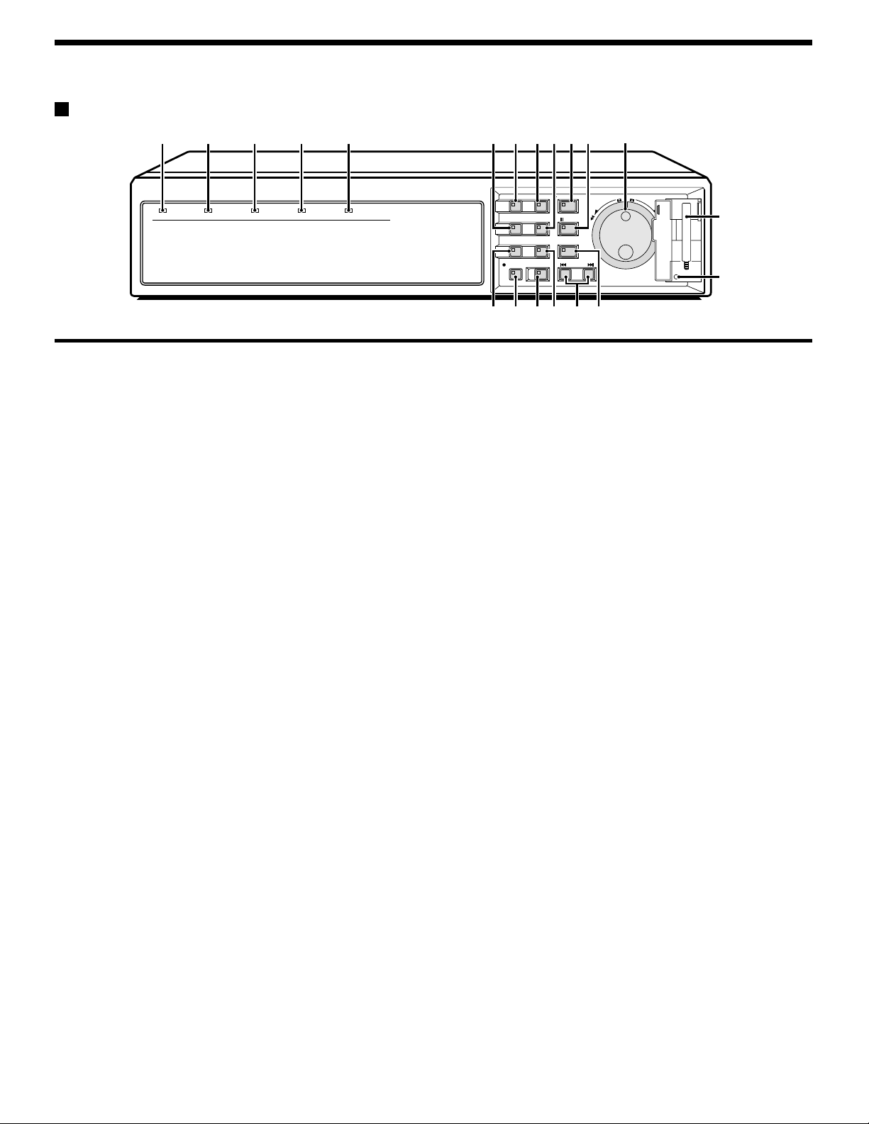
Front panel
1234 5 786FGJK N
POWER indicator
1
POWER FULL
ALARM FULL
LOCK ALARM
Flashes quickly (4 Hz) for a hard disk error and flashes slowly for a
fan error. Illuminates when the power cord plug is inserted into a wall
outlet. Flashes when there is a problem with the hard disk or fan.
FULL indicator
2
Flashes when overwriting is set to off and the remaining space in the
normal recording area of the hard disk drops to 1%*. (* This can be
changed using the menu settings.)
ALARM FULL indicator
3
Flashes when overwriting is set to off and the remaining space in the
alarm recording area of the hard disk drops to 1%*. (* This can be
changed using the menu settings.)
LOCK indicator
4
Illuminates when the security lock is engaged and operations are locked.
If a button is pressed while the lock is engaged, the buzzer sounds
and the indicator illuminates.
ALARM indicator
5
Illuminates during pre-alarm recording.
Flashes during alarm recording.
MENU button and indicator
6
Used to display the menu screens (setting screens).
ZOOM button and indicator
7
Used to display the zoom screen during playback.
The indicator illuminates when the zoom screen is displayed.
This does not operate when a multiplexer is connected.
CHANNEL button and indicator
8
If the digital video recorder is connected to a Sanyo multiplexer that
allows decoding of channel information (camera numbers), channels
can be specified so that only those channels are played back. The
indicator illuminates during playback. The CHANNEL button can only
be used during still mode.
REC/STOP button and indicator
9
Use to start normal recording.
The indicator illuminates during recording.
If the button is pressed for 2 seconds or more during recording,
recording stops and the indicator switches off.
EXIT/OSD button and indicator
F
•
When a menu screen is displayed
The main menu or sub-menu is exited.
•
During recording or playback
When the button is pressed during recording or playback,
superimposed information such as time and date and alarm
status changes in the following order:
Displayed at top-left → Displayed at bottom-left → Displayed at
top-right → Displayed at bottom-right → Off.
The indicator illuminates while information is displayed.
English
MENU
ZOOM
CHANNEL
REC/STOP
EXIT/OSD
PLAY/STOP
SEARCH
FRAME/FIELD
STILL
COPY
SHUTTLE HOLD
TIMER ALARM
SHUTTLE
E
N
JOG
R
T
A
E
L
C
E
R
O
P
9IHML
SEARCH FRAME/FIELD button and indicator
G
•
During recording or when stopped
When the button is pressed during recording or when the digital
video recorder is stopped, the indicator illuminates and search
playback is possible.
•
During playback
When the button is pressed during playback, the indicator
illuminates and the mode change to frame/field playback mode.
COPY button and indicator
H
Used to copy images to the archive area of the hard disk or to a
CompactFlash card or microdrive.
The indicator illuminates during copying.
TIMER button and indicator
I
When the button is pressed when recording is stopped, the digital
video recorder switches to timer recording standby mode, and when
the setting time is reached, timer recording starts.
PLAY/STOP button and indicator
J
When the button is pressed, the indicator illuminates and playback of
images in the normal recording area starts.
If pressed during playback, playback stops.
STILL button and indicator
K
When this button is pressed during playback, the indicator illuminates
and playback pauses. If it is pressed again, playback resumes.
SHUTTLE HOLD button and indicator
L
This locks the speed for playback and frame advance.
The indicator illuminates while locked.
ALARM buttons (û ALARM ù)
M
When these buttons are pressed during playback, playback skips to
the previous or next alarm recording.
Jog (inner) and shuttle (outer) dials
N
•
During playback
The jog dial changes the playback speed.
The shuttle dial fast-forwards and rewinds.
•
Menu screens
The jog dial moves the cursor and changes settings.
The shuttle dial accepts settings.
CompactFlash card slot
O
Insert a CompactFlash card or microdrive here.
MENU RESET button
P
Reinitializes menu settings.
5
Page 7
PART NAMES
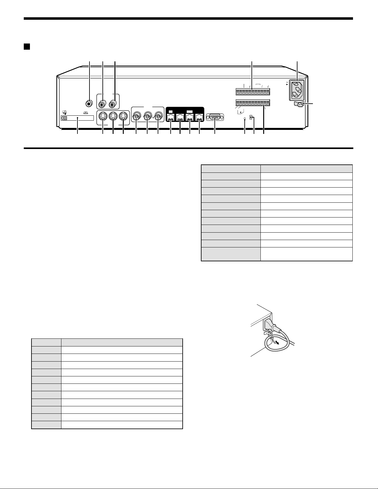
Rear panel
EJECT
PC Card SLOT
234 O P
ALARM
CLOCK
ADJUST
RESET
NON REC
OUT
ALARM
ALARM
OUT
IN
C
C
AUDIO
MIC
IN
IN
OUTIN
LOOP OUT
S-VIDEO
VIDEO
LOOP OUT
IN
OUT
OUT
DIGITAL
OUT
SUB IN
IN
SUB OUT
RS232C
RS485
NCCC
B
REMOTE
AONC
RS485
TERMINATE
ALL
RESET
OFF
OUT
WARNING
FULLOUTIN
SW OUT
AC IN
ALARM
FULL
CCNC
NMLKJIHGF987651
Q
PC card slot
1
Connect a recommended network card or SCSI card here.
Note: The PC card slot is for 16 bit 5 V cards only.
Do not use 32 bit card bus types of card, as they may damage
the PC card slot of the digital video recorder.
MIC IN terminal
2
AUDIO IN terminal
3
AUDIO OUT terminal
4
S-VIDEO IN terminal
5
S-VIDEO LOOP OUT terminal
6
S-VIDEO OUT terminal
7
VIDEO IN terminal
8
Images being input to the S-VIDEO IN terminal take priority.
VIDEO LOOP OUT terminal
9
VIDEO OUT terminal
F
DIGITAL VIDEO IN terminal
G
DIGITAL VIDEO OUT terminal
H
DIGITAL VIDEO SUB IN terminal
I
DIGITAL VIDEO SUB OUT terminal
J
RS-232C terminal
K
ALL RESET button
L
RS-485 termination switch
M
Control connector
N
Pin Signal
C Ground
A RS-485 connector*
B RS-485 connector*
C Ground
REMOTE Remote control input
C Ground
NC Spare
NC Spare
C Ground
SW OUT Switching output
C Ground
Alarm connector
O
Pin Signal
C Ground
ALARM IN Alarm input
ALARM RESET Alarm reset input
ALARM OUT Alarm output
NON REC OUT Non-rec output
C Ground
CLOCK ADJUST IN Clock sync input (See page 43.)
CLOCK ADJUST OUT Clock sync output (See page 43.)
WARNING OUT HDD error warning output
FULL HDD space warning output
ALARM OUT Alarm recording area space warning
output
AC power socket (AC IN~)
P
Securely insert the accessory power cord here.
Power cord holder
Q
Secure the power cord to the holder using the accessory cord tie as
shown in the illustration.
* Used for twisted-pair cable connection.
6
English
Page 8
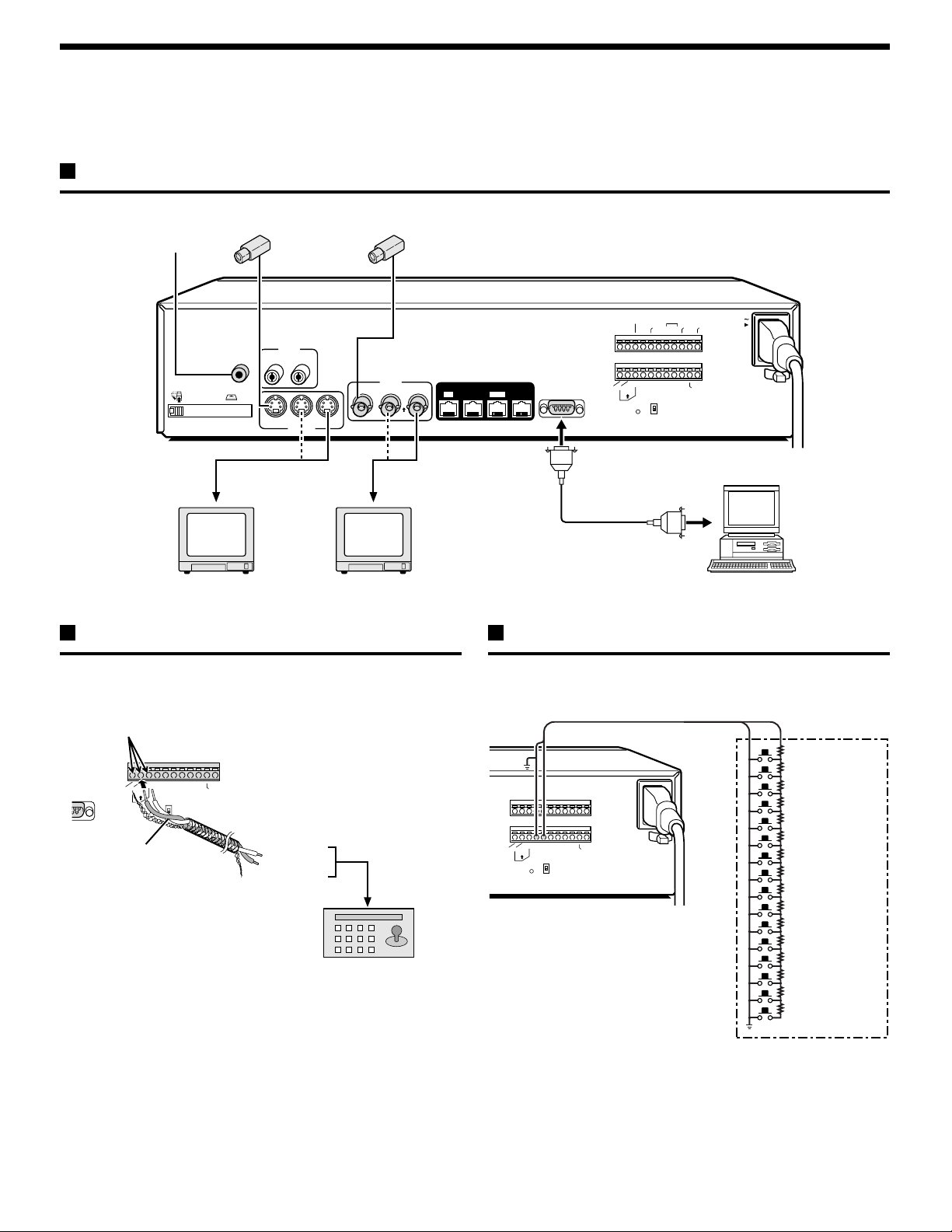
CONNECTIONS
Be sure to carefully read the Instruction Manuals for all equipment being connected to the digital video recorder.
If the connections are incorrect, smoke or operating malfunctions may result.
Basic connections
Video camera (sold separately)
Microphone input
ALARM
RESET
NON REC
ALARM
ALARM
OUT
IN
C
C
AUDIO
AUDIO
MIC
EJECT
IN
PC Card SLOT
IN
OUTIN
LOOP OUT
S-VIDEO
OUT
IN
IN
VIDEO
LOOP OUT
OUT
B
REMOTE
RS485
AONC
RS485
TERMINATE
ALL
RESET
OFF
DIGITAL
SUB OUT
OUT
SUB IN
IN
RS232C
CLOCK
ADJUST
OUT
NCCC
OUT
WARNING
FULLOUTIN
SW OUT
AC IN
ALARM
FULL
CCNC
S-VIDEO IN
connector
TV monitor
(sold separately)
(sold separately)
VIDEO IN
connector
TV monitor
System control connections
Use a twisted-pair cable (sold separately) to connect a system controller
to control terminals A, B and C (ground) of the digital video recorder.
Connect signal A to signal A and signal B to signal B.
Push and insert cables
2C
AONC
RS485
Twisted-pair cable
B
ALL
RESET
REMOTE
RS485
TERMINATE
OFF
CCNCNCCC
S
W
O
U
T
Ground
To signal B
To signal A
RS-485 connector
System controller (sold separately)
Computer
Connecting a remote control circuit
If a remote control circuit is constructed as shown in the illustration and
connected to the REMOTE control input terminals of the control
connector, the digitao video recorder can be operated by remote control.
220Ω
SW 1: REC STOP
220Ω
SW 2: PLAY STOP
300Ω
SW 3: PAUSE
360Ω
SW 4: SEARCH
470Ω
SW 5: CHANNEL
680Ω
SW 6: PLAY
820Ω
SW 7: REC
1.2kΩ
SW 8: MENU
1.8kΩ
SW 9 : EXIT/OSD
2.2kΩ
SW 10 : JOG j
3.3kΩ
SW 11 : JOG l
4.7kΩ
SW 12 : SHUTTLE c
7.5kΩ
SW 13 : SHUTTLE d
13kΩ
SW 14 : ZOOM
27kΩ
SW 15 : COPY
68kΩ
SW 16 : TIMER
RS485
B
AONC
TERMINATE
ALL
RESET
REMOTE
RS485
OFF
SW OUT
CCNCNCCC
SW: Switch
Note:
The remote control cable should
be no more than 5 m long.
English
7
Page 9
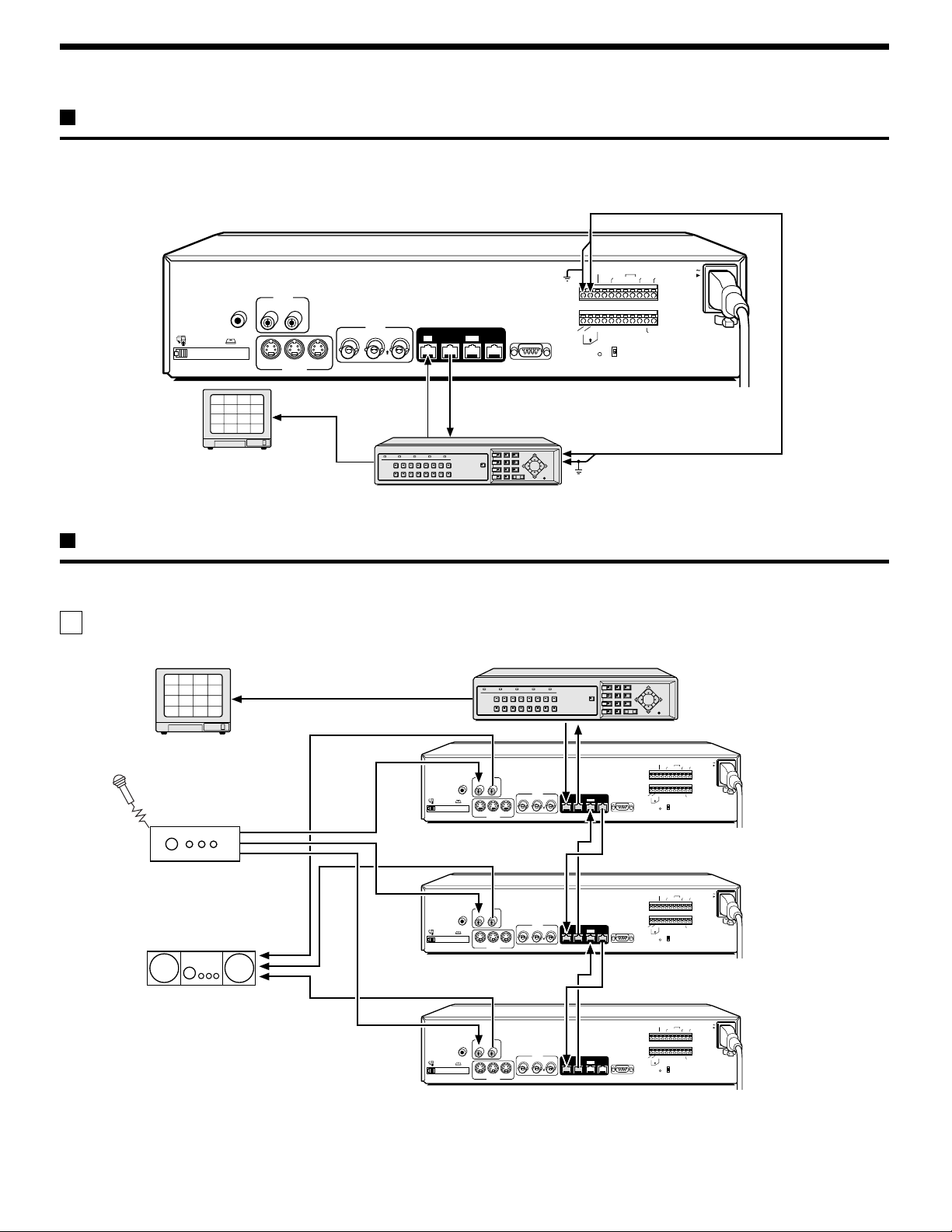
CONNECTIONS
Digital multiplexer connections
Connect to a multiplexer (MPX-CD163 or CD93) that allows digital connections.
AUDIO
MIC
EJECT
IN
PC Card SLOT
IN
OUTIN
LOOP OUT
S-VIDEO
S-VIDEO
VIDEO
LOOP OUT
IN
OUT
DIGITAL
OUT
SUB IN
IN
OUT
SUB OUT
RS232C
(When necessary)
Alarm input
ALARM
CLOCK
ADJUST
RS485
C
ALARM
C
AONC
RESET
ALARM
OUT
IN
IN
B
ALL
RESET
NON REC
REMOTE
RS485
TERMINATE
OFF
OUT
OUT
ALARM
WARNING
FULLOUTIN
C
NCCC
CCNC
SW OUT
AC IN
FULL
2
1
3
4
6
5
7
8
10
9
11
12
14
13
15
16
✱ STP (Shielded Twisted Pair) Cable
(straight-type CAT-5, 3 m or less)
DIGITAL INDIGITAL OUT
TV monitor (sold separately)
Multiplexer (sold separately)
Dgital series connections
Up to three digital video recorders can be connected digitally for recording images in series.
A Digital connection of multiplexers in series
Multiplexer (sold separately)
2
1
3
4
6
5
7
8
10
9
11
12
14
13
15
16
TV monitor
(sold separately)
EJECT
PC Card SLOT
AUDIO
MIC
IN
OUTIN
VIDEO
LOOP OUT
IN
LOOP OUT
IN
S-VIDEO
OUT
OUT
Alarm output
Ground (C)
DIGITAL
SUB OUT
OUT
SUB IN
IN
Digital video recorder (main)
ALARM
CLOCK
AC IN
ADJUST
RESET
OUT
OUT
NON REC
ALARM
WARNING
ALARM
ALARM
FULL
OUT
IN
FULLOUTIN
C
C
NCCC
B
REMOTE
CCNC
SW OUT
AONC
RS232C
RS485
TERMINATE
ALL
RS485
RESET
OFF
Amplifier
(sold separately)
Amplifier
(sold separately)
AUDIO
MIC
IN
OUTIN
VIDEO
LOOP OUT
IN
OUT
EJECT
PC Card SLOT
IN
LOOP OUT
OUT
S-VIDEO
AUDIO
MIC
IN
OUTIN
EJECT
PC Card SLOT
IN
LOOP OUT
OUT
S-VIDEO
IN
VIDEO
LOOP OUT
IN
OUT
IN
Digital video recorder (sub 1)
ALARM
CLOCK
ADJUST
RESET
OUT
OUT
NON REC
WARNING
ALARM
ALARM
OUT
IN
FULLOUTIN
C
C
NCCC
B
REMOTE
CCNC
SW OUT
DIGITAL
SUB OUT
OUT
SUB IN
AONC
RS232C
RS485
TERMINATE
ALL
RS485
RESET
OFF
Digital video recorder (sub 2)
ALARM
CLOCK
ADJUST
RESET
OUT
OUT
NON REC
WARNING
ALARM
ALARM
OUT
IN
FULLOUTIN
C
C
NCCC
B
REMOTE
CCNC
SW OUT
DIGITAL
SUB OUT
OUT
SUB IN
AONC
RS232C
RS485
TERMINATE
ALL
RS485
RESET
OFF
AC IN
ALARM
FULL
AC IN
ALARM
FULL
Note: For digital connections a shielded type LAN cable (Shielded Twisted Pair) must be used.
When digital video recorders are connected digitally in series, the digital input and output terminals can be used to transmit video signals,
control signals and switching signals. However audio signals cannot be transmitted in the same way, so if audio signals also need to be
recorded, connect the audio input terminals via an amplifier as shown in the connection diagram.
8
English
Page 10
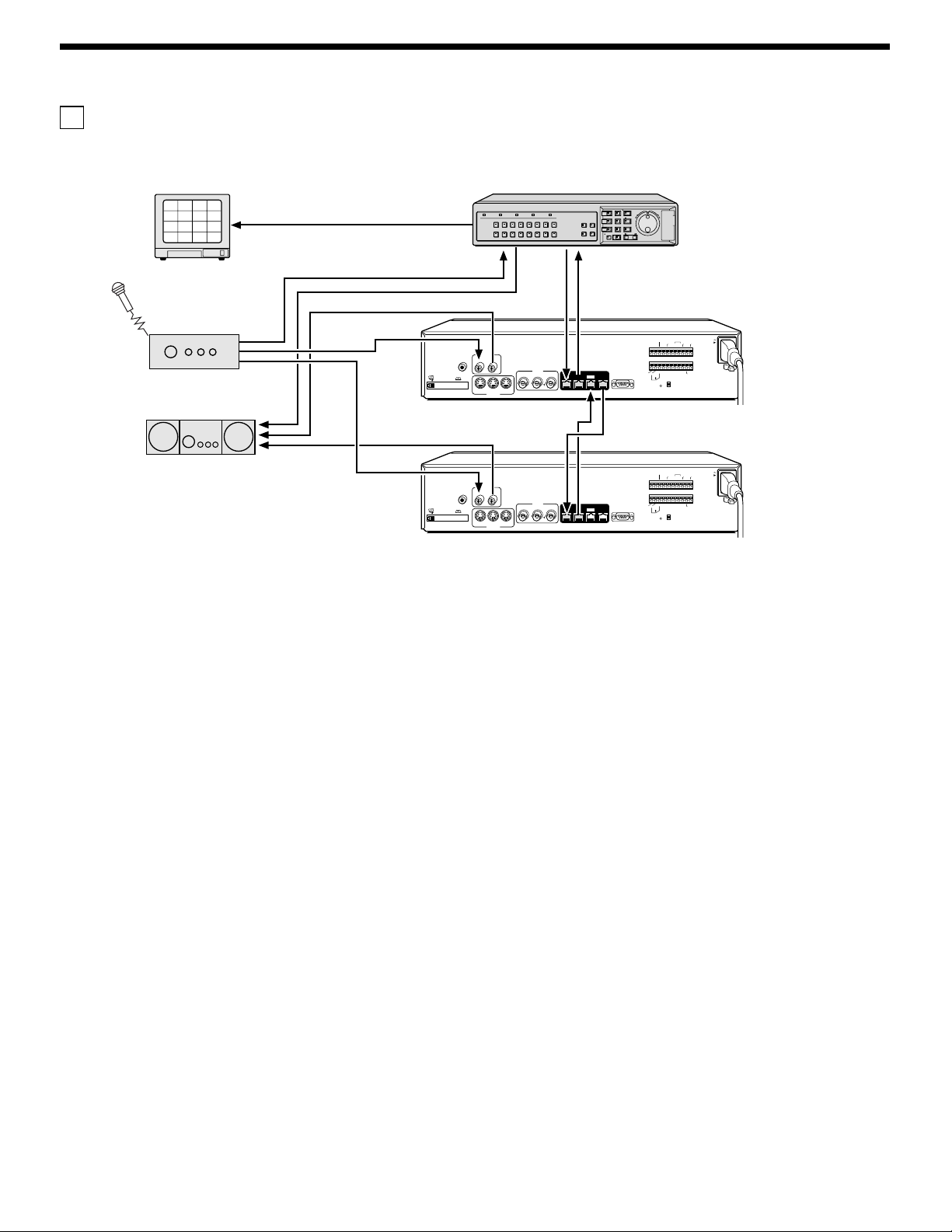
CONNECTIONS
B Digital connection of digital video recorders with multiplexer function in series
Digital video recorders
with multiplexer function
(sold separately)
2
1
3
4
6
5
7
8
10
9
11
12
14
13
15
16
TV monitor
(sold separately)
Amplifier
(sold separately)
Amplifier
(sold separately)
POWER FULL
AUDIO
MIC
IN
OUTIN
EJECT
PC Card SLOT
IN
LOOP OUT
S-VIDEO
(sold separately)
AUDIO
MIC
IN
OUTIN
EJECT
PC Card SLOT
LOOP OUT
IN
S-VIDEO
(sold separately)
ALARM FULL
LOCK ALARM
12345678
910111213141516
VIDEO
OUT
LOOP OUT
IN
OUT
VIDEO
OUT
LOOP OUT
IN
OUT
MULTI
QUAD
PLUS
MON2
DIGITAL
SUB OUT
OUT
SUB IN
IN
DIGITAL
SUB OUT
OUT
SUB IN
IN
SHUTTLE
PLAY/STOP
MENU
EXIT/OSD
E
N
R
JOG
T
A
E
E
L
R
C
SEARCH
STILL
ZOOM
SEQUENCE
COPY
SHUTTLE LOCK
ALARM
TIMER
REC/STOP
Digital video recorder (sub 1)
ALARM
CLOCK
AC IN
ADJUST
RESET
OUT
OUT
NON REC
ALARM
WARNING
ALARM
ALARM
FULL
OUT
IN
FULLOUTIN
C
C
NCCC
B
REMOTE
CCNC
SW OUT
AONC
RS232C
RS485
TERMINATE
ALL
RS485
RESET
OFF
Digital video recorder (sub 2)
ALARM
CLOCK
AC IN
ADJUST
RESET
OUT
OUT
NON REC
ALARM
WARNING
ALARM
ALARM
FULL
OUT
IN
FULLOUTIN
C
C
NCCC
B
REMOTE
CCNC
SW OUT
AONC
RS232C
RS485
TERMINATE
ALL
RS485
RESET
OFF
English
9
Page 11
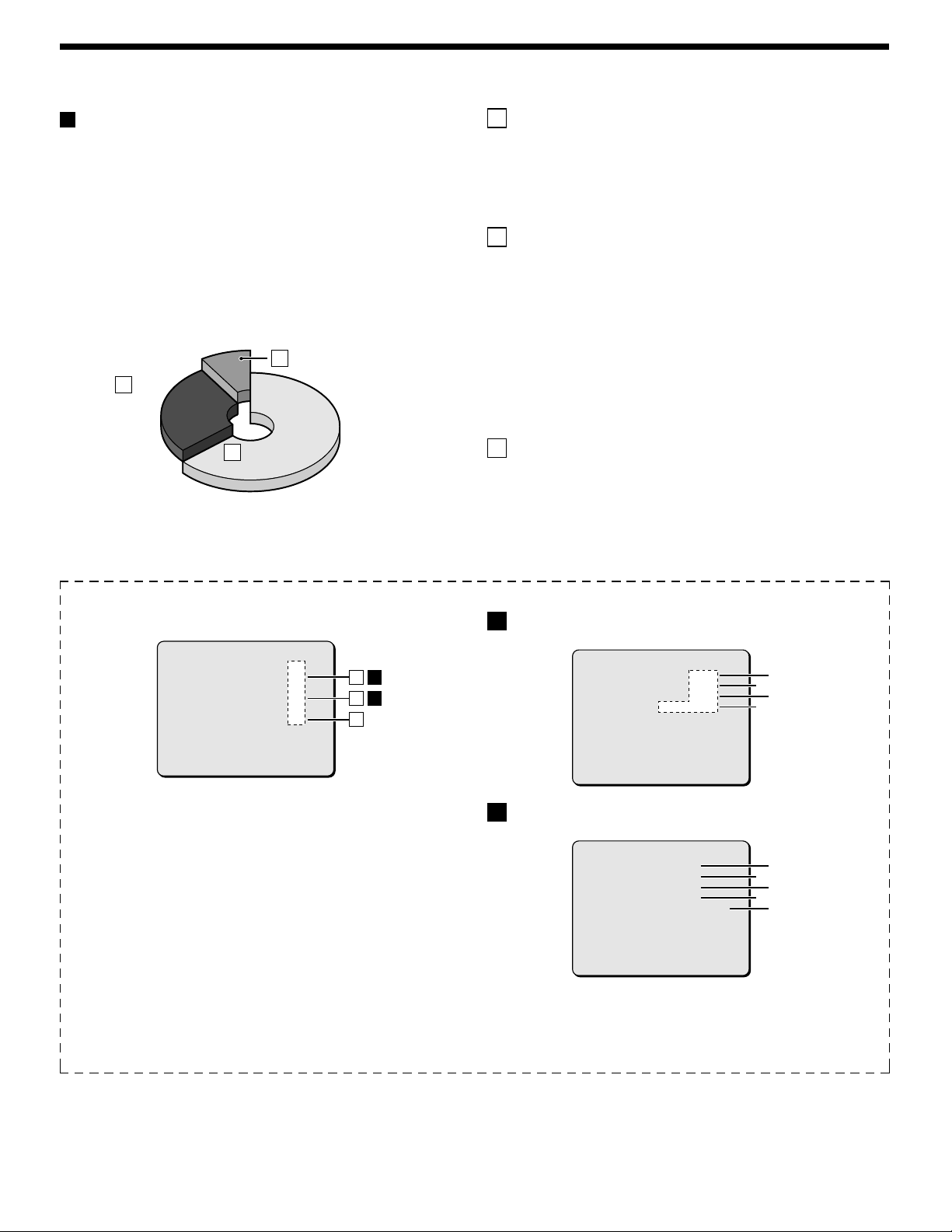
BUILT-IN HARD DISK
Normal recording area
Hard disk
Recording areas
The recording areas on the hard disk (normal recording area: 80%,
alarm recording area: 19%, archive area: 1%) are established
automatically when the power for the digital video recorder is turned on.
Images are recorded in the normal recording area when the REC/STOP
button is pressed, and they are recorded in the alarm recording area
when an alarm occurs. This is called the default condition, and the
following detailed settings can be confirmed in the sections on
“RECORDING IMAGES IN THE NORMAL RECORDING AREA” and
“RECORDING IMAGES IN THE ALARM RECORDING AREA” which
are explained later. Furthermore, settings such as the recording areas
and picture quality can be changed using the menu screens.
Archive areaC
80%
80%
Alarm
Alarm
B
recording
recording
area
area
1%
1%
19%
19%
Normal recording areaA
Normal recording area
Hard disk recording areas
A Normal recording area
When the REC/STOP button is pressed while monitoring is in
•
progress, images are recorded in the normal recording area.
When start and end times are entered for each day of the week and
•
are then enabled, timer recording is automatically carried out in the
normal recording area between the times that have been set.
B Alarm recording area
ALARM REC MODE SET menu settings are required.
Alarm recording is enabled when ALARM RECORDING is set. When
•
a suspicious person is detected by the switch or motion sensor that
is connected to the alarm input terminal, an alarm is recorded in the
alarm recording area.
Pre-alarm recording is enabled when PRE-ALARM RECORDING is
•
set. Pre-alarm recording repeatedly records the same images as for
normal recording in the alarm recording area, and overwrites these
images after the set time interval, until an alarm is detected. When
pre-alarm recording is set, the image immediately before an alarm
occurred can be recorded.
C Archive area
This is the area for copying important images from the normal recording
area and the alarm recording area. The size of the archive area can be
set to a maximum of 10 GB (12.5% of total capacity when using an
80-GB hard disk, 6.25% of total capacity when using an 160-GB hard
disk) by changing the size of the normal recording area or the alarm
recording area.
Menu screen (initial setting)
This can be displayed by pressing the MENU button.
<RECORDING AREA SET>
TOTAL CAPACITY : 80GB
NORMAL RECORDING AREA : 80 %
AREA FULL RESET ->
ALARM RECORDING AREA : 19 %
AREA FULL RESET ->
ARCHIVE AREA : 1 %
AREA FULL RESET ->
CAUTION : WHEN THE AREA SETTING IS CHANGED.
THE WHOLE AREA WILL BE INITIALIZED !
1
Picture quality: ENHANCED
Picture quality can be selected from five options.
The recording speed changes in accordance with the picture
quality selected.
2
Recording method: Can be set to FRAME or FIELD.
The recording speed changes in accordance with the method
selected.
3
Audio recording: Can be set to ON or OFF.
4
Recording speed: Shows the recording interval and the
recording time.
Refer to the recording speed table for further details.
5
Alarm recording setting: Can be set to ON or OFF.
When alarm recordings are to be made, select a setting such as
MODE1 for the OFF setting. The recording speed and alarm
duration will be displayed
ABA
B
C
A
Setting screen for normal recording area picture quality,
recording speed, etc.
<NORMAL REC MODE SET>
PICTURE QUALITY : ENHANCED
FRAME/FIELD RECORDING : FIELD
AUDIO RECORDING : OFF
REC CYCLE : 0.10SEC ( 54H)
B
Setting screen for alarm recording area picture quality,
recording speed, etc.
<ALARM REC MODE SET>
PICTURE QUALITY : ENHANCED
FRAME/FIELD RECORDING : FIELD
AUDIO RECORDING : OFF
ALARM RECORDING : OFF
REC CYCLE : 0.10SEC. DURATION: 1SEC
PRE-ALARM RECORDING :
REC CYCLE :
=> (46400 ALARMS CAN BE RECORDED)
ALARM TRIGGER : ALARM
MOTION SENSOR ->
¤¤¤
¤¤¤
SEC. DURATION:
¤¤¤
2
4
2
5
1
3
1
3
4
10
English
Page 12
BUILT-IN HARD DISK
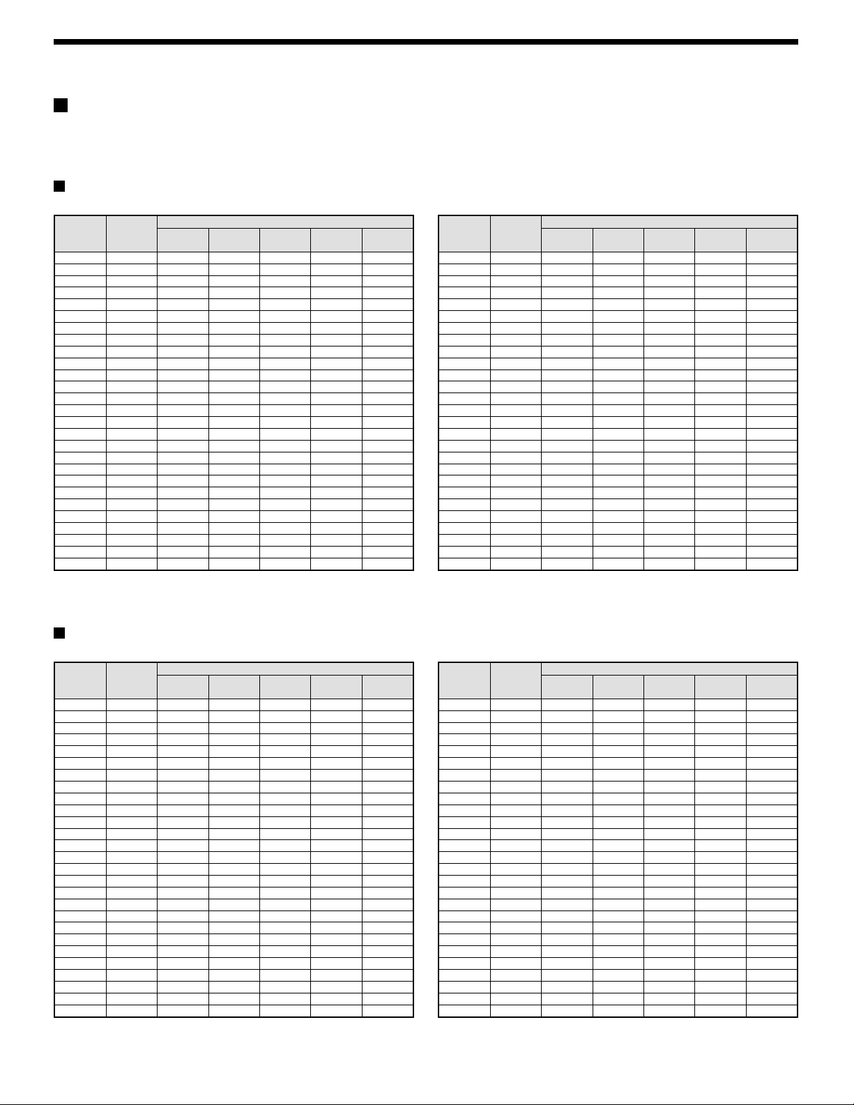
Recording speed tables (The recording time may vary depending on the images being recorded.)
These recording speed tables show the recording times for various picture quality and frame/field settings when recording in the normal recording area
of the hard disk (80 GB). They do not include audio recording settings.
The recording times for the normal recording area and the alarm recording area represent the recording time values given in the recording speed tables,
multiplied by the percentages for the normal recording area and alarm recording area that have been set using the recording area setting menu commands.
When recording with an 80-GB hard disk at 100% capacity
Field recording
Recording
(field/sec)
60.00 0.02 21H 15H 11H 8H 6H
30.00 0.03 42H 30H 22H 16H 12H
20.00 0.05 63H 45H 33H 24H 18H
15.00 0.07 85H 60H 45H 32H 24H
10.00 0.10 127H 90H 67H 49H 37H
Recording
Rate
Cycle (SEC)
7.50 0.13 170H 120H 90H 65H 49H
6.00 0.17 212H 150H 113H 82H 62H
5.00 0.20 255H 180H 135H 98H 74H
4.29 0.23 297H 210H 158H 115H 87H
3.75 0.27 340H 241H 180H 131H 99H
3.33 0.30 382H 271H 203H 147H 112H
3.00 0.33 425H 301H 226H 164H 124H
2.73 0.37 468H 331H 248H 180H 137H
2.31 0.43 553H 391H 293H 213H 162H
2.00 0.50 638H 452H 339H 246H 187H
1.67 0.60 765H 542H 406H 295H 224H
1.43 0.70 893H 632H 474H 345H 261H
1.25 0.80 1021H 723H 542H 394H 299H
1.11 0.90 1148H 813H 610H 443H 336H
1.00 1 1276H 904H 678H 493H 374H
0.50 2 2553H 1808H 1356H 986H 748H
0.33 3 3829H 2712H 2034H 1479H 1122H
0.25 4 5106H 3616H 2712H 1972H 1496H
0.20 5 6382H 4521H 3390H 2466H 1870H
0.10 10 12765H 9042H 6781H 4932H 3741H
0.05 20 25531H 18084H 13563H 9864H 7483H
0.03 30 38296H 27126H 20345H 14796H 11224H
BASIC NORMAL ENHANCED FINE SUPER FINE
RECORDING TIME
The tables below are recording time tables provided for reference if the total capacity of the hard disk has been increased to 160 GB. (Contact the
place of purchase for details on increasing the capacity of the hard disk.)
Frame recording
Recording
(frame/sec)
30.00 0.03 21H 15H 11H 8H 6H
15.00 0.07 42H 30H 22H 16H 12H
10.00 0.10 63H 45H 33H 24H 18H
Recording
Rate
Cycle (SEC)
7.50 0.13 85H 60H 45H 32H 24H
5.00 0.20 127H 90H 67H 49H 37H
3.75 0.27 170H 120H 90H 65H 49H
3.00 0.33 212H 150H 113H 82H 62H
2.50 0.40 255H 180H 135H 98H 74H
2.14 0.47 297H 210H 158H 115H 87H
1.88 0.53 340H 241H 180H 131H 99H
1.67 0.60 382H 271H 203H 147H 112H
1.50 0.67 425H 301H 226H 164H 124H
1.36 0.73 468H 331H 248H 180H 137H
1.15 0.87 553H 391H 293H 213H 162H
1.00 1.00 638H 452H 339H 246H 187H
0.83 1.20 765H 542H 406H 295H 224H
0.71 1.40 893H 632H 474H 345H 261H
0.63 1.60 1021H 723H 542H 394H 299H
0.56 1.80 1148H 813H 610H 443H 336H
0.50 2 1276H 904H 678H 493H 374H
0.25 4 2553H 1808H 1356H 986H 748H
0.17 6 3829H 2712H 2034H 1479H 1122H
0.13 8 5106H 3616H 2712H 1972H 1496H
0.10 10 6382H 4521H 3390H 2466H 1870H
0.05 20 12765H 9042H 6781H 4932H 3741H
0.03 40 25531H 18084H 13563H 9864H 7483H
0.02 60 38296H 27126H 20345H 14796H 11224H
BASIC NORMAL ENHANCED FINE SUPER FINE
RECORDING TIME
When recording with a 160-GB hard disk at 100% capacity
Field recording
Recording
(field/sec)
60.00 0.02 42H 30H 22H 16H 12H
30.00 0.03 85H 60H 45H 32H 24H
20.00 0.05 127H 90H 67H 49H 37H
15.00 0.07 170H 120H 90H 65H 49H
10.00 0.10 255H 180H 135H 98H 74H
Recording
Rate
Cycle (SEC)
7.50 0.13 340H 241H 180H 131H 99H
6.00 0.17 425H 301H 226H 164H 124H
5.00 0.20 510H 361H 271H 197H 149H
4.29 0.23 595H 421H 316H 230H 174H
3.75 0.27 680H 482H 361H 263H 199H
3.33 0.30 765H 542H 406H 295H 224H
3.00 0.33 851H 602H 452H 328H 249H
2.73 0.37 936H 663H 497H 361H 274H
2.31 0.43 1106H 783H 587H 427H 324H
2.00 0.50 1276H 904H 678H 493H 374H
1.67 0.60 1531H 1085H 813H 591H 448H
1.43 0.70 1787H 1265H 949H 690H 523H
1.25 0.80 2042H 1446H 1085H 789H 598H
1.11 0.90 2297H 1627H 1220H 887H 673H
1.00 1 2553H 1808H 1356H 986H 748H
0.50 2 5106H 3616H 2712H 1972H 1496H
0.33 3 7659H 5425H 4069H 2959H 2244H
0.25 4 10212H 7233H 5425H 3945H 2993H
0.20 5 12765H 9042H 6781H 4932H 3741H
0.10 10 25531H 18084H 13563H 9864H 7483H
0.05 20 51062H 36168H 27126H 19728H 14966H
0.03 30 76593H 54253H 40690H 29592H 22449H
BASIC NORMAL ENHANCED FINE SUPER FINE
Reference: 24H = 1 day, 168H = 1 week, 720H = 1 month, 8760H = 1 year
RECORDING TIME
Frame recording
Recording
(frame/sec)
30.00 0.03 42H 30H 22H 16H 12H
15.00 0.07 85H 60H 45H 32H 24H
10.00 0.10 127H 90H 67H 49H 37H
Recording
Rate
Cycle (SEC)
7.50 0.13 170H 120H 90H 65H 49H
5.00 0.20 255H 180H 135H 98H 74H
3.75 0.27 340H 241H 180H 131H 99H
3.00 0.33 425H 301H 226H 164H 124H
2.50 0.40 510H 361H 271H 197H 149H
2.14 0.47 595H 421H 316H 230H 174H
1.88 0.53 680H 482H 361H 263H 199H
1.67 0.60 765H 542H 406H 295H 224H
1.50 0.67 851H 602H 452H 328H 249H
1.36 0.73 936H 663H 497H 361H 274H
1.15 0.87 1106H 783H 587H 427H 324H
1.00 1.00 1276H 904H 678H 493H 374H
0.83 1.20 1531H 1085H 813H 591H 448H
0.71 1.40 1787H 1265H 949H 690H 523H
0.63 1.60 2042H 1446H 1085H 789H 598H
0.56 1.80 2297H 1627H 1220H 887H 673H
0.50 2 2553H 1808H 1356H 986H 748H
0.25 4 5106H 3616H 2712H 1972H 1496H
0.17 6 7659H 5425H 4069H 2959H 2244H
0.13 8 10212H 7233H 5425H 3945H 2993H
0.10 10 12765H 9042H 6781H 4932H 3741H
0.05 20 25531H 18084H 13563H 9864H 7483H
0.03 40 51062H 36168H 27126H 19728H 14966H
0.02 60 76593H 54253H 40690H 29592H 22449H
BASIC NORMAL ENHANCED FINE SUPER FINE
RECORDING TIME
English
11
Page 13

BUILT-IN HARD DISK
Pre-alarm recording time
This table shows the recording times for pre-alarm recording. Refer to this table when setting pre-alarm recording. (See page 18.)
Recording
(field/sec)
60.00 0.02
30.00 0.03
20.00 0.05
15.00 0.07
10.00 0.10
Recording
Rate
Cycle (SEC)
7.50 0.13
6.00 0.17
5.00 0.20
4.29 0.23
3.75 0.27
3.33 0.30
3.00 0.33
2.73 0.37
2.31 0.43
2.00 0.50
1.67 0.60
1.43 0.70
1.25 0.80
1.11 0.90
1.00 1
2s (2s) 3s (3s) 5s (5s) 10s (10s) 20s (20s) 40s (40s) 60s (1m) 120s (2m) 180s (3m) 240s (4m) 300s (5m) 600s (10m) 900s (15m)
mmmmmmmmmmmmm
mmmmmmmmmmmm
mmmmmmmmmmm
mmmmmmmmmmm
: Default setting value, recording cycle: 0.1 second (10 FPS), Recording time: 1 minute
Recording time (Time display on menu screen; s: seconds, m: minutes))
mmmmmmmmmm
mmmmmmmmmm
mmmmmmmmmm
mmmmmmmmm
mmmmmmmmm
mmmmmmmmm
mmmmmmmmm
mmmmmmmmm
mmmmmmmmm
mmmmmmmm
mmmmmmmm
mmmmmmm
mmmmmmm
mmmmmmm
mmmmmmm
mmmmmmm
The alarm duration menu setting can only be set to a recording time that is possible with the current recording rate setting.
In addition, when setting the recording rate, it can only be set within the range allowed by the current alarm duration. For example, if the alarm duration
is set to 3 seconds, the recording rate can only be set to 0.02 seconds or 0.03 seconds.
If a slower recording rate is set, the setting will not be accepted until the alarm duration is changed.
12
English
Page 14

BUILT-IN HARD DISK
When the power for the digital video recorder is turned on, the operating display appears in the upper-left corner of the monitor screen. This operating
display shows information which is essential for operation, such as the date, time, picture quality and recording speed.
1623 45
4CH 100%
01-01-01 ALARM 0000
00:00:00 EN 0.10SEC
Operating display
01-01-01 ALARM 0000
00:00:00 EN 0.10SEC
DISK ERROR (1)
DISK ERROR (1)
9
78
Operating display
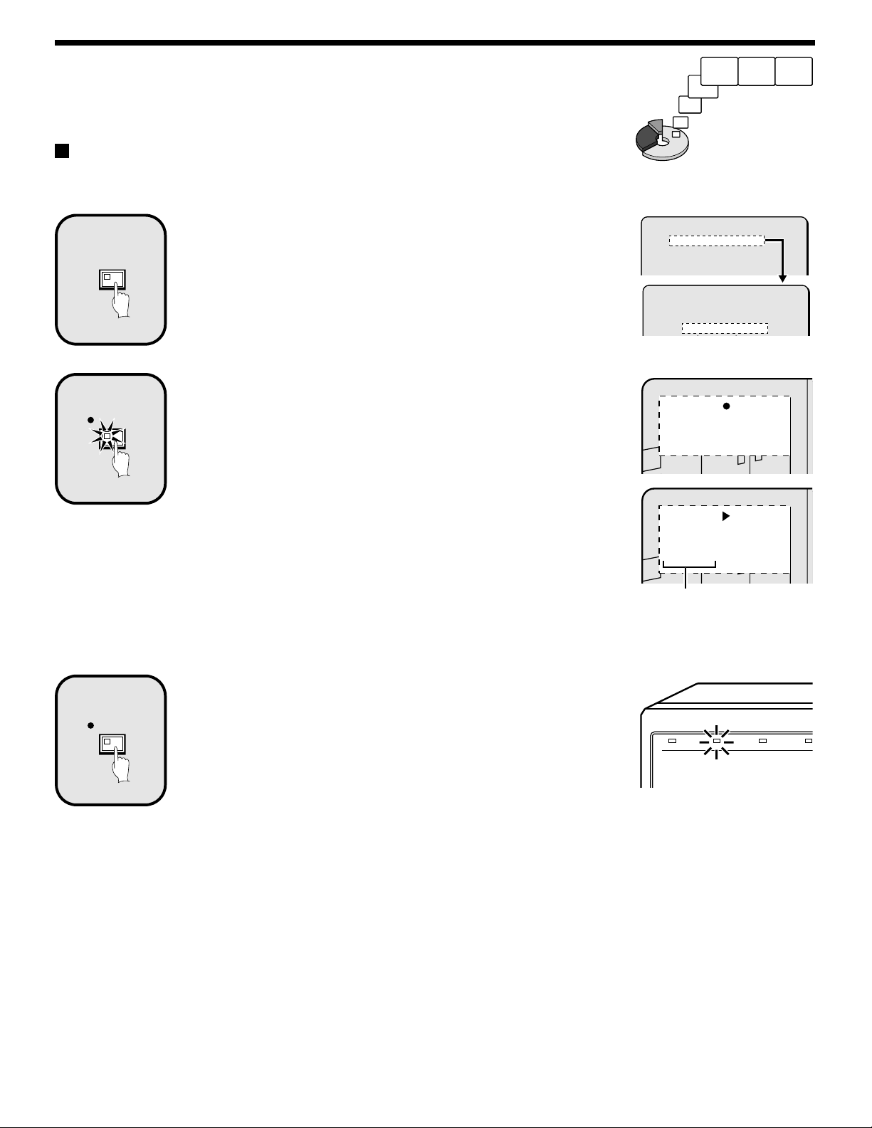
Insert the power cord into a wall outlet and turn on the power.
The POWER indicator illuminates, and after approximately 15 seconds, the EXIT/OSD indicator illuminates. The camera images appear on the
monitor, and the operating display appears in the top-left corner of the screen.
Note:
If the clock has not been set, the WARNING screen for setting the clock appears. If any operating button is pressed, the WARNING screen will
•
disappear, but recording and playback will not be possible until the clock has been set, so you will need to set the clock first. (See page 42.)
If you press the EXIT/OSD button repeatedly, you can change the display position for the operating display or make it disappear.
•
Camera number display
1
Connect the digital video recorder to a multiplexer that is capable of
decoding Sanyo’s channel information (camera number) and press
the CHANNEL button. The number of the specified camera appear in
the display during playback.
Date display
2
When the digital video recorder is first turned on, the date appears as
01-01-01 (month, day, year). Make sure that you use the menus to
set the correct date.
Operating symbol display
3
These symbols appear during recording and playback.
a : Recording e : Fast forward
c : Playback f : Rewind
d : Reverse playback h : Stopped
hc : Slow playback dh : Slow reverse playback
Note: If recording and playback are being carried out at the same
time, the playback symbol (c) appears.
Amount of recording area remaining
4
If overwriting has been disabled (OVERWRITE: OFF) in the normal
recording area or alarm recording area, the amount of space
remaining appears as a percentage. You can change the amount of
recording area remaining using the RECORDING CONDITIONS SET
menu item. (See page 48.)
Alarm display and alarm number display
5
When an alarm setting is made using the ALARM REC MODE SET
menu item, The following display appears in the alarm display.
However, the PRE display appears when pre-alarm recording has
been set. When an alarm occurs, the PRE is replaced by ALARM
and the number of alarms also appears. The alarm display shows the
cumulative number of alarms.
If ALARM RECORDING is set: ALARM appears.
•
ALARM flashes while an alarm is being recorded.
If PRE-ALARM RECORDING is set: PRE appears.
•
When playing images from the archive area: ARCHIV appears.
•
Time display
6
When the digital video recorder is first turned on, the time appears as
00:00:00, and the time starts counting after the date has been set.
The digital video recorder uses the date and time to control recording
and playback, so if the date and time have not been set, the correct
images cannot be retrieved. Make sure that you use the menus to
set the correct time.
Picture quality display
7
This shows the picture quality for images that are recorded on the
hard disk. The default setting is EN (Enhanced). The display
changes when the picture quality is changed using the NORMAL
REC MODE SET menu item.
BA: Basic
•
NO: Normal
•
EN: Enhanced
•
FI: Fine
•
SF: Super Fine
•
Recording speed display
8
This displays the recording speed for images that are recorded on
the hard disk. The default setting is 0.10 SEC (during field recording).
The display changes when the picture quality and recording method
are changed using the NORMAL REC MODE SET menu item.
Hard disk error display
9
This display appears if an error occurs with the hard disk.
DISK ERROR: This appears when two hard disks or an expansion
•
DISK ERROR (1): This appears when an error has occurred with
•
DISK ERROR (2): This appears when an error has occurred with
•
hard disk has been installed, and an error had
occurred with either one of the hard disks.
DISK 1 (MASTER).
DISK 2 (SLAVE).
English
Note: During recording with this unit, playing back, copying
and transferring pictures is possible. However,
because of the recording priority the response of the
other operations becomes slower.
13
Page 15
RECORDING IMAGES IN THE
NORMAL RECORDING AREA
Normal recording
Images can be recorded in the normal recording area while they are being monitored.
If the time has not been set, the digital video recorder cannot make recordings. Be sure to set the time. (See page 42.)
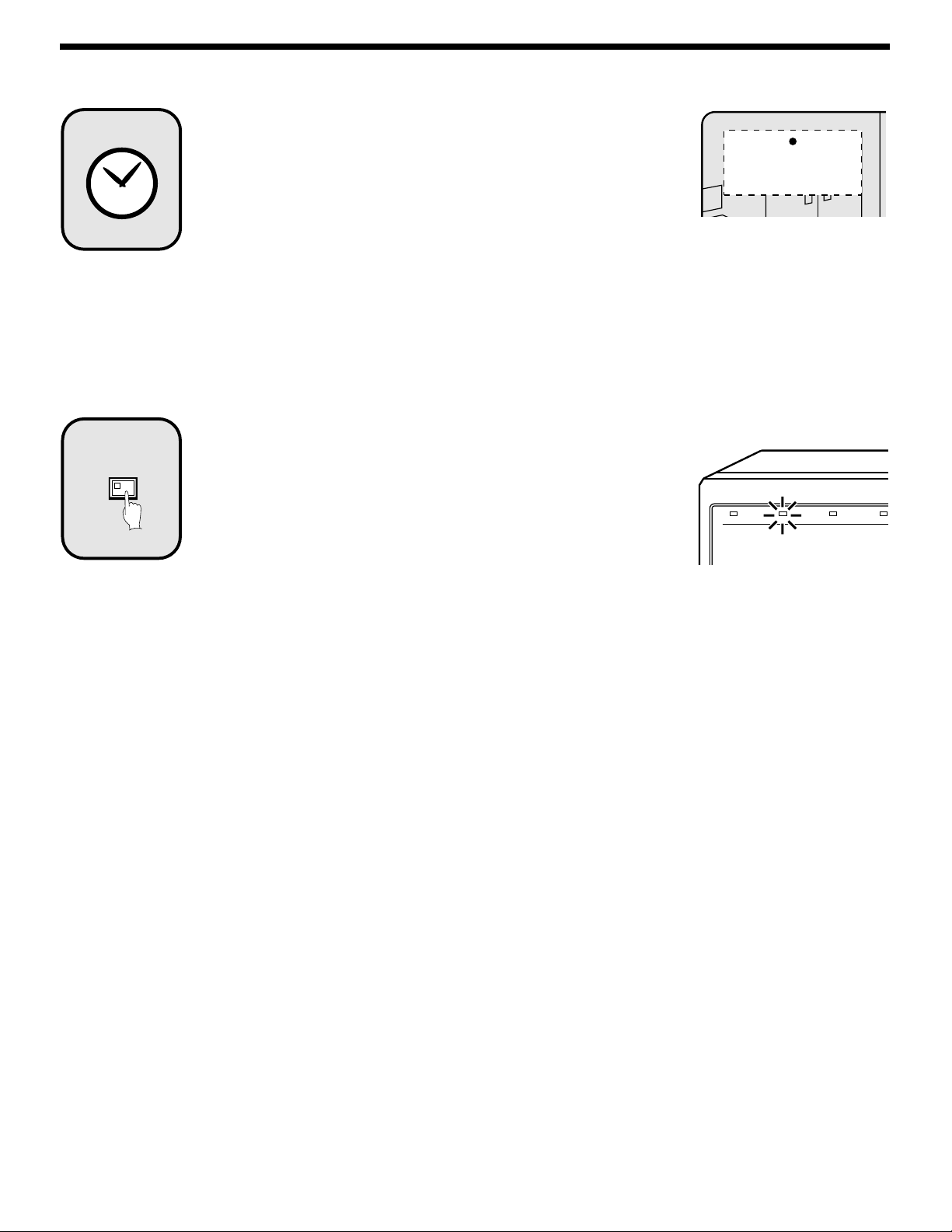
Setting the time
1
MENU
2
REC/STOP
Press the MENU button to display the LANGUAGE/CLOCK SET menu, and set
the date and time. After the setting has been made, press the EXIT/OSD button,
the date and time appear in the operating display. (See page 42.)
Press the REC/STOP button.
“a” appears in the operating display and the images being monitored are
recorded in the normal recording area. Recording onto the hard disk proceeds
automatically (default setting) according to the following settings. The settings
can be changed between long-period recording and high-quality recording in five
steps. (See page 49.)
Hard disk recording areas:
•
Normal recording area: 80%
Alarm recording area: 19%
Archive area: 1%
Picture quality: EN (Enhanced)
•
Recording method: Field
•
Recording speed: 0.10 seconds (54H)
•
Note: Playback is possible during recording. When the PLAY/STOP button is
pressed during recording, “c” appears in the operating display and
images are played back from the point where recording began. (See page
20.)
Monitored images
are recorded.
<MAIN MENU 1>
1.LANGUAGE/CLOCK SET ->
2.VIDEO INPUT SET ->
3.RECORDING AREA SET ->
4.RECORDING CONDITIONS SET ->
<LANGUAGE/LANGUE/IDIOMA>
ENGLISH
<CLOCK SET>
01-01-2001 MON 00:00:00
10-26-01
10:48:38 EN 0.10SEC
10-26-01
11:02:28 EN 0.10SEC
Recording start time
3
REC/STOP
Press and hold the REC/STOP button for 3 seconds or more.
The “a” in the operating display disappears and recording stops.
Note: When the remaining area in the normal recording area drops below the
set amount, the FULL indicator on the front panel flashes. If recording
continues under these conditions, the recording area becomes full and
recording stops. In the RECORDING AREA SET settings, carry out the
AREA FULL RESET operation for the normal recording area.
Recording will then be possible from the beginning again. (See page 48.)
POWER FULL
ALARM FULL
LOC
14
English
Page 16

RECORDING IMAGES IN THE NORMAL RECORDING AREA
Timer recording
The monitored images can be recorded automatically by setting start and end times for each day of the week.
1
2
MENU
TIMER
1 Setting the time
Press the MENU button to display the LANGUAGE/CLOCK SET menu, and set
the date and time. After the setting has been made, press the EXIT/OSD button,
the date and time appear in the operating display. (See page 42.)
2 Set the timer.
Press the MENU button to display the TIMER SET menu, and then set the start
and end times for timer recording. (See page 50.)
Then press the EXIT/OSD button.
Press the TIMER button.
The TIMER indicator illuminates and the digital video recorder switches to timer
recording standby mode.
Note:
If SET in the TIMER SET menu is not set to “ON”, or if the timer settings are
•
not made correctly, an alarm will sound when the TIMER button is pressed.
The TIMER indicator illuminates when the timer setting has been made
•
correctly.
When the timer setting time is reached, the TIMER indicator and the REC
•
indicator illuminate and timer recording starts.
If you press the TIMER button during timer recording, the TIMER indicator
•
and the REC indicator switch off and timer recording stops.
<MAIN MENU 1>
1.LANGUAGE/CLOCK SET ->
2.VIDEO INPUT SET ->
3.RECORDING AREA SET ->
4.RECORDING CONDITIONS SET ->
<LANGUAGE/LANGUE/IDIOMA>
ENGLISH
<CLOCK SET>
01-01-2001 MON 00:00:00
<MAIN MENU 1>
1.LANGUAGE/CLOCK SET ->
2.VIDEO INPUT SET ->
3.RECORDING AREA SET ->
4.RECORDING CONDITIONS SET ->
5.NORMAL REC MODE SET ->
6.TIMER SET ->
<TIMER SET>
WEEK START STOP REC CYCLE SET
SUN --:-- --:-- 0.10SEC ( 54H) OFF
MON --:-- --:-- 0.10SEC ( 54H) OFF
TUE --:-- --:-- 0.10SEC ( 54H) OFF
WED --:-- --:-- 0.10SEC ( 54H) OFF
10-05-01
17:30:25 EN 0.10SEC
English
15
Page 17
3
4
TIMER
Timer recording starts when the timer setting time is
reached.
“a” appears in the operating display and the images being monitored are
recorded in the normal recording area. Recording onto the hard disk proceeds
automatically (default setting) according to the following settings. The settings
can be changed between long-period recording and high-quality recording in five
steps. (See page 49.)
Hard disk recording areas:
•
Normal recording area: 80%
Alarm recording area: 19%
Archive area: 1%
Picture quality: EN (Enhanced)
•
Recording method: Field
•
Recording speed: 0.10 seconds (54H)
•
Note: Playback is possible during recording. When the PLAY/STOP button is
pressed during recording, c appears in the operating display and images
are played back from the point where recording began. (See page 20.)
Timer recording stops when the set end time is reached.
The TIMER indicator swithes off and the recording symbol (a) disappears from
the operating display and recording stops.
Note:
Press the TIMER button to stop timer recording. Timer recording then stops.
•
When the remaining area in the normal recording area drops below the set
•
amount, the FULL indicator on the front panel flashes. If recording continues
under these conditions, the recording area becomes full and recording stops.
In the RECORDING AREA SET settings, carry out the AREA FULL RESET
operation for the normal recording area.
Recording will then be possible from the beginning again. (See page 48.)
10-05-01
19:30:00 EN 0.10SEC
POWER FULL
ALARM FULL
LOC
16
English
Page 18

RECORDING IMAGES IN THE
ALARM RECORDING AREA
Alarm recording
Alarm images are
recorded
1
2
MENU
ALARM
1 Setting the time
Press the MENU button to display the LANGUAGE/CLOCK SET menu, and set
the date and time. After the setting has been made, press the EXIT/OSD button,
the date and time appear in the operating display. (See page 42.)
2 Set alarm recording.
Press the MENU button to display the ALARM REC MODE SET menu from
•
the MAIN MENU screen. Then change the ALARM RECORDING setting to
the desired alarm recording setting (MODE1, 2, 3 or 4) and change the
ALARM TRIGGER setting. (See page 54 ~ 56.)
Press the MENU button, to display the BUZZER SET menu from the MAIN
•
MENU 2 screen, and change the ALARM setting to “ON”. (See page 62.)
Press the EXIT/OSD button to return to the normal screen.
•
Suspicious person detection
When an alarm occurs, “ALARM” appears in the operating display, the ALARM
indicator flashes and alarm recording (a symbol) starts. Alarm images are
recorded in the alarm recording area. Furthermore, the number of alarms in the
operating display is increased by one each time an alarm occurs.
Note: Normal recording and timer recording stop when an alarm occurs during
normal recording or timer recording.
<MAIN MENU 1>
1.LANGUAGE/CLOCK SET ->
2.VIDEO INPUT SET ->
3.RECORDING AREA SET ->
4.RECORDING CONDITIONS SET ->
<LANGUAGE/LANGUE/IDIOMA>
ENGLISH
<CLOCK SET>
01-01-2001 MON 00:00:00
<ALARM REC MODE SET>
PICTURE QUALITY : ENHANCED
FRAME/FIELD RECORDING : FIELD
AUDIO RECORDING : OFF
ALARM RECORDING : MODE1
REC CYCLE : 0.10SEC. DURATION: 1SEC
PRE-ALARM RECORDING : ¤¤¤
REC CYCLE : ¤¤¤ SEC. DURATION: ¤¤¤
=> (46400 ALARMS CAN BE RECORDED)
ALARM TRIGGER : ALARM
MOTION SENSOR ->
10-05-01 ALARM 0001
18:10:25 EN 0.10SEC
The number of
alarms is counted.
3
Ending alarm recording
Recording ends after the end of the alarm duration period (default setting: 1 sec).
The “a” and ALARM displays stop flashing and recording stops.
Note: When the remaining area in the alarm recording area reaches 1%, the
ALARM FULL indicator on the front panel flashes. If recording is continued
under these conditions, the recording area is filled and the recording
stops. In the RECORDING AREA SET settings, carry out the AREA FULL
RESET operation for the alarm recording area.
Overwriting will be canceled and recording will be possible from the
beginning again. (See page 48.)
POWER FULL
ALARM FULL
LOC
English
17
Page 19
RECORDING IMAGES IN THE ALARM
RECORDING AREA
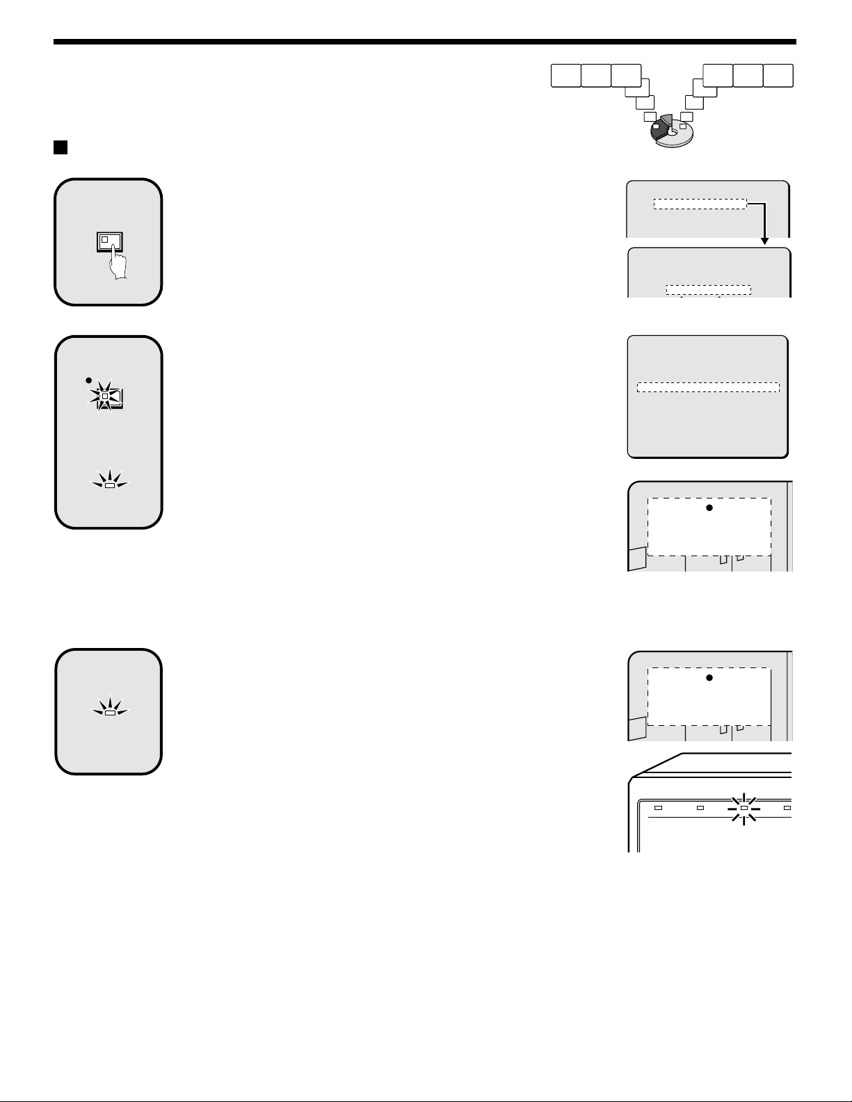
Pre-alarm recording
Setting the time
1
MENU
2
REC/STOP
ALARM
Press the MENU button to display the LANGUAGE/CLOCK SET menu, and set
the date and time. After the setting has been made, press the EXIT/OSD button,
the date and time appear in the operating display. (See page 42.)
Set pre-alarm recording.
Press the MENU button to display the ALARM REC MODE SET menu. Set
ALARM RECORDING to the desired alarm recording setting (example: MODE1).
The *** setting for PRE-ALARM RECORDING will be set to “OFF”, so change it
to “ON”. (See page 56.)
Press the EXIT/OSD button to return to the normal screen. “PRE” appears in the
operating display, the ALARM indicator illuminates and pre-alarm recording
starts (the a mark does not appear).
The same monitored image as in the normal recording area is recorded
repeatedly in the alarm recording area.
Recording onto the hard disk proceeds automatically (default setting) according
to the following settings. The settings can be changed between long-period
recording and high-quality recording in five steps. (See page 49.)
Hard disk recording areas:
•
Normal recording area: 80%
Alarm recording area: 19%
Archive area: 1%
Picture quality: EN (Enhanced)
•
Recording method: Field
•
Recording speed: 0.10 seconds (54H)
•
Pre-alarm images
are recorded
Monitored images
are recorded
<MAIN MENU 1>
1.LANGUAGE/CLOCK SET ->
2.VIDEO INPUT SET ->
3.RECORDING AREA SET ->
4.RECORDING CONDITIONS SET ->
<LANGUAGE/LANGUE/IDIOMA>
ENGLISH
<CLOCK SET>
01-01-2001 MON 00:00:00
<ALARM REC MODE SET>
PICTURE QUALITY : ENHANCED
FRAME/FIELD RECORDING : FIELD
AUDIO RECORDING : OFF
ALARM RECORDING : MODE1
REC CYCLE : 0.10SEC. DURATION: 1SEC
PRE-ALARM RECORDING : ¤¤¤
REC CYCLE : ¤¤¤ SEC. DURATION: ¤¤¤
=> (46400 ALARMS CAN BE RECORDED)
ALARM TRIGGER : ALARM
MOTION SENSOR ->
10-05-01 PRE 0000
18:10:25 EN 0.10SEC
3
ALARM
When an alarm is received, pre-alarm recording stops
automatically and the alarm images are recorded.
The “PRE” disappears from the operating display, “ALARM” flashes and the
ALARM indicator flashes.
Note:
When the remaining area in the alarm recording area reaches 1%, the
•
ALARM FULL indicator on the front panel flashes. If recording is continued
under these conditions, the recording area is filled and the recording stops.
In the RECORDING AREA SET settings, carry out the AREA FULL RESET
operation for the normal recording area.
Recording will then be possible from the beginning again. (See page 48.)
Refer to the recording speed tables for details on the pre-alarm recording
•
speeds. (See page 12.)
10-06-01 ALARM 0000
09:30:15 EN 0.10SEC
POWER FULL
ALARM FULL
LOC
18
English
Page 20
PLAYING BACK IMAGES RECORDED IN THE
NORMAL RECORDING AREA
The digital video recorder can play back recorded images in the normal recording area (normal recording, timer recording).
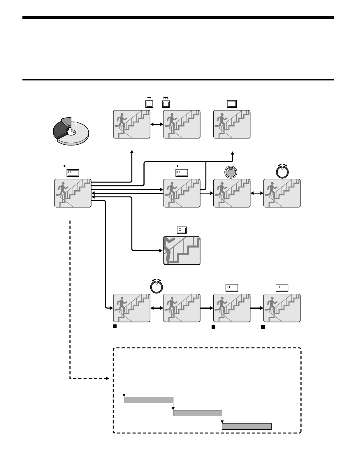
Playback operations
Normal recording area
PLAY/STOP
b Playback
(See page 20.)
ALARM
b Skipping to the previous or next alarm
(See page 25.)
STILL
b Still image
(See page 22.)
ZOOM
SEARCH
FRAME/FIELD
b Switching between frame and field
(See page 23.)
b Frame advance
(forward/reverse)
(See page 22.)
b Slow playback
(See page 20.)
b Zooming images (See page 21.)
SHUTTLE HOLD SHUTTLE HOLD
Fast forward/fast rewind playback
(See page 20.)
Locking speed for
fast forward/rewind
playback
(See page 20.)
Normal playback
• When playing back recordings for the first time:
The recorded images will be played back from the beginning.
• When playing back for the second or subsequent time:
Playback will start from the point where the last playback session ended.
(Starting point for
first playback)
Ending point
(Starting point for
second playback)
Ending point
(Starting point for
third playback)
Releasing speed
lock
Ending point
English
19
Page 21
PLAYING BACK IMAGES RECORDED IN THE NORMAL RECORDING
AREA
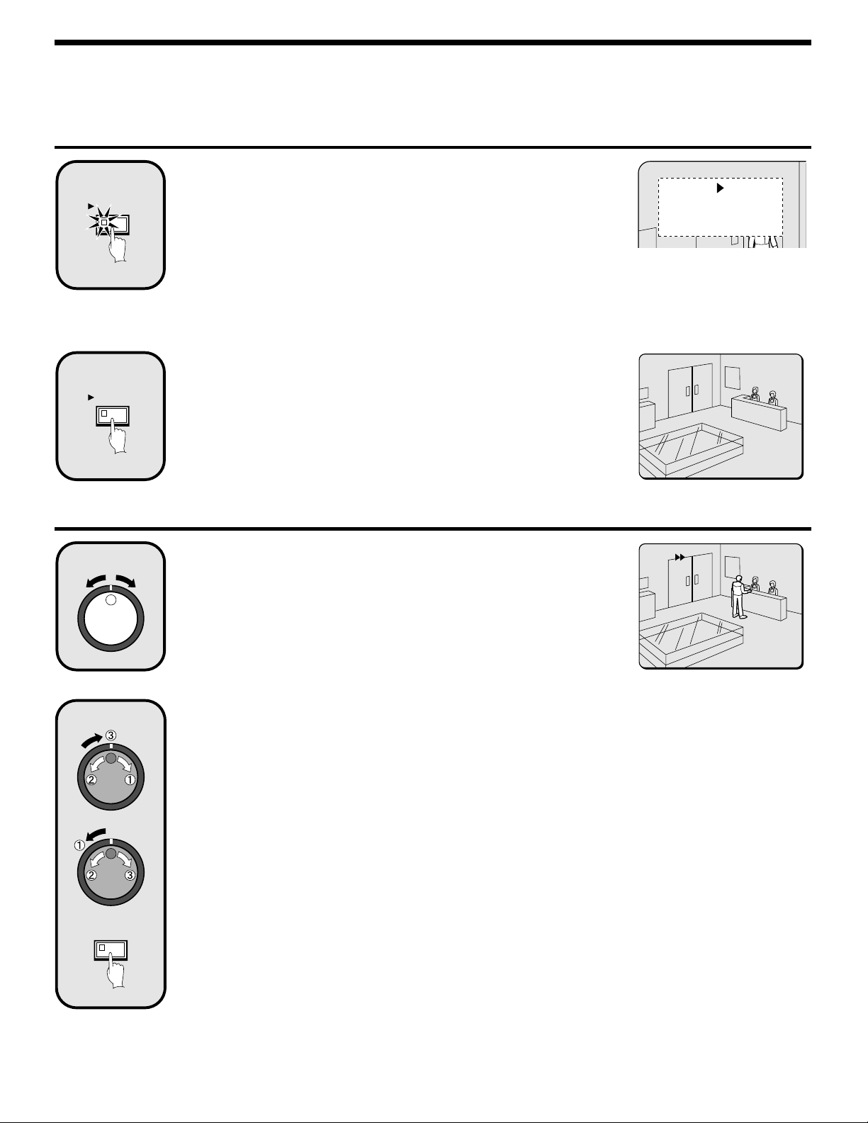
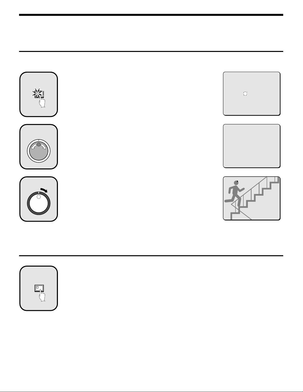
Playback
Press the PLAY/STOP button.
1
PLAY/STOP
2
PLAY/STOP
c appears in the operating display and the images recorded in the normal
recording area are played back.
Note:
Image playback starts from the point (time) that the recording started.
•
If there is no starting position, or if a reset has been made, the oldest
recorded image is played back.
When playback is finished, playback mode is automatically paused.
•
The pause (h) symbol appears in the operating display and the STILL
indicator illuminates.
If playback has been carried out at least once, playback will start from the
•
position where the last playback session ended.
Press the PLAY/STOP button again.
Playback stops.
Note: If playback is started just as recording is being carried out, recording will
have priority, so that the playback images may be paused momentarily.
10-26-01
11:02:50 EN 0.10SEC
11-20-01
04:00:00 EN 0.10SEC
Fast forward/rewind playback
Turn the shuttle dial clockwise (or counterclockwise) during
1
2
SHUTTLE HOLD
playback.
When the shuttle dial is turned clockwise, e appears in the operating display
and fast forward playback starts. If it is turned counterclockwise, f appears in
the operating display and rewind playback starts.
When you release the shuttle dial, normal playback resumes.
Changing the playback speed
(Fast forward/slow playback)
1 Turn the jog dial clockwise.
Fast forward playback starts and e appears in the operating display.
2 Turn the jog dial counterclockwise.
Slow playback starts and hc appears in the operating display.
3 Return to normal playback.
Turn the jog dial clockwise. c appears in the operating display.
(Rewind/slow playback)
1 Turn the shuttle dial counterclockwise (fix at rewind).
d will be displayed, so press the SHUTTLE HOLD button. The SHUTTLE HOLD indicator will illuminate and the
rewind playback speed will be fixed at the current speed.
2 Turn the jog dial counterclockwise.
The speed becomes faster than for normal rewind playback, and f appears in the operating display.
3 Turn the jog dial clockwise.
Slow rewind playback starts and dh appears in the operating display.
4 Return to normal playback.
Turn the jog dial counterclockwise. c appears in the operating display.
11-17-01
02:38:00 EN 0.10SEC
20
English
Page 22
PLAYING BACK IMAGES RECORDED IN THE NORMAL RECORDING
AREA
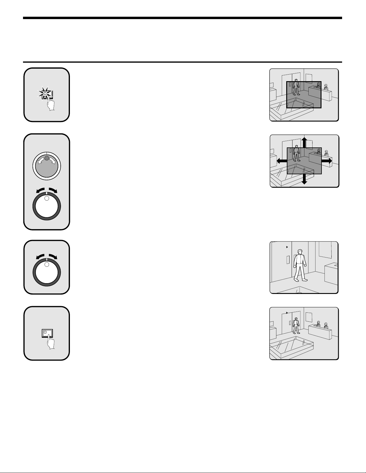
Zooming the image during playback
Press the ZOOM button during playback.
1
ZOOM
2
The zoom frame (blue) appears in the center of the screen.
Move the zoom frame to the position where the image is to
be enlarged.
Turn the jog dial clockwise to move the zoom frame to the right.
•
Turn it counterclockwise to move the zoom frame to the left.
Turn the shuttle dial clockwise to change to vertical movement. Then turn the
•
jog dial clockwise to move the zoom frame upward and turn it
counterclockwise to move the zoom frame downward.
Move the zoom frame to the position to be enlarged.
3
4
ZOOM
Turn the shuttle dial.
The area inside the zoom frame is enlarged (2x).
Press the ZOOM button (to cancel zooming).
The image zooming is canceled and normal playback continues.
Note:
The display cannot be enlarged even while monitoring a camera image.
•
The ZOOM button cannot be selected, when a multiplexer is used as a video
•
input.
The picture quality becomes coarser when the image is zoomed.
•
11-17-01
02:36:00 EN 0.10SEC
11-17-01
02:36:00 EN 0.10SEC
English
21
Page 23
PLAYING BACK IMAGES RECORDED IN THE NORMAL RECORDING
AREA
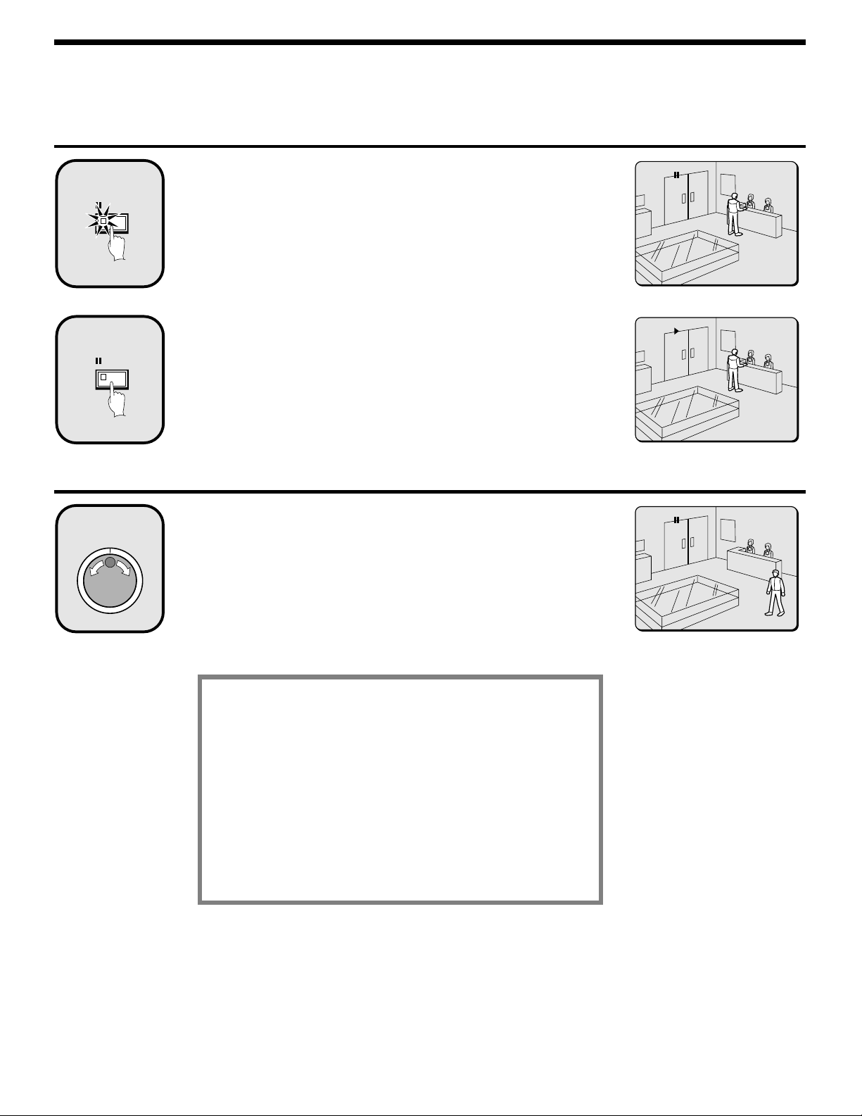
Viewing still images
Press the STILL button during playback.
1
2
h appears in the operating display and a still image is displayed.
STILL
Press the STILL button once more.
Still mode is canceled.
STILL
11-17-01
02:38:00 EN 0.10SEC
11-17-01
02:38:20 EN 0.10SEC
Frame advance (forward/reverse)
Turn the jog dial clockwise (or counterclockwise) in still
1
mode.
Turn the jog dial clockwise to advance the still image by one frame (one field).
Turn it counterclockwise to rewind the still image by one frame (one field).
Note: If the jog dial is turned quickly, the frame feed speed also increases.
During the following operations the picture may appear
distorted or momentarily frozen. This is normal and not a
malfunction.
During the continuous playback from the normal and the
•
alarm recording area, the picture may be distorted when
the recording area is switched.
When playing back during an alarm recording, during
•
continuous playback from the normal and alarm
recording area, during normal playback or when using
the fast forward/rewind playback the picture may appear
momentarily frozen.
17-11-01
02:50:08 EN 0.10SEC
22
English
Page 24
PLAYING BACK IMAGES RECORDED IN THE NORMAL RECORDING
AREA
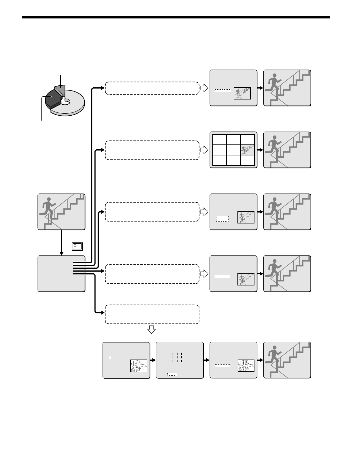
Selecting a camera image channel for playback
When the digital video recorder has been connected to a multiplexer (sold separately) and camera images have been recorded, you can specify the
channel (camera number) for the images recorded and play them back.
Press the CHANNEL button while playback is paused.
1
CHANNEL
The screen for selecting the camera number for cameras connected to the
multiplexer appears.
Use the jog dial to specify the channel (example: camera 4).
PLEASE SELECT CHANNEL
-- CHANNEL
CHANGE WITH JOG. SET WITH SHUTTLE
2
PLEASE SELECT CHANNEL
4 CHANNEL
CHANGE WITH JOG. SET WITH SHUTTLE
Turn the shuttle dial clockwise.
3
“c” appears in the operating display, and playback of images from the specified
channel starts.
Note:
If the digital video recorder is not connected to a multiplexer that allows
•
decoding of channel information (camera numbers), channels can not be
specified for playback.
When this operation is carried out, only the specified channel is played back,
•
and so other channels are not displayed.
When a channel is selected, the multiplexer title information and date
•
information may not be fully displayed in some cases.
Switching between frame and field playback
Press the SEARCH FRAME/FIELD button while frame
1
FRAME/FIELD
SEARCH
recording images are being played back.
The screen changes between frame and field playback each time the button is
pressed.
Note:
Switching between frame and field playback is only possible when images
•
that have been recorded in frame mode are being played back.
When playing back of frame recording images that contain rapid movement,
•
instability may occur in the images.
CH4
10-27-01
13:38:33 SF 0.26SEC
English
23
Page 25
SEARCHING FOR RECORDED IMAGES
Images that have been recorded in the alarm recording area and in the archive area can be played back. Furthermore, images can also be searched
for by recording date and time, and you can also search for moving objects that have been detected by a motion sensor during image playback.
a Alarm search (See page 25.)
Archive area
Alarm image search and playback
<ALARM SEARCH>
NO DATE TIME TOTAL ALARM
0108 12-20 05:37 0234
0107 12-19 14:23
0106 12-16 11:13
0105 12-16 16:13
0104 12-15 10:13
0103 12-13 15:19
0102 12-13 11:15
0101 12-13 11:13
MOVE:JOG SELECT:SHUTTLE
Preview display Single-screen display
Alarm recording area
SEARCH
FRAME/FIELD
<SEARCH>
ALARM SEARCH ->
ALARM THUMBNAIL SEARCH ->
TIME DATE SEARCH ->
ARCHIVE AREA SEARCH ->
MOTION DETECTION SEARCH ->
MOVE:JOG SELECT:SHUTTLE
Alarm image thumbnail search and
playback
Searching and playing back recorded
images by date/time
Playing back images saved (copied) in
the archive area
a Alarm image thumbnail search (See page 26.)
0109 0108 0107
0106 0105 0104
0103 0102 0101
Thumbnail display
Single-screen display
a Time/date search (See page 27.)
<TIME DATE SEARCH>
RECORDING TOP : 12-15-01 08:00
RECORDING END : 12-22-01 17:00
SEARCH :
DATE TIME
12-20-01 05:37
PREVIEW ->
VIEW ->
CHANGE:JOG SET:SHUTTLE
Preview display
Single-screen display
a Archive area search (See page 29.)
<ARCHIVE AREA SEARCH>
NO DATE START CAPACITY
0108 12-20 05:37 TOTAL - 1024MB
0107 12-19 14:23 USED - 400MB
0106 12-16 11:13
0105 12-16 16:13
0104 12-15 10:13
0103 12-13 15:19
0102 12-13 11:15
0101 12-13 11:13
MOVE:JOG SELECT:SHUTTLE
Preview display
Single-screen display
Searching for and playing back moving
objects detected by a motion sensor
a Motion detection search (See page 30.)
<MOTION DETECTION SEARCH>
SEARCH FROM : NORMAL / CHANNEL : 4
START :
10-28-01 08:00
END :
10-28-01 20:00
MOTION SENSOR ->
PREVIEW ->
VIEW ->
MOVE:JOG SELECT:SHUTTLE
Date/time search of an image
----------
----------
---úúú----
---úúú----
---úúú----
----------
----------
----------
LEVEL : 6 EXIT
Motion sensor setting Single-screen display
for motion detection
24
<MOTION DETECTION SEARCH>
SEARCH FROM : NORMAL / CHANNEL : 4
START :
10-28-01 10:00
END :
10-28-01 20:00
MOTION SENSOR ->
PREVIEW ->
VIEW ->
MOVE:JOG SELECT:SHUTTLE
Preview display
English
Page 26
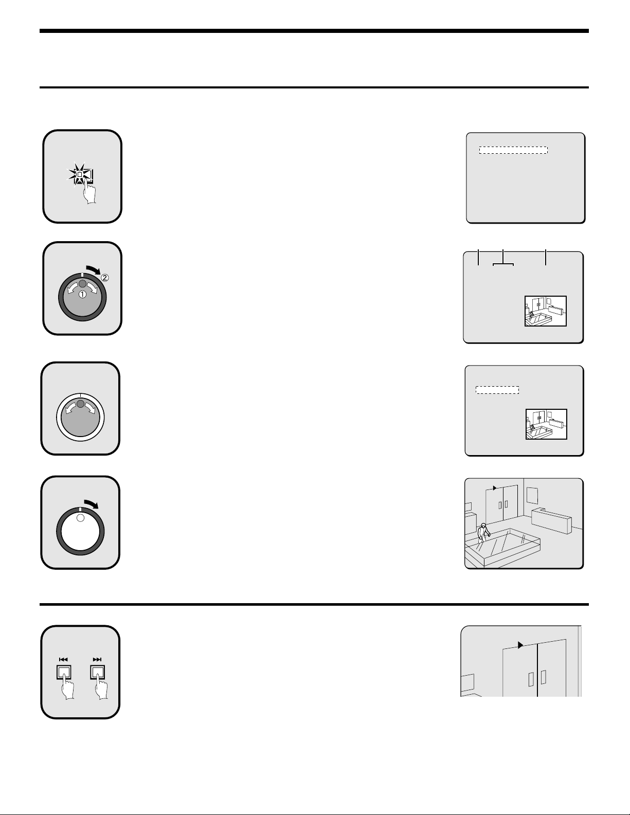
SEARCHING FOR RECORDED IMAGES
Alarm search
All alarm recording images in the alarm recording area can be searched for and played back. If pre-alarm images have is recorded, the images
immediately before the alarms can also be played back.
1
2
3
SEARCH
FRAME/FIELD
Press the SEARCH FRAME/FIELD button during recording
or when the digital video recorder is stopped.
The SEARCH screen appears.
Use the jog dial to select ALARM SEARCH and then turn the
shuttle dial clockwise.
The ALARM SEARCH screen appears.
NO: Alarm number appears.
1
DATE/TIME: The date and time that the alarm was received and the images
2
were recorded appears.
TOTAL ALARM: The total number of alarm images recorded appears.
3
Use the jog dial to move the cursor in order to select the
images to be played back.
The selected alarm image appears in the preview screen.
Note:
Up to eight items of alarm information can be displayed on the ALARM
•
SEARCH screen. When the jog dial is turned, the previous or next alarm
information screen appears.
To end this search mode, press the SEARCH FRAME/FIELD button.
•
<SEARCH>
ALARM SEARCH ->
ALARM THUMBNAIL SEARCH ->
TIME DATE SEARCH ->
ARCHIVE AREA SEARCH ->
MOTION DETECTION SEARCH ->
MOVE:JOG SELECT:SHUTTLE
12 3
<ALARM SEARCH>
NO DATE TIME TOTAL ALARMS
008 12-20 05:37 0010
007 12-19 14:23
006 12-16 11:13
005 12-16 16:13
004 12-15 10:13
003 12-13 15:19
002 12-13 11:15
001 12-13 11:13
MOVE:JOG SELECT:SHUTTLE
<ALARM SEARCH>
NO DATE TIME TOTAL ALARM
008 12-20 05:37 0234
007 12-19 14:23
006 12-16 11:13
005 12-16 16:13
004 12-15 10:13
003 12-13 15:19
002 12-13 11:15
001 12-13 11:13
MOVE:JOG SELECT:SHUTTLE
4
Alarm search 2
1
ALARM
Turn the shuttle dial clockwise.
The preview image appears in a single-screen display and playback starts.
Note:
You can also use the shuttle dial or jog dial to carry out operations such as
•
pausing and fast-forward playback.
Alarm search starts playback from the image that was recorded at the instant
•
the alarm occurred, so if you are viewing pre-alarm images, use the shuttle
operations to carry out rewind playback.
Press an ALARM skip button during playback.
If you press the û button, playback skips to the previous alarm image.
•
If you press the ù button, playback skips to the next alarm image.
•
Note: When playing back using alarm search, the playback will pause at the
start and at the end of each alarm recording. Use the ALARM skip buttons
to play back previous and subsequent alarm recordings.
11-18-01 ALARM 0004
25:03:12 EN 0.10SEC
11-18-01 ALARM 0004
25:03:12 EN 0.10SEC
English
25
Page 27
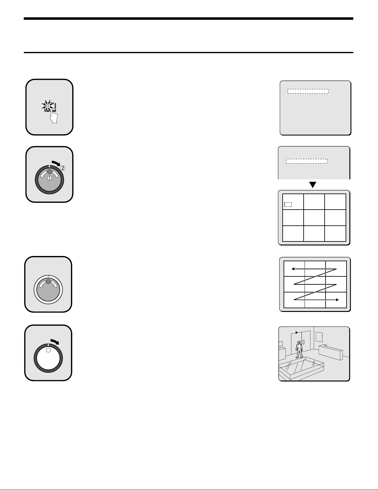
SEARCHING FOR RECORDED IMAGES
Alarm thumbnail search
Alarm images can be searched for and played back from thumbnails.
All alarm images recorded in the alarm recording area are displayed as thumbnails.
1
2
3
SEARCH
FRAME/FIELD
Press the SEARCH FRAME/FIELD button during recording
or when the digital video recorder is stopped.
The SEARCH screen appears.
Use the jog dial to select ALARM THUMBNAIL SEARCH and
then turn the shuttle dial clockwise.
The last nine alarm recording images recorded appear.
The alarm number appears with each alarm recording image, and the alarm
number of the currently-selected alarm image flashes.
Use the jog dial to move the cursor in order to select the
images to be played back.
The alarm number of the currently-selected alarm image flashes.
Note:
Up to nine items of alarm information including thumbnails can be displayed.
•
When the jog dial is turned, the previous or next alarm information screen
appears.
To end this search mode, press the SEARCH FRAME/FIELD button.
•
<SEARCH>
ALARM SEARCH ->
ALARM THUMBNAIL SEARCH ->
TIME DATE SEARCH ->
ARCHIVE AREA SEARCH ->
MOTION DETECTION SEARCH ->
MOVE:JOG SELECT:SHUTTLE
<SEARCH>
ALARM SEARCH ->
ALARM THUMBNAIL SEARCH ->
TIME DATE SEARCH ->
ARCHIVE AREA SEARCH ->
MOTION DETECTION SEARCH ->
MOVE:JOG SELECT:SHUTTLE SEARCH:EXIT
0109 0108 0107
0106 0105 0104
0103 0102 0101
0109 0108 0107
0106 0105 0104
0103 0102 0101
4
Turn the shuttle dial clockwise.
The selected image appears in a single-screen display and playback starts.
Note:
You can also use the shuttle dial or jog dial to carry out operations such as
•
pausing and fast-forward playback.
Only the contents of each alarm can be played back, in the same way as for
•
alarm searching. Use the ALARM skip buttons to play back previous and
subsequent alarm recordings.
26
11-18-01 ALARM 0003
25:02:00 EN 0.10SEC
English
Page 28
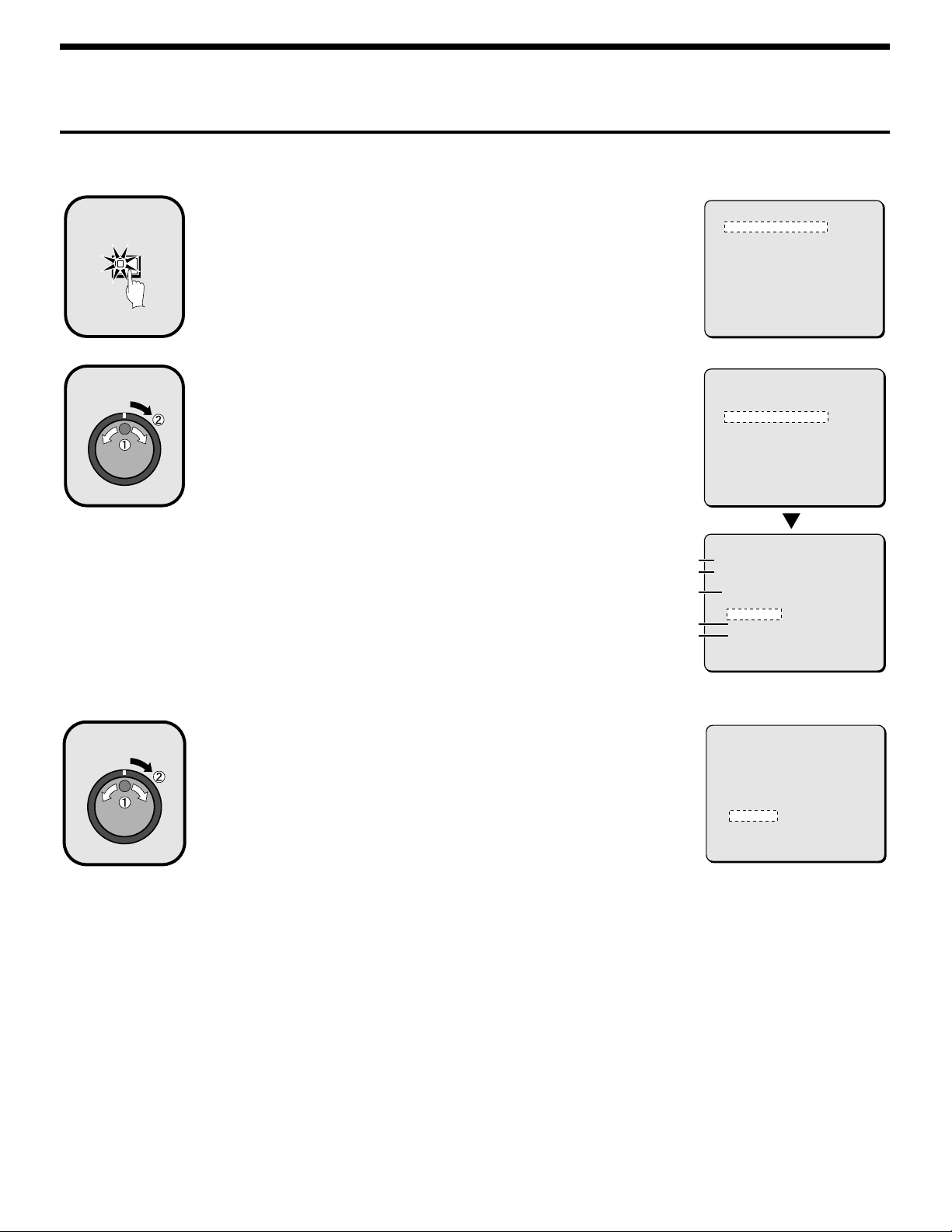
SEARCHING FOR RECORDED IMAGES
Time/date search
The recording date and time for images in the normal recording area (normal recording and timer recording images) and in the alarm recording area of
the hard disk can be specified and the images can be played back.
1
FRAME/FIELD
2
SEARCH
Press the SEARCH FRAME/FIELD button during recording
or when the digital video recorder is stopped.
The SEARCH screen appears.
Use the jog dial to select TIME DATE SEARCH and then turn
the shuttle dial clockwise.
The TIME DATE SEARCH screen appears.
RECORDING TOP: The date and time of the first recorded image is
1
RECORDING END: The date and time of the latest (most recently) recorded
2
SEARCH: Enter the date and time to be displayed in this area.
3
PREVIEW: A preview image appears.
4
VIEW: The selected image appears on the monitor as a single-screen image.
5
displayed.
image is displayed.
<SEARCH>
ALARM SEARCH ->
ALARM THUMBNAIL SEARCH ->
TIME DATE SEARCH ->
ARCHIVE AREA SEARCH ->
MOTION DETECTION SEARCH ->
MOVE:JOG SELECT:SHUTTLE
<SEARCH>
ALARM SEARCH ->
ALARM THUMBNAIL SEARCH ->
TIME DATE SEARCH ->
ARCHIVE AREA SEARCH ->
MOTION DETECTION SEARCH ->
MOVE:JOG SELECT:SHUTTLE
<TIME DATE SEARCH>
RECORDING TOP : 10-25-01 08:00
1
RECORDING END : 10-28-01 17:00
2
SEARCH :
3
DATE TIME
10-25-01 08:00
PREVIEW ->
4
VIEW ->
5
CHANGE:JOG SET:SHUTTLE
3
Example: To search for 8 pm on 26 October 2001
1
Turn the jog dial clockwise and select “10”.
2
Turn the shuttle dial clockwise, and then use the jog dial to change “25” to
“26”.
3 Turn the shuttle dial clockwise and select “01”.
4 Turn the shuttle dial clockwise, and then use the jog dial to change “08” to
“20”.
5 Turn the shuttle dial clockwise and select “00”. Then turn the shuttle dial.
The cursor moves to PREVIEW.
<TIME DATE SEARCH>
RECORDING TOP : 10-25-01 08:00
RECORDING END : 10-28-01 17:00
SEARCH :
DATE TIME
10-26-01 20:00
PREVIEW ->
VIEW ->
CHANGE:JOG SET:SHUTTLE
English
27
Page 29
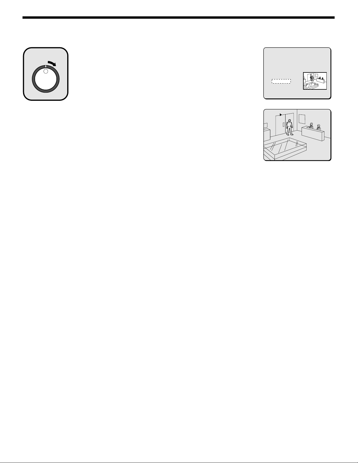
SEARCHING FOR RECORDED IMAGES
4
Turn the shuttle dial clockwise
A search display appears while searching is in progress, and then a preview
screen showing the date and time entered appears.
Note: If there are no images that match the time exactly, the image closest to
the selected time range is displayed.
Use the jog dial to select VIEW, and then turn the shuttle
5
dial clockwise.
The preview image is displayed and played back in a single-screen.
Note:
A single-screen image can be displayed when date and time are entered and
•
VIEW is selected, even without displaying a preview.
You can also use the shuttle dial or jog dial to carry out operations such as
•
pausing and fast-forward playback.
<TIME DATE SEARCH>
RECORDING TOP : 11-05-00 08:00
RECORDING END : 12-22-00 17:00
SEARCH :
DATE TIME
11-17-01 02:36:10
PREVIEW ->
VIEW ->
CHANGE:JOG SET:SHUTTLE
11-17-01
02:36:10 EN 0.10SEC
28
English
Page 30
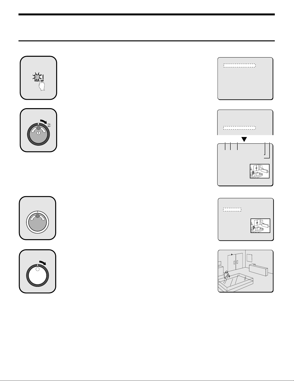
SEARCHING FOR RECORDED IMAGES
Archive area search
You can play back images that have been saved (copied) in the archive area.
1
FRAME/FIELD
2
SEARCH
Press the SEARCH FRAME/FIELD button during recording
or when the digital video recorder is stopped.
The SEARCH screen appears.
Use the jog dial to select ARCHIVE AREA SEARCH and then
turn the shuttle dial clockwise.
The ARCHIVE AREA SEARCH screen appears.
NO: The archive number is displayed.
1
DATE: The date of the recorded image is displayed.
2
START: The start time of the recorded image is displayed.
3
TOTAL: The total capacity of the archive area is displayed.
4
USED: The recorded part of the archive area is displayed.
5
<SEARCH>
ALARM SEARCH ->
ALARM THUMBNAIL SEARCH ->
TIME DATE SEARCH ->
ARCHIVE AREA SEARCH ->
MOTION DETECTION SEARCH ->
MOVE:JOG SELECT:SHUTTLE
<SEARCH>
ALARM SEARCH ->
ALARM THUMBNAIL SEARCH ->
TIME DATE SEARCH ->
ARCHIVE AREA SEARCH ->
MOTION DETECTION SEARCH ->
12 3 45
MOVE:JOG SELECT:SHUTTLE SEARCH:EXIT
<ARCHIVE AREA SEARCH>
NO DATE START CAPACITY
0108 12-20 05:37 TOTAL - 1024MB
0107 12-19 14:23 USED - 400MB
0106 12-16 11:13
0105 12-16 16:13
0104 12-15 10:13
0103 12-13 15:19
0102 12-13 11:15
0101 12-13 11:13
MOVE:JOG SELECT:SHUTTLE
3
4
Use the jog dial to move the cursor in order to select the
images to be played back.
The selected alarm image appears in the preview screen.
Note:
Up to eight items of information can be displayed in the ARCHIVE AREA
•
SEARCH screen.
When the jog dial is turned, the previous or next archive screen appears.
To end this search mode, press the SEARCH FRAME/FIELD button.
•
Turn the shuttle dial clockwise.
The selected image appears in a single-screen display and playback starts.
Note:
A single-screen image can be displayed when the cursor is moved to the
•
image to be played back and the shuttle dial is turned clockwise, even without
displaying a preview.
You can also use the shuttle dial or jog dial to carry out operations such as
•
pausing and fast-forward playback.
<ARCHIVE AREA SEARCH>
NO DATE START CAPACITY
0108 12-20 05:37 TOTAL - 1024MB
0107 12-19 14:23 USED - 400MB
0106 12-16 11:13
0105 12-16 16:13
0104 12-15 10:13
0103 12-13 15:19
0102 12-13 11:15
0101 12-13 11:13
MOVE:JOG SELECT:SHUTTLE
11-18-01 ALARM 0004
25:03:12 EN 0.10SEC
English
29
Page 31

SEARCHING FOR RECORDED IMAGES
Motion detection search
When a motion sensor is set for images recorded in the normal recording area (normal recording and timer recording images) or for images recorded
in the alarm recording area of the hard disk, you can search for images that have changed because of the entry of a suspicious person, for instance,
and play back only those images.
Note:
If carrying out motion detection searches of multiplexer images, change the setting for MULTIPLEXER in the VIDEO INPUT SET menu to
•
something other than “NO USE”.
If the digital video recorder is connected to a Sanyo multiplexer that allows decoding of channel information (camera numbers), channels can be
•
specified so that only images from those channels are searched for. If any other type of multiplexer is connected, this setting is not possible.
1
FRAME/FIELD
2
3
SEARCH
Press the SEARCH FRAME/FIELD button during recording
or when the digital video recorder is stopped.
The SEARCH screen appears.
Use the jog dial to select MOTION DETECTION SEARCH and
then turn the shuttle dial clockwise.
The MOTION DETECTION SEARCH screen appears.
Use the jog dial to select SEARCH FROM and then turn the
shuttle dial clockwise.
The ALARM display flashes.
<SEARCH>
ALARM SEARCH ->
ALARM THUMBNAIL SEARCH ->
TIME DATE SEARCH ->
ARCHIVE AREA SEARCH ->
MOTION DETECTION SEARCH ->
MOVE:JOG SELECT:SHUTTLE
<SEARCH>
ALARM SEARCH ->
ALARM THUMBNAIL SEARCH ->
TIME DATE SEARCH ->
ARCHIVE AREA SEARCH ->
MOTION DETECTION SEARCH ->
<MOTION DETECTION SEARCH>
SEARCH FROM : ALARM
START : -------- --:- END : -------- --:--
CHANNEL : --
START PREVIEW ->
MOVE:JOG SELECT:SHUTTLE
4
5
Use the jog dial to select the recording area (example:
NORMAL), and then turn the shuttle dial clockwise.
The cursor moves to CHANNEL.
Note: If the setting for MULTIPLEXER in the VIDEO INPUT SET menu is set to
“NO USE”, the cursor will move to START PREVIEW.
Examples of recording area selection:
ALARM: Only images in the alarm recording area are searched.
•
NORMAL: Only images in the normal recording area are searched.
•
ALARM & NORMAL: Images in both the alarm recording area and the
•
normal recording area are searched.
Turn the shuttle dial clockwise, use the jog dial to select the
camera number (example: 4), and then turn the shuttle dial
clockwise.
The cursor moves to START PREVIEW.
30
<MOTION DETECTION SEARCH>
SEARCH FROM : NORMAL
START : 10-28-01 08:00
END : 10-28-01 20:00
CHANNEL : --
START PREVIEW ->
MOVE:JOG SELECT:SHUTTLE
<MOTION DETECTION SEARCH>
SEARCH FROM : NORMAL
START : 10-28-01 08:00
END : 10-28-01 20:00
CHANNEL : 4
START PREVIEW ->
MOVE:JOG SELECT:SHUTTLE
English
Page 32

SEARCHING FOR RECORDED IMAGES
6
7
Turn the shuttle dial clockwise.
The screen changes and the preview screen for camera number 4 appears.
START: The date and time for the first image in the selected recording area
1
appears.
You can also select the screen which has a motion sensor set.
END: The date and time for the last image in the selected recording area
2
appears.
One hour is added to the time that is displayed.
You can also select the screen which has a motion sensor set.
MOTION SENSOR: The motion sensor appears.
3
PREVIEW: The selected start point appears.
4
If you turn the shuttle dial clockwise, you can check the images
up until the end point.
VIEW: The selected image appears on the monitor as a single-screen image
5
in a normal screen.
Turn the shuttle dial clockwise.
Use the jog dial to set the START date and time (example: 10.00 am on the
current day) for the motion sensor setting, and then turn the shuttle dial
clockwise.
The image for the specified time appears in the preview screen, and the cursor
moves to the END date and time setting location.
<MOTION DETECTION SEARCH>
SEARCH FROM : NORMAL
START : 10-28-01 08:00
END : 10-28-01 20:00
CHANNEL : 4
START PREVIEW -> SEARCHING
MOVE:JOG SELECT:SHUTTLE
<MOTION DETECTION SEARCH>
SEARCH FROM : NORMAL / CHANNEL : 4
START :
10-28-01 08:00
1
END :
10-28-01 10:00
2
MOTION SENSOR ->
3
PREVIEW ->
4
VIEW ->
5
MOVE:JOG SELECT:SHUTTLE
<MOTION DETECTION SEARCH>
SEARCH FROM : NORMAL / CHANNEL : 4
START :
10-28-01 08:00
END :
10-28-01 20:00
MOTION SENSOR ->
PREVIEW ->
VIEW ->
MOVE:JOG SELECT:SHUTTLE
8
9
Turn the shuttle dial clockwise.
Use the jog dial to set the END date and time (example: 8.00 pm on the current
day) for the motion sensor setting, and then turn the shuttle dial clockwise.
The cursor moves to MOTION SENSOR.
Turn the shuttle dial clockwise.
The motion sensor setting screen appears.
Set the motion sensor to cover the area where you would like movement to be
observed.
Move the cursor to EXIT and turn the shuttle dial clockwise. The display returns
to the MOTION DETECTION SEARCH screen. Refer to page 58 for details on
motion sensor settings.
<MOTION DETECTION SEARCH>
SEARCH FROM : NORMAL / CHANNEL : 4
START :
10-28-01 10:00
END :
10-28-01 20:00
MOTION SENSOR ->
PREVIEW ->
VIEW ->
MOVE:JOG SELECT:SHUTTLE
<MOTION DETECTION SEARCH>
SEARCH FROM : NORMAL / CHANNEL : 4
START :
10-28-01 10:00
END :
10-28-01 20:00
MOTION SENSOR ->
PREVIEW ->
VIEW ->
MOVE:JOG SELECT:SHUTTLE
----------
----------
---úúú----
---úúú----
---úúú----
----------
----------
----------
LEVEL : 6 EXIT
English
31
Page 33

SEARCHING FOR RECORDED IMAGES
10
11
1
1
2
2
Use the jog dial to move the cursor to PREVIEW, and then
turn the shuttle dial clockwise. The screen showing the
motion sensor settings appear in the preview screen each
time the shuttle dial is turned.
Note: If no motion sensor settings have been made, “NOT FOUND” appears, so
make sure that the motion sensor settings have been made correctly.
To view a motion sensor setting in a single-screen display,
use the jog dial to move the cursor to VIEW and then turn
the shuttle dial clockwise.
The display changes from the specified image to normal playback.
Note: When using a multiplexer and the camera number has been specified as a
channel when carrying out motion detector searches, only images for the
specified camera number will be played back. For playback of all cameras
the playback has first to be switched off and then switched on again.
Furthermore, the multiplexer title information and date information may not
be fully displayed at this time in some cases.
<MOTION DETECTION SEARCH>
SEARCH FROM : NORMAL / CHANNEL : 4
START :
10-28-01 10:00
END :
10-28-01 20:00
MOTION SENSOR ->
PREVIEW ->
VIEW ->
MOVE:JOG SELECT:SHUTTLE
32
English
Page 34

SAVING (COPYING) RECORDED IMAGES
Normal
recording area
Alarm
recording
area
Normal
recording area
Alarm
recording
area
Normal
recording area
Alarm
recording
area
Normal
recording area
Alarm
recording
area
Normal
recording area
Alarm
recording
area
Normal
recording area
Alarm
recording
Important images that have been recorded onto the normal recording area or alarm recording area can be copied to a CompactFlash card or to the
archive area of the hard disk.
A Copying images to the hard disk archive area
Copying Copying
Archive area
Alarm
Alarm
recording
recording
area
area
Normal
Normal
recording area
recording area
Hard disk
B Copying images from archive area to a CompactFlash card
Automatic copying Automatic copying
Archive area
Alarm
Alarm
recording
recording
area
area
Normal
Normal
recording area
recording area
Hard disk
C Copying images from the archive area to a DDS (DAT) drive or CD-R drive
Copying Copying
Alarm
Alarm
recording
recording
area
area
Hard disk
Archive area
Normal
Normal
recording area
recording area
CompactFlashCard
CF card or microdrive
EJECT
SCSI
Microdrive
S-VIDEO
Note:
Copied images are stored as a single picture.
•
If you are downloading images to a CompactFlash card, the images are automatically saved in the archive area, and they are then copied from the
•
archive area to the CompactFlash card. The images will no longer remain in the archive area.
If the archive area has become full, use the AREA FULL RESET setting for the archive area in the RECORDING AREA SET menu to delete
•
unneeded images.
English
33
DDS (DAT) drive or
CD-R drive
(sold separately)
Page 35

SAVING (COPYING) RECORDED IMAGES
A Copying images to the hard disk archive
area
Play back the images in the normal recording area or alarm
1
recording area that is to be copied, and pause playback at the
image that is to be copied. (See page 22.)
PLAY/STOP
Example: To copy 10 seconds of images starting from a selected
2
image
While the image to be copied is displayed as a still image,
press the COPY button.
The copy screen appears.
COPY
STILL
COPY TO : ARCHIVE AREA
HOW MANY : 1 PICTURES
START ->
FORMAT COMPACT FLASH ->
CHANGE WITH JOG. SET WITH SHUTTLE
Use the jog dial to select the SECONDS setting, and then
6
turn the shuttle dial clockwise.
PICTURES: Specify the number of images to be copied.
•
SECONDES: Specify the number of seconds of images to be
•
MINUTES: Specify the number of minutes of images to be
•
The cursor moves to START.
Turn the shuttle dial clockwise.
7
Copying of images to the archive area starts. When copying is
complete, “COPY FINISHED” appears.
Note: If you press the COPY button while copying is in progress,
copying is canceled.
copied.
copied (up to 60 minutes).
COPY TO : ARCHIVE AREA
HOW MANY : 10 PICTURES
START ->
COPY TO : ARCHIVE AREA
HOW MANY : 10 PICTURES
START ->
Use the jog dial to select COPY TO and then turn the shuttle
3
dial clockwise.
The ARCHIVE AREA display flashes.
COPY TO : ARCHIVE AREA
HOW MANY : 1 PICTURES
START ->
FORMAT COMPACT FLASH ->
CHANGE WITH JOG. SET WITH SHUTTLE
Use the jog dial to select ARCHIVE AREA and then turn the
4
shuttle dial clockwise.
The cursor moves to HOW MANY.
COPY TO : ARCHIVE AREA
HOW MANY : 1 PICTURES
START ->
Turn the shuttle dial clockwise, use the jog dial to change
5
the setting to “10”, and then turn the shuttle dial clockwise.
The cursor moves to PICTURES.
34
English
Page 36

SAVING (COPYING) RECORDED IMAGES
B Copying images from archive area to a
CompactFlash card
Insert a CompactFlash card into the CompactFlash slot on the
front panel.
When inserting the CompactFlash card, make sure that the direction of
insertion is correct.
A microdrive can also be used for copying images.
(Inserting)
1
2
3
(Removing)
3
Use the jog dial to select COMPACIT FLASH and then turn
3
the shuttle dial clockwise.
The cursor moves to HOW MANY.
COPY TO : COMPACT FLASH
HOW MANY : 1 PICTURES
Turn the shuttle dial clockwise, use the jog dial to change
4
the setting to “ 10” , and then turn the shuttle dial clockwise.
The cursor moves to PICTURES.
COPY TO : COMPACT FLASH
HOW MANY : 10 PICTURES
Use the jog dial to select the SECONDS setting, and then
5
turn the shuttle dial clockwise.
PICTURES: Specify the number of images to be copied.
•
SECONDES: Specify the number of seconds of images to be
•
MINUTES: Specify the number of minutes of images to be
•
copied.
copied (up to 60 minutes).
2
1
Display an image from the archive area as a still image, and
1
then press the COPY button.
The copying screen appears.
Refer to page 29 for details on playing back images from the
archive area.
COPY
COPY TO : ARCHIVE AREA
HOW MANY : 1 PICTURES
START ->
FORMAT COMPACT FLASH ->
CHANGE WITH JOG. SET WITH SHUTTLE
Use the jog dial to select COPY TO and then turn the shuttle
2
dial clockwise.
The ARCHIVE AREA display flashes.
COPY TO : ARCHIVE AREA
HOW MANY : 1 PICTURES
START ->
FORMAT COMPACT FLASH ->
CHANGE WITH JOG. SET WITH SHUTTLE
COPY TO : COMPACT FLASH
HOW MANY : 10 SECONDS
Note:
The limit to the number of images that can be copied is 40000.
•
Copying ends when 40000 images have been copied.
When copying alarm recordings, they can only be copied one at a
•
time.
Turn the shuttle dial clockwise.
6
The COPY indicator illuminates, the COPY TO : COMPACT
FLASH screen appears and copying of images to the
CompactFlash card starts.
When copying is complete, “COPYING COMPLETE” appears.
COPY TO : COMPACT FLASH
HOW MANY : 10 SECONDS
START ->
Note:
If copying images directly from the normal recording area or alarm
•
recording area to a CompactFlash card, the same images will also
be copied to the archive area. However, the images are deleted
after they have been copied.
If you press the COPY button while copying is in progress, copying
•
is canceled.
English
35
Page 37

SAVING (COPYING) RECORDED IMAGES
Formatting CompactFlash cards
You can format CompactFlash cards and microdrives by selecting
“FORMAT COMPACTFLASH”.
You can only use a CompactFlash card that has been formatted to
FAT16 specifications. FAT32 formatted cards cannot be recognized.
COPY TO : ARCHIVE AREA
HOW MANY : 20 PICTURES
START ->
FORMAT COMPACT FLASH ->
CHANGE WITH JOG. SET WITH SHUTTLE
CompactFlash recording area
COMPACT FLASH
SANYO 02032101 IMG00001
12
3
IMG00002
3
IMG00003
3
INDEX.HTM
4
A SANYO folder is created in the root directory.
1
Sub-folders for holding the copied images are created in
2
sequence in the SANYO folder.
Sub-folders are created within the date/time folder with names
3
starting from IMG00001. Each sub-folder can hold 200 images.
To view the file listing using a computer, use a browser such
4
as Internet Explorer 5.0 or later to open the INDEX.HTM files.
The JPEG files can be played back as a slideshow.
Note:
JPG images are recorded as field images, so that when they are
•
viewed using the normal image viewer, they are compressed by
1/2 in the vertical direction. Make sure that you view them using the
INDEX.HTM file.
When frame recording images are copied to a CompactFlash card,
•
the images are copied separately as two field images, so that
frame playback is not possible when viewing these images using a
computer.
Images that have been copied onto a CompactFlash card contain
•
codes for detecting file tampering, and these codes can be
recognized by computer software applications that can detect file
tampering. Contact the place of purchase for details.
00000001.JPG
00000002.JPG
00000003.JPG
IMPORTANT INFORMATION
When the Digital Video Recorder is connected to a multiplexer
(including multiplexers from other manufacturers such as Robot,
DM and Sony), you can copy images from a specified camera
that have been recorded by the Digital Video Recorder to the
archive area or to a CompactFlash card.
1) Multiplexer operation
2) Digital Video Recorder operation
3) Multiplexer operation
4) Digital Video Recorder operation
Note:
If you copy images to the archive recording area of a Digital
Video Recorder or to a CompactFlash card without specifying
the camera channel with the Digital Video Recorder in step 2
above, all camera images from the multiplexer will be copied.
The copying function in this special screen can only be carried
out by multiplexers for which the Digital Video Recorder can
directly decode the multiplexer’s ID information. The multiplexer
interchangeability list is given below.
A. Multiplexers that can be directly decoded
B. Multiplexers that only allow decoding by the multiplexer
Copying camera images to the archive recording
area or to a CompactFlash card
Press the VCR button and display the split screen.
Specify the camera channel to be copied by means of the
procedure in “Selecting a camera image channel for
playback” on page 23.
Press the camera select button for the selected camera to
display the images for that camera in a single screen.
•
If copying images to the archive recording area
Carry out the procedure in “Copying images to the
hard disk area” on page 34.
•
If copying images from the archive recording area to a
CompactFlash card
Carry out the procedure in “Copying images from the
archive area to a CompactFlash card” on page 35.
“COPYING” will be displayed on each screen, and
copying will then start. When copying is complete,
“COPY FINISHED” will be displayed.
Sanyo, Robot, DM, Sony
Pelco, Kalatel, ATV, Ultrak
36
English
Page 38

SAVING (COPYING) RECORDED IMAGES
1
2
3
C Copying images from the archive area
to a DDS (DAT) drive or CD-R drive
☞ Connecting to a drive
Insert a recommended SCSI card for connecting the DDS (DAT)
drive into the PC card slot at the rear of the digital video recorder.
Images from the archive area can be copied to the DDS (DAT) drive,
and images recorded on the DDS (DAT) drive can also be copied to
the archive area.
Recommended SCSI card
••••
Manufacturer: ADAPTEC
Model No.: Slim SCSI 1460
Recommended DDS-3 type DDS (DAT) drive
••••
Manufacturer: Hewlett Packard
Model No.: Super Store dat 24e
Recommended CD-R drive
••••
Manufacturer: YAMAHA
Model: CRW2200SX-VK
To DIGITAL IN/OUT terminal of multiplexer
DIGITAL IN DIGITAL OUT
Backing up
All of the data in the archive area can be backed up on a DDS (DAT)
drive.
Press the COPY button during recording or when the digital
1
video recorder is stopped.
The ARCHIVE SET screen appears.
COPY
Use the jog dial to select BACK UP and then turn the shuttle
2
dial clockwise.
“ARCHIVING TO DDS(DAT) !” appears, and copying then starts.
If you press the COPY button while copying is in progress,
••••
copying is canceled.
When copying is completed, “ ARCHIVE FINISHED!”
••••
appears. Press any button to return to the normal screen.
<ARCHIVE SET>
BACK UP ->
RESTORE ->
ERASE ->
01-01-01
00:00:00 EN 0.10SEC
ARCHIVING TO DDS(DAT) !
DDS (DAT) drive or
CD-R drive
(sold separately)
Note:
When data is converted for storage on a DDS (DAT) drive, the
••••
conversion process may result in an increase in the size of the
Inserting an SCSI card (sold separately)
(Installed)
1
3
2
You can slide the knob to lock
the card.
Note:
The PC card slot is for 16-bit 5 V cards only.
••••
Do not use 32-bit card bus types of card, as they may damage the
PC card slot of the digital video recorder.
Check that the direction of insertion is correct when inserting the
••••
SCSI card.
If an SCSI card or DDS (DAT) drive other than the ones
••••
recommended is used, correct operation cannot be guaranteed.
The compatible CD-R drive is a YAMAHA SCSI CD-R/RW drive, and
••••
the media must be CD-R discs only. CD-RW discs cannot be used.
* DDS (Digital Data Strage)/DAT (Digital Audio Tape).
English
(Removed)
3
2
1
Return the knob after
unlocking.
37
data. If copying images onto a 12 GB tape, it may only be possible
to copy about 10 GB of data.
It will take approximately 4 hours to copy 10 GB of data onto a
••••
DDS (DAT) drive.
<PRESS COPY TO ABORT>
Page 39

SAVING (COPYING) RECORDED IMAGES
Reading data from a DDS (DAT) drive into the
archive area
Note: All of the previously recorded images in the archive area are
deleted when images are transferred in this way.
Press the COPY button during recording or when the digital
1
video recorder is stopped.
The ARCHIVE SET screen appears.
COPY
Use the jog dial to select RESTORE and then turn the shuttle
2
dial clockwise.
The message “LISTING DATA !” appears. When playback is
complete, the RESTORE FROM DDS (DAT) screen appears.
Use the jog dial to select the data to be read into the archive
3
area, and then turn the shuttle dial clockwise.
Reading of data starts. The RESTORE FROM DDS (DAT) screen
appears.
The image data on the DDS (DAT) drive is then saved into the
archive area.
When all data has been read into the archive area, “RESTORE
FINISHED!” appears.
When you play back the images in the archive area, the image
data that has been read can be played back.
<ARCHIVE SET>
BACK UP ->
RESTORE ->
ERASE ->
01-01-01
08:00:00 EN 0.10SEC
LISTING DATA !
<PRESS COPY TO ABORT>
Deleting DDS (DAT) drive image data
Press the COPY button during recording or when the digital
1
video recorder is stopped.
The ARCHIVE SET screen appears.
COPY
Use the jog dial to select ERASE and then turn the shuttle
2
dial clockwise.
The WARNING screen appears.
Use the jog dial to change “ NO” to “ YES”, and then turn the
3
shuttle dial clockwise.
“ERASING MEDIUM!” appears, and when erasing of data from
the tape has been completed, “ERASING FINISHED!” appears.
<ARCHIVE SET>
BACK UP ->
RESTORE ->
ERASE ->
<WARNING>
STORED DATA ON DDS(DAT) WILL BE ERASED !
ARE YOU SURE ?
NO
CHANGE WITH JOG, SET WITH SHUTTLE
01-01-01
08:00:00 EN 0.10SEC
ERASING MEDIUM !
<RESTORE FROM DDS(DAT)>
NO DATE TIME SIZE
0001 12-13-2001 11:13 3.0GB
0002 12-15-2001 10:15 2.0GB
0003 12-17-2001 10:15 2.0GB
STORED DATA ON HDD WILL BE ERASED !
01-01-01
08:00:00 EN 0.10SEC
RESTORING FROM DDS(DAT) !
<PRESS COPY TO ABORT>
38
English
Page 40

SAVING (COPYING) RECORDED IMAGES
Copying images to a CD-R drive
While viewing the still image to be copied from the archive
1
area, press the COPY button.
The COPY screen appears.
Refer to page 29 for details on playing back images in the archive
area.
COPY
COPY TO : ARCHIVE AREA
HOW MANY : 20 PICTURES
START ->
FORMAT COMPACT FLASH ->
CHANGE WITH JOG. SET WITH SHUTTLE
Use the jog dial to select “ COPY TO” , and then turn the shuttle
2
dial clockwise.
The “ARCHIVE AREA” display flashes.
COPY TO : ARCHIVE AREA
HOW MANY : 20 PICTURES
START ->
FORMAT COMPACT FLASH ->
CHANGE WITH JOG. SET WITH SHUTTLE
Use the jog dial to select “ SECONDS” , and then turn the
5
shuttle dial clockwise.
The cursor moves to “START”.
•
PICTURES: The specified number of images are copied
starting from the current image.
•
SECONDS: The specified number of seconds of images are
copied, starting from the current image.
•
MINUTES: The specified number of minutes of images are
coped, starting from the current image.
•
EVENTS: The specified number of events are copied, starting
from the current image.
COPY TO : CD-R
HOW MANY : 10 SECONDS
Note:
Each time a copy operation is carried out, the images are copied to
•
the archive area event by event as a single group. The capacity of the
archive area can be set as desired up to a maximum limit of 10 GB.
Only images from the archive area can be copied to a CD-R drive.
•
Images cannot be copied directly from the normal recording area or
alarm recording area to a CD-R.
Depending on the duration of each event, it may not be possible to
•
copy all of the events specified. (The maximum amount of data that
can be copied is 495 MB.)
In the case of the EVENTS setting, if you select the “>60” setting,
•
copying will continue until the CD-R becomes full.
Use the jog dial to select “ CD-R” , and then turn the shuttle dial
3
clockwise.
The cursor moves to “HOW MANY”.
COPY TO : CD-R
HOW MANY : 20 PICTURES
Turn the shuttle dial clockwise, use the jog dial to set the
4
number of images to "10", and then turn the shuttle dial
clockwise.
The cursor moves to “PICTURES”.
COPY TO : CD-R
HOW MANY : 10 PICTURES
Turn the shuttle dial clockwise.
6
The COPY indicator illuminates, “COPY TO: CD-R” appears on the
screen and copying to the CD-R starts.
When copying is finished, “COPY FINISHED” appears.
COPY TO : CD-R
HOW MANY : 10 SECONDS
Note:
At normal writing speed, it will take approximately 70 minutes or
•
more to fill the CD-R.
The files are not written in a general file format. You will need
•
special computer application software. Contact the place of
purchase for further details.
Images cannot be copied back from the CD-R drive the digital
•
video recorder. In addition, once images have been copied to a
CD-R drive, the CD-R disk is closed and further copying of files to
that disc will not be possible.
The copying operation cannot be cancelled while copying is in
•
progress.
If the storage capacity becomes filled while copying is in progress,
•
the error message “CD-R FULL” appears, and the details of the
last image that was copied are displayed.
English
39
Page 41

MENU FLOW CHART AND MENU
OPERATIONS
MENU flow
Settings for recording
Settings for operating environment
Main menu 1 contains settings that deal mainly with recording. Main menu 2 contains settings that deal mainly with the
operating environment.
Main menu 1
<MAIN MENU 1>
1.LANGUAGE/CLOCK SET ->
2.VIDEO INPUT SET ->
3.RECORDING AREA SET ->
4.RECORDING CONDITIONS SET ->
5.NORMAL REC MODE SET ->
6.TIMER SET ->
7.HOLIDAY SET ->
8.ALARM REC MODE SET ->
TO MAIN MENU 2 ->
MOVE LINES WITH JOG. SELECT WITH SHUTTLE
Main menu 2
<MAIN MENU 2>
1.DISPLAY/VIDEO LOSS SET ->
2.RS-232C/RS-485 SET ->
3.BUZZER SET ->
4.SECURITY LOCK SET ->
5.NETWORK SET ->
6.HDD SET ->
7.POWER FAILURE/USED TIME ->
TO MAIN MENU 1 ->
MOVE LINES WITH JOG. SELECT WITH SHUTTLE
Sub-menus
b
Language, clock and daylight
saving settings (See page 42, 43.)
<LANGUAGE/LANGUE/IDIOMA>
ENGLISH
<CLOCK SET>
01-01-2002 TUE 00:00:00
<DAYLIGHT SAVING>
MODE : USE
WEEK MONTH TIME
ON 1ST-SUN 04 02:00
OFF LST-SUN 10 02:00
<EXT.CLOCK SET>
ADJUST.TIME 01:00
b Normal recording area
settings (See page 49.)
<NORMAL REC MODE SET>
PICTURE QUALITY : ENHANCED
FRAME/FIELD RECORDING : FIELD
AUDIO RECORDING : OFF
REC CYCLE : 0.10 SEC ( 54H)
b Operating display settings
(See page 59.)
<DISPLAY SET>
DATE : ON
TIME : ON
QUALITY : ON
REC CYCLE : ON
ALARM COUNT : ON
ALARM TYPE : ON
<VIDEO LOSS SET>
VIDEO LOSS : ON
b Network settings
(See page 66.)
<NETWORK SET>
LAN CARD : LAN1
NETWORK CONTROL : OFF
IP ADDRESS : 192.168. 0. 1
SUBNET MASK : 255.255.255. 0
GATEWAY : 0. 0. 0. 0
PORT : 00080
ID : PASSWORD (4-8)
ID1 : 1111--- ID2 : 2222--- ID3 : 3333----
b Multiplexer and video input
settings (See page 44.)
<VIDEO INPUT SET>
MULTIPLEXER : NO USE
VIDEO INPUT : ANALOG
b Recording area settings
(See page 45.)
<RECORDING AREA SET>
TOTAL CAPACITY : 80GB
NORMAL RECORDING AREA : 80 %
AREA FULL RESET ->
ALARM RECORDING AREA : 19 %
AREA FULL RESET ->
ARCHIVE AREA : 1 %
AREA FULL RESET ->
CAUTION : WHEN THE AREA SETTING IS CHANGED.
THE WHOLE AREA WILL BE INITIALIZED !
b Recording settings
(See page 47.)
<RECORDING CONDITIONS SET>
DIGITAL SERIES RECORDING : OFF
TOTAL NUMBER : ¤¤
RECORDING NUMBER : ¤¤
NORMAL RECORDING AREA
OVERWRITE : ON
ALARM RECORDING AREA
OVERWRITE : ON
REMAINING DISK WARNING : ¤¤
b Timer settings
(See page 50.)
<TIMER SET>
WEEK START STOP REC CYCLE SET
SUN --:-- --:-- 0.10SEC ( 54H) OFF
MON --:-- --:-- 0.10SEC ( 54H) OFF
TUE --:-- --:-- 0.10SEC ( 54H) OFF
WED --:-- --:-- 0.10SEC ( 54H) OFF
THU --:-- --:-- 0.10SEC ( 54H) OFF
FRI --:-- --:-- 0.10SEC ( 54H) OFF
SAT --:-- --:-- 0.10SEC ( 54H) OFF
DLY --:-- --:-- 0.10SEC ( 54H) OFF
b Holiday settings
(See page 53.)
<HOLIDAY SET>
1. ----- 11. -----
2. ----- 12. -----
3. ----- 13. -----
4. ----- 14. -----
5. ----- 15. -----
6. ----- 16. -----
7. ----- 17. -----
8. ----- 18. -----
9. ----- 19. -----
10. ----- 20. -----
b Alarm recording settings
(See page 54.)
<ALARM REC MODE SET>
PICTURE QUALITY :
FRAME/FIELD RECORDING : FIELD
AUDIO RECORDING : OFF
ALARM RECORDING : OFF
REC CYCLE : 0.10SEC. DURATION: 1SEC
PRE-ALARM RECORDING : ¤¤¤
REC CYCLE : ¤¤¤ SEC. DURATION: ¤¤¤
=> (46400 ALARMS CAN BE RECORDED)
ALARM TRIGGER : ALARM
MOTION SENSOR ->
ENHANCED
RS-232C/RS-485 communication
b
settings (See page 60.)
<RS-232C/RS-485 SET>
CONTROL : RS-232C
DATA SPEED : 19200
STATUS INFO : ¤¤¤
ALARM INFO : ¤¤¤
ADDRESS : ¤¤¤
b Buzzer settings
(See page 62.)
<BUZZER SET>
ALARM : OFF
DISK FULL : ON
DISK ERROR : ON
LOCK WARNING : ON
KEY IN : OFF
NON REC : OFF
b Security lock settings
(See page 63.)
<SECURITY LOCK SET>
LEVEL PASSWORD(4-8) USE
ADMIN -------- OFF
USER -------- OFF
REC CONTROL : ADMIN
b Hard disk settings
(See page 69.)
<HDD SET>
DISK1 : 80GB
DISK2 : ---GB
DISK INITIALIZE ->
CAUTION : ALL RECORDING WILL BE ERASED!
MIRRORING : OFF
PLAYBACK DRIVE : ¤¤¤
CAUTION : RECORDING SPEED WILL BE
LIMITED BY MIRRORING!
b Power failure/used time
settings (See page 70.)
<POWER FAILURE/USED TIME>
POWER FAILURE
#003 FAILURE ----- --:- RECOVER ----- --:--
USED TIME
DISK1 USE : 00000H
DISK2 USE : -----H
POWER : 00000H
FIRMWARE : MAIN 1.00-00 / SUB 1.00-00
40
English
Page 42

MENU FLOW CHART AND MENU OPERATIONS
Basic menu screen operations
Press the MENU button.
1
The MAIN MENU 1 screen appears. If you press the MENU
button once more, the MAIN MENU 2 screen appears.
MENU
Note: If you repeatedly press the MENU button, the screen toggles
between MAIN MENU 1 and MAIN MENU 2. Furthermore, you
can also select “TO MAIN MENU 2” or “TO MAIN MENU 1” in
the respective menu screens to display the other menu screen.
Turn the jog dial to the left or right to move the cursor to the
2
menu items.
The selected item is highlighted.
Turn the shuttle dial clockwise.
3
The sub-menu appears.
<MAIN MENU 1>
1.LANGUAGE/CLOCK SET ->
2.VIDEO INPUT SET ->
3.RECORDING AREA SET ->
4.RECORDING CONDITIONS SET ->
5.NORMAL REC MODE SET ->
6.TIMER SET ->
7.HOLIDAY SET ->
8.ALARM REC MODE SET ->
TO MAIN MENU 2 ->
MOVE LINES WITH JOG. SELECT WITH SHUTTLE
MENU
<MAIN MENU 2>
1.DISPLAY/VIDEO LOSS SET ->
2.RS-232C/RS-485 SET ->
3.BUZZER SET ->
4.SECURITY LOCK SET ->
5.NETWORK SET ->
6.HDD SET ->
7.POWER FAILURE/USED TIME ->
TO MAIN MENU 1 ->
MOVE LINES WITH JOG. SELECT WITH SHUTTLE
<MAIN MENU 1>
1.LANGUAGE/CLOCK SET ->
2.VIDEO INPUT SET ->
3.RECORDING AREA SET ->
4.RECORDING CONDITIONS SET ->
5.NORMAL REC MODE SET ->
6.TIMER SET ->
7.HOLIDAY SET ->
8.ALARM REC MODE SET ->
TO MAIN MENU 2 ->
MOVE LINES WITH JOG. SELECT WITH SHUTTLE
Press the EXIT/OSD button.
4
The display returns to the normal screen.
EXIT/OSD
Operations while a sub-menu screen is
displayed
If you press the MENU button while a sub-menu screen is displayed,
you can check the settings in the sub-menu screens.
<VIDEO INPUT SET>
MULTIPLEXER : NO USE
VIDEO INPUT : ANALOG
MENU
<RECORDING AREA SET>
TOTAL CAPACITY : 80GB
NORMAL RECORDING AREA : 80 %
AREA FULL RESET ->
ALARM RECORDING AREA : 19 %
AREA FULL RESET ->
ARCHIVE AREA : 1 %
AREA FULL RESET ->
CAUTION : WHEN THE AREA SETTING IS CHANGED.
THE WHOLE AREA WILL BE INITIALIZED !
MENU
<RECORDING CONDITIONS SET>
DIGITAL SERIES RECORDING : OFF
TOTAL NUMBER : ¤¤
RECORDING NUMBER : ¤¤
NORMAL RECORDING AREA
OVERWRITE : ON
ALARM RECORDING AREA
OVERWRITE : ON
REMAINING DISK WARNING : ¤¤
English
<VIDEO INPUT SET>
MULTIPLEXER : NO USE
VIDEO INPUT : ANALOG
41
Note: You can display menus even while images are being recorded
in one of the recording areas. In such cases, the recording
symbol <a> appears on the screen. The menus can only be
displayed at this time; the settings cannot be changed.
Page 43

LANGUAGE/CLOCK SET SETTINGS
This sub-menu lets you set the language for menu screens, the date and time that appear on the screen at all times, and summer
time. It also includes a function that lets you synchronize the time settings when more than one device is connected.
Note: Recording is not possible if the time has not been set.
Main menu 1 Sub-menus
<MAIN MENU 1>
1.LANGUAGE/CLOCK SET ->
2.VIDEO INPUT SET ->
3.RECORDING AREA SET ->
4.RECORDING CONDITIONS SET ->
5.NORMAL REC MODE SET ->
6.TIMER SET ->
7.HOLIDAY SET ->
8.ALARM REC MODE SET ->
TO MAIN MENU 2 ->
MOVE LINES WITH JOG. SELECT WITH SHUTTLE
<LANGUAGE/LANGUE/IDIOMA>
ENGLISH
<CLOCK SET>
01-01-2002 TUE 00:00:00
<DAYLIGHT SAVING>
MODE : USE
WEEK MONTH TIME
ON 1ST-SUN 04 02:00
OFF LST-SUN 10 02:00
<EXT.CLOCK SET>
ADJUST.TIME 01:00
Setting the language
The menus can be displayed in one of several languages (English,
French and Spanish). The default language setting is English.
Press the MENU button to select LANGUAGE/CLOCK SET,
1
and then turn the shuttle dial clockwise.
The LANGUAGE/LANGUE/IDIOMA sub-menu appears, and the
cursor is moves to “ENGLISH”.
MENU
Turn the shuttle dial clockwise.
2
“ENGLISH” flashes.
<LANGUAGE/LANGUE/IDIOMA>
ENGLISH
<CLOCK SET>
01-01-2002 TUE 00:00:00
<DAYLIGHT SAVING>
MODE : USE
WEEK MONTH TIME
ON 1ST-SUN 04 02:00
OFF LST-SUN 10 02:00
<EXT.CLOCK SET>
ADJUST.TIME 01:00
<LANGUAGE/LANGUE/IDIOMA>
ENGLISH
<CLOCK SET>
01-01-2002 TUE 00:00:00
Sets the language.
Sets the date and time.
Set summer time.
Synchronizes the time for multiple devices.
CLOCK SET settings
(default setting: 01-01-2002 TUE 00:00:00)
You should always set the date and time correctly. This digital video
recorder includes the recording time with recorded images, and uses
this time for playback and searching.
Example: To set the date and time to 8.30 a.m. on 22 May 2002
When the cursor is at the date and time setting, turn the
1
shuttle dial clockwise.
“01” flashes.
<LANGUAGE/LANGUE/IDIOMA>
ENGLISH
<CLOCK SET>
01-01-2002 TUE 00:00:00
<DAYLIGHT SAVING>
MODE : USE
WEEK MONTH TIME
ON 1ST-SUN 04 02:00
OFF LST-SUN 10 02:00
<EXT.CLOCK SET>
ADJUST.TIME 01:00
Turn the jog dial to select “05: month”, and then turn the
2
shuttle dial clockwise.
The cursor moves to the “01” month setting and flashes.
Turn the jog dial to select the language (example:
3
“FRANCAIS”), and then turn the shuttle dial clockwise.
The language is switched to French and the cursor moves to the
date and time.
2
1
<REFGL.LANGUE>
FRANCAIS
<REGL.HORLOGE>
01-01-2002 MAR 00:00:00
<HEURE D’ETE>
MODE : ARRET
SEMAIN MOIS HEURE
ON 1ER-DIM 04 02:00
OFF DER-DIM 10 02:00
<REGL.HORLOGE EXTERNE>
REGL.DE L’HEURE 01:00
1
Use the same procedure to set the day (22), year (2002), hour
3
(08), minutes (30) and seconds.
After the seconds have been set, the cursor moves to the
ADJUST TIME setting for “EXT. CLOCK SET”, and counting
starts from zero seconds.
Note: Time stops during clock setting.
42
2
05-01-2002 TUE 00:00:00
English
Page 44

LANGUAGE/CLOCK SET SETTINGS
DAYLIGHT SAVING setting
(default setting: USE)
This can be used to set the starting time and ending time for daylight
saving. When daylight saving is set, the time is automatically
advanced by one hour.
Example: To start daylight saving at 2.00 a.m. on the first Sunday
1
2
in April, and end it at 2.00 a.m. on the 4th Sunday in
October
When the cursor is at the MODE setting, turn the shuttle dial
clockwise.
“USE” flashes.
<DAYLIGHT SAVING>
MODE : USE
WEEK MONTH TIME
ON 1ST-SUN 04 02:00
OFF LST-SUN 10 02:00
<EXT.CLOCK SET>
ADJUST.TIME 01:00
Turn the shuttle dial clockwise.
The cursor moves to the starting time (ON) entry line.
ON 1ST-SUN 04 02:00
Turn the shuttle dial clockwise.
3
“LST” (WEEK) setting flashes.
EXT. CLOCK SET setting
(default setting: 01:00)
If more than two devices are connected at the same time, the time
settings (ADJUST TIME) for the digital video recorder are also applied
to these devices.
Connect the other devices to the input terminal (CLOCK
1
ADJUST IN) and output terminal (CLOCK ADJUST OUT) at
the rear of the digital video recorder.
ALARM
RESET
ALARM
ALARM
IN
1st unit 2nd unit
CLOCK SET connection method:
Connect the C (COMMON) terminals of the first and second
digital video recorder, and then connect the CLOCK ADJUST
OUT terminal of the first one to the CLOCK ADJUST IN terminal
of the second one.
Turn the jog dial to move the cursor to the ADJUST TIME
2
setting, and then turn the shuttle dial.
“01” flashes.
Turn the jog dial to set the hours (example: “ 05” ), and then
3
turn the shuttle dial.
OUT
NON REC
OUT
CC
CLOCK
ADJUST
OUT
WARNING
FULLOUTIN
ALARM
FULL
ALARM
RESET
ALARM
IN
ALARM
OUT
ADJUST
NON REC
OUT
CC
CLOCK
OUT
WARNING
FULLOUTIN
ALARM
FULL
ON 1ST-SUN 04 02:00
Turn the jog dial clockwise to select “ LST” , and then turn the
4
shuttle dial.
“SUN” (WEEK) flashes.
ON LST-SUN 04 02:00
Turn the jog dial clockwise to select “ SUN”, and then turn
5
the shuttle dial clockwise.
“04” (MONTH) flashes.
Turn the jog dial clockwise to select “ 04”, and then turn the
6
shuttle dial clockwise.
“02” (TIME) flashes.
<DAYLIGHT SAVING>
2
1
Use the same procedure to set the end of summer time.
7
The cursor moves to ADJUST TIME.
MODE : USE
WEEK MONTH TIME
ON LST-SUN 04 02:00
OFF LST-SUN 10 02:00
<EXT.CLOCK SET>
ADJUST.TIME 01:00
2
1
Press the EXIT/OSD button.
4
The display returns to the normal screen.
EXIT/OSD
Use the same procedure to set ADJUST TIME for the second
5
device.
When the settings are complete, the display returns to the normal
screen.
<LANGUAGE/LANGUE/IDIOMA>
ENGLISH
<CLOCK SET>
01-01-2002 TUE 00:00:00
<DAYLIGHT SAVING>
MODE : USE
WEEK MONTH TIME
ON 1ST-SUN 04 02:00
OFF LST-SUN 10 02:00
<EXT.CLOCK SET>
ADJUST.TIME 01:00
<EXT.CLOCK SET>
ADJUST.TIME 05:00
English
43
Page 45

VIDEO INPUT SET SETTING
If you select a multiplexer (sold separately) that is connected to the digital video recorder, you can set the type of image input (digital or analog).
Main menu 1 Sub-menus
<MAIN MENU 1>
1.LANGUAGE/CLOCK SET ->
2.VIDEO INPUT SET ->
3.RECORDING AREA SET ->
4.RECORDING CONDITIONS SET ->
5.NORMAL REC MODE SET ->
6.TIMER SET ->
7.HOLIDAY SET ->
8.ALARM REC MODE SET ->
TO MAIN MENU 2 ->
MOVE LINES WITH JOG. SELECT WITH SHUTTLE
<VIDEO INPUT SET>
MULTIPLEXER : NO USE
VIDEO INPUT : ANALOG
MULTIPLEXER setting
(default setting: NO USE)
Press the MENU button to select VIDEO INPUT SET, and then
1
turn the shuttle dial clockwise.
The VIDEO INPUT SET sub-menu appears, and the cursor
moves to MULTIPLEXER.
MENU
Turn the shuttle dial clockwise.
2
“NO USE” flashes.
Turn the jog dial to select the MULTIPLEXER setting
3
(example: “ SANYO”), and then turn the shuttle dial
clockwise.
Display examples:
NO USE: When not using a multiplexer
•
SANYO: When using a Sanyo multiplexer
•
OTHERS1: When using a Sony multiplexer
•
OTHERS2: When using a Robot or DM multiplexer
•
The cursor moves to VIDEO INPUT.
2
1
<VIDEO INPUT SET>
MULTIPLEXER : NO USE
VIDEO INPUT : ANALOG
<VIDEO INPUT SET>
MULTIPLEXER : NO USE
VIDEO INPUT : ANALOG
<VIDEO INPUT SET>
MULTIPLEXER : SANYO
VIDEO INPUT : ANALOG
Sets the manufacturer of the connected
multiplexer.
Sets the video input.
VIDEO INPUT setting
(default setting: ANALOG)
This sets whether the image signals that are being input to the video
input terminals of this digital video recorder are digital or analog.
When the cursor is at the VIDEO INPUT setting, turn the
1
shuttle dial clockwise.
“ANALOG” flashes.
<VIDEO INPUT SET>
MULTIPLEXER : SANYO
VIDEO INPUT : ANALOG
Turn the jog dial to select “DIGITAL (example)” , and then
2
turn the shuttle dial.
The cursor moves to MULTIPLEXER.
Note:
Select this if a Sanyo digital transport multiplexer (MPX-CD163
•
or CD93) has been connected digitally.
When making a multiplexer and a digital connection, first
•
connect the VIDEO OUT connector of this unit to the monitor,
and then set the input signal to “DIGITAL”.
<VIDEO INPUT SET>
2
1
Press the EXIT/OSD button.
3
The display returns to the normal screen.
EXIT/OSD
MULTIPLEXER : SANYO
VIDEO INPUT : DIGITAL
Note: The multiplexers specified by SANYO and OTHERS1 are
capable of decoding channel information. Accordingly, you can
record images from these multiplexers using this digital video
recorder, and then use the digital video recorder’s CHANNEL
button to select a camera number (channel information) for
playback.
44
Note:
If the MULTIPLEXER setting is set to something other than “NO
•
USE”, SENSOR cannot be selected as the ALARM TRIGGER in
the ALARM REC MODE SET menu.
When using a multiplexer, use the motion sensor function of the
multiplexer.
If using a multiplexer manufactured by SANYO or some other
•
manufacturer in analog connection mode, connect the SW OUT
terminal at the rear of this unit to the SW IN terminal of the
multiplexer. This is not necessary if using a SANYO multiplexer in
digital connection mode.
English
Page 46

RECORDING AREA SET SETTING
Main menu 1 Sub-menus
<MAIN MENU 1>
1.LANGUAGE/CLOCK SET ->
2.VIDEO INPUT SET ->
3.RECORDING AREA SET ->
4.RECORDING CONDITIONS SET ->
5.NORMAL REC MODE SET ->
6.TIMER SET ->
7.HOLIDAY SET ->
8.ALARM REC MODE SET ->
TO MAIN MENU 2 ->
MOVE LINES WITH JOG. SELECT WITH SHUTTLE
Sets the capacity of the archive area.
<RECORDING AREA SET>
TOTAL CAPACITY : 80GB
NORMAL RECORDING AREA : 80 %
AREA FULL RESET ->
ALARM RECORDING AREA : 19 %
AREA FULL RESET ->
ARCHIVE AREA : 1 %
AREA FULL RESET ->
CAUTION : WHEN THE AREA SETTING IS CHANGED.
THE WHOLE AREA WILL BE INITIALIZED !
Archive area
TOTAL CAPACITY display
This shows the total recording capacity of the hard disk. This display
cannot be changed except when the hard disk capacity itself is
changed.
With the initial hard disk setting, the normal recording area takes up
80%, the alarm recording area takes up 19% and the archive area
takes up 1% of the disk capacity. The upper limit is 10 GB (12.5% of
total capacity when using an 80-GB hard disk, 6.25% of total capacity
when using an 160-GB hard disk), so you cannot set a value greater
than this.
The assignment of space to each recording area is displayed as a
percentage of the total. The normal recording area and alarm
recording area together can be set to a maximum of 99% of the total
space.
The archive area cannot be set manually. It is forcibly assigned to a
minimum of 1%. Accordingly, if the normal recording area and the
alarm recording area are set to a total of 85%, the archive area will be
automatically set to 15%.
For example, if the normal recording area is set to 0% and the alarm
recording area is set to 99%, normal recording images will not be
saved onto the hard disk. Only alarm recording images will be saved.
The recording capacity for each recording area should be assigned
according to the requirements of the particular recording location.
If an additional hard disk is added, the increased capacity will be
included in the TOTAL CAPACITY display.
Note:
•
If you change the assignment of space to each recording area of
the hard disk while recording is in progress, the images which have
been recorded up until that point will be erased. This is because
the hard disk itself is initialized during this operation, so be very
careful when making this kind of setting. If you need to change the
sizes of the recording areas for some reason, make sure that you
make a backup copy of the images on some other medium such as
a computer.
•
When the MIRRORING of the HDD SET setting has been set to
“ON”, the TOTAL CAPACITY display of RECORDING AREA SET
shows a smaller value for the hard disk capacity.
Displays the total hard
disk capacity.
Sets the capacity of the normal
recording area.
Normal
recording
area
Sets the capacity of the alarm recording
area.
Alarm
recording
area
Resetting each recording area
Example: Set the normal recording area to 50% and the alarm
1
2
3
4
5
recording area to 49%
Press the MENU button to select RECORDING AREA SET,
and then turn the shuttle dial clockwise.
The RECORDING AREA SET sub-menu appears, and the cursor
moves to NORMAL RECORDING AREA.
MENU
Use the jog dial to move the cursor to the NORMAL
RECORDING AREA setting, and then turn the shuttle dial
clockwise.
“80%” flashes.
Use the jog dial to change the setting, for example from
“ 80%” to “ 50%” , and then turn the shuttle dial clockwise
The cursor moves to ALARM RECORDING AREA.
Turn the shuttle dial clockwise.
“35%” flashes.
Turn the jog dial to change the setting, for example from 34%
to 49%, and then turn the shuttle dial clockwise.
The cursor moves to AREA FULL RESET.
<RECORDING AREA SET>
TOTAL CAPACITY : 80GB
NORMAL RECORDING AREA : 49 %
AREA FULL RESET ->
ALARM RECORDING AREA : 40 %
AREA FULL RESET ->
ARCHIVE AREA : 2 %
AREA FULL RESET ->
CAUTION : WHEN THE AREA SETTING IS CHANGED.
THE WHOLE AREA WILL BE INITIALIZED !
English
45
Page 47

RECORDING AREA SET SETTING
Turn the shuttle dial counterclockwise.
6
The screen changes to show a “WARNING” display. This is a
message to warn you that the hard disk is about to be reinitialized.
<WARNING>
THIS CHANGE WILL INITIALIZE THE DISK.
ALL RECORDING WILL BE ERASED.
ARE YOU SURE ?
NO
CHANGE WITH JOG. SET WITH SHUTTLE
To reinitialize the hard disk, turn the jog dial to display
7
“ YES” , and then turn the shuttle dial clockwise.
The RECORDING AREA SET screen appears and the recording
capacities for each area are changed.
<WARNING>
THIS CHANGE WILL INITIALIZE THE DISK.
ALL RECORDING WILL BE ERASED.
ARE YOU SURE ?
YES
CHANGE WITH JOG. SET WITH SHUTTLE
Note: If you turn the shuttle dial clockwise when “NO” is selected, the
RECORDING AREA SET screen appears and the recording
capacities return to their previous settings. The hard disk is not
reinitialized in this case.
Use the jog dial to move the cursor to the AREA FULL
2
RESET → setting for the NORMAL RECORDING AREA, and
then turn the shuttle dial clockwise.
“NO” flashes on the WARNING screen.
<RECORDING AREA SET>
TOTAL CAPACITY : 80GB
NORMAL RECORDING AREA : 80 %
AREA FULL RESET ->
ALARM RECORDING AREA : 19 %
AREA FULL RESET ->
ARCHIVE AREA : 1 %
AREA FULL RESET ->
CAUTION : WHEN THE AREA SETTING IS CHANGED.
THE WHOLE AREA WILL BE INITIALIZED !
<WARNING>
AREA FULL RESET
NORMAL RECORDING AREA
ARE YOU SURE ?
NO
CHANGE WITH JOG. SET WITH SHUTTLE
Use the jog dial to change “ NO” to “ YES”, and then turn the
3
shuttle dial clockwise.
The NORMAL RECORDING AREA is set to single overwriting.
AREA FULL RESET setting
When the normal recording area and alarm recording area of the hard
disk become full, the images in the recording areas will be
automatically overwritten, starting from the oldest images that have
been recorded.
However, you can change this setting to prevent overwriting of images
when the recording areas become full, at times such as when you
want to check or edit the recorded images. In this case you need to
specify each time that you want images to be overwritten in each
recording area. The following procedure describes the method of
doing this.
Set the OVERWRITE setting for the NORMAL RECORDING
1
AREA or ALARM RECORDING AREA to “ OFF” in the
RECORDING CONDITIONS SET menu.
<RECORDING CONDITIONS SET>
DIGITAL SERIES RECORDING : OFF
TOTAL NUMBER : **
RECORDING NUMBER : **
NORMAL RECORDING AREA
OVERWRITE : ON
ALARM RECORDING AREA
OVERWRITE : ON
REMAINING DISK WARNING : **
This setting can be used to display the remaining recording area
of the hard disk on the screen. At the same time, the FULL or
ALARM FULL indicator at the front of the digital video recorder
will flash.
When writing to the hard disk is complete, you can use playback
operations to check the recordings.
Follow the same procedure to make the setting for the
4
ALARM RECORDING AREA.
Press the EXIT/OSD button.
5
The display returns to the normal screen.
EXIT/OSD
Note:
•
For overwriting to be carried out automatically, change the
OVERWRITE setting for the NORMAL RECORDING AREA or
ALARM RECORDING AREA to “ON”.
•
If AREA FULL RESET is carried out, the normal recording area,
alarm recording area and archive area will all be reinitialized, and it
will no longer be possible to play back any images that have
already been recorded.
46
English
Page 48

RECORDING CONDITIONS SET SETTING
This lets you make settings and set overwriting permissions for each recording area when multiple digital video recorders (up to a
maximum of three) are connected for series recording.
Main menu 1
<MAIN MENU 1>
1.LANGUAGE/CLOCK SET ->
2.VIDEO INPUT SET ->
3.RECORDING AREA SET ->
4.RECORDING CONDITIONS SET ->
5.NORMAL REC MODE SET ->
6.TIMER SET ->
7.HOLIDAY SET ->
8.ALARM REC MODE SET ->
TO MAIN MENU 2 ->
MOVE LINES WITH JOG. SELECT WITH SHUTTLE
Sub-menus
<RECORDING CONDITIONS SET>
DIGITAL SERIES RECORDING : OFF
TOTAL NUMBER : **
RECORDING NUMBER : **
NORMAL RECORDING AREA
OVERWRITE : ON
ALARM RECORDING AREA
OVERWRITE : ON
REMAINING DISK WARNING : **
Recording settings for digital series
connection (maximum 3 units)
Connect the digital video recorders using the digital input
1
and output terminals of each digital video recorder.
(See page 8.)
Note:
Use a straight-type STP (shielded twisted pair) Ethernet cable to
•
connect the digital video recorders. Each cable should not be any
longer than 3 meters.
If using alarm input, input the same alarm signal to all digital video
•
recorders.
Press the MENU button to select RECORDING CONDITIONS
2
SET, and then turn the shuttle dial clockwise.
The RECORDING CONDITIONS SET sub-menu appears, and
the cursor moves DIGITAL SERIES RECORDING.
MENU
Turn the shuttle dial clockwise.
3
“OFF” flashes.
<RECORDING CONDITIONS SET>
DIGITAL SERIES RECORDING : OFF
TOTAL NUMBER : **
RECORDING NUMBER : **
NORMAL RECORDING AREA
OVERWRITE : ON
ALARM RECORDING AREA
OVERWRITE : ON
REMAINING DISK WARNING : **
<RECORDING CONDITIONS SET>
DIGITAL SERIES RECORDING : OFF
TOTAL NUMBER : **
RECORDING NUMBER : **
Sets series recording.
Sets the number of digital video recorders
connected.
Sets the number of units connected.
Sets overwriting for the normal recording
area.
Sets overwriting for the alarm recording
area.
Sets the remaining space warning for the
recording areas.
Use the jog dial to change the setting to “ ON” , and then turn
4
the shuttle dial clockwise.
The cursor moves to TOTAL NUMBER.
<RECORDING CONDITIONS SET>
DIGITAL SERIES RECORDING : ON
TOTAL NUMBER : 2
RECORDING NUMBER : 1
Turn the shuttle dial clockwise, use the jog dial to set the
5
total number of digital video recorders connected (example:
3), and then turn the shuttle dial clockwise.
The cursor moves to RECORDING NUMBER.
<RECORDING CONDITIONS SET>
DIGITAL SERIES RECORDING : ON
TOTAL NUMBER : 3
RECORDING NUMBER : 1
Turn the shuttle dial clockwise, use the jog dial to set the
6
connection number (example: 1), and then turn the shuttle
dial clockwise.
The cursor moves to OVERWRITE.
Note:
The digital video recorder which is used as the main unit should
•
always have its connection number set to 1.
Do not skip or overlap numbers when making the settings.
•
If NETWORK CONTROL in the NETWORK SET menu has been
•
set to “ON”, DIGITAL SERIES RECORDING cannot be selected.
Conversely, if DIGITAL SERIES RECORDING has been set to
“ON”, NETWORK CONTROL cannot be set to “ON”.
The VIDEO INPUT SET for VIDEO INPUT of the second and
•
subsequent digital video recorder must be set to DIGITAL.
English
47
Page 49

RECORDING CONDITIONS SET SETTING
FULL
ALARM FULL
ALARM FULL
FULL
ALARM FULL
Setting NORMAL RECORDING AREA
OVERWRITE and REMAINING DISK
WARNING on the operating display
section
When the recording areas of the hard disk become full, you can set
whether old images are to overwritten, or whether recording should
stop. If recording is set to stop, the current percentage of free space
remaining on the hard disk will appear on the operating display
section. You can use [REMAINING DISK WARNING] to specify the
amount of free space remaining.
When the cursor is at the OVERWRITE setting, turn the
1
shuttle dial clockwise.
“ON” flashes.
<RECORDING CONDITIONS SET>
DIGITAL SERIES RECORDING : OFF
TOTAL NUMBER : **
RECORDING NUMBER : **
NORMAL RECORDING AREA
OVERWRITE : ON
ALARM RECORDING AREA
OVERWRITE : ON
REMAINING DISK WARNING : **
Use the jog dial to select the setting (example: OFF), and
2
then turn the shuttle dial clockwise.
REMAINING DISK WARNING changes from ** to 1%.
Display examples:
OFF: When the normal recording area becomes full, recording
•
•
Note: If “OFF” is selected, the REMAINING DISK WARNING setting
Follow the same procedure to make the setting (OFF) for the
3
ALARM RECORDING AREA.
Note: Make the settings separately for each item in the menu, even if
stops.
ON: When the normal recording area becomes full, images are
overwritten automatically starting from the earliest
recorded images.
<RECORDING CONDITIONS SET>
DIGITAL SERIES RECORDING : OFF
TOTAL NUMBER : **
RECORDING NUMBER : **
NORMAL RECORDING AREA
OVERWRITE : OFF
ALARM RECORDING AREA
OVERWRITE : ON
REMAINING DISK WARNING : 1%
shows the percentage of hard disk space remaining that triggers
the FULL or ALARM FULL indicator to start flashing.
making a digital connection. The OVERWRITE settings for
second and subsequent units must match the setting for the first
unit.
When the cursor is at the REMAINING DISK WARNING
4
setting, turn the shuttle dial clockwise, and then use the jog
dial to set the display value for the amount of disk space
remaining (example: “ 5” ).
Note: The REMAINING DISK WARNING setting can be between 1%
(default setting) and 10%.
<RECORDING CONDITIONS SET>
DIGITAL SERIES RECORDING : OFF
TOTAL NUMBER : **
RECORDING NUMBER : **
NORMAL RECORDING AREA
OVERWRITE : OFF
ALARM RECORDING AREA
OVERWRITE : OFF
REMAINING DISK WARNING : 5%
1
Press the EXIT/OSD button.
5
2
The display returns to the normal screen.
When the remaining disk space in each area reaches 5%, it is
displayed in the operating display section. The FULL (for normal
recording area) or ALARM FULL (for alarm recording area)
indicator on the front of the digital video recorder flashes.
EXIT/OSD
POWER LOCKFULL
FULL
ALARM FULL
ALARM FULL
5%
01-01-01
00:00:00 EN 0.10SEC
Relationship between RECORDING AREA SET
and OVERWRITE
<RECORDING AREA SET>
TOTAL CAPACITY : 80GB
NORMAL RECORDING AREA : 80 %
AREA FULL RESET ->
ALARM RECORDING AREA : 19 %
AREA FULL RESET ->
ARCHIVE AREA : 1 %
AREA FULL RESET ->
CAUTION : WHEN THE AREA SETTING IS CHANGED.
THE WHOLE AREA WILL BE INITIALIZED !
If the normal recording area and alarm recording area become full,
select AREA FULL RESET for the normal recording area or alarm
recording area in the RECORDING AREA SET menu. (See page 46.)
Note: No audio input is provided from the digital video input terminals.
Audio signals can be input as analog signals via the audio input
terminals (such as the MIC terminal). For details on
CONNECTIONS, see page 8.
<RECORDING CONDITIONS SET>
DIGITAL SERIES RECORDING : OFF
TOTAL NUMBER : **
RECORDING NUMBER : **
NORMAL RECORDING AREA
OVERWRITE : ON
ALARM RECORDING AREA
OVERWRITE : ON
REMAINING DISK WARNING : **
48
English
Page 50

NORMAL REC MODE SET SETTING
Main menu 1 Sub-menus
<MAIN MENU 1>
1.LANGUAGE/CLOCK SET ->
2.VIDEO INPUT SET ->
3.RECORDING AREA SET ->
4.RECORDING CONDITIONS SET ->
5.NORMAL REC MODE SET ->
6.TIMER SET ->
7.HOLIDAY SET ->
8.ALARM REC MODE SET ->
TO MAIN MENU 2 ->
MOVE LINES WITH JOG. SELECT WITH SHUTTLE
<NORMAL REC MODE SET>
PICTURE QUALITY : ENHANCED
FRAME/FIELD RECORDING : FIELD
AUDIO RECORDING : OFF
REC CYCLE : 0.10 SEC ( 54H)
NORMAL REC MODE SET setting
This lets you set the recording quality, recording method (frame or
field), audio recording and recording speed for the normal recording
area.
Press the MENU button to select NORMAL REC MODE SET,
1
and then turn the shuttle dial clockwise.
The NORMAL REC MODE SET sub-menu appears, and the
cursor moves to PICTURE QUALITY.
MENU
Turn the shuttle dial clockwise.
2
“ENHANCED” flashes.
<NORMAL REC MODE SET>
PICTURE QUALITY : ENHANCED
FRAME/FIELD RECORDING : FIELD
AUDIO RECORDING : OFF
REC CYCLE : 0.10 SEC ( 54H)
Sets the image quality.
Sets the recording method
(frame or field).
Sets audio recording.
Sets the recording rate (recording speed).
Numbers in brackets indicate the possible
recording times.
Turn the shuttle dial clockwise, use the jog dial to set audio
5
recording (example: “ ON” ), and then turn the shuttle dial.
The cursor moves to REC CYCLE.
<NORMAL REC MODE SET>
PICTURE QUALITY : SUPER FINE
FRAME/FIELD RECORDING : FRAME
AUDIO RECORDING : ON
REC CYCLE : A0.20 SEC ( 108H)
Note:
•
Audio recording can be set when the REC CYCLE setting is from
0.02 to 0.10 (FIELD) or 0.03 to 0.20 (FRAME).
•
When set to “ON”, the letter “A” (audio recording indicator) appears
in front of the REC CYCLE recording rate. This is because the
audio recordings are also made in the normal recording area, so
that the image recording capacity of the normal recording area is
reduced.
<NORMAL REC MODE SET>
PICTURE QUALITY : ENHANCED
FRAME/FIELD RECORDING : FIELD
AUDIO RECORDING : OFF
REC CYCLE : 0.10 SEC ( 54H)
Display examples: Picture quality selection
BASIC (BA): (15 KB)
•
NORMAL (NO): (22 KB)
•
ENHANCED (EN): (30 KB)
•
FINE (FI): (42 KB)
•
SUPER FINE (SF): (56 KB)
•
Use the jog dial to change select the image quality (example:
3
“ SUPER FINE” ), and then turn the shuttle dial clockwise.
The cursor moves to FRAME/FIELD RECORDING.
<NORMAL REC MODE SET>
PICTURE QUALITY : SUPER FINE
FRAME/FIELD RECORDING : FIELD
AUDIO RECORDING : OFF
REC CYCLE : 0.20 SEC ( 108H)
Turn the shuttle dial clockwise, use the jog dial to set frame
4
or field recording (example: FRAME), and then turn the
shuttle dial clockwise.
The cursor moves to AUDIO RECORDING.
<NORMAL REC MODE SET>
PICTURE QUALITY : SUPER FINE
FRAME/FIELD RECORDING : FRAME
AUDIO RECORDING : OFF
REC CYCLE : 0.20 SEC ( 108H)
Turn the shuttle dial clockwise, use the jog dial to set the
6
recording speed (example: “ 0.13” ), and then turn the shuttle
dial.
The cursor moves to PICTURE QUALITY.
Note: The field and frame recording speeds vary depending on the
PICTURE QUALITY setting. Refer to the Recording speed table
for details. (See page 11.)
<NORMAL REC MODE SET>
PICTURE QUALITY : SUPER FINE
FRAME/FIELD RECORDING : FRAME
AUDIO RECORDING : ON
REC CYCLE : A0.13 SEC ( 72H)
Press the EXIT/OSD button.
7
The display returns to the normal screen.
EXIT/OSD
English
49
Page 51

TIMER SET SETTING
Use the timer function of the digital video recorder to set the times for timer recording.
3
<MAIN MENU 1>
1.LANGUAGE/CLOCK SET ->
2.VIDEO INPUT SET ->
3.RECORDING AREA SET ->
4.RECORDING CONDITIONS SET ->
5.NORMAL REC MODE SET ->
6.TIMER SET ->
7.HOLIDAY SET ->
8.ALARM REC MODE SET ->
TO MAIN MENU 2 ->
MOVE LINES WITH JOG. SELECT WITH SHUTTLE
2
1
6
Sub-menusMain menu 1
<TIMER SET>
WEEK START STOP REC CYCLE SET
SUN --:-- --:-- 0.10SEC ( 54H) OFF
MON --:-- --:-- 0.10SEC ( 54H) OFF
TUE --:-- --:-- 0.10SEC ( 54H) OFF
WED --:-- --:-- 0.10SEC ( 54H) OFF
THU --:-- --:-- 0.10SEC ( 54H) OFF
FRI --:-- --:-- 0.10SEC ( 54H) OFF
SAT --:-- --:-- 0.10SEC ( 54H) OFF
DLY --:-- --:-- 0.10SEC ( 54H) OFF
TIMER SET setting
This sets the starting time and stopping time for each day, and also
sets the recording speed.
WEEK
1
This selects the day for the timer setting. While a day is flashing
another day can be selected. The 7th line (SAT) and 8th line (DLY)
are used for setting a timer recording for a period of more than 24
hours.
START
2
This is used to enter the starting time for timer recording.
STOP
3
This is used to enter the stopping time for timer recording.
REC CYCLE
4
Sets the recording speed.
•
The initial setting is for FIELD (0.10SEC) recording. If the
setting is changed to frame recording, the recording speed
becomes 0.20SEC.
The numbers in brackets are the result of automatic calculation
•
of the available time based on the recording method, picture
quality and audio recording settings. The maximum value that
can be displayed is 9999H. If the available time is 10000H or
more, the display appears as 9999
SET
5
Set to “ON” when using timer recording.
Set to “OFF” when not using timer recording.
For setting a timer recording of more than 24 hours.
6
Use this line for a timer recording of more than 24 hours.
Note: The picture quality, frame/field recording and audio
recording settings for timer recording will be the settings
used for recording in the normal recording area.
.
*
4
5
Sets the timer.
The timer must be set when carrying out
timer recording.
Timer reservations every day at the same
time with the same image quality
Example: Timer recording every day from 8:30 a.m. to 6:30 p.m.
1
2
at the same recording speed
Press the MENU button to select TIMER SET, and then turn
the shuttle dial clockwise.
The TIMER SET sub-menu appears, and the cursor moves to
SUN.
MENU
Turn the shuttle dial clockwise.
“SUN” flashes in the WEEK column.
<TIMER SET>
WEEK START STOP REC CYCLE SET
SUN --:-- --:-- 0.10SEC ( 54H) OFF
MON --:-- --:-- 0.10SEC ( 54H) OFF
TUE --:-- --:-- 0.10SEC ( 54H) OFF
WED --:-- --:-- 0.10SEC ( 54H) OFF
THU --:-- --:-- 0.10SEC ( 54H) OFF
FRI --:-- --:-- 0.10SEC ( 54H) OFF
SAT --:-- --:-- 0.10SEC ( 54H) OFF
DLY --:-- --:-- 0.10SEC ( 54H) OFF
SUN --:-- --:-- 0.10SEC ( 54H) OFF
Use the jog dial to change from “SUN” to “ DLY” , and then
3
turn the shuttle dial.
“– – ” (hours) flashes in the START column.
50
DLY --:-- --:-- 0.10SEC ( 54H) OFF
English
Page 52

TIMER SET SETTING
Use the jog dial to change from “– –” to “ 08” , and then turn
4
the shuttle dial clockwise.
“– – ” (minutes) flashes in the START column.
DLY 08:-- --:-- 0.10SEC ( 54H) OFF
Use the jog dial to change from “– –” to “ 30” , and then turn
5
the shuttle dial clockwise.
“– – ” (hours) flashes in the STOP column.
Press the EXIT/OSD button.
10
The display returns to the normal screen.
EXIT/OSD
Note:
•
If you want to use different days, times, and recording speeds for
timer recording, select the respective WEEK column and make the
required settings.
•
If timer reservations overlap each other, the one that starts first will
have priority.
•
To delete all timer reservations (including time settings), press the
MENU RESET button of the front panel.
DLY 08:30 --:-- 0.10SEC ( 54H) OFF
Use the jog dial to change from “– –” to “ 18” , and then turn
6
the shuttle dial clockwise.
“– – ” (minutes) flashes in the STOP column.
DLY 08:30 18:-- 0.10SEC ( 54H) OFF
SHUTTLE
E
R
N
JOG
T
A
E
E
L
C
R
MENU
RESET
Use the jog dial to change from “– –” to “ 30” , and then turn
7
the shuttle dial clockwise.
“0.10” (recording speed) flashes in the REC CYCLE column.
DLY 08:30 18:30 0.10SEC ( 54H) OFF
Use the jog dial to set the recording speed to “ 0.13” (72H),
8
and then turn the shuttle dial clockwise.
“OFF” flashes in the SET column.
DLY 08:30 18:30 0.13SEC ( 72H) OFF
Note: The image quality for timer recording will be the image quality
that was set by PICTURE QUALITY in the NORMAL REC
MODE SET sub-menu.
Example: The recording will be SUPER FINE. Then recording
speed the same as the speed previously set.
Use the jog dial to change “ OFF” to “ ON” , and then turn the
9
shuttle dial clockwise.
The cursor moves to MON.
<TIMER SET>
WEEK START STOP REC CYCLE SET
DLY 08:30 18:30 0.13SEC ( 72H) ON
MON --:-- --:-- 0.10SEC ( 54H) OFF
TUE --:-- --:-- 0.10SEC ( 54H) OFF
WED --:-- --:-- 0.10SEC ( 54H) OFF
THU --:-- --:-- 0.10SEC ( 54H) OFF
FRI --:-- --:-- 0.10SEC ( 54H) OFF
SAT --:-- --:-- 0.10SEC ( 54H) OFF
DLY --:-- --:-- 0.10SEC ( 54H) OFF
English
51
Page 53

TIMER SET SETTING
Timer reservations spanning more than
24 hours
To make 24-hour timer reservations, use lines 7 (SAT) and 8 (DLY) of
the menu screen.
Example: To set timer recording from 10.30 a.m. on Monday to
1
8.30 p.m. on Wednesday
Use the jog dial to move the cursor to the 7th line (SAT), and
then turn the shuttle dial.
“SAT” flashes in the WEEK column.
<TIMER SET>
WEEK START STOP REC CYCLE SET
SUN --:-- --:-- 0.10SEC ( 54H) OFF
MON --:-- --:-- 0.10SEC ( 54H) OFF
TUE --:-- --:-- 0.10SEC ( 54H) OFF
WED --:-- --:-- 0.10SEC ( 54H) OFF
THU --:-- --:-- 0.10SEC ( 54H) OFF
FRI --:-- --:-- 0.10SEC ( 54H) OFF
SAT --:-- --:-- 0.10SEC ( 54H) OFF
DLY --:-- --:-- 0.10SEC ( 54H) OFF
Use the jog dial to change from “TUE” to “ WED” , and then
6
turn the shuttle dial clockwise.
“– – ” (hours) flashes in the STOP column.
WED ¤¤:¤¤ --:-- 0.10SEC ( 54H) OFF
Use the jog dial to change from “– –” to “ 20” , and then turn
7
the shuttle dial clockwise.
“– – ” (minutes) flashes in the STOP column.
Use the jog dial to change from “– –” to “ 30” , and then turn
8
the shuttle dial clockwise.
“0.10” (recording speed) flashes in the REC CYCLE column.
WED ¤¤:¤¤ 20:30 0.10SEC ( 54H) OFF
Use the jog dial to change from “SAT” to “ MON” , and then
2
turn the shuttle dial clockwise.
“– – ” (hours) flashes in the START column.
MON --:-- --:-- 0.10SEC ( 54H) OFF
Use the jog dial to change from “0.10” to “ 0.17” (90H), and
9
then turn the shuttle dial clockwise.
“OFF” flashes in the SET column.
WED ¤¤:¤¤ 20:30 0.17SEC ( 90H) OFF
Use the jog dial to change from “– –” to “ 10” , and then turn
3
the shuttle dial clockwise.
“– – ” (minutes) flashes in the START column.
Use the jog dial to change from “– –” to “ 30” , and then turn
4
the shuttle dial clockwise.
“– – ” (hours) flashes in the STOP column.
MON 10:30 --:-- 0.10SEC ( 54H) OFF
Use the jog dial to change from “– –” to “ **” , and then turn
5
the shuttle dial clockwise.
The DLY setting on the 8th line automatically changes to the
following day (TUE) of the weekday indicated in the 7th line
changed to “TUE”. Parts which do not need to be set appear with
a “*” symbol.
Use the jog dial to change from “OFF” to “ ON”, and then turn
10
the shuttle dial clockwise.
The cursor moves to the first line.
MON 10:30 ¤¤:¤¤ ¤¤¤SEC (¤¤¤¤¤) ¤¤¤
WED ¤¤:¤¤ 20:30 0.17SEC ( 90H) ON
Press the EXIT/OSD button.
11
The display returns to the normal screen.
MON 10:30 ¤¤:¤¤ ¤¤¤SEC (¤¤¤¤¤) ¤¤¤
TUE ¤¤:¤¤ --:-- ---SEC (----H) OFF
EXIT/OSD
52
English
Page 54

HOLIDAY SET SETTING
Main menu 1 Sub-menus
<MAIN MENU 1>
1.LANGUAGE/CLOCK SET ->
2.VIDEO INPUT SET ->
3.RECORDING AREA SET ->
4.RECORDING CONDITIONS SET ->
5.NORMAL REC MODE SET ->
6.TIMER SET ->
7.HOLIDAY SET ->
8.ALARM REC MODE SET ->
TO MAIN MENU 2 ->
MOVE LINES WITH JOG. SELECT WITH SHUTTLE
<HOLIDAY SET>
1. ----- 11. -----
2. ----- 12. -----
3. ----- 13. -----
4. ----- 14. -----
5. ----- 15. -----
6. ----- 16. -----
7. ----- 17. -----
8. ----- 18. -----
9. ----- 19. -----
10. ----- 20. -----
HOLIDAY SET setting
Days such as designated national holidays and company holidays are
treated in the same way as normal weekdays. Naturally timer
recording is carried out in the same way for these days, but if you set
the HOLIDAY SET setting to “SET:ON” in the menu timer settings and
then specify the dates for the holidays in this menu screen, the same
sort of timer reservations can be made for holidays.
Note: For a timer setting make sure that you make the time settings
for Sunday (SUN) before changing SET to “ON”.
<TIMER SET>
WEEK START STOP REC CYCLE SET
SUN 08:00 18:00 0.10SEC ( 54H) ON
MON --:-- --:-- 0.10SEC ( 54H) OFF
TUE --:-- --:-- 0.10SEC ( 54H) OFF
WED --:-- --:-- 0.10SEC ( 54H) OFF
THU --:-- --:-- 0.10SEC ( 54H) OFF
FRI --:-- --:-- 0.10SEC ( 54H) OFF
SAT --:-- --:-- 0.10SEC ( 54H) OFF
DLY --:-- --:-- 0.10SEC ( 54H) OFF
Sets an ordinary day to a holiday.
Use the jog dial to change from “– –” to “ 11” , and then turn
3
the shuttle dial clockwise.
“– – ” (day) flashes in the line 1.
1. 11---
Use the jog dial to change from “– –” to “ 17” , and then turn
4
the shuttle dial clockwise.
The cursor moves to the line 2.
1. 11-17
2
1
2. -----
Example: To set 17 November as a holiday
Press the MENU button to select HOLIDAY SET, and then
1
turn the shuttle dial clockwise.
The HOLIDAY SET sub-menu appears, and the cursor moves to
the line 1.
MENU
Turn the shuttle dial clockwise.
2
“– – ” (month) flashes in the line 1.
<HOLIDAY SET>
1. ----- 11. -----
2. ----- 12. -----
3. ----- 13. -----
4. ----- 14. -----
5. ----- 15. -----
1. -----
Follow the same procedure to set other holiday dates.
5
Press the EXIT/OSD button.
6
The display returns to the normal screen.
EXIT/OSD
English
53
Page 55

ALARM REC MODE SET SETTING
Main menu 1
<MAIN MENU 1>
1.LANGUAGE/CLOCK SET
2.VIDEO INPUT SET ->
3.RECORDING AREA SET ->
4.RECORDING CONDITIONS SET ->
5.NORMAL REC MODE SET ->
6.TIMER SET ->
7.HOLIDAY SET ->
8.ALARM REC MODE SET ->
TO MAIN MENU 2 ->
MOVE LINES WITH JOG. SELECT WITH SHUTTLE
Sets the image quality.
Sets the recording method (frame or field).
Sets audio recording.
Sets alarm recording.
Sets the recording rate (recording speed) and the alarm time
duration.
Sub-menus
<ALARM REC MODE SET>
PICTURE QUALITY : ENHANCED
FRAME/FIELD RECORDING : FIELD
AUDIO RECORDING : OFF
ALARM RECORDING : OFF
REC CYCLE : 0.10SEC. DURATION: 1SEC
PRE-ALARM RECORDING : ¤¤¤
REC CYCLE : ¤¤¤ SEC. DURATION: ¤¤¤
=> (46400 ALARMS CAN BE RECORDED)
ALARM TRIGGER : ALARM
MOTION SENSOR ->
ALARM REC MODE SET setting
This lets you set the recording quality, recording method (frame or
field), audio recording and recording speed for the alarm recording
area.
Press the MENU button to select ALARM REC MODE SET,
1
and then turn the shuttle dial clockwise.
The ALARM REC MODE SET sub-menu appears, and the cursor
moves to PICTURE QUALITY.
MENU
Turn the shuttle dial clockwise.
2
“ENHANCED” flashes.
<ALARM REC MODE SET>
PICTURE QUALITY : ENHANCED
FRAME/FIELD RECORDING : FIELD
AUDIO RECORDING : OFF
ALARM RECORDING : OFF
REC CYCLE : 0.10SEC. DURATION: 1SEC
PRE-ALARM RECORDING : ¤¤¤
REC CYCLE : ¤¤¤ SEC. DURATION: ¤¤¤
=> (46400 ALARMS CAN BE RECORDED)
ALARM TRIGGER : ALARM
MOTION SENSOR ->
Sets pre-alarm recording.
Sets the recording rate (recording speed) and the alarm time
duration for pre-alarm recording.
Sets the alarm trigger.
Sets the motion sensors (alarm).
Use the jog dial to select the image quality (example:
3
“ SUPER FINE” ), and then turn the shuttle dial clockwise.
The cursor moves to FRAME/FIELD RECORDING.
Note: The maximum number of images that can be recorded based
on the various alarm recording settings is shown below.
=> (25600 ALARMS CAN BE RECORDED)
(Image quality settings)
BASIC (BA): (15 KB)
•
NORMAL (NO): (22 KB)
•
ENHANCED (EN): (30 KB)
•
FINE (FI): (42 KB)
•
SUPER FINE (SF): (56 KB)
•
<ALARM REC MODE SET>
PICTURE QUALITY : SUPER FINE
FRAME/FIELD RECORDING : FIELD
AUDIO RECORDING : OFF
ALARM RECORDING : OFF
REC CYCLE : 0.10SEC. DURATION: 1SEC
PRE-ALARM RECORDING : ¤¤¤
REC CYCLE : ¤¤¤ SEC. DURATION: ¤¤¤
<ALARM REC MODE SET>
PICTURE QUALITY : ENHANCED
FRAME/FIELD RECORDING : FIELD
AUDIO RECORDING : OFF
ALARM RECORDING : OFF
REC CYCLE : 0.10SEC. DURATION: 1SEC
54
English
Page 56

ALARM REC MODE SET SETTING
Turn the shuttle dial clockwise, use the jog dial to set the
4
recording method (example: “ FRAME” ), and then turn the
shuttle dial clockwise.
The cursor moves to AUDIO RECORDING.
<ALARM REC MODE SET>
PICTURE QUALITY : SUPER FINE
FRAME/FIELD RECORDING : FRAME
AUDIO RECORDING : OFF
ALARM RECORDING : OFF
REC CYCLE : 0.20SEC. DURATION: 1SEC
PRE-ALARM RECORDING : ¤¤¤
Note:
•
When FRAME/FIELD RECORDING is selected, the recording
speed appears in REC CYCLE and the maximum number of
recordings appears after it in brackets.
=> (30721 ALARMS CAN BE RECORDED)
•
The field and frame recording speeds vary depending on the
PICTURE QUALITY setting. Refer to the Recording speed table for
details. (See page 11.)
Turn the shuttle dial clockwise, use the jog dial to set audio
5
recording (example: “ ON” ), and then turn the shuttle dial.
The cursor moves to ALARM RECORDING.
<ALARM REC MODE SET>
PICTURE QUALITY : SUPER FINE
FRAME/FIELD RECORDING : FRAME
AUDIO RECORDING : ON
ALARM RECORDING : OFF
REC CYCLE : A0.20SEC. DURATION: 1SEC
PRE-ALARM RECORDING : ¤¤¤
REC CYCLE : ¤¤¤ SEC. DURATION: ¤¤¤
Turn the shuttle dial clockwise, use the jog dial to set the
7
recording speed (example: “ 0.13” ), and then turn the shuttle
dial.
DURATION of “1SEC” flashes.
Note: When the recording speed is selected, the maximum number of
recordings appears after it in brackets.
=> (17066 ALARMS CAN BE RECORDED)
Use the jog dial to set the recording time duration (example:
8
“ 5”), and then turn the shuttle dial.
The cursor moves to PRE-ALARM RECORDING.
<ALARM REC MODE SET>
PICTURE QUALITY : SUPER FINE
FRAME/FIELD RECORDING : FRAME
AUDIO RECORDING : ON
ALARM RECORDING : MODE1
REC CYCLE : A0.13SEC. DURATION: 5SEC
PRE-ALARM RECORDING : OFF
REC CYCLE :
=> (03355 ALARMS CAN BE RECORDED)
ALARM TRIGGER : ALARM
MOTION SENSOR ->
Press the EXIT/OSD button.
9
The display returns to the normal screen.
Alarm settings appear in the operating display section. When an
alarm is triggered, the number of alarms is displayed.
EXIT/OSD
¤¤¤
SEC. DURATION:
01-01-01 ALARM 0000
05:53:44 SF 0.13SEC
¤¤¤
Note:
•
Audio recording can be set when the REC CYCLE setting is 0.10
SEC (FIELD) or 0.20 SEC (FRAME) or more.
•
When set to “ON”, the letter “A” (audio recording indicator) appears
in front of the REC CYCLE recording speed, and the maximum
number of recordings appears after it in brackets.
=> (25166 ALARMS CAN BE RECORDED)
Turn the shuttle dial clockwise, use the jog dial to set alarm
6
recording mode (example: “ MODE1” ), and then turn the
shuttle dial.
The cursor moves to REC CYCLE.
Display example: Alarm recording settings
OFF: Alarm recording is not carried out.
•
MODE1: Alarm recording is always carried out regardless of
•
MODE2: Alarm recording is only carried out when timer
•
MODE3: Alarm recording is only carried out when timer
•
MODE4: Alarm recording is carried out only during the times
•
Note: If alarm recording is set to a setting such as MODE1,
PRE-ALARM RECORDING setting will be enabled (“***” will
change to “OFF”).
the timer recording settings.
recording is in progress.
recording is not in progress
set by the timer. This cannot be used for normal
recording.
Note: If another alarm occurs while alarm recording is in progress,
alarm recording continues with images for the second alarm
being recorded from the point where the second alarm occurred.
If several alarms have occurred at the same time, they are
treated as a single alarm until the alarms stop.
English
55
Page 57

ALARM REC MODE SET SETTING
Recording
Rate
(field/sec)
Recording
Cycle (SEC)
PICT
BASIC NORMAL E
15 kB 22 kB
60.00 0.02 21H 15H
30.00 0.03 42H 30H
20.00 0.05 63H 45H
15.00 0.07 85H 60H
10.00 0.10 127H 90H
7.50 0.13 170H 120H
6.00 0.17 212H 150H
Pre-alarm recording setting
Use the jog dial to move the cursor to the ALARM
1
RECORDING setting, and then turn the shuttle dial clockwise.
“OFF” flashes.
<ALARM REC MODE SET>
PICTURE QUALITY : SUPER FINE
FRAME/FIELD RECORDING : FRAME
AUDIO RECORDING : ON
ALARM RECORDING : OFF
REC CYCLE : A0.13SEC. DURATION: 5SEC
PRE-ALARM RECORDING : ¤¤¤
REC CYCLE : ¤¤¤ SEC. DURATION: ¤¤¤
Use the jog dial to change the “ OFF” setting to some other
2
mode (example: MODE1), and then turn the shuttle dial
clockwise.
The PRE-ALARM RECORDING setting changes from “***” to
“OFF”.
The cursor moves to REC CYCLE.
<ALARM REC MODE SET>
PICTURE QUALITY : SUPER FINE
FRAME/FIELD RECORDING : FRAME
AUDIO RECORDING : ON
ALARM RECORDING : MODE1
REC CYCLE : A0.13SEC. DURATION: 5SEC
PRE-ALARM RECORDING : OFF
REC CYCLE :
=> (03355 ALARMS CAN BE RECORDED)
ALARM TRIGGER : ALARM
MOTION SENSOR ->
Use the jog dial to move the cursor to the PRE-ALARM
3
RECORDING setting, and then turn the shuttle dial clockwise.
“OFF” flashes.
ALARM RECORDING : MODE1
REC CYCLE :A0.13SEC. DURATION: 5SEC
PRE-ALARM RECORDING : OFF
REC CYCLE :
=> (03355 ALARMS CAN BE RECORDED)
ALARM TRIGGER : ALARM
MOTION SENSOR ->
¤¤¤
SEC. DURATION:
¤¤¤
SEC. DURATION:
¤¤¤
¤¤¤
Use the jog dial to set the recording time duration (example:
6
“ 5SEC” ), and then turn the shuttle dial clockwise.
The cursor moves to ALARM TRIGGER.
REC CYCLE : A0.13SEC. DURATION: 5SEC
PRE-ALARM RECORDING : ON
REC CYCLE : A0.20SEC. DURATION: 5SEC
=> (02844 ALARMS CAN BE RECORDED)
ALARM TRIGGER : ALARM
MOTION SENSOR ->
Press the EXIT/OSD button.
7
The display returns to the normal screen.
“PRE” appears in the operating display section. When an alarm is
triggered, the display switches to “ALARM”.
EXIT/OSD
01-01-01 PRE 0000
06:46:15 SF 0.26SEC
Note:
•
Pre-alarm recording continues for the length of time specified by
the DURATION setting before an alarm signal is input. When
playing back images that have been recorded during pre-alarm
recording, use the alarm search (SEARCH FRAME/FIELD button)
operations. Images will be played back from the point that the
alarm occurred, so use the shuttle operations to carry out rewind
playback.
•
If pre-alarm recording is being carried out in FIELD (recording rate)
mode, the cycle speed for the recording cycle settings will become
slower, and the 0.02 second and 0.03 second settings cannot be
selected.
Use the jog dial to change from “OFF” to “ ON”, and then turn
4
the shuttle dial clockwise.
The cursor moves to REC CYCLE.
Turn the shuttle dial clockwise, use the jog dial to set the
5
recording speed (example: “ A0.20” ), and then turn the
shuttle dial clockwise.
The cursor moves to the “1SEC” setting for DURATION and
flashes.
PRE-ALARM RECORDING : ON
REC CYCLE : A0.20SEC. DURATION: 1SEC
=> (02960 ALARMS CAN BE RECORDED)
ALARM TRIGGER : ALARM
MOTION SENSOR ->
PRE-ALARM RECORDING : ON
REC CYCLE : A0.20SEC. DURATION: 1SEC
=> (02844 ALARMS CAN BE RECORDED)
ALARM TRIGGER : ALARM
MOTION SENSOR ->
•
•
56
If carrying out normal alarm recording and pre-alarm recording at
the same time, no audio signals will be recorded with the pre-alarm
recording images.
If using the digital video recorder together with a multiplexer, the
switching signal from the multiplexer will be output in accordance
with the digital video recorder’s recording timing for normal
recording if pre-alarm recording and normal recording are being
carried out at the same time. Because of this, if the recording cycle
for pre-alarm recording is shorter than the recording cycle setting
for normal recording, pre-alarm recording images from one camera
may be continuously recorded. On the other hand, if the recording
cycle for pre-alarm recording is longer than the recording cycle
setting for normal recording, camera images may not be recorded
at all during normal recording, so this setting should not be made.
English
Page 58

ALARM REC MODE SET SETTING
Alarm trigger setting
Use the jog dial to move the cursor to the ALARM TRIGGER
1
setting.
PRE-ALARM RECORDING : ON
REC CYCLE : A0.13SEC. DURATION: 5SEC
=> (01677 ALARMS CAN BE RECORDED)
ALARM TRIGGER : ALARM
MOTION SENSOR ->
Turn the shuttle dial clockwise, use the jog dial to select the
2
method of detecting suspicious people (example:
“ SENSOR” ), and then turn the shuttle dial.
The cursor moves to MOTION SENSOR.
PRE-ALARM RECORDING : ON
REC CYCLE : A0.13SEC. DURATION: 5SEC
=> (01677 ALARMS CAN BE RECORDED)
ALARM TRIGGER : SENSOR
MOTION SENSOR ->
Display examples: Alarm recording trigger settings
ALARM: Alarm recording is carried out when an external
•
alarm (when a switch is connected to the ALARM IN terminals
at the rear of the unit for open/close operation occurs).
SENSOR: Alarm recording is only carried out when the motion
•
sensor detects a moving object. Refer to motion sensor
settings.
ALARM AND SENSOR: Alarm recording is carried out when
•
there is a response from both an external alarm and a built-in
motion sensor.
ALARM OR SENSOR: Alarm recording is carried out when
•
there is a response from either an external alarm or a built-in
motion sensor.
Note:
•
MOTION SENSOR settings must be made if SENSOR, ALARM
AND SENSOR or ALARM OR SENSOR is selected.
•
The digital video recorder’s built-in motion sensor cannot be used if
a multiplexer is connected to the digital video recorder.
•
If using the built-in sensor of a multiplexer, the alarm output should
be directed to the alarm input of the digital video recorder in order
to record alarms.
•
If you stop recording while alarm recording that has been triggered
by a motion sensor is in progress, move the cursor to the ALARM
REC MODE SET setting in menu 1 and then turn the shuttle dial
clockwise. The motion sensor screen appears, so use this screen
to change the LEVEL setting to “OFF”.
Built-in motion sensor settings
The monitor screen (-: 8x10) can be displayed on the monitor screen
so that detection of suspicious people (alarms) can be carried out
more easily. The default setting is for all motion sensors to be “OFF”,
so that they cannot detect the movement of objects.
A A
OFF (-) ON (
()
-ú--------
----------
----------
B
----------
----------
----------
----------
----------
LEVEL : OFF EXIT
D
Motion sensor screen
Use the jog dial to move the cursor to MOTION SENSOR, and then
turn the shuttle dial clockwise.
The motion sensor screen appears over the normal screen.
A
When the sensors are set to “OFF” (-) and the shuttle dial is
turned clockwise, the sensor is changed to “ON” (ú). The setting
switches between “ON” and “OFF” each time the shuttle dial is
turned clockwise.
B
When the jog dial is turned counterclockwise, the cursor moves
past “EXIT” and “LEVEL: OFF”, and then moves again from the
bottom to the top.
C
When the jog dial is turned clockwise and the cursor reaches the
bottom, it moves past “LEVEL: OFF” and “EXIT” and then moves
to the top.
D
The sensitivity can be adjusted when the sensor is set to “ON”
(ú). Turn the jog dial to select “LEVEL: OFF”, turn the shuttle dial
clockwise, and then turn the jog dial to adjust the sensitivity.
(OFF 1 – 10: The sensitivity increases as the number becomes
lower.)
E
If the cursor is at “EXIT” and the shuttle dial is turned clockwise,
the display returns to the ALARM REC MODE SET screen.
ú
)
C
<ALARM REC MODE SET>
PICTURE QUALITY : ENHANCED
FRAME/FIELD RECORDING : FIELD
AUDIO RECORDING : OFF
ALARM RECORDING : OFF
REC CYCLE : 0.10 SEC. DURATION: 5SEC
PRE-ALARM RECORDING : ¤¤¤
REC CYCLE : ¤¤¤ SEC. DURATION: ¤¤¤
=> (46400 ALARMS CAN BE RECORDED)
E
ALARM TRIGGER : ALARM
MOTION SENSOR ->
English
57
Page 59

ALARM REC MODE SET SETTING
Use the jog dial to move the cursor to the MOTION SENSOR
1
setting, and then turn the shuttle dial clockwise.
The motion sensor screen appears on the normal screen.
PRE-ALARM RECORDING : ON
REC CYCLE : A0.13SEC. DURATION: 5SEC
=> (01677 ALARMS CAN BE RECORDED)
ALARM TRIGGER : ALARM
MOTION SENSOR ->
----------
----------
----------
----------
----------
----------
----------
----------
LEVEL : OFF EXIT
Turn the jog dial to set the sensor position, and then turn the
2
shuttle dial clockwise.
Since the sensor goes from OFF [-] to ON [ú], use the same
procedure to set the sensor ON.
----------
----------
---úúú----
---úúú----
---úúú----
----------
----------
----------
LEVEL : OFF EXIT
Turn the shuttle dial clockwise twice.
4
This completes the motion sensor settings, and the display is
returned to the ALARM REC MODE SET screen.
----------
----------
---úúú----
---úúú----
---úúú----
----------
----------
----------
LEVEL : 6 EXIT
Press the EXIT/OSD button.
5
The display returns to the normal screen.
EXIT/OSD
Note: Change the ALARM setting for the ALARM set item in the
BUZZER SET menu in MAIN MENU 2 to “ON”.
Use the jog dial to move the cursor to “ LEVEL: OFF” , turn
3
the shuttle dial clockwise, and then use the jog dial to set the
sensitivity (example: “ 6” ).
Display examples: Sensitivity settings
OFF: Sensor does not operate
•
1 to 10: Sensor operates (the lower the value, the greater the
•
sensitivity)
----------
----------
---úúú----
---úúú----
---úúú----
----------
----------
----------
LEVEL : 6 EXIT
Note: You can check the sensitivity in the setting screen. When an
alarm is detected, the buzzer (a beeping noise) sounds. If the
sensitivity is too strong, an alarm can be triggered by variations
in light. Make the setting that is appropriate for the area being
monitored.
58
English
Page 60

DISPLAY SET SETTING
Main menu 2 Sub-menus
<MAIN MENU 2>
1.DISPLAY/VIDEO LOSS SET ->
2.RS-232C/RS-485 SET ->
3.BUZZER SET ->
4.SECURITY LOCK SET ->
5.NETWORK SET ->
6.HDD SET ->
7.POWER FAILURE/USED TIME ->
TO MAIN MENU 1 ->
MOVE LINES WITH JOG. SELECT WITH SHUTTLE
For an example of the display, please refer to
the operating display section. (See page 13.)
Displays the alarm types on the monitor
screen.
<DISPLAY SET>
DATE : ON
TIME : ON
QUALITY : ON
REC CYCLE : ON
ALARM COUNT : ON
ALARM TYPE : ON
<VIDEO LOSS SET>
VIDEO LOSS : ON
DISPLAY SET setting
The date and time that have been set using the CLOCK SET and
other settings can be displayed on the monitor screen during recording
and playback. The default setting is for all displays to be “ON”, so all
setting items in this menu appear on the screen. You can turn the
displays off if required.
Press the MENU button twice and display the MAIN MENU 2
1
screen.
The cursor moves to DISPLAY/VIDEO LOSS SET.
MENU
Turn the shuttle dial clockwise.
2
The DISPLAY SET sub-menu appears, and the cursor moves to
DATE.
Displays the date on the monitor screen.
Displays the time on the monitor screen.
Displays the image quality on the monitor
screen.
Displays the recording rate (recording
speed) on the monitor screen.
Displays the number of alarms on the
monitor screen.
If necessary, follow the same procedure (steps 3 and 4) to
6
change the ON/OFF settings.
QUALITY (OFF): The picture quality mode does not appear
•
during recording and playback.
REC CYCLE (OFF): The recording cycle does not appear
•
during recording and playback.
ALARM COUNT (OFF): The current number of alarms does
•
not appear.
ALARM TYPE (OFF): The type of alarm recording does not
•
appear.
Note:
•
If ALARM RECORDING in the ALARM REC MODE SET menu has
been set to “OFF”, ALARM COUNT and ALARM TYPE do not
appear. (See page 54.)
•
When set to “ON”
ALARM appears in the operating display during alarm recording.
•
PRE appears in the operating display during pre-alarm
•
recording.
ARCHIV appears when playing back images in the archive area.
•
<DISPLAY SET>
DATE : ON
TIME : ON
QUALITY : ON
REC CYCLE : ON
ALARM COUNT : ON
ALARM TYPE : ON
<VIDEO LOSS SET>
VIDEO LOSS : ON
Turn the shuttle dial clockwise.
3
“ON” flashes. If you use the jog dial to change it to “OFF”, the
date display disappears from the screen.
Turn the shuttle dial clockwise.
4
The cursor moves to TIME.
Turn the shuttle dial clockwise.
5
“ON” flashes. If you use the jog dial to change it to “OFF”, the
time display disappears from the screen.
English
Press the EXIT/OSD button.
7
The display returns to the normal screen.
EXIT/OSD
VIDEO LOSS SET setting
Use the jog dial to move the cursor to VIDEO LOSS, and then turn
the shuttle dial clockwise.
“ON” flashes. If the camera images are lost when this setting is active,
“VIDEO LOSS !” appears on the screen.
59
Page 61

RS-232C/RS-485 SET SETTING
Main menu 2 Sub-menus
<MAIN MENU 2>
1.DISPLAY/VIDEO LOSS SET ->
2.RS-232C/RS-485 SET ->
3.BUZZER SET ->
4.SECURITY LOCK SET ->
5.NETWORK SET ->
6.HDD SET ->
7.POWER FAILURE/USED TIME ->
TO MAIN MENU 1 ->
MOVE LINES WITH JOG. SELECT WITH SHUTTLE
<RS-232C/RS-485 SET>
CONTROL : RS-232C
DATA SPEED : 19200
STATUS INFO : ***
ALARM INFO : ***
ADDRESS : ***
RS-232C/RS-485 SET setting
Settings related to RS-232C and RS-485 serial communication.
Press the MENU button twice to display the MAIN MENU 2
1
screen.
The cursor moves to DISPLAY/VIDEO LOSS SET.
MENU
Use the jog dial to move the cursor to the RS-232C/RS-485
2
SET settings, and then turn the shuttle dial clockwise.
The RS-232C/RS-485 SET sub-menu appears, and the cursor
moves to CONTROL.
<MAIN MENU 2>
1.DISPLAY/VIDEO LOSS SET ->
2.RS-232C/RS-485 SET ->
3.BUZZER SET ->
4.SECURITY LOCK SET ->
5.NETWORK SET ->
6.HDD SET ->
Selects CONTROL.
Sets communication environment.
Setting for RS-485 only
• Enables transmission of status.
• Enable transmission of alarm.
• Sets address.
RS-232C Selection
For connection of the RS-232C terminal of the unit to a computer,
please use a special RS-232C cable (sold separately). (See page 7.)
Turn the jog dial to select RS-232C, and then turn the shuttle
1
dial clockwise.
The cursor moves to DATA SPEED.
<RS-232C/RS-485 SET>
CONTROL : RS-232C
DATA SPEED : 19200
STATUS INFO : ***
ALARM INFO : ***
ADDRESS : ***
Turn the shuttle dial clockwise, use the jog dial to select a
2
communication speed (example: “ 19200”), and then turn the
shuttle dial clockwise.
This completes the setting and the cursor moves to CONTROL.
Communication speeds: 2400, 4800, 9600 and 19200
•
<RS-232C/RS-485 SET>
CONTROL : RS-232C
DATA SPEED : 19200
STATUS INFO : ***
ALARM INFO : ***
ADDRESS : ***
<RS-232C/RS-485 SET>
CONTROL : RS-232C
DATA SPEED : 19200
STATUS INFO : ***
ALARM INFO : ***
ADDRESS : ***
Turn the shuttle dial clockwise.
3
“RS-232C” flashes. Use the jog dial to select either RS-232C or
RS-485.
<RS-232C/RS-485 SET>
CONTROL : RS-232C
DATA SPEED : 19200
STATUS INFO : ***
ALARM INFO : ***
ADDRESS : ***
Press the EXIT/OSD button.
3
The display returns to the normal screen.
EXIT/OSD
60
English
Page 62

RS-232C/RS-485 SET SETTING
RS-485 Selection
Connect the RS-485 control terminals (A and B) of the digital video
recorder in series with other devices such as a controller, multiplexer
or another digital video recorder. (See page 7.)
Turn the shuttle dial clockwise, use the jog dial to select
1
RS-485, and then turn the shuttle dial clockwise.
The cursor moves to DATA SPEED.
The STATUS INFO, ALARM INFO and ADDRESS settings can
be changed.
<RS-232C/RS-485 SET>
CONTROL : RS-485
DATA SPEED : 19200
STATUS INFO : ON
ALARM INFO : ON
ADDRESS : 000
Turn the shuttle dial clockwise, use the jog dial to select a
2
communication speed (example: “ 19200”), and then turn the
shuttle dial clockwise.
Communication speeds: 2400, 4800, 9600 and 19200
•
The cursor moves to STATUS INFO.
<RS-232C/RS-485 SET>
CONTROL : RS-485
DATA SPEED : 19200
STATUS INFO : ON
ALARM INFO : ON
ADDRESS : 000
Turn the shuttle dial clockwise, use the jog dial to select an
5
address (example: “ 37”), and then turn the shuttle dial
clockwise.
This completes the setting and the cursor moves to CONTROL.
Note: The range of valid addresses for this unit is from 0 to 127. If
more than one digital video recorder is connected, be careful
that same addresses are not repeated.
Address item: 0 to 127
•
<RS-232C/RS-485 SET>
CONTROL : RS-485
DATA SPEED : 19200
STATUS INFO : ON
ALARM INFO : ON
ADDRESS : 000
<RS-232C/RS-485 SET>
CONTROL : RS-485
DATA SPEED : 19200
STATUS INFO : ON
ALARM INFO : ON
ADDRESS : 37
Press the EXIT/OSD button.
6
The display returns to the normal screen.
EXIT/OSD
Turn the shuttle dial clockwise, use the jog dial to select
3
status information (example: “ ON” ), and then turn the shuttle
dial clockwise.
ON: Status information will be transmitted.
•
The cursor moves to ALARM INFO.
Turn the shuttle dial clockwise, use the jog dial to select
4
alarm information (example: “ ON” ), and then turn the shuttle
dial clockwise.
ON: Alarm information will be transmitted.
•
The cursor moves to ADDRESS.
English
61
Page 63

BUZZER SET SETTING
Main menu 2 Sub-menus
<MAIN MENU 2>
1.DISPLAY/VIDEO LOSS SET ->
2.RS-232C/RS-485 SET ->
3.BUZZER SET ->
4.SECURITY LOCK SET ->
5.NETWORK SET ->
6.HDD SET ->
7.POWER FAILURE/USED TIME ->
TO MAIN MENU 1 ->
MOVE LINES WITH JOG. SELECT WITH SHUTTLE
Sets the buzzer to sound when not
recording.
The buzzer can be made to sound as a warning during an alarm and
when the hard disk becomes full.
Press the MENU button twice and display the MAIN MENU 2
1
screen.
The cursor moves to DISPLAY/VIDEO LOSS SET.
MENU
Use the jog dial to move the cursor to the BUZZER SET
2
setting, and then turn the shuttle dial clockwise.
The BUZZER SET sub-menu appears, and the cursor moves to
ALARM.
<BUZZER SET>
ALARM : OFF
DISK FULL : ON
DISK ERROR : ON
LOCK WARNING : ON
KEY IN : OFF
NON REC : OFF
<BUZZER SET>
ALARM : OFF
DISK FULL : ON
DISK ERROR : ON
LOCK WARNING : ON
KEY IN : OFF
NON REC : OFF
Sets the buzzer to sound during alarms.
Sets the buzzer to sound when there is
no recording space left.
Sets the buzzer to sound when there is a
problem with the hard disk.
Sets the buzzer to sound when the
security lock is engaged.
Sets the buzzer to sound when an
operating button is pressed.
Turn the shuttle dial clockwise.
3
“OFF” flashes. Use the jog dial to change the setting to “ON” or
“OFF”.
ON: The buzzer will sound when an alarm is triggered.
If necessary, follow the same procedure to change the
4
buzzer setting (ON/OFF).
DISK FULL (ON):
•
Sets whether the buzzer sounds when disk overwriting
is off and the hard disk is nearly full.
DISK ERROR (ON):
•
Sets whether the buzzer sounds when there is a hard
disk error.
LOCK WARNING (ON):
•
When the security lock is engaged and a locked button
is pressed, the buzzer sounds.
Note: When an item is set to “ON”, the buzzer sounds twice at an
interval of about 0.5 seconds.
KEY IN (ON):
•
Sets the buzzer to sound each time an operating button
is pressed.
NON REC (ON):
•
Sets the buzzer to sound when recording stops by itself
and when another person deliberately stops recording.
62
Press the EXIT/OSD button.
5
The display returns to the normal screen.
EXIT/OSD
English
Page 64

SECURITY LOCK SET SETTING
Passwords for this digital video recorder can be set by the Administrator or the User or both. Setting passwords enables privileges to
be set for recording and playback operations. After the security lock has been set, if someone other than the password setter touches
an operating button on the unit, the buzzer will sound and a password must be entered. Therefore, be sure to make a note of the
password.
Main menu 2 Sub-menus
<MAIN MENU 2>
1.DISPLAY/VIDEO LOSS SET ->
2.RS-232C/RS-485 SET ->
3.BUZZER SET ->
4.SECURITY LOCK SET ->
5.NETWORK SET ->
6.HDD SET ->
7.POWER FAILURE/USED TIME ->
TO MAIN MENU 1 ->
MOVE LINES WITH JOG. SELECT WITH SHUTTLE
<SECURITY LOCK SET>
LEVEL PASSWORD(4-8) USE
ADMIN -------- OFF
USER -------- OFF
REC CONTROL : ADMIN
Operating privileges and security lock
A
Administrator password setting
Example: To set the password to “123456AB”
Press the MENU button twice to display the MAIN MENU 2
1
screen.
The cursor moves to DISPLAY/VIDEO LOSS SET.
MENU
Use the jog dial to move the cursor to the SECURITY LOCK
2
SET setting, and then turn the shuttle dial clockwise.
The SECURITY LOCK SET sub-menu appears, and the cursor
moves to ADMIN.
Sets the Administrator level and User
level security locks.
Turn the shuttle dial clockwise.
3
The first password entry bar flashes.
ADMIN -------- OFF
Use the jog dial to display “ 1” , and then turn the shuttle dial.
4
The second password entry bar flashes.
The characters that can be used in the password are: 0, 1, ...
•
9, A, B, C, ... Z
ADMIN 1------- OFF
<SECURITY LOCK SET>
LEVEL PASSWORD(4-8) USE
ADMIN -------- OFF
USER -------- OFF
REC CONTROL : ADMIN
Note:
“LEVEL PASSWORD (4-8) USE” is a title and cannot be changed.
•
If ADMIN is set to “OFF”, the user password cannot be set.
•
The password can consist of between four and eight alphanumeric
•
characters.
Use the jog dial to display “ 2” , and then turn the shuttle dial.
5
The third password entry bar flashes.
ADMIN 12------ OFF
Repeat this procedure to continue entering “ 3456AB” , and
6
then turn the shuttle dial clockwise.
The cursor moves to “OFF” and flashes.
<SECURITY LOCK SET>
LEVEL PASSWORD(4-8) USE
ADMIN 123456AB OFF
USER -------- OFF
REC CONTROL : ADMIN
English
63
Page 65

SECURITY LOCK SET SETTING
Use the jog dial to change the setting to “ ON” , and then turn
7
the shuttle dial clockwise.
The cursor moves to USER.
<SECURITY LOCK SET>
LEVEL PASSWORD(4-8) USE
ADMIN 123456AB ON
USER -------- OFF
REC CONTROL : ADMIN
Set User password.
8
Carry out
be done, this is complete.
Use the jog dial to move the cursor to REC CONTROL and carry
out the recording and playback operating privilege setting.
(See page 65.)
Note: If setting a 4-character password, leave the 5th character as "-"
B User password setting. If the User setting is not to
and then turn the shuttle dial clockwise.
User password setting
B
Example: To set the password to “AB123456”
Use the jog dial to move the cursor to USER, and then turn
1
the shuttle dial clockwise.
The first password entry bar flashes.
USER -------- OFF
Use the jog dial to display “ A” , and then turn the shuttle dial.
2
The second password entry bar flashes.
•
The characters that can be used in the password are: 0, 1, ...
9, A, B, C, ... Z
USER A------- OFF
Use the jog dial to display “ B” , and then turn the shuttle dial.
3
The third password entry bar flashes.
USER AB------ OFF
Repeat this procedure to continue entering “ 123456” , and
4
then turn the shuttle dial clockwise.
The cursor moves to “OFF” and flashes.
<SECURITY LOCK SET>
LEVEL PASSWORD(4-8) USE
ADMIN 123456AB ON
USER AB123456 OFF
REC CONTROL : ADMIN
Use the jog dial to change the setting to “ ON” , and then turn
5
the shuttle dial clockwise.
The cursor moves to REC CONTROL.
Carry out the recording and playback operating privilege
setting. (See page 65.)
<SECURITY LOCK SET>
LEVEL PASSWORD(4-8) USE
ADMIN -------- OFF
USER AB123456 ON
REC CONTROL : ADMIN
64
English
Page 66

SECURITY LOCK SET SETTING
LOCK
LOCK
LOCK
LOCK
LOCK
Recording and playback operating privilege
C
setting
Selection of operating privilege
The available operations vary depending on the ON/OFF and
ADMIN/USER settings.
Selection
conditions
LEVEL PASSWORD(4-8) USE
ADMIN 123456AB ON
USER AB123456 ON
REC CONTROL : ADMIN
All operations are locked. When the user
password is entered at the password entry
screen, only playback operations can be
carried out. When the Administrator password
is entered, all operations can be carried out.
ADMIN 123456AB ON
USER AB123456 ON
REC CONTROL : USER
All operations are locked. When the user
password is entered at the password entry
screen, only playback and recording operations
can be carried out. When the Administrator
password is entered, all operations can be
carried out.
ADMIN 123456AB ON
USER -------- OFF
REC CONTROL : ADMIN
Recording and menu operations are locked.
Playback operations are not locked. When the
Administrator password is entered, all
operations can be carried out.
ADMIN 123456AB ON
USER -------- OFF
REC CONTROL : USER
Menu operation is locked. Recording and
playback operations are not locked. When the
Administrator password is entered at the
password entry screen, all operations can be
carried out.
ADMIN -------- OFF
USER -------- OFF
REC CONTROL : ADMIN
ADMIN -------- OFF
USER -------- OFF
REC CONTROL : USER
Use the jog dial to move the cursor to REC CONTROL.
1
Security lock is not engaged (default setting).
Security lock is not engaged (default setting).
Details of operation
<SECURITY LOCK SET>
LEVEL PASSWORD(4-8) USE
ADMIN 123456AB ON
USER AB123456 ON
REC CONTROL : ADMIN
Security lock setting
D
At the normal monitoring screen, press and hold the
1
SUHTTLE HOLD button for approximately 3 seconds.
The LOCK indicator at the front panel illuminates and the buzzer
sounds. The security lock is then set.
SHUTTLE HOLD
POWER FULL
Press any operating button to check the security lock.
2
ALARM FULL
LOCKLOCK
The password entry screen appears.
The screen display disappears after 5 seconds.
REC/STOP
SECURITY LOCKED !
PLEASE ENTRE YOUR PASSWORD
--------
CHANGE WITH JOG. SET WITH SHUTTLE
Use the jog dial and the shuttle dial to enter the password,
3
and then turn the shuttle dial clockwise once more.
The LOCK indicator goes off and the display returns to the
normal screen.
Note: Enter the password (example: “123456AB”) that was entered as
the Administrator or User password setting.
1
2
3
SECURITY LOCKED !
PLEASE ENTRE YOUR PASSWORD
********
Turn the shuttle dial clockwise, and then use the jog dial to
2
select “ ADMIN” or “ USER” .
This completes the setting.
<SECURITY LOCK SET>
LEVEL PASSWORD(4-8) USE
ADMIN 123456AB ON
USER AB123456 ON
REC CONTROL : ADMIN
Press the EXIT/OSD button.
3
The display returns to the normal screen.
EXIT/OSD
English
65
CHANGE WITH JOG. SET WITH SHUTTLE
Page 67

NETWORK SET SETTING
1
2
3
1
2
3
Main menu 2 Sub-menus
<MAIN MENU 2>
1.DISPLAY/VIDEO LOSS SET ->
2.RS-232C/RS-485 SET ->
3.BUZZER SET ->
4.SECURITY LOCK SET ->
5.NETWORK SET ->
6.HDD SET ->
7.POWER FAILURE/USED TIME ->
TO MAIN MENU 1 ->
MOVE LINES WITH JOG. SELECT WITH SHUTTLE
<NETWORK SET>
LAN CARD : LAN1
NETWORK CONTROL : OFF
IP ADDRESS : 192.168. 0. 1
SUBNET MASK : 255.255.255. 0
GATEWAY : 0. 0. 0. 0
PORT : 00080
ID : PASSWORD (4-8)
ID1 : 1111--- ID2 : 2222--- ID3 : 3333----
Sets LAN card.
Sets NETWORK control.
Enter IP ADDRESS.
Enter SUBNET MASK.
Enter GATEWAY.
Sets the three levels of user passwords.
Sets the port.
Network connection
Insert a recommended PCMCIA-compatible Ethernet card into the PC card slot at the rear of the digital video recorder.
This will enable you to view images on this unit and make menu settings through the network (LAN) from a personal computer. ID1,
ID2 or ID3 and passwords are required.
Note:
Up to four computers can be connected simultaneously to the DVR main unit. However, if four computers are already connected
•
and then another computer is connected at a user level that is higher than the user levels that are currently being used, any users
who are logged on at lower levels will be forcibly logged off, and the computer being connected at the higher level will have priority.
If all four computers that are already connected are connected at user level ID1, the last user to connect will be disconnected.
The PC card slot is for 16 bit 5 V cards only. Do not use 32 bit card bus types of card, as they may damage the PC card slot of the
•
digital video recorder.
• When connecting directly to the computer
(without using an Ethernet hub)
1 – 16
Main monitor
2
1
3
4
6
5
7
8
10
9
11
12
14
13
15
16
TV monitor
(sold separately)
DIGITAL IN DIGITAL OUT
✱ STP (shielded twisted pair) Cable
(straight-type CAT-5, 3 m or less)
DIGITAL IN DIGITAL OUT
Always use a cross-type
Ethernet cable.
Inserting the recommended LAN card
(Installed) (Removed)
Computer
• When connecting via an intranet (using an Ethernet hub)
1 – 16
Main monitor
2
1
3
4
6
5
7
8
10
9
11
12
14
13
15
16
TV monitor
(sold separately)
DIGITAL IN DIGITAL OUT
✱ STP (shielded twisted pair) Cable
(straight-type CAT-5, 3 m or less)
DIGITAL IN DIGITAL OUT
Ethernet switching hub
Always use a straighttype Ethernet cable.
Computer
Intranet
Computer
1
2
Locking can be carried out
easily by sliding the knob.
3
Return the knob after
unlocking.
3
2
1
66
Ethernet switching hub
English
Page 68

NETWORK SET SETTING
NETWORK SET setting
Press the MENU button twice to display the MAIN MENU 2
1
screen.
The cursor moves to DISPLAY/VIDEO LOSS SET.
MENU
Use the jog dial to move the cursor to the NETWORK SET
2
setting, and then turn the shuttle dial clockwise.
The NETWORK SET sub-menu appears, and the cursor moves
to LAN CARD.
<NETWORK SET>
LAN CARD : LAN1
NETWORK CONTROL : OFF
IP ADDRESS : 192.168. 0. 1
SUBNET MASK : 255.255.255. 0
GATEWAY : 0. 0. 0. 0
PORT : 00080
ID : PASSWORD (4-8)
GUEST : 1111--- USER : 2222--- ADMIN : 3333----
Turn the shuttle dial clockwise.
3
“LAN1” flashes.
Select LAN1 or LAN2 to suit the type of card being used.
LAN1: COREGA FEther PCC-TXD “CG-FEPCCTXD” type
•
•
Note: Correct operation cannot be guaranteed if a LAN card other
Use the jog dial to select the LAN card (example: “ LAN1”),
4
and then turn the shuttle dial clockwise.
The cursor moves to NETWORK CONTROL.
(10/100 BASE-T) or COREGA FEther II PCC-TXD
“CG-FE2PCCTXD” type (10/100 BASE-T)
LAN2: COREGA Ether PCC-TD “CG-EPCCTD” type
(10 BASE-T) or COREGA Ether II PCC-TD
“CG-E2PCCTD” type (10 BASE-T) or COREGA Ether II
PCC-T (10 BASE-T) or D-Link DE-660
than the one recommended above is used.
<NETWORK SET>
LAN CARD : LAN1
NETWORK CONTROL : OFF
IP ADDRESS : 192.168. 0. 1
SUBNET MASK : 255.255.255. 0
GATEWAY : 0. 0. 0. 0
PORT : 00080
Turn the shuttle dial clockwise and use the jog dial to select
5
NETWORK CONTROL (example: “ ON” ), and then turn the
shuttle dial clockwise to set (DISPLAY: ON).
The cursor moves to IP ADDRESS.
NETWORK CONTROL: ON (DISPLAY: ON) When DISPLAY
•
is set to ON, the characters “NETWORK CONTROL” are
displayed on the digital video recorder’s monitor output all the
time during a network connection. In addition, when images
are being played back from the network, the digital video
recorder’s monitor output also shows the playback images.
The digital video recorder cannot be operated during a network
connection. However, you can disconnect from the network by
pressing the EXIT/OSD button for 3 seconds.
NETWORK CONTROL: ON (DISPLAY: OFF) When DISPLAY
•
is set to OFF, the characters “NETWORK CONTROL” are not
displayed on the digital video recorder’s monitor output during
a network connection. In addition, when images are being
played back from the network, the digital video recorder’s
monitor output shows live images. The PLAY/STOP indicator
on the digital video recorder does not illuminate during
playback. (Recording is possible.) The digital video recorder
cannot be operated during a network connection. However,
you can disconnect from the network by pressing the
EXIT/OSD button for 3 seconds.
OFF: Network operations are disabled.
•
<NETWORK SET>
LAN CARD : LAN1
NETWORK CONTROL : ON (DISPLAY:ON)
IP ADDRESS : 192.168. 0. 1
SUBNET MASK : 255.255.255. 0
GATEWAY : 0. 0. 0. 0
PORT : 00080
Note:
•
Control through the network is not possible unless NETWORK
CONTROL is ON.
When you are connected to a network, it should be switched OFF if
control from the network is not required.
•
If DIGITAL SERIES RECORDING in the RECORDING
CONDITIONS SET menu is set to “ON”, NETWORK CONTROL
cannot be set to “ON”.
•
The main unit cannot be operated while network operations are in
progress. However, the digital video recorder can be disconnected
from the network by pressing the EXIT/OSD button for
approximately 3 seconds.
Turn the shuttle dial clockwise and use the jog dial and
6
shuttle dial to display the IP ADDRESS (example:
“ 192.168.0.1” ), and then turn the shuttle dial clockwise.
With the final shuttle dial movement, the cursor moves to
SUBNET MASK.
English
67
<NETWORK SET>
LAN CARD : LAN1
NETWORK CONTROL : ON (DISPLAY:ON)
IP ADDRESS : 192.168. 0. 1
SUBNET MASK : 255.255.255. 0
GATEWAY : 0. 0. 0. 0
PORT : 00080
Turn the shuttle dial clockwise and use the jog dial and
7
shuttle dial to display the SUBNET MASK (example:
“ 255.255.255.0” ), and then turn the shuttle dial clockwise.
With the final shuttle dial movement, the cursor moves to
GATEWAY.
<NETWORK SET>
LAN CARD : LAN1
NETWORK CONTROL : ON (DISPLAY:ON)
IP ADDRESS : 192.168. 0. 1
SUBNET MASK : 255.255.255. 0
GATEWAY : 0. 0. 0. 0
PORT : 00080
Page 69

NETWORK SET SETTING
Turn the shuttle dial clockwise and use the jog dial and
8
shuttle dial to display the GATEWAY (example:
“ 192.168.0.1” ), and then turn the shuttle dial clockwise.
With the final shuttle dial operation, the cursor moves to the
PORT setting of “80”.
Note: When connecting this unit to a network, check the IP
ADDRESS, SUBNET MASK and GATEWAY settings with the
LAN Network Administrator.
Turn the shuttle dial clockwise, use the jog dial to enter the
9
PORT number (example: “ 90"), and then turn the shuttle dial
clockwise.
You can set any port number you wish within the range of 1 to
65535.
Note: If the port number is set to something other than the default
setting of “80”, type in the port number after the “:” in the IP
address.
PASSWORD SET setting
For network connection there are three access levels, each of which
has a password. Each password can consist of a combination of 4 to 8
alphanumeric symbols.
Note: The cursor cannot be moved to ID or PASSWORD (4-8).
Example: Set AB123456 as the ID1 password.
Use the jog dial to move the cursor to ID1, and then turn the
1
shuttle dial clockwise.
The initial digit 1 of the password entry flashes.
•
The characters that can be used in the password are: 0, 1 ... 9,
A, B ... Z
Repeat this procedure to continue entering “ 123456” , and
4
then turn the shuttle dial clockwise.
The cursor moves to ID2.
PORT : 00080
ID : PASSWORD (4-8)
ID1 : AB123456
ID2 : 2222--- ID3 : 3333----
As required, use the same procedure to set passwords for
5
ID2 and ID3, and then turn the shuttle dial clockwise.
The cursor moves to LAN CARD.
Press the EXIT/OSD button.
6
The display returns to the normal screen.
EXIT/OSD
Computer operation
7
Refer to the separate Manual for Remote Operation by Network
Connection.
PORT : 00080
ID : PASSWORD (4-8)
ID1 : 1111--- ID2 : 2222--- ID3 : 3333----
Note:
ID1: This level can only observe a live image through the network.
•
ID2: This level can observe a live image and play back and search
•
recorded images through the network.
ID3: This level allows all digital video recorder operations and
•
settings to be carried out.
Use the jog dial to display “ A” , and then turn the shuttle dial.
2
The second digit 1 flashes.
ID1 : A111----
Use the jog dial to display “ B” , and then turn the shuttle dial.
3
The third digit 1 flashes.
ID1 : AB11----
68
English
Page 70

HDD SET SETTING
Main menu 2 Sub-menus
<MAIN MENU 2>
1.DISPLAY/VIDEO LOSS SET ->
2.RS-232C/RS-485 SET ->
3.BUZZER SET ->
4.SECURITY LOCK SET ->
5.NETWORK SET ->
6.HDD SET ->
7.POWER FAILURE/USED TIME ->
TO MAIN MENU 1 ->
MOVE LINES WITH JOG. SELECT WITH SHUTTLE
<HDD SET>
DISK1 : 80GB
DISK2 : ---GB
DISK INITIALIZE ->
CAUTION : ALL RECORDING WILL BE ERASED!
MIRRORING : OFF
PLAYBACK DRIVE : ¤¤¤
CAUTION : RECORDING SPEED WILL BE
LIMITED BY MIRRORING!
HDD SET setting
This displays the hard disk capacity for disk 1 (standard) and disk 2
(standard or added).
Note: Before adding a hard disk, it is important to backup recorded
images on a media such as a CompactFlash card.
Press the MENU button twice to display the MAIN MENU 2
1
screen.
The cursor moves to DISPLAY/VIDEO LOSS SET.
MENU
Use the jog dial to move the cursor to the HDD SET settings,
2
and then turn the shuttle dial clockwise.
The HDD SET sub-menu appears, and the cursor moves to DISK
INITIALIZE.
Initializes hard disk.
Records mirroring.
Sets the hard disk reading.
Use the jog dial to select YES, and then turn the shuttle dial.
4
The “HDD INITIALIZING!” screen appear and the hard disk is
initialized. Then the display is returned to the HDD SET screen.
HDD INITIALIZING !
Press the EXIT/OSD button.
5
The display returns to the normal screen.
EXIT/OSD
<HDD SET>
DISK1 : 80GB
DISK2 : ---GB
DISK INITIALIZE ->
CAUTION : ALL RECORDING WILL BE ERASED!
MIRRORING : OFF
PLAYBACK DRIVE : ***
CAUTION : RECORDING SPEED WILL BE
LIMITED BY MIRRORING!
Turn the shuttle dial clockwise.
3
A WARNING screen appears and then “NO” flashes.
<WARNING>
THIS CHANGE WILL INITIALIZE THE DISK.
ALL RECORDING WILL BE ERASED.
ARE YOU SURE ?
NO
CHANGE LINES WITH JOG. SELECT WITH SHUTTLE
Adding a hard disk
Consult your dealer about adding a hard disk. In the case of an
addition, use an additional hard disk unit (sold separately).
If adding another hard disk, be sure to initialize the hard disks. When
this is done, both hard disks will be initialized, so that any existing data
on the original hard disk will be cleared.
Reference: HDD SET screen
MIRRORING: When a hard disk is added, or if a 160 GB hard disk
•
is installed, it is possible to record the same images on two hard
disks. This means that even if an image write error occurs you will
be able to read from an area where there is no write error. Note
that if mirroring is specified, the upper limit of recording speed will
be limited.
PLAYBACK DRIVE: After MIRRORING has been set, you will be
•
able to specify which of the two hard disks is to be used for reading
the recorded image.
With mirroring setting, if an error has occurred in the playback
image, switch from the hard disk in current use (DISK1) to (DISK2).
Copying data from DISK 1 to DISK 2: The recording data on
•
DISK 1 can be copied to DISK 2. Select “NEXT” and then turn the
shuttle dial clockwise. The copy screen appears. It may take
several hours to copy all of the data.
English
69
Page 71

POWER FAILURE/USED TIME DISPLAY
Main menu 2
<MAIN MENU 2>
1.DISPLAY/VIDEO LOSS SET ->
2.RS-232C/RS-485 SET ->
3.BUZZER SET ->
4.SECURITY LOCK SET ->
5.NETWORK SET ->
6.HDD SET ->
7.POWER FAILURE/USED TIME ->
TO MAIN MENU 1 ->
MOVE LINES WITH JOG. SELECT WITH SHUTTLE
Press the MENU button twice to display the MAIN MENU 2
1
screen.
The cursor moves to DISPLAY/VIDEO LOSS SET.
MENU
Use the jog dial to move the cursor to the POWER
2
FAILURE/USED TIME settings, and then turn the shuttle dial
clockwise.
The POWER FAILURE/USED TIME sub-menu appears.
Check the date/time of a power failure or the usage time of hard
disks, etc.
<POWER FAILURE/USED TIME>
POWER FAILURE
#001 FAILURE 06-15 20:30
RECOVER 06-15 21:30
USED TIME
DISK1 USE : 00060H
DISK2 USE : -----H
POWER : 00060H
FIRMWARE : MAIN 1.00-00 / SUB 1.00-00
Sub-menus
<POWER FAILURE/USED TIME>
POWER FAILURE
#020 FAILURE ----- --:- RECOVER ----- --:--
USED TIME
DISK1 USE : 00000H
DISK2 USE : -----H
POWER : 00000H
FIRMWARE : MAIN 1.00-00 / SUB 1.00-00
1
3
5
2
4
6
About the sub-menu
FAILURE
1
Shows the date/time when a power failure occurred.
The number of power failures appears at the left. (example: #020)
When the number exceeds 999 it returns to 000.
RECOVER
2
Shows the date/time when power was restored.
DISK1 USE
3
Shows the total hard disk 1 usage time.
DISK2 USE
4
Shows the total hard disk 2 usage time.
POWER
5
Shows the total usage time for this unit.
FIRMWARE
6
Shows the current firmware version.
Press the EXIT/OSD button.
3
The display returns to the normal screen.
EXIT/OSD
70
English
Page 72

SAVING MENU SETTING DETAILS
The details of menu settings can be saved (copied) onto a CompactFlash card, and settings which have been saved onto a
CompactFlash card can be retrieved (loaded) into the digital video recorder. This function can be used to make the same settings
easily or several digital video recorders.
Display main menu 1, and then press the SHUTTLE HOLD
1
button for 3 seconds or more.
The COPY MENU SETTINGS screen appears.
MENU
SHUTTLE HOLD
1
Save menu settings onto a CompactFlash card
This saves menu setting details onto a CompactFlash card.
2
Load menu settings from CompactFlash card
This loads menu settings from a CompactFlash card into the
digital video recorder.
<COPY MENU SETTINGS>
DVR TYPE VER. SA01-00
SAVE MENUS TO CF ->
1
LOAD MENUS FROM CF ->
2
COPY RECORDING AREA SETTINGS: NO
* IF YOU COPY RECORDING AREA SETTINGS,
HARD DISK WILL BE INITIALIZED!
Saving to a CompactFlash card
<COPY MENU SETTINGS>
DVR TYPE VER. SA01-00
SAVE MENUS TO CF ->
LOAD MENUS FROM CF ->
COPY RECORDING AREA SETTINGS: NO
* IF YOU COPY RECORDING AREA SETTINGS,
HARD DISK WILL BE INITIALIZED!
Turn the jog dial to select SAVE MENUS TO CF, and then
1
turn the shuttle dial clockwise.
The WARNING screen will appear to let you confirm the saving.
To save the settings, use the jog dial to display “ YES”, and
2
then turn the shuttle dial clockwise.
Saving will then start. When saving is complete, SAVING
FINISHED ! will be displayed. A file called MENUCOPY.TXT will
be created in the CompactFlash card directory.
<WARNING>
SAVE MENUS TO CF!!
CONTINU?
YES
<COPY MENU SETTINGS>
SAVING FINISHED!
SAVE MENUS TO CF ->
LOAD MENUS FROM CF ->
COPY RECORDING AREA SETTINGS: NO
* IF YOU COPY RECORDING AREA SETTINGS,
HARD DISK WILL BE INITIALIZED!
English
71
Page 73

SAVING MENU SETTING DETAILS
Loading saved menu settings
This procedure loads menu setting details that have been saved onto
a CompactFlash card into the digital video recorder.
Note: When loading the settings into the digital video recorder, you
can select whether to load recording area settings also.
If you read different menu settings into a digital video recorder
which already has images recorded onto its hard disk, the
recording areas will be automatically initialized, and all images
that have already been recorded will be lost. Therefore, you
should normally select “NO” for the COPY RECORDING AREA
SETTINGS item. If you select “YES” and then load the menu
settings, it will cause the hard disk initialization to start, and so
the administrator’s password entry screen will appear.
<COPY MENU SETTINGS>
DVR TYPE VER. SA01-00
SAVE MENUS TO CF ->
LOAD MENUS FROM CF ->
COPY RECORDING AREA SETTINGS: NO
* IF YOU COPY RECORDING AREA SETTINGS,
HARD DISK WILL BE INITIALIZED!
Turn the jog dial to select LOAD MENUS FROM CF, and then
1
turn the shuttle dial clockwise.
The WARNING screen will appear to let you confirm the loading.
To load the settings, use the jog dial to display “ YES”, and
2
then turn the shuttle dial clockwise.
Loading will then start. When saving is complete, LOADING
FINISHED!! will be displayed.
☞ If copying the recording area settings
This describes how to copy the recording area settings.
Normally you should set COPY RECORDING AREA SETTINGS to
“NO”.
To copy the settings, use the jog dial to set COPY
1
RECORDING AREA SETTINGS to “ YES” and turn the jog dial
to select “ LOAD MENUS FROM CF” , and then turn the
shuttle dial clockwise.
<COPY MENU SETTINGS>
DVR TYPE VER. SA01-00
SAVE MENUS TO CF ->
LOAD MENUS FROM CF ->
COPY RECORDING AREA SETTINGS: YES
* IF YOU COPY RECORDING AREA SETTINGS,
HARD DISK WILL BE INITIALIZED!
To copy the settings, use the jog dial to select “ YES” in the
2
WARNING screen, and then turn the shuttle dial clockwise.
Copying will then start. When copying is complete, LOADING
FINISHED!! will be displayed.
<WARNING>
LOAD MENUS FROM CF!!
HARD DISK WILL BE INITIALIZED !
CONTINU?
YES
<WARNING>
LOAD MENUS FROM CF!!
CONTINU?
YES
LOADING FROM CF!
<COPY MENU SETTINGS>
LOADING FINISHED!!
LOADING FROM CF!
<COPY MENU SETTINGS>
LOADING FINISHED!!
72
English
Page 74

INTERFACE SPECIFICATIONS
RS-232C
9-pin connector specifications
54321
9876
Pin No. Signal Operation Signal direction
1 –– –
2 RXD Receive data Computer → Digital video recorder
3 TXD Transmit data Digital video recorder → Computer
4 –– –
5 GND Ground –
6 –– –
7 RTS Request to send Digital video recorder → Computer
8 –– –
9 –– –
Data format
Mode Asynchronous
Character length 8 bits
Data transmit speed 2400, 4800, 9600, 19200 bps
Parity None
Stop bit 1
RS-485
Communication protocol
Communication is carried out in units of 1 byte. After the computer transmits one byte of data, it waits for a response from
the digital video recorder, and then transmits the next byte of data.
To start sending commands, an ON (F6) command is sent. The digital video recorder will continue to receive commands
until an OFF (F7) command is sent to stop. The digital video recorder sends an ACK (OA) each time it receives a
command.
See Table 4 - Command Table on page 75.
Data format
Mode Asynchronous
Character length 8 bits
Data transmit speed 2400, 4800, 9600, 19200 bps
Parity None
Stop bit 1
Communication protocol
A proprietary Sanyo protocol (SSP: Security Serial Protocol) is used. It is recommended that a special controller be used.
Contact the place of purchase for further details on obtaining a special controller.
English
73
Page 75

INTERFACE SPECIFICATIONS
RS485 termination switch settings (RS485 TERMINATE)
Termination setting
If several unit are being connected together, termination settings must also be made.
Set the RS485 termination switch on the rear panel to ON, and set the termination switch of the last device in the series to ON.
•
Be sure to set the RS485 termination switches of all devices in between (devices other than the first and last in the series) to OFF.
•
If the termination settings are not correct, data will be reflected by either end of the series and this will affect the transmission of
Note:
other data, so that the data that is transmitted to each device will not be correct.
(Example)
ON
Termination switch
OFF
RS485
TERMINATE
ON
OFF
System controller
Multiplexer
RS485
POWER
GND
AAB
ON
12V DC IN
OFF
ADDRESS
B
123
1
0
TERMINATE
Digital video recorder
Time lapse VCR
RS485
TERMINATE
ON
OFF
ON
Termination switch
OFF
74
English
Page 76

INTERFACE SPECIFICATIONS
Command Table (Table 4)
The following table shows all of the commands that can be processed by the digital video recorder.
If a command sent does not correspond to a digital video recorder function, the command is received but no operation is carried out.
Upper bit
Lower bit
0 TIMER ON/OFF
1
2
3 SHIFT← SHIFT→
4 SHIFT↑ SHIFT↓ MENU
5
6
7
8
9
A ACK PLAY SEARCH
B NAK
C GROUP SET
D
E
F STOP STILL
01234567
SHIFT+
/RP UP
SHIFT–
/RP DOWN
SECURITY
LOCK ON
GROUP
CHECK
GROUP
CLEAR
Upper bit
Lower bit
0
1 MENU RESET
2
3
4
5 ZOOM (MPX)
6
7
8
9
A REC
B FF/ALARM F
C CHANNEL REW/ALARM R
D COPY
E OSD/EXIT STATUS LOG2
F STATUS LOG1 REC STOP
8 9 ABCDEF
STATUS
SENSE
MENU
UPLOAD
CLOCK
ADJUST
MENU
DOWNLOAD
CLOCK
DOWNLOAD
REC/DUB
REQUEST
*RS-485 SEND
START
*RS-485 RCV
CMF.
: Command for RS-485 only.
English
75
Page 77

SPECIFICATIONS
Hard disk capacity : 80 GB or 160 GB
Television System : NTSC color signal standard
Picture Resolution : 720 x 240 (Field), 720 x 480 (Frame)
Compression : M-JPEG
Picture Quality : 5 Levels (Basic, Normal, Enhanced, Fine, Super Fine)
Recording Type : Frame or Field Recording
Recording Speed : 27 Levels.
Recording Area : Normal Recording Area, Alarm Recording Area, Archive Area
Playback : Playback, Still, Search
Zoom : 2 Times Zoom Function
Search Mode
••••
Time/Date Search : Search by time and date
••••
Alarm Search : Search by alarm event list
••••
Alarm Thumbnail Search : Search by alarm event thumbnails
••••
Archive Area Search : Search Archive Area with event list
••••
Smart Motion Search : Search by specifying a motion sensor
Menu Language : English/French/Spanish
Clock settings : Year/month/day/hours/minutes/seconds
Video input terminal : 1.0 Vp-p/75 Ω, unbalanced, BNC x 1
S- video input terminal : Separate YC signals, DIN connector (S terminal) x 1
Digital input terminal : RJ-45 x1
Digital SUB input terminal : RJ-45 x1
Audio input terminal : –8dBs, 27 kΩ unbalanced, RCA pin jack x 1
Microphone input terminal : –60dBs 10kΩ unbalanced, 3.5mm mini jack
Video output terminal : 1.0 Vp-p/75 Ω, unbalanced, BNC x 1
S- video output terminal : Separate YC signals, DIN connector (S terminal) x 1
Loop out terminal : 1.0 Vp-p/75 Ω, unbalanced, BNC x 1
S- video loop out terminal : Separate YC signals, DIN connector (S terminal) x 1
Digital output terminal : RJ-45 x1
Digital SUB output terminal : RJ-45 x1
Audio output terminal : –8dBs, 600 Ω unbalanced, RCA pin jack x 1
Compact Flash Slot : Compact Flash Type 2 (Front)
PC Card Slot : PCMCIA Type 2 (Rear) for SCSI or Ethernet card
RS-232C terminal : D- SUB 9pin (for PC)
Control connectors
••••
RS-485 terminal : Push lock (3 terminals: A, B, C (GND))
••••
Remote Control terminal : 1 input for resister alley switch
••••
Alarm in terminal : 1 input (Normal Open Low level active)
••••
Alarm out terminal : 1 output (Normal 5V Low level active)
••••
Alarm reset terminal : 1 input (Normal Open Low level active)
••••
SW out terminal : 1 output (Normal 5V Low level active)
••••
NON Rec out terminal : 1 output (Normal 5V Low level active)
••••
Clock Adjust in terminal : 1 input (Normal Open Low level active)
••••
Clock Adjust out terminal : 1 output (Normal 5V Low level active)
••••
Warning out terminal : 1 output (Normal 5V Low level active)
••••
Disk Full out terminal : 1 output (Normal 5V Low level active)
••••
Alarm Full out terminal : 1 output (Normal 5V Low level active)
Power : AC 120V, 60 Hz
Power consumption : 26 W 400 mA
Operating environment : Temperature: 5°C to 40°C, Humidity: 10 to 80%
Dimensions : 420 (W) x 86 (H) x 364.5 (D) mm
Weight : Approx. 5.5 kg
Y signal: 1.0 Vp-p/75 Ω, unbalanced, synchronous; C signal: 0.286 Vp-p/75 Ω, unbalanced
Y signal: 1.0 Vp-p/75 Ω, unbalanced, synchronous; C signal: 0.286 Vp-p/75 Ω, unbalanced
Y signal: 1.0 Vp-p/75 Ω, unbalanced, synchronous; C signal: 0.286 Vp-p/75 Ω, unbalanced
Products are subject to change in design and specifications without notice and without incurring any obligation.
76
English
Page 78

SANYO INDUSTRIAL
DIGITAL VIDEO RECORDER WARRANTY
OBLIGATIONS
In order to obtain warranty service, the product must be delivered to and picked up from an Authorized Sanyo Service Center at the user’s expense,
unless specifically stated otherwise in this warranty. The names and addresses of Authorized Sanyo Service Centers may be obtained by calling the
toll-free number listed below.
For product operation, authorized service center referral, service assistance or problem resolution, call
CUSTOMER INFORMATION 1-800-421-5013
Weekdays 8:30 AM – 5:00 PM Pacific Time
For accessories and/or parts, call
PARTS ORDER INFORMATION 1-800-726-9662
Weekdays 8:30 AM – 5:00 PM Pacific Time
THIS WARRANTY IS VALID ONLY ON SANYO PRODUCTS PURCHASED OR RENTED IN THE UNITED STATES OF AMERICA, EXCLUDING ALL
U.S. TERRITORIES AND PROTECTORATES. THIS WARRANTY APPLIES ONLY TO THE ORIGINAL RETAIL PURCHASER OR END-USER. THE
ORIGINAL DATED BILL OF SALE, SALES SLIP OR RENTAL AGREEMENT MUST BE SUBMITTED TO THE AUTHORIZED SANYO SERVICE
CENTER AT THE TIME WARRANTY SERVICE IS REQUESTED.
Subject to the OBLIGATIONS above and EXCLUSIONS below, SANYO Fisher Company warrants this SANYO product against defects in materials
and workmanship for the periods specified below. SFC will repair or replace (at its option) the product and any of its parts which fail to conform to this
warranty. The warranty period commences on the date the product was first purchased or rented at retail.
LABOR PARTS
3 YEARS 3 YEARS
EXCLUSIONS
This warranty does not cover (A) the adjustment of customer-operated controls as explained in the appropriate model’s instruction manual, or (B) the
repair of any product whose serial number has been altered, defaced or removed.
This warranty shall not apply to the cabinet or cosmetic parts, batteries or routine maintenance.
This warranty does not apply to uncrating, setup, installation, removal of the product for repair or reinstallation of the product after repair.
This warranty does not apply to repairs or replacements necessitated by any cause beyond the control of SFC including, but not limited to, any
malfunction, defect or failure caused by or resulting from the use of any products operated outside of the operating temperature ranges stated in our
product specification, (i.e., between 41 and 104 degrees Farenheit or between 5 and 40 degrees Celsius), unauthorized service or parts, improper
maintenance, operation contrary to furnished instructions, shipping or transit accidents, modification or repair by the user, abuse, misuse, neglect,
accident, incorrect power line voltage, fire, flood or other Acts of God, or normal wear and tear.
SFC does not guarantee that recorded pictures or information will be maintained on any product sent in for repair or replacement.
The foregoing is in lieu of all other expressed warranties and SFC does not assume or authorize any party to assume for it any other obligation or
liability.
SFC DISCLAIMS ALL OTHER WARRANTIES EXPRESS OR IMPLIED, WITH REGARD TO THIS PRODUCT (INCLUDING THE WARRANTIES OF
MERCHANTABILITY AND FITNESS). IN NO EVENT SHALL SFC BE LIABLE FOR ANY SPECIAL, INCIDENTAL OR CONSEQUENTIAL DAMAGES
ARISING FROM THE OWNERSHIP OR USE OF THIS PRODUCT OR FOR ANY DELAY IN THE PERFORMANCE OF ITS OBLIGATIONS UNDER
THIS WARRANTY DUE TO CAUSES BEYOND ITS CONTROL. SFC’S LIABILITY FOR ANY AND ALL LOSSES AND DAMAGES RESULTING
FROM ANY CAUSE WHATSOEVER, ARISING OUT OF OR IN CONNECTION WITH THE SALE, USE OR OWNERSHIP OF THIS PRODUCT
INCLUDING WARRANTOR’S NEGLIGENCE, ALLEGED DAMAGED OR DEFECTIIVE GOODS, WHETHER SUCH DEFECTS ARE DISCOVERABLE
OR LATENT, SHALL IN NO EVENT EXCEED THE PURCHASE PRICE OF THE PRODUCT.
ATTENTION
For your protection in the event of theft or loss of this product, please fill in the information below for you own personal records.
Model No. _____________________________________________ Serial No. ______________________________________________
(Located on back or bottom side of unit.)
Date of Purchase _______________________________________ Purchase Price _________________________________________
Where Purchased _________________________________________________________________________________________________
Page 79

Manuel d’instructions
Français F
Page 80

PRÉCAUTIONS
ATTENTION
RISQUE DE CHOC
ÉLECTRIQUE NE PAS OUVRIR
ATTENTION:
ÉLECTRIQUE, NE RETIREZ PAS LE COUVERCLE (OU LE
COUVERCLE ARRIÈRE). AUCUNE PIÈCE RÉPARABLE PAR
L’UTILISATEUR À L’INTÉRIEUR. POUR TOUTE RÉPARATION
ADRESSEZ-VOUS À UN PERSONNEL QUALIFIÉ.
PRUDENCE:
POUR RÉDUIRE LE RISQUE DE CHOC
Pour éviter le risque d’incendie ou
de choc électrique, n’exposez pas cette unité à la
pluie ou à l’humidité.
ATTENTION:
Les changements ou modifications
non spécifiquement approuvés par Sanyo peuvent
annuler le droit de l’utilisateur de faire fonctionner cet
appareil.
La flèche en forme d’éclair, dans un triangle, avertit
l’utilisateur de la présence d’une “tension
dangereuse” non isolée à l’intérieur de l’appareil
qui peut être d’une force suffisante pour constituer
un risque de choc électrique aux personnes.
Le point d’exclamation dans un triangle avertit
l’utilisateur de la présence d’instructions
d’utilisation et d’entretien (réparation) importantes
dans la littérature accompagnant l’appareil.
Pour les utilisateurs au Canada
Cet appareil numérique est conforme à la
réglementation canadienne ICES-003.
ATTENTION
Danger d’explosion si la pile n’est pas remplacée
correctement.
Ne remplacer que par une pile du même type ou l’équivalent
tel que recommandé par le fabricant.
Mettre les piles usées au rebut en suivant les instructions du
fabricant.
Déclaration de conformité
Numéro de modèle : DSR-3000
Marque de commerce : SANYO
Partie responsable : SANYO FISCHER COMPANY
Adresse : 21605 Plummer Street,
Chatsworth, california 91311
Téléphone : (818) 998-7322
• Cet appareil est conforme à la Partie 15 des
règlements du FCC. Le fonctionnement est sujet
aux deux conditions suivantes:
(1) Cet appareil ne doit pas causer d’interférences
nuisibles, et
(2) cet appareil doit accepter toute interférence
reçue, incluant toute interférence qui risque de
causer un mauvais fonctionnement.
Emplacement
Pour un fonctionnement sûr et un rendement optimal de votre
appareil, tenez compte des points suivants lors du choix d’un
emplacement pour son installation:
Protégez-le des rayons directs du soleil et tenez-le éloigné
•
des sources de chaleur intense.
Évitez les endroits poussiéreux ou humides.
•
Évitez les endroits ou la ventilation est insuffisante pour
•
assurer une bonne dissipation de la chaleur. Ne bloquez pas
les ouvertures pour la ventilation situées sur le dessus et en
dessous de l’appareil. Ne placez pas l’appareil sur un tapis
car cela obstrue les ouvertures pour la ventilation.
Installez toujours l’appareil en position horizontale.
•
Évitez les endroits soumis à de fortes vibrations.
•
Ne déplacez pas l’appareil d’un endroit froid à un endroit
•
chaud ou vice-versa.
Ne placez pas l’appareil directement sur un moniteur TV afin
•
d’éviter des problèmes d’interférences.
Protection contre les risques d’incendie
ou de choc électrique
Ne manipulez pas le cordon d’alimentation avec les mains
•
humides.
Pour débrancher le cordon d’alimentation de la prise de
•
courant, tenez-le par la fiche.
Si un liquide est renversé sur l’appareil, débranchez
•
immédiatement le cordon d’alimentation et faites inspecter
l’appareil par un centre de service agréé.
Ne placez pas d’objet directement sur l’appareil.
•
Français
ENTRETIEN
Cet appareil est un instrument de précision et si traité avec
soins, il donnera satisfaction pendant de longues années.
Cependant, en cas de problème, il est recommandé au
propriétaire de ne pas essayer d’y faire des réparations ou
d’ouvrir le boîtier. Les réparations doivent toujours être confiées
à votre revendeur ou à un Centre de service Sanyo autorisé.
1
Page 81

TABLE DES MATIERES
CARACTÉRISTIQUES PRINCIPALES . . . . . . . . . . . . . . . . . . . . . . . . . . . . . . . . . . 4
ACCESSOIRES. . . . . . . . . . . . . . . . . . . . . . . . . . . . . . . . . . . . . . . . . . . . . . . . . . . . . 4
NOMS DES PIECES . . . . . . . . . . . . . . . . . . . . . . . . . . . . . . . . . . . . . . . . . . . . . . . . . 5
Panneau avant . . . . . . . . . . . . . . . . . . . . . . . . . . . . . . . . . . . . . . . . . . . . . . . .
Panneau arrière . . . . . . . . . . . . . . . . . . . . . . . . . . . . . . . . . . . . . . . . . . . . . . .
BRANCHEMENTS . . . . . . . . . . . . . . . . . . . . . . . . . . . . . . . . . . . . . . . . . . . . . . . . . . 7
Branchements de base . . . . . . . . . . . . . . . . . . . . . . . . . . . . . . . . . . . . . . . . .
Branchements pour la commande du système . . . . . . . . . . . . . . . . . . . . .
Branchement d’un circuit de commande à distance . . . . . . . . . . . . . . . . .
Branchements numériques au multiplexeur. . . . . . . . . . . . . . . . . . . . . . . .
Branchements numériques en série . . . . . . . . . . . . . . . . . . . . . . . . . . . . . .
DISQUE DUR INTÉGRÉ . . . . . . . . . . . . . . . . . . . . . . . . . . . . . . . . . . . . . . . . . . . . . . 10
Disque dur . . . . . . . . . . . . . . . . . . . . . . . . . . . . . . . . . . . . . . . . . . . . . . . . . . .
Tableaux de vitesse d’enregistrement . . . . . . . . . . . . . . . . . . . . . . . . . . . .
Affichage d’opérations . . . . . . . . . . . . . . . . . . . . . . . . . . . . . . . . . . . . . . . . .
ENREGISTREMENT D’IMAGES DANS LA ZONE D’ENREGISTREMENT
NORMAL . . . . . . . . . . . . . . . . . . . . . . . . . . . . . . . . . . . . . . . . . . . . . . . . . . . . . . . 14
Enregistrement normal . . . . . . . . . . . . . . . . . . . . . . . . . . . . . . . . . . . . . . . . .
Enregistrement par programmateur . . . . . . . . . . . . . . . . . . . . . . . . . . . . . .
ENREGISTREMENT D’IMAGES DANS LA ZONE D’ENREGISTREMENT
D’ALARME . . . . . . . . . . . . . . . . . . . . . . . . . . . . . . . . . . . . . . . . . . . . . . . . . . . . . 17
Enregistrement d’alarme . . . . . . . . . . . . . . . . . . . . . . . . . . . . . . . . . . . . . . .
Enregistrement de pré-alarme . . . . . . . . . . . . . . . . . . . . . . . . . . . . . . . . . . .
LECTURE DES IMAGES ENREGISTRÉES DANS LA ZONE
D’ENREGISTREMENT NORMAL. . . . . . . . . . . . . . . . . . . . . . . . . . . . . . . . . . . . 19
RECHERCHE D’IMAGES ENREGISTRÉES . . . . . . . . . . . . . . . . . . . . . . . . . . . . . . 24
SAUVEGARDE (COPIE) DES IMAGES ENREGISTRÉES . . . . . . . . . . . . . . . . . . . 33
A Copie d’images sur la zone d’archive du disque dur . . . . . . . . . . . . . . . .
B Copie d’images de la zone d’archive sur une carte CompactFlash . . . .
C Copie d’images de la zone d’archives à un lecteur DDS (DAT) ou à
un lecteur de disque compact enregistrable. . . . . . . . . . . . . . . . . . . . . . .
ORGANISATION ET OPÉRATIONS DES MENUS . . . . . . . . . . . . . . . . . . . . . . . . . 40
Organisation des menus. . . . . . . . . . . . . . . . . . . . . . . . . . . . . . . . . . . . . . . .
Opérations de base d’écran de menu . . . . . . . . . . . . . . . . . . . . . . . . . . . . .
Opérations lorsqu’un écran de sous-menu est affiché . . . . . . . . . . . . . . .
RÉGLAGES DE REGL.LANGUE/HORLOGE . . . . . . . . . . . . . . . . . . . . . . . . . . . . . 42
Réglage de la langue. . . . . . . . . . . . . . . . . . . . . . . . . . . . . . . . . . . . . . . . . . .
Réglages de REGL.HORLOGE . . . . . . . . . . . . . . . . . . . . . . . . . . . . . . . . . . .
Réglage de HEURE D’ETE . . . . . . . . . . . . . . . . . . . . . . . . . . . . . . . . . . . . . .
Réglage de REGL. HORLOGE EXTERNE . . . . . . . . . . . . . . . . . . . . . . . . . .
RÉGLAGE DE REGL.ENTREE VIDEO . . . . . . . . . . . . . . . . . . . . . . . . . . . . . . . . . . 44
Réglage de MULTIPLEXEUR . . . . . . . . . . . . . . . . . . . . . . . . . . . . . . . . . . . .
Réglage de ENTREE VIDEO . . . . . . . . . . . . . . . . . . . . . . . . . . . . . . . . . . . . .
RÉGLAGE DE REGL.AIRE D’ENREGISTREMENT . . . . . . . . . . . . . . . . . . . . . . . . 45
Affichage de la capacité totale. . . . . . . . . . . . . . . . . . . . . . . . . . . . . . . . . . .
Remise à zéro de chaque zone d’enregistrement . . . . . . . . . . . . . . . . . . .
Réglage de REINITIALISATION . . . . . . . . . . . . . . . . . . . . . . . . . . . . . . . . . .
5
6
7
7
7
8
8
10
11
13
14
15
17
18
34
35
37
40
41
41
42
42
43
43
44
44
45
45
46
2
Français
Page 82

TABLE DES MATIERES
RÉGLAGE DE REGL.COND. D’ENREGISTREMENT. . . . . . . . . . . . . . . . . . . . . . . 47
RÉGLAGE DE REGL.MODE D’ENR.NORMAL. . . . . . . . . . . . . . . . . . . . . . . . . . . . 49
RÉGLAGE DE REGL.TIMER . . . . . . . . . . . . . . . . . . . . . . . . . . . . . . . . . . . . . . . . . . 50
RÉGLAGE DE REGL.CONGE . . . . . . . . . . . . . . . . . . . . . . . . . . . . . . . . . . . . . . . . . 53
RÉGLAGE DE REGL.MODE D’ENR. D’ALARME. . . . . . . . . . . . . . . . . . . . . . . . . . 54
RÉGLAGES DE REGL.AFFICHAGE . . . . . . . . . . . . . . . . . . . . . . . . . . . . . . . . . . . . 59
RÉGLAGE DE REGL.RS-232C / RS-485. . . . . . . . . . . . . . . . . . . . . . . . . . . . . . . . . 60
RÉGLAGE DE REGL.AVERTISSEUR . . . . . . . . . . . . . . . . . . . . . . . . . . . . . . . . . . . 62
RÉGLAGE DE REGL.VERROU DE SECURITE . . . . . . . . . . . . . . . . . . . . . . . . . . . 63
RÉGLAGE DE REGL.RESEAU . . . . . . . . . . . . . . . . . . . . . . . . . . . . . . . . . . . . . . . . 66
RÉGLAGE DE REGL.DISQUE DUR . . . . . . . . . . . . . . . . . . . . . . . . . . . . . . . . . . . . 69
RÉGLAGE DE PANNE COURANT/DUREE UTIL. . . . . . . . . . . . . . . . . . . . . . . . . . 70
SAUVEGARDE DES DÉTAILS DES RÉGLAGES DES MENUS . . . . . . . . . . . . . . 71
SPÉCIFICATIONS D’INTERFACE . . . . . . . . . . . . . . . . . . . . . . . . . . . . . . . . . . . . . . 73
FICHE TECHNIQUE . . . . . . . . . . . . . . . . . . . . . . . . . . . . . . . . . . . . . . . . . . . . . . . . . 76
Réglages d’enregistrement pour le branchement en série numérique
(maximum 3 unités). . . . . . . . . . . . . . . . . . . . . . . . . . . . . . . . . . . . . . . . . . . .
Réglage de REENREGISTRER pour AIRE D’ENR. NORMAL et de
AVERT. DE DISQUE RESTANT dans la section d’affichage
d’opérations. . . . . . . . . . . . . . . . . . . . . . . . . . . . . . . . . . . . . . . . . . . . . . . . . .
Réglage de REGL.MODE D’ENR.NORMAL . . . . . . . . . . . . . . . . . . . . . . . . .
Réglage de REGL.TIMER . . . . . . . . . . . . . . . . . . . . . . . . . . . . . . . . . . . . . . .
Réservations de programmateur chaque jour à la même heure avec la
même qualité d’image. . . . . . . . . . . . . . . . . . . . . . . . . . . . . . . . . . . . . . . . . .
Réservations de programmateur sur plus de 24 heures . . . . . . . . . . . . . .
Réglages de REGL.CONGE . . . . . . . . . . . . . . . . . . . . . . . . . . . . . . . . . . . . .
Réglage de REGL.MODE D’ENR. D’ALARME . . . . . . . . . . . . . . . . . . . . . . .
Réglage d’enregistrement de pré-alarme . . . . . . . . . . . . . . . . . . . . . . . . . .
Réglage de déclenchement d’alarme . . . . . . . . . . . . . . . . . . . . . . . . . . . . .
Réglages du détecteur de mouvement intégré. . . . . . . . . . . . . . . . . . . . . .
Réglages de REGL.AFFICHAGE . . . . . . . . . . . . . . . . . . . . . . . . . . . . . . . . .
Réglage de REGL. PERTE SIGNAL . . . . . . . . . . . . . . . . . . . . . . . . . . . . . . .
Réglage de REGL.RS-232C / RS-485 . . . . . . . . . . . . . . . . . . . . . . . . . . . . . .
RS-232C . . . . . . . . . . . . . . . . . . . . . . . . . . . . . . . . . . . . . . . . . . . . . . . . . . . . .
RS-485 . . . . . . . . . . . . . . . . . . . . . . . . . . . . . . . . . . . . . . . . . . . . . . . . . . . . . .
Privilèges d’opérations et verrou de sécurité. . . . . . . . . . . . . . . . . . . . . . .
ARéglage du mot de passe d’administrateur. . . . . . . . . . . . . . . . . . . . . . . .
BRéglage du mot de passe d’utilisateur. . . . . . . . . . . . . . . . . . . . . . . . . . . .
CRéglage des privilèges d’opérations pour l’enregistrement et la
lecture . . . . . . . . . . . . . . . . . . . . . . . . . . . . . . . . . . . . . . . . . . . . . . . . . . . . . .
DRéglage du verrou de sécurité . . . . . . . . . . . . . . . . . . . . . . . . . . . . . . . . . .
Connexion de réseau . . . . . . . . . . . . . . . . . . . . . . . . . . . . . . . . . . . . . . . . . .
Réglage de REGL.RESEAU . . . . . . . . . . . . . . . . . . . . . . . . . . . . . . . . . . . . .
Réglage de REGLAGE DE MOT DE PASSE . . . . . . . . . . . . . . . . . . . . . . . .
Réglage de REGL.DISQUE DUR. . . . . . . . . . . . . . . . . . . . . . . . . . . . . . . . . .
Ajout d’un disque dur . . . . . . . . . . . . . . . . . . . . . . . . . . . . . . . . . . . . . . . . . .
Sauvegarde à une carte CompactFlash . . . . . . . . . . . . . . . . . . . . . . . . . . .
Chargement des réglages des menus. . . . . . . . . . . . . . . . . . . . . . . . . . . . .
47
48
49
50
50
52
53
54
56
57
57
59
59
60
60
61
63
63
64
65
65
66
67
68
69
69
71
72
Français
3
Page 83

CARACTÉRISTIQUES
PRINCIPALES
Cet enregistreur vidéo numérique peut être utilisé pour sauvegarder des
images enregistrées par une caméra de surveillance sur son disque dur
intégré.
Équipé d’un disque dur de 3,5 po. De grande capacité.
•
L’enregistrement et la lecture des images peuvent être effectués en
•
utilisant les signaux numériques d’un multiplexeur.
La lecture peut être effectuée pendant l’enregistrement.
•
L’enregistrement d’alarme détecte les mouvements des personnes
•
suspectes.
L’enregistrement par programmateur vous permet d’enregistrer
•
différentes sessions chaque jour.
L’enregistrement de pré-alarme enregistre les images
•
immédiatement avant une alarme.
L’enregistrement et la lecture audio sont aussi possibles aux taux
•
d’enregistrement 0,02 – 0,1 sec (champ), 0,03 – 0,2 sec (image).
Possède une fonction de détecteur de mouvement intégré qui peut
•
déclencher l’enregistrement d’alarme lorsqu’un mouvement est
détecté.
Les images enregistrées peuvent être copiées en utilisant des cartes
•
CompactFlash.
Inclut plusieurs fonctions de recherche.
•
☞ Recherche d’alarme en utilisant une liste d’événement d’alarme
ou des croquis d’images d’alarme
☞ Recherche de l’heure et de la date selon la date et l’heure
d’enregistrement
☞ Détection de détecteur de mouvement en recherchant un
mouvement suspect
Une fonction de zoom permet l’agrandissement de l’affichage des
•
images de lecture, lorsqu’un multiplexeur n’est pas utilisé.
Les images peuvent être capturées par champ ou par image.
•
Le mode de qualité d’image peut être sélectionné parmi cinq modes
•
pour le mode de champ et d’image.
Trois niveaux de verrou de sécurité sont disponibles.
•
Une carte réseau compatible PCMCIA peut être utilisée pour
•
effectuer la commande sur réseau. Accès multiple pour jusqu’à
quatre utilisateurs.
Inclut une interface RS-232C pour la commande par ordinateur.
•
Le branchement à un contrôleur de système (vendu séparément) est
•
possible à l’aide d’une interface RS-485.
Des cartes SCSI type carte PC peuvent être utilisées pour la
•
sauvegarde à des lecteurs DDS (DAT) et à des disques compacts
inscriptibles. Cependant, un logiciel spécial est requis pour faire la
lecture des images sauvegardées à un disque compact inscriptible.
Les réglages des menus peuvent être sauvegardés et chargés d’une
•
carte CompactFlash.
Environnement d’installation
Laissez un espace d’au moins de 5 cm entre l’enregistreur vidéo
numérique et autres objets voisins.
Des trous de ventilation sont situés sur les deux côtés et sur la base de
l’enregistreur vidéo numérique. Ne laissez pas ces trous de ventilation
être couverts lors de l’installation de l’enregistreur.
De plus, évitez d’utiliser l’enregistreur vidéo numérique dans des
endroits où la ventilation est mauvaise.
ACCESSOIRES
Cordon d’alimentation Attache pour cordon
d’alimentation
Protection du disque dur
Si des erreurs de formatage du disque dur sont trouvées lorsque
l’appareil est allumé, le disque dur au complet est vérifié
automatiquement. Si tout autre problème est trouvé sur le disque
dur, l’indicateur POWER clignote. Adressez-vous au revendeur si
vous devez reformater le disque dur ou faire des copies de
sauvegarde de certaines images. Le disque dur est très sensible
à la poussière, à la vibration et aux chocs, et il ne devrait pas être
utilisé dans des endroits proches de sources de champs
magnétiques. Assurez-vous d’observer les points suivants afin
d’éviter toute perte de données.
Ne soumettez pas l’enregistreur vidéo numérique à des chocs.
•
N’utilisez pas l’enregistreur vidéo numérique dans des
•
endroits instables ou sujets à des vibrations.
Ne débranchez pas le cordon d’alimentation de l’alimentation
•
pendant l’enregistrement ou la lecture.
N’utilisez pas l’enregistreur vidéo numérique dans des
•
endroits où la température peut changer soudainement
(changements de plus de 10°C en une heure).
Si l’enregistreur vidéo numérique est déplacé à un endroit où
•
le niveau d’humidité est élevé ou sujet à de grandes
fluctuations du niveau d’humidité, de la condensation peut se
former à l’intérieur. Si l’enregistreur vidéo numérique est
utilisé avec de la condensation à l’intérieur, cela peut causer
un mauvais fonctionnement.
N’installez pas l’enregistreur vidéo numérique dans des
•
endroits qui vibrent constamment, comme des véhicules ou
des trains.
Le disque dur et le ventilateur de
refroidissement sont des pièces consommables.
Ces pièces devraient généralement être remplacées après 2
•
ans (pour le disque dur) ou 3 ans (pour le ventilateur de
refroidissement) de fonctionnement à une température
normale de 25°C. Ces périodes de remplacement sont un
guide seulement et il n’est pas garanti que les performances
seront maintenues pendant toute la période.
Pour les enregistrements importants
Vérifiez si l’enregistrement a été enregistré correctement.
•
Si un enregistrement n’a pas été enregistré correctement
•
avec cette unité suite à des branchements incorrects avec
d’autres appareils ou si une lecture adéquate n’est pas
possible, toute réclamation de compensation sera refusée.
Pour les enregistrements importants il est recommandé de
•
faire périodiquement une copie de sauvegarde pour une
protection contre la perte due à tout problème de
fonctionnement ou accident.
4
Français
Page 84

NOMS DES PIECES
Panneau avant
12345 786FGJK N
POWER FULL
Indicateur d’alimentation (POWER)
1
ALARM FULL
LOCK ALARM
Clignote rapidement (4 Hz) pour indiquer une erreur du disque dur et
clignote lentement pour indiquer un problème du ventilateur.
S’allume lorsque la fiche du cordon d’alimentation est insérée dans
une prise de courant secteur. Clignote lorsqu’il y a un problème du
disque dur ou du ventilateur de refroidissement.
Indicateur de zone d’enregistrement normal pleine (FULL)
2
Clignote lorsque l’écrasement du disque dur est désactivé et l’espace
restant dans la zone d’enregistrement normal du disque dur baisse à
1%*. (* Ceci peut être changé en utilisant les réglages des menus.)
Indicateur de zone d’enregistrement d’alarme pleine (ALARM FULL)
3
Clignote lorsque l’écrasement du disque dur est désactivé et l’espace
restant dans la zone d’enregistrement d’alarme du disque dur baisse à
1%*. (* Ceci peut être changé en utilisant les réglages des menus.)
Indicateur de verrou de sécurité (LOCK)
4
S’allume lorsque le verrou de sécurité est engagé et les opérations
sont verrouillées.
Si un bouton est pressé pendant que le verrou est engagé, le vibreur
retentit et allumage s’allume.
Indicateur d’alarme (ALARM)
5
S’allume pendant l’enregistrement de pré-alarme.
Clignote pendant l’enregistrement d’alarme.
Bouton et indicateur de menu (MENU)
6
Utilisé pour afficher les écrans de menu (écrans de réglage).
Bouton et indicateur de zoom (ZOOM)
7
Utilisé pour afficher l’écran de zoom pendant la lecture.
L’indicateur s’allume lorsque l’écran de zoom est affiché.
Ne fonctionne pas lorsqu’un multiplexeur est branché.
Bouton et indicateur de canal (CHANNEL)
8
Si l’enregistreur vidéo numérique est connecté à un multiplexeur Sanyo
qui permet le décodage de l’information de canal (numéros de
caméra), les canaux peuvent être indiqués de sorte que seuls ces
canaux soient lus. L’indicateur s’allume pendant la lecture. Le bouton
CHANNEL ne peut être utilisé que pendant le mode d’arrêt sur image.
Bouton et indicateur d’enregistrement/arrêt (REC/STOP)
9
Utilisé pour commencer l’enregistrement normal.
L’indicateur s’allume pendant l’enregistrement.
Si le bouton est pressé pendant 2 secondes ou plus pendant
l’enregistrement, l’enregistrement s’arrête et l’indicateur s’éteint.
Bouton et indicateur de sortie/affichage à l’écran (EXIT/OSD)
F
•
Lorsqu’un écran de menu est affiché
Le menu principal ou le sous-menu est quitté.
•
Pendant l’enregistrement ou la lecture
Lorsque le bouton est pressé pendant l’enregistrement ou la
lecture, l’information superposée telle que le l’heure et la date, et
le statut d’alarme change dans l’ordre suivant:
Affichée en haut à gauche → Affichée en bas à gauche → Affichée en
haut à droite → Affichée en bas à droite → Non affichée.
L’indicateur s’allume pendant que l’information est affichée.
Français
MENU
ZOOM
CHANNEL
REC/STOP
EXIT/OSD
PLAY/STOP
SEARCH
FRAME/FIELD
STILL
COPY
SHUTTLE HOLD
TIMER ALARM
SHUTTLE
E
N
JOG
R
T
A
E
E
L
C
R
O
P
9IHML
Bouton et indicateur de recherche d’image ou champ
G
(SEARCH FRAME/FIELD)
•
Pendant l’enregistrement ou à l’arrêt
Si le bouton est pressé pendant l’enregistrement ou lorsque
l’enregistreur vidéo numérique est arrêté, l’indicateur s’allume et
la lecture par recherche est possible.
•
Pendant la lecture
Si le bouton est pressé pendant la lecture, l’indicateur s’allume et
le mode change au mode de lecture d’image/champ.
Bouton et indicateur de copie (COPY)
H
Utilisé pour copier des images à la zone d’archives du disque dur, à
une carte CompactFlash ou à une carte Microdrive.
L’indicateur s’allume pendant la copie.
Bouton et indicateur de programmateur (TIMER)
I
Si le bouton est pressé lorsque l’enregistrement est arrêté,
l’enregistreur vidéo numérique commute au mode d’attente
d’enregistrement par programmateur, et lorsque l’heure réglée est
atteinte, l’enregistrement par programmateur commence.
Bouton et indicateur de lecture/arrêt (PLAY/STOP)
J
Lorsque le bouton est pressé, l’indicateur s’allume et la lecture des
images dans la zone d’enregistrement normal commence.
Si pressé pendant la lecture, la lecture s’arrête.
Bouton et indicateur d’image fixe (STILL)
K
Si ce bouton est pressé pendant la lecture, l’indicateur s’allume et la
lecture fait une pause. S’il est pressé de nouveau, la lecture reprend.
Bouton et indicateur de maintien de cadran de navette
L
(SHUTTLE HOLD)
Ceci verrouille la vitesse pour la lecture et l’avance d’image.
L’indicateur s’allume pendant que la vitesse est verrouillée.
Boutons d’alarme (û ALARM ù)
M
Lorsque ces boutons sont pressés pendant la lecture, la lecture
passe à l’enregistrement d’alarme précédent ou suivant.
Cadrans de taquage (intérieur) et de navette (extérieur)
N
•
Pendant la lecture
Le cadran de taquage change la vitesse de lecture.
Le cadran de navette avance rapidement et rebobine.
•
Écrans de menu
Le cadran de taquage déplace le curseur et change les réglages.
Le cadran de navette entre les réglages.
Logement pour carte CompactFlash
O
Insérez une carte CompactFlash ou une carte Microdrive ici.
Bouton de réinitialisation (MENU RESET)
P
Réinitialise les réglages des menus.
5
Page 85

NOMS DES PIECES
Panneau arrière
EJECT
PC Card SLOT
234 O P
ALARM
CLOCK
ADJUST
RESET
NON REC
OUT
ALARM
ALARM
OUT
IN
C
C
AUDIO
MIC
IN
IN
OUTIN
LOOP OUT
S-VIDEO
VIDEO
OUT
LOOP OUT
IN
OUT
DIGITAL
SUB OUT
OUT
SUB IN
IN
RS232C
RS485
NCCC
B
REMOTE
AONC
RS485
TERMINATE
ALL
RESET
OFF
OUT
WARNING
FULLOUTIN
SW OUT
AC IN
ALARM
FULL
CCNC
NMLKJIHGF987651
Q
Logement pour carte PC
1
Branchez une carte de réseau ou une carte SCSI recommandée ici.
Remarque: La fente pour carte PC n’est compatible qu’avec des
cartes 16 bits 5 V.
N’utilisez pas de cartes à bus type 32 bits, car elles
risquent d’endommager la fente pour carte PC de
l’enregistreur vidéo numérique.
Connecteur d’entrée de micro (MIC IN)
2
Connecteur d’entrée audio (AUDIO IN)
3
Connecteur de sortie audio (AUDIO OUT)
4
Connecteur d’entrée S-Video (S-VIDEO IN)
5
Connecteur de boucle de sortie S-Video (S-VIDEO LOOP OUT)
6
Connecteur de sortie S-Video (S-VIDEO OUT)
7
Connecteur d’entrée vidéo (VIDEO IN)
8
Les images entrées au connecteur S-VIDEO IN ont la priorité.
Connecteur de boucle de sortie vidéo (VIDEO LOOP OUT)
9
Connecteur de sortie vidéo (VIDEO OUT)
F
Connecteur d’entrée vidéo numérique (DIGITAL VIDEO IN)
G
Connecteur de sortie vidéo numérique (DIGITAL VIDEO OUT)
H
Connecteur d’entrée de sous-système vidéo numérique
I
(DIGITAL VIDEO SUB IN)
Connecteur de sortie de sous-système vidéo numérique
J
(DIGITAL VIDEO SUB OUT)
Connecteur RS-232C
K
Bouton de réinitialisation générale (ALL RESET)
L
Interrupteur de terminaison RS-485 (RS485 TERMINATE)
M
Connecteur de commande
N
Broche Signal
C Masse
A Connecteur RS-485*
B Connecteur RS-485*
C Masse
REMOTE Entrée de télécommande
C Masse
NC De rechange
NC De rechange
C Masse
SW OUT Sortie de commutation
C Masse
Connecteur d’alarme
O
Broche Signal
C Masse
ALARM IN Entrée d’alarme
ALARM RESET Entrée de réinitialisation d’alarme
ALARM OUT Sortie d’alarme
NON REC OUT Sortie de non-enregistrement
C Masse
CLOCK ADJUST IN Entrée de synchronisation d’horloge
(référez-vous à la page 43.)
CLOCK ADJUST OUT Sortie de synchronisation d’horloge
(référez-vous à la page 43.)
WARNING OUT Sortie d’avertissement d’erreur du
disque dur
FULL Sortie d’avertissement d’espace du
disque dur
ALARM OUT Sortie d’avertissement d’espace de
zone d’enregistrement d’alarme
Prise d’alimentation CA (AC IN~)
P
Insérez fermement le cordon d’alimentation fourni ici.
Support de cordon d’alimentation
Q
Fixer le cordon d’alimentation au support à l’aide de l’attache comme
illustré.
* Utilisé pour branchement à l’aide d’un câble à paires torsadées.
6
Français
Page 86

BRANCHEMENTS
Assurez-vous de bien lire le manuel d’instructions de chaque appareil branché à l’enregistreur vidéo numérique.
Si les branchements sont incorrects, cela peut causer de la fumée ou un mauvais fonctionnement.
Branchements de base
Caméra vidéo (vendue séparément)
Entrée de microphone
ALARM
RESET
OUT
NON REC
ALARM
ALARM
OUT
IN
C
C
AUDIO
AUDIO
MIC
EJECT
IN
PC Card SLOT
IN
OUTIN
LOOP OUT
S-VIDEO
OUT
IN
IN
VIDEO
LOOP OUT
OUT
B
REMOTE
RS485
AONC
RS485
TERMINATE
ALL
RESET
OFF
DIGITAL
SUB OUT
OUT
SUB IN
IN
RS232C
NCCC
CLOCK
ADJUST
OUT
WARNING
FULLOUTIN
SW OUT
AC IN
ALARM
FULL
CCNC
Connecteur
S-VIDEO IN
Moniteur TV
(vendu séparément)
(vendu séparément)
Connecteur
VIDEO IN
Moniteur TV
Branchements pour la commande du
système
Utilisez un câble à paires torsadées (vendu séparément) pour brancher
un contrôleur de système aux connecteurs de commande A, B et C
(masse) de l’enregistreur vidéo numérique. Branchez le signal A au
signal A et le signal B au signal B.
Poussez et insérez les câbles
B
REMOTE
AONC
2C
RS485
ALL
RESET
RS485
TERMINATE
OFF
Câble à paires torsadées
CCNCNCCC
S
W
O
U
T
Masse
Au signal B
Au signal A
Connecteur RS-485
Contrôleur de système
(vendu séparément)
Ordinateur
Branchement d’un circuit de commande à
distance
Si un circuit de commande à distance est assemblé comme illustré et
branché aux connecteurs d’entrée de commande à distance REMOTE
du connecteur de commande, l’enregistreur vidéo numérique numérique
peut être commandé à distance.
220Ω
SW 1: REC STOP
220Ω
SW 2: PLAY STOP
300Ω
SW 3: PAUSE
360Ω
SW 4: SEARCH
470Ω
SW 5: CHANNEL
B
REMOTE
AONC
RS485
TERMINATE
ALL
RS485
RESET
OFF
Remarque:
CCNCNCCC
SW OUT
SW: Interrupteur
Le câble de télécommande
ne devrait pas dépasser 5 m
de long.
680Ω
SW 6: PLAY
820Ω
SW 7: REC
1.2kΩ
SW 8: MENU
1.8kΩ
SW 9 : EXIT/OSD
2.2kΩ
SW 10 : JOG j
3.3kΩ
SW 11 : JOG l
4.7kΩ
SW 12 : SHUTTLE c
7.5kΩ
SW 13 : SHUTTLE d
13kΩ
SW 14 : ZOOM
27kΩ
SW 15 : COPY
68kΩ
SW 16 : TIMER
Français
7
Page 87

BRANCHEMENTS
Branchements numériques au multiplexeur
Branchez à un multiplexeur (MPX-CD163 ou CD93) qui permet les branchements numériques.
(Si nécessaire)
C
C
AUDIO
MIC
IN
EJECT
PC Card SLOT
2
1
3
6
5
7
10
9
11
14
13
15
Moniteur TV
(vendu séparément)
OUTIN
VIDEO
LOOP OUT
IN
OUT
IN
LOOP OUT
OUT
S-VIDEO
S-VIDEO
4
8
12
16
DIGITAL
OUT
SUB IN
IN
✱ Câble blindé à paires torsadées
(Type droit CAT-5, 3 m ou moins)
SUB OUT
RS232C
DIGITAL INDIGITAL OUT
AONC
RS485
Sortie d’alarme
Multiplexeur (vendu séparément)
Entrée d'alarme
ALARM
CLOCK
ADJUST
RESET
ALARM
ALARM
IN
IN
B
ALL
RESET
Masse (C)
OUT
REMOTE
RS485
TERMINATE
OFF
NON REC
OUT
C
OUT
WARNING
FULLOUTIN
NCCC
SW OUT
AC IN
ALARM
FULL
CCNC
Branchements numériques en série
Jusqu’à trois enregistreurs vidéo numériques peuvent être branchés numériquement pour l’enregistrement d’images en série.
A Connexion numérique de multiplexeurs en série
Multiplexeur (vendu séparément)
2
1
3
4
6
5
7
8
10
9
11
12
14
13
15
16
Moniteur TV
(vendu séparément)
Amplificateur
(vendu séparément)
Amplificateur
(vendu séparément)
AUDIO
MIC
IN
OUTIN
VIDEO
LOOP OUT
IN
EJECT
PC Card SLOT
IN
LOOP OUT
S-VIDEO
AUDIO
MIC
IN
OUTIN
EJECT
PC Card SLOT
IN
LOOP OUT
S-VIDEO
AUDIO
MIC
IN
OUTIN
EJECT
PC Card SLOT
IN
LOOP OUT
S-VIDEO
OUT
OUT
VIDEO
OUT
LOOP OUT
IN
OUT
VIDEO
LOOP OUT
IN
OUT
OUT
Enregistreur vidéo numérique (principal)
ALARM
CLOCK
AC IN
ADJUST
RESET
OUT
OUT
NON REC
ALARM
WARNING
ALARM
ALARM
FULL
OUT
IN
FULLOUTIN
C
C
CCNC
NCCC
B
REMOTE
SW OUT
DIGITAL
SUB OUT
OUT
SUB IN
IN
AONC
RS232C
RS485
TERMINATE
ALL
RS485
RESET
OFF
Enregistreur vidéo numérique (secondaire 1)
ALARM
CLOCK
AC IN
ADJUST
RESET
OUT
OUT
NON REC
ALARM
WARNING
ALARM
ALARM
FULL
OUT
IN
FULLOUTIN
C
C
CCNC
NCCC
REMOTE
B
SW OUT
DIGITAL
SUB OUT
OUT
SUB IN
IN
AONC
RS232C
RS485
TERMINATE
ALL
RS485
RESET
OFF
Enregistreur vidéo numérique (secondaire 2)
ALARM
CLOCK
AC IN
ADJUST
RESET
OUT
OUT
NON REC
ALARM
WARNING
ALARM
ALARM
FULL
OUT
IN
FULLOUTIN
C
C
CCNC
B
NCCC
REMOTE
SW OUT
DIGITAL
SUB OUT
OUT
SUB IN
IN
AONC
RS232C
RS485
TERMINATE
ALL
RS485
RESET
OFF
Remarque: Un câble de réseau blindé (blindé à paires torsadées) doit être utilisé pour les branchements numériques.
Lorsque des enregistreurs vidéo numériques sont branchés numériquement en série, les connecteurs d’entrée et de sortie numériques
peuvent être utilisés pour transmettre les signaux vidéo, les signaux de commande et les signaux de commutation. Cependant les signaux
audio ne peuvent pas être transmis de la même manière, et donc si des signaux audio doivent aussi être enregistrés, branchez les
connecteurs d’entrée audio par l’intermédiaire d’un amplificateur comme indiqué par le diagramme des branchements.
8
Français
Page 88

BRANCHEMENTS
B Connexion numérique d’enregistreurs vidéo numériques avec fonction multiplexeur en
série
Enregistreurs vidéo numériques avec
fonction multiplexeur
2
1
3
4
6
5
7
8
10
9
11
12
14
13
15
16
Moniteur TV
(vendu séparément)
Amplificateur
(vendu séparément)
Amplificateur
(vendu séparément)
POWER FULL
12345678
910111213141516
AUDIO
MIC
IN
OUTIN
EJECT
PC Card SLOT
IN
LOOP OUT
S-VIDEO
(vendu séparément)
AUDIO
MIC
IN
OUTIN
EJECT
PC Card SLOT
LOOP OUT
IN
S-VIDEO
(vendu séparément)
vendu séparément
(
SHUTTLE
PLAY/STOP
MENU
EXIT/OSD
E
N
R
JOG
T
A
E
E
L
R
ALARM FULL
LOCK ALARM
MULTI
QUAD
PLUS
MON2
C
SEARCH
STILL
ZOOM
SEQUENCE
COPY
SHUTTLE LOCK
ALARM
TIMER
REC/STOP
Enregistreur vidéo numérique (secondaire 1)
ALARM
RESET
NON REC
ALARM
ALARM
OUT
IN
C
VIDEO
LOOP OUT
IN
OUT
DIGITAL
OUT
SUB OUT
OUT
SUB IN
IN
B
REMOTE
AONC
RS232C
RS485
TERMINATE
ALL
RS485
RESET
OFF
Enregistreur vidéo numérique (secondaire 2)
ALARM
RESET
NON REC
ALARM
ALARM
OUT
IN
C
VIDEO
LOOP OUT
IN
OUT
DIGITAL
OUT
SUB OUT
OUT
SUB IN
IN
B
REMOTE
AONC
RS232C
RS485
TERMINATE
ALL
RS485
RESET
OFF
)
CLOCK
AC IN
ADJUST
OUT
OUT
ALARM
WARNING
FULL
FULLOUTIN
C
NCCC
CCNC
SW OUT
CLOCK
AC IN
ADJUST
OUT
OUT
ALARM
WARNING
FULL
FULLOUTIN
C
NCCC
CCNC
SW OUT
Français
9
Page 89

DISQUE DUR INTÉGRÉ
enregistrement
alarme
enregistrement normal
Disque dur
Zones d’enregistrement
Les zones d’enregistrement sur le disque dur (zone d’enregistrement
normal: 80%, zone d’enregistrement d’alarme: 19%, zone d’archives:
1%) sont établies automatiquement lorsque l’enregistreur vidéo
numérique est allumé. Les images sont enregistrées dans la zone
d’enregistrement normal lorsque le bouton REC/STOP est pressé, et
elles sont enregistrées dans la zone d’enregistrement d’alarme
lorsqu’une alarme se produit. Ceci s’appelle la condition par défaut, et
les réglages détaillés suivants peuvent être confirmés dans les sections
“ENREGISTREMENT D’IMAGES DANS LA ZONE
D’ENREGISTREMENT NORMAL” et “ENREGISTREMENT D’IMAGES
DANS LA ZONE D’ENREGISTREMENT D’ALARME” ci-après dans ce
manuel. De plus, des réglages tels que les zones d’enregistrement et la
qualité d’image peuvent être changés à l’aide des écrans de menus.
Zone d’archivesC
80%
80%
B
Zone
Zone
d’enregistrement
d’enregistrement
d’alarme
d’alarme
19%
19%
Zones d’enregistrement du disque dur
1%
1%
A
Zone d’enregistrement normal
Zone d’enregistrement normal
AZone d’enregistrement normal
Lorsque le bouton REC/STOP est pressé pendant la surveillance,
•
les images sont enregistrées dans la zone d’enregistrement normal.
Lorsque des heures de début et de fin sont entrées pour chaque jour
•
de la semaine, puis sont activées, l’enregistrement par
programmateur est automatiquement fait dans la zone
d’enregistrement normal suivant les heures réglées.
BZone d’enregistrement d’alarme
Les réglages du menu REGL.MODE D’ENR. D’ALARME sont requis.
L’enregistrement d’alarme est activé lorsque ENR.D’ALARME est
•
réglé. Lorsqu’une activité suspecte est détectée par le contacteur ou
le détecteur de mouvement branché au connecteur d’entrée
d’alarme, une alarme est enregistrée dans la zone d’enregistrement
d’alarme.
L’enregistrement de pré-alarme est activé lorsque
•
ENREGISTREMENT PRE-ALARME est réglé. L’enregistrement de
pré-alarme enregistre de manière répétée les mêmes images que
pour l’enregistrement normal dans la zone d’enregistrement
d’alarme, et écrase ces images après l’intervalle de temps réglé,
jusqu’à ce qu’une alarme soit détectée. Lorsque l’enregistrement de
pré-alarme est activé, l’image juste avant qu’une alarme se produise
peut être enregistrée.
CZone d’archives
Ceci est la zone pour copier les images importantes de la zone
d’enregistrement normal et de la zone d’enregistrement d’alarme. La
taille de la zone d’archives peut être réglée à un maximum de 10 Go
(12,5% de la capacité totale du disque dur de 80 Go, 6,25% de la
capacité totale du disque dur de 160 Go) en changeant la taille de la
zone d’enregistrement normal ou de la zone d’enregistrement d’alarme.
Écran de menu (réglage initial)
Ceci peut être affiché en appuyant sur le bouton MENU.
<REGL.AIRE D'ENREGISTREMENT>
CAPACITE TOTALE : 80GB
AIRE D'ENR. NORMAL : 80 %
REINITIALISATION ->
AIRE D'ENR. ALARME : 19 %
REINITIALISATION ->
AIRE D'ARCHIVES : 1 %
REINITIALISATION ->
ATTENTION:LORSQUE LE REGLAGE D'AIRE EST CHANGE.
L'AIRE AU COMPLET EST REINITIALISEE!
1
Qualité d’image: STANDARD
La qualité d’image peut être sélectionnée parmi cinq options.
La vitesse d’enregistrement change selon la qualité d’image
sélectionnée.
2
Méthode d’enregistrement: Peut être réglée à IMAGE ou
TRAME.
La vitesse d’enregistrement change selon la méthode sélectionnée.
3
Enregistrement audio: Peut être réglé à OUI ou NON.
4
Vitesse d’enregistrement: Affiche l’intervalle
d’enregistrement et la durée d’enregistrement.
Référez-vous au Tableaux des vitesses d’enregistrement pour
plus de détails.
5
Réglages d’enregistrement d’alarme: Peut être réglé à OUI
ou NON.
Lorsque des enregistrements d’alarme seront faits, sélectionnez un
réglage tel que MODE1 pour le réglage NON. La vitesse
d’enregistrement et la durée d’alarme seront affichées.
A
A
B
B
C
A
Écran de réglage pour la qualité d’image, la vitesse
d’enregistrement, etc. de la zone d’enregistrement normal
<REGL.MODE D'ENR.NORMAL>
QUALITE D'IMAGE : STANDARD
ENR.TRAME/IMAGE : TRAME
ENREGISTREMENT AUDIO : NON
CYCLE D'ENR. : 0.10SEC ( 54H)
B
Écran de réglage pour la qualité d’image, la vitesse
d’enregistrement, etc. de la zone d’enregistrement d’alarme
<REGL.MODE D'ENR. D'ALARME>
QUALITE D'IMAGE : STANDARD
ENR.TRAME/IMAGE : TRAME
ENREGISTREMENT AUDIO : NON
ENR.D'ALARME : NON
CYCLE D'ENR. 0.10 SEC. DUREE : 1SEC
ENREGISTREMENT PRE-ALARME: ¤¤¤
CYCLE D'ENR. ¤¤¤ SEC. DUREE : ¤¤¤
=>(46400 ALARMES PEUVENT ETRE ENREGISTREES)
DECLENCHEMENT ALAEME : ALARME
DETECTEUR DE MOUVEMENT ->
2
4
2
5
1
3
1
3
4
10
Français
Page 90

DISQUE DUR INTÉGRÉ
Tableaux de vitesse d’enregistrement (Les durées d’enregistrement peuvent varier selon
les images enregistrées.)
Ces tableaux de vitesse d’enregistrement indiquent les durées d’enregistrement suivant les diverses qualités d’image et les réglages d’image/champ
lors de l’enregistrement dans la zone d’enregistrement normal du disque dur (80 Go). Ils n’incluent pas les réglages d’enregistrement audio.
Les durées d’enregistrement pour la zone d’enregistrement normal et la zone d’enregistrement d’alarme représentent les valeurs de durée
d’enregistrement indiquées dans les tableaux de vitesse d’enregistrement, multipliées par les pourcentages pour la zone d’enregistrement normal et la
zone d’enregistrement d’alarme qui ont été réglés en utilisant les commandes du menu de réglage de zone d’enregistrement.
Lors de l’enregistrement avec un disque dur de 80 Go à 100% capacité libre
Enregistrement de champ
Taux
d’enregistrement
(champ/sec.)
Taux
d’enregistrement
(sec.)
DE BASE NORMALE STANDARD BONNE TRES BONNE
60.00 0.02 21H 15H 11H 8H 6H
30.00 0.03 42H 30H 22H 16H 12H
20.00 0.05 63H 45H 33H 24H 18H
15.00 0.07 85H 60H 45H 32H 24H
10.00 0.10 127H 90H 67H 49H 37H
7.50 0.13 170H 120H 90H 65H 49H
6.00 0.17 212H 150H 113H 82H 62H
5.00 0.20 255H 180H 135H 98H 74H
4.29 0.23 297H 210H 158H 115H 87H
3.75 0.27 340H 241H 180H 131H 99H
3.33 0.30 382H 271H 203H 147H 112H
3.00 0.33 425H 301H 226H 164H 124H
2.73 0.37 468H 331H 248H 180H 137H
2.31 0.43 553H 391H 293H 213H 162H
2.00 0.50 638H 452H 339H 246H 187H
1.67 0.60 765H 542H 406H 295H 224H
1.43 0.70 893H 632H 474H 345H 261H
1.25 0.80 1021H 723H 542H 394H 299H
1.11 0.90 1148H 813H 610H 443H 336H
1.00 1 1276H 904H 678H 493H 374H
0.50 2 2553H 1808H 1356H 986H 748H
0.33 3 3829H 2712H 2034H 1479H 1122H
0.25 4 5106H 3616H 2712H 1972H 1496H
0.20 5 6382H 4521H 3390H 2466H 1870H
0.10 10 12765H 9042H 6781H 4932H 3741H
0.05 20 25531H 18084H 13563H 9864H 7483H
0.03 30 38296H 27126H 20345H 14796H 11224H
DURÉE D’ENREGISTREMENT
Les tableaux ci-dessous sont des tableaux de durée d’enregistrement comme référence si la capacité totale du disque dur a été augmentée à 160 Go.
(Adressez-vous au revendeur pour plus de détails sur comment augmenter la capacité du disque dur.)
Lors de l’enregistrement avec un disque dur de 160 Go à 100% capacité libre
Enregistrement de champ
Taux
d’enregistrement
(champ/sec.)
Taux
d’enregistrement
(sec.)
DE BASE NORMALE STANDARD BONNE TRES BONNE
60.00 0.02 42H 30H 22H 16H 12H
30.00 0.03 85H 60H 45H 32H 24H
20.00 0.05 127H 90H 67H 49H 37H
15.00 0.07 170H 120H 90H 65H 49H
10.00 0.10 255H 180H 135H 98H 74H
7.50 0.13 340H 241H 180H 131H 99H
6.00 0.17 425H 301H 226H 164H 124H
5.00 0.20 510H 361H 271H 197H 149H
4.29 0.23 595H 421H 316H 230H 174H
3.75 0.27 680H 482H 361H 263H 199H
3.33 0.30 765H 542H 406H 295H 224H
3.00 0.33 851H 602H 452H 328H 249H
2.73 0.37 936H 663H 497H 361H 274H
2.31 0.43 1106H 783H 587H 427H 324H
2.00 0.50 1276H 904H 678H 493H 374H
1.67 0.60 1531H 1085H 813H 591H 448H
1.43 0.70 1787H 1265H 949H 690H 523H
1.25 0.80 2042H 1446H 1085H 789H 598H
1.11 0.90 2297H 1627H 1220H 887H 673H
1.00 1 2553H 1808H 1356H 986H 748H
0.50 2 5106H 3616H 2712H 1972H 1496H
0.33 3 7659H 5425H 4069H 2959H 2244H
0.25 4 10212H 7233H 5425H 3945H 2993H
0.20 5 12765H 9042H 6781H 4932H 3741H
0.10 10 25531H 18084H 13563H 9864H 7483H
0.05 20 51062H 36168H 27126H 19728H 14966H
0.03 30 76593H 54253H 40690H 29592H 22449H
Référence: 24H = 1 jour, 168H = 1 semaine, 720H = 1 mois, 8760H = 1 an
DURÉE D’ENREGISTREMENT
Enregistrement d’image
Taux
d’enregistrement
(image/sec.)
Taux
d’enregistrement
(sec.)
DE BASE NORMALE STANDARD BONNE TRES BONNE
30.00 0.03 21H 15H 11H 8H 6H
15.00 0.07 42H 30H 22H 16H 12H
10.00 0.10 63H 45H 33H 24H 18H
7.50 0.13 85H 60H 45H 32H 24H
5.00 0.20 127H 90H 67H 49H 37H
3.75 0.27 170H 120H 90H 65H 49H
3.00 0.33 212H 150H 113H 82H 62H
2.50 0.40 255H 180H 135H 98H 74H
2.14 0.47 297H 210H 158H 115H 87H
1.88 0.53 340H 241H 180H 131H 99H
1.67 0.60 382H 271H 203H 147H 112H
1.50 0.67 425H 301H 226H 164H 124H
1.36 0.73 468H 331H 248H 180H 137H
1.15 0.87 553H 391H 293H 213H 162H
1.00 1.00 638H 452H 339H 246H 187H
0.83 1.20 765H 542H 406H 295H 224H
0.71 1.40 893H 632H 474H 345H 261H
0.63 1.60 1021H 723H 542H 394H 299H
0.56 1.80 1148H 813H 610H 443H 336H
0.50 2 1276H 904H 678H 493H 374H
0.25 4 2553H 1808H 1356H 986H 748H
0.17 6 3829H 2712H 2034H 1479H 1122H
0.13 8 5106H 3616H 2712H 1972H 1496H
0.10 10 6382H 4521H 3390H 2466H 1870H
0.05 20 12765H 9042H 6781H 4932H 3741H
0.03 40 25531H 18084H 13563H 9864H 7483H
0.02 60 38296H 27126H 20345H 14796H 11224H
DURÉE D’ENREGISTREMENT
Enregistrement d’image
Taux
d’enregistrement
(image/sec.)
Taux
d’enregistrement
(sec.)
DE BASE NORMALE STANDARD BONNE TRES BONNE
30.00 0.03 42H 30H 22H 16H 12H
15.00 0.07 85H 60H 45H 32H 24H
10.00 0.10 127H 90H 67H 49H 37H
7.50 0.13 170H 120H 90H 65H 49H
5.00 0.20 255H 180H 135H 98H 74H
3.75 0.27 340H 241H 180H 131H 99H
3.00 0.33 425H 301H 226H 164H 124H
2.50 0.40 510H 361H 271H 197H 149H
2.14 0.47 595H 421H 316H 230H 174H
1.88 0.53 680H 482H 361H 263H 199H
1.67 0.60 765H 542H 406H 295H 224H
1.50 0.67 851H 602H 452H 328H 249H
1.36 0.73 936H 663H 497H 361H 274H
1.15 0.87 1106H 783H 587H 427H 324H
1.00 1.00 1276H 904H 678H 493H 374H
0.83 1.20 1531H 1085H 813H 591H 448H
0.71 1.40 1787H 1265H 949H 690H 523H
0.63 1.60 2042H 1446H 1085H 789H 598H
0.56 1.80 2297H 1627H 1220H 887H 673H
0.50 2 2553H 1808H 1356H 986H 748H
0.25 4 5106H 3616H 2712H 1972H 1496H
0.17 6 7659H 5425H 4069H 2959H 2244H
0.13 8 10212H 7233H 5425H 3945H 2993H
0.10 10 12765H 9042H 6781H 4932H 3741H
0.05 20 25531H 18084H 13563H 9864H 7483H
0.03 40 51062H 36168H 27126H 19728H 14966H
0.02 60 76593H 54253H 40690H 29592H 22449H
DURÉE D’ENREGISTREMENT
Français
11
Page 91

DISQUE DUR INTÉGRÉ
Durée d’enregistrement pré-alarme
Ce tableau affiche les durées d’enregistrement pour l’enregistrement pré-alarme. Référez-vous à ce tableau lors du réglage d’enregistrement
pré-alarme. (Référez-vous à la page 18.)
Taux
d’enregistrement
(champ/sec.)
60.00 0.02
30.00 0.03
20.00 0.05
15.00 0.07
10.00 0.10
7.50 0.13
6.00 0.17
5.00 0.20
4.29 0.23
3.75 0.27
3.33 0.30
3.00 0.33
2.73 0.37
2.31 0.43
2.00 0.50
1.67 0.60
1.43 0.70
1.25 0.80
1.11 0.90
1.00 1
Taux
d’enregistrement
(sec.)
Durée d’enregistrement (affichage de la durée sur l’écran de menu; s: secondes, m: minutes))
2s (2s) 3s (3s) 5s (5s) 10s (10s) 20s (20s) 40s (40s) 60s (1m) 120s (2m) 180s (3m) 240s (4m) 300s (5m) 600s (10m) 900s (15m)
mmmmmmmmmmmmm
mmmmmmmmmmmm
mmmmmmmmmmm
mmmmmmmmmmm
mmmmmmmmmm
mmmmmmmmmm
mmmmmmmmmm
mmmmmmmmm
mmmmmmmmm
mmmmmmmmm
mmmmmmmmm
mmmmmmmmm
mmmmmmmmm
mmmmmmmm
mmmmmmmm
mmmmmmm
mmmmmmm
mmmmmmm
mmmmmmm
mmmmmmm
: Valeur de réglage par défaut, cycle d’enregistrement: 0,1 seconde (10 FPS), durée d’enregistrement: 1 minute
Le réglage de durée d’alarme du menu peut seulement être fait à une durée d’enregistrement qui est compatible avec le réglage courant du taux
d’enregistrement.
De plus, lors du réglage du taux d’enregistrement, il peut seulement être réglé dans la plage permise par la durée d’alarme courante. Par exemple, si
la durée d’alarme est réglée à 3 secondes, le taux d’enregistrement peut seulement être réglé à 0,02 seconde ou à 0,03 seconde.
Si un taux d’enregistrement plus bas est réglé, le réglage ne sera pas accepté jusqu’à ce que la durée d’alarme soit changée.
12
Français
Page 92

DISQUE DUR INTÉGRÉ
Lorsque l’enregistreur vidéo numérique est allumé, l’affichage d’opérations apparaît dans le coin supérieur gauche de l’écran de moniteur. Cet
affichage d’opérations indique l’information qui est essentielle pour le fonctionnement, telle que la date, l’heure, la qualité d’image et la vitesse
d’enregistrement.
1623 45
4CH 100%
01-01-01 ALARME 0000
00:00:00 SD 0.10SEC
Affichage d’opérations
01-01-01 ALARME 0000
00:00:00 SD 0.10SEC
ERREUR DU DISQUE (1)
ERREUR DU DISQUE (1)
9
78
Affichage d’opérations
Insérez le cordon d’alimentation dans une prise murale et allumez l’appareil.
L’indicateur POWER s’allume, puis après 15 secondes environ l’indicateur EXIT/OSD s’allume. Les images de caméra apparaissent sur le moniteur et
l’affichage d’opérations apparaît dans le coin supérieur gauche de l’écran.
Remarque:
Si l’horloge n’a pas été réglée, l’écran AVERTISSEMENT pour le réglage de l’horloge apparaît. Si un des boutons d’opération est pressé, l’écran
•
AVERTISSEMENT disparaîtra, mais l’enregistrement et la lecture ne seront pas possibles jusqu’à ce que l’horloge soit réglée, il faut donc régler
l’horloge en premier. (Référez-vous à la page 42.)
Si vous appuyez sur le bouton EXIT/OSD à plusieurs reprises, vous pouvez changer la position de l’affichage d’opérations ou le faire disparaître.
•
Affichage du numéro de caméra
1
Branchez l’enregistreur vidéo numérique à un multiplexeur capable
de décoder l’information de canal de Sanyo (le numéro de caméra)
et appuyez sur le bouton CHANNEL. Le numéro de la caméra
spécifiée apparaît sur l’affichage pendant la lecture.
Affichage de la date
2
Lorsque l’enregistreur vidéo numérique est allumé la première fois,
la date affichée est 01-01-01 (mois, jour, année). Assurez-vous
d’utiliser les menus pour régler la date correcte.
Affichage de symboles d’opérations
3
Ces symboles apparaissent pendant l’enregistrement et la lecture.
a : Enregistrement e : Avance rapide
c : Lecture f : Rebobinage
d : Lecture arrière h : Arrêt
hc : Lecture au ralenti dh : Lecture au ralenti arrière
Remarque: Si l’enregistrement et la lecture sont effectués en même
Quantité restante de zone d’enregistrement
4
Si l’écrasement a été désactivé (REENREGISTRER: NON) dans la
zone d’enregistrement normal ou la zone d’enregistrement d’alarme,
la quantité d’espace restante apparaît comme pourcentage. Vous
pouvez changer la quantité de zone d’enregistrement restante en
utilisant l’élément de menu REGL.COND. D’ENREGISTREMENT.
(Référez-vous à la page 48.)
Affichage d’alarme et affichage de numéro d’alarme
5
Lorsqu’un réglage d’alarme est fait en utilisant l’élément De menu
REGL.MODE D’ENR. D’ALARME, l’affichage suivant apparaît dans
l’affichage d’alarme.
Cependant, l’affichage PRE apparaît lorsque l’enregistrement de
pré-alarme a été réglé. Lorsqu’une alarme se produit, PRE est
remplacé par ALARME et le nombre d’alarmes apparaît également.
L’affichage d’alarme indique le nombre cumulatif d’alarmes.
Si ENR.D’ALARME est réglé: ALARME apparaît.
•
ALARME clignote pendant qu’une alarme est enregistrée.
Si ENREGISTREMENT PRE-ALARME est réglé: PRE apparaît.
•
Lors de la lecture d’images de la zone d’archives: ARCHIV
•
apparaît.
temps, le symbole de lecture (c) apparaît.
Affichage de l’heure
6
Lorsque l’enregistreur vidéo numérique est allumé la première fois,
l’heure affichée est 00:00:00, et l’heure commence à compter après
la date soit réglée. L’enregistreur vidéo numérique utilise la date et
l’heure pour commander l’enregistrement et la lecture, donc si la
date et l’heure n’ont pas été réglées, les images correctes ne
peuvent pas être retrouvées. Assurez-vous d’utiliser les menus pour
régler l’heure correcte.
Affichage de la qualité d’image
7
Ceci indique la qualité d’image pour les images enregistrées sur le
disque dur. Le réglage par défaut est SD (qualité améliorée).
L’affichage change lorsque la qualité d’image est changée à l’aide
de l’élément de menu REGL.MODE D’ENR.NORMAL.
DB: Qualité de base
•
NO: Qualité normale
•
SD: Qualité améliorée
•
BO: Haute qualité
•
TB: Qualité à haute résolution
•
Affichage de la vitesse d’enregistrement
8
Ceci indique la vitesse d’enregistrement pour les images
enregistrées sur le disque dur. Le réglage par défaut est 0.10 SEC.
(pendant l’enregistrement de champ). L’affichage change lorsque la
qualité d’image et la méthode d’enregistrement sont changées à
l’aide de l’élément de menu REGL.MODE D’ENR.NORMAL.
Affichage d’erreur du disque dur
9
Cet affichage apparaît lorsqu’il y a une erreur du disque dur.
ERREUR DU DISQUE: Ceci apparaît quand deux disques durs ou
•
un disque dur d’expansion ont été installés, et qu’une erreur s’est
produite sur l’un ou l’autre des disques durs.
ERREUR DU DISQUE (1): Ceci apparaît lorsqu’une erreur s’est
•
produite sur le DISQUE 1 (MAÎTRE).
ERREUR DU DISQUE (2): Ceci apparaît lorsqu’une erreur s’est
•
produite sur le DISQUE 2 (ESCLAVE).
Remarque: Pendant l’enregistrement à l’aide de cet
appareil, la lecture, la copie et le transfert
d’images sont possibles. Cependant, étant
donné que l’enregistrement aura la priorité, la
réponse des autres opérations peut être ralentie.
Français
13
Page 93

ENREGISTREMENT D’IMAGES DANS LA
ZONE D’ENREGISTREMENT NORMAL
Les images
visionnées sont
enregistrées.
Enregistrement normal
Les images peuvent être enregistrées dans la zone d’enregistrement normal pendant qu’elles sont visionnées.
Si l’heure n’a pas été réglée, l’enregistreur vidéo numérique ne peut pas faire d’enregistrements. Assurez-vous de régler l’heure. (Référez-vous à la
page 42.)
1
2
MENU
REC/STOP
Réglage de l’heure
Appuyez sur le bouton MENU pour afficher le menu REGL.LANGUE/HORLOGE,
puis réglez la date et l’heure. Après que le réglage soit fait, appuyez sur le
bouton EXIT/OSD, puis la date et l’heure apparaissent dans la section
d’affichage d’opérations. (Référez-vous à la page 42.)
Appuyez sur le bouton REC/STOP.
“a” apparaît dans la section d’affichage d’opérations et les images visionnées
sont enregistrées dans la zone d’enregistrement normal. L’enregistrement sur le
disque dur est fait automatiquement (réglage par défaut) selon les réglages
suivants. Les réglages peuvent être changés entre l’enregistrement de longue
durée et l’enregistrement de haute qualité en cinq étapes. (Référez-vous à la
page 49.)
Zones d’enregistrement du disque dur:
•
Zone d’enregistrement normal: 80%
Zone d’enregistrement d’alarme: 19%
Zone d’archives: 1%
Qualité d’image: SD (qualité améliorée)
•
Méthode d’enregistrement: Champ
•
Vitesse d’enregistrement: 0,10 secondes (54H)
•
Remarque: La lecture est possible pendant l’enregistrement. Lorsque le bouton
PLAY/STOP est pressé pendant l’enregistrement, “c” apparaît
dans la section d’affichage d’opérations et les images sont lues à
partir du point où l’enregistrement a commencé. (Référez-vous à la
page 20.)
<MENU PRINCIPAL 1>
1.REGL.LANGUE/HORLOGE ->
2.REGL.ENTREE VIDEO ->
3.REGL.AIRE D'ENREGISTREMENT ->
4.REGL.COND.D'ENREGISTREMENT ->
<REGL.LANGUE>
FRANCAIS
<REGL.HORLOGE>
01-01-2001 LUN 00:00:00
10-26-01
10:48:38 SD 0.10SEC
10-26-01
11:02:28 SD 0.10SEC
Heure de début d’enregistrement
3
REC/STOP
Maintenez le bouton REC/STOP enfoncé pendant 3
secondes ou plus.
Le symbole “a” dans la section d’affichage d’opérations disparaît et
l’enregistrement s’arrête.
Remarque: Lorsque l’espace restant dans la zone d’enregistrement normal
baisse sous le montant réglé, l’indicateur FULL sur le panneau
avant clignote. Si l’enregistrement continue dans ces conditions, la
zone d’enregistrement se remplit et l’enregistrement s’arrête. Dans
les réglages REGL.AIRE D’ENREGISTREMENT, effectuez les
opérations REINITIALISATION pour la zone d’enregistrement
normal. L’enregistrement sera alors de nouveau possible à partir du
début. (Référez-vous à la page 48.)
14
POWER FULL
ALARM FULL
Français
LOC
Page 94

ENREGISTREMENT D’IMAGES DANS LA ZONE D’ENREGISTREMENT NORMAL
Enregistrement par programmateur
Les images visionnées peuvent être enregistrées automatiquement en réglant des heures de début et de fin pour chaque jour de la semaine.
1
2
MENU
TIMER
1 Réglage de l’heure
Appuyez sur le bouton MENU pour afficher le menu REGL.LANGUE/HORLOGE,
puis réglez la date et l’heure. Après que le réglage soit fait, appuyez sur le
bouton EXIT/OSD, puis la date et l’heure apparaissent dans la section
d’affichage d’opérations. (Référez-vous à la page 42.)
2 Réglez le programmateur.
Appuyez sur le bouton MENU pour afficher le menu REGL.TIMER, puis réglez
les heures de début et de fin pour l’enregistrement par programmateur.
(Référez-vous à la page 50.)
Appuyez ensuite sur le bouton EXIT/OSD.
Appuyez sur le bouton TIMER.
L’indicateur TIMER s’allume et l’enregistreur vidéo numérique passe en mode
d’attente d’enregistrement par programmateur.
Remarque:
Si MODE dans le menu REGL.TIMER n’est pas réglé à “OUI”, ou si les
•
réglages du programmateur ne sont pas faits correctement, une alarme
retentira lorsque le bouton TIMER est pressé.
L’indicateur TIMER s’allume lorsque le réglage du programmateur a été fait
•
correctement.
Lorsque l’heure du réglage du programmateur est atteinte, l’indicateur TIMER
•
et l’indicateur REC s’allument et l’enregistrement par programmateur
commence.
Si vous appuyez sur le bouton TIMER pendant l’enregistrement par
•
programmateur, l’indicateur TIMER et l’indicateur REC s’éteignent et
l’enregistrement par programmateur s’arrête.
<MENU PRINCIPAL 1>
1.REGL.LANGUE/HORLOGE ->
2.REGL.ENTREE VIDEO ->
3.REGL.AIRE D'ENREGISTREMENT ->
4.REGL.COND.D'ENREGISTREMENT ->
<REGL.LANGUE>
FRANCAIS
<REGL.HORLOGE>
01-01-2001 LUN 00:00:00
<MENU PRINCIPAL 1>
1.REGL.LANGUE/HORLOGE ->
2.REGL.ENTREE VIDEO ->
3.REGL.AIRE D'ENREGISTREMENT ->
4.REGL.COND.D'ENREGISTREMENT ->
5.REGL.MODE D'ENR.NORMAL ->
6.REGL.TIMER ->
<REGL.TIMER>
SEM MARCHE ARRET CYCLE D'ENR MODE
DIM 02:00 12:00 0.10SEC ( 54H) NON
LUN --:-- --:-- 0.10SEC ( 54H) NON
MAR --:-- --:-- 0.10SEC ( 54H) NON
MER --:-- --:-- 0.10SEC ( 54H) NON
10-05-01
17:30:25 SD 0.10SEC
Français
15
Page 95

ENREGISTREMENT D’IMAGES DANS LA ZONE D’ENREGISTREMENT NORMAL
L’enregistrement par programmateur commence lorsque
3
4
TIMER
l’heure de début réglée est atteinte.
“a” apparaît dans la section d’affichage d’opérations et les images visionnées
sont enregistrées dans la zone d’enregistrement normal. L’enregistrement sur le
disque dur est fait automatiquement (réglage par défaut) selon les réglages
suivants. Les réglages peuvent être changés entre l’enregistrement de longue
durée et l’enregistrement de haute qualité en cinq étapes. (Référez-vous à la
page 49.)
Zones d’enregistrement du disque dur:
•
Zone d’enregistrement normal: 80%
Zone d’enregistrement d’alarme: 19%
Zone d’archives: 1%
Qualité d’image: SD (qualité améliorée)
•
Méthode d’enregistrement: Champ
•
Vitesse d’enregistrement: 0,10 secondes (54H)
•
Remarque: La lecture est possible pendant l’enregistrement. Lorsque le bouton
PLAY/STOP est pressé pendant l’enregistrement, c apparaît dans
la section d’affichage d’opérations et les images sont lues à partir
du point où l’enregistrement a commencé. (Référez-vous à la page
20.)
L’enregistrement par programmateur s’arrête lorsque
l’heure de fin réglée est atteinte.
L’indicateur TIMER s’éteint et le symbole d’enregistrement (a) disparaît de
l’affichage d’opérations et l’enregistrement s’arrête.
Remarque:
Appuyez sur le bouton TIMER pour arrêter l’enregistrement par
•
programmateur. L’enregistrement par programmateur s’arrête alors.
Lorsque l’espace restant dans la zone d’enregistrement normal baisse sous
•
le montant réglé, l’indicateur FULL sur le panneau avant clignote. Si
l’enregistrement continue dans ces conditions, la zone d’enregistrement se
remplit et l’enregistrement s’arrête. Dans les réglages REGL.AIRE
D’ENREGISTREMENT, effectuez les opérations REINITIALISATION pour la
zone d’enregistrement normal. L’enregistrement sera alors de nouveau
possible à partir du début. (Référez-vous à la page 48.)
10-05-01
19:30:00 SD 0.10SEC
POWER FULL
ALARM FULL
LOC
16
Français
Page 96

ENREGISTREMENT D’IMAGES DANS LA
ZONE D’ENREGISTREMENT D’ALARME
Enregistrement d’alarme
Les images
d’alarme sont
enregistrées.
1
2
MENU
ALARM
1 Réglage de l’heure
Appuyez sur le bouton MENU pour afficher le menu REGL.LANGUE/HORLOGE,
puis réglez la date et l’heure. Après que le réglage soit fait, appuyez sur le
bouton EXIT/OSD, puis la date et l’heure apparaissent dans la section
d’affichage d’opérations. (Référez-vous à la page 42.)
2 Réglez l’enregistrement d’alarme.
Appuyez sur le bouton MENU pour afficher le menu REGL.MODE D’ENR.
•
D’ALARME dans l’écran MENU PRINCIPAL. Changez ensuite le réglage de
ENR.D’ALARME au réglage d’enregistrement d’alarme désiré (MODE1, 2, 3
ou 4) et changez le réglage de DECLENCHEMENT ALARME. (Référez-vous
à la page 54 – 56.)
Appuyez sur le bouton MENU pour afficher le menu REGL. AAVERTISSEUR
•
de l’écran MENU PRINCIPAL 2, puis changez le réglage de ALARME à
“OUI”. (Référez-vous à la page 62.)
Appuyez sur le bouton EXIT/OSD pour revenir à l’écran normal.
•
Détection d’activité suspecte
Lorsqu’une alarme se produit, “ALARME” apparaît dans la section d’affichage
d’opérations, l’indicateur ALARM clignote et l’enregistrement d’alarme
commence (symbole a). Les images d’alarme sont enregistrées dans la zone
d’enregistrement d’alarme. De plus, le nombre d’alarmes dans la section
d’affichage d’opérations est incrémenté de un à chaque fois qu’une alarme se
produit.
Remarque: L’enregistrement normal et l’enregistrement par programmateur
s’arrêtent lorsqu’une alarme se produit pendant l’enregistrement
normal ou l’enregistrement par programmateur.
<MENU PRINCIPAL 1>
1.REGL.LANGUE/HORLOGE ->
2.REGL.ENTREE VIDEO ->
3.REGL.AIRE D'ENREGISTREMENT ->
4.REGL.COND.D'ENREGISTREMENT ->
<REGL.LANGUE>
FRANCAIS
<REGL.HORLOGE>
01-01-2001 LUN 00:00:00
<REGL.MODE D'ENR. D'ALARME>
QUALITE D'IMAGE : STANDARD
ENR.TRAME/IMAGE : TRAME
ENREGISTREMENT AUDIO : NON
ENR.D'ALARME : MODE1
CYCLE D'ENR. 0.10 SEC. DUREE : 1SEC
ENREGISTREMENT PRE-ALARME: ¤¤¤
CYCLE D'ENR. ¤¤¤ SEC. DUREE : ¤¤¤
=>(46400 ALARMES PEUVENT ETRE ENREGISTREES)
DECLENCHEMENT ALAEME : ALARME
DETECTEUR DE MOUVEMENT ->
10-05-01 ALARME 0001
18:10:25 SD 0.10SEC
Le nombre d’alarmes
est compté.
3
Pour arrêter l’enregistrement d’alarme
L’enregistrement s’arrête à fin de la durée d’enregistrement d’alarme (réglage
par défaut: 1 sec.). Le symbole “a” et l’affichage ALARME arrêtent de clignoter
et l’enregistrement s’arrête.
Remarque: Lorsque l’espace restant dans la zone d’enregistrement d’alarme
atteint 1%, l’indicateur ALARM FULL sur le panneau avant clignote.
Si l’enregistrement est continué dans ces conditions, la zone
d’enregistrement se remplit et l’enregistrement s’arrête. Dans les
réglages REGL.AIRE D’ENREGISTREMENT, effectuez les
opérations REINITIALISATION pour la zone d’enregistrement
d’alarme. L’écrasement sera annulé et l’enregistrement sera alors
de nouveau possible à partir du début. (Référez-vous à la page 48.)
POWER FULL
ALARM FULL
LOC
Français
17
Page 97

ENREGISTREMENT D’IMAGES DANS LA ZONE
D’ENREGISTREMENT D’ALARME
Enregistrement de pré-alarme
Réglage de l’heure
1
MENU
2
REC/STOP
ALARM
Appuyez sur le bouton MENU pour afficher le menu REGL.LANGUE/HORLOGE,
puis réglez la date et l’heure. Après que le réglage soit fait, appuyez sur le
bouton EXIT/OSD, puis la date et l’heure apparaissent dans la section
d’affichage d’opérations. (Référez-vous à la page 42.)
Réglez l’enregistrement de pré-alarme.
Appuyez sur le bouton MENU pour afficher le menu REGL.MODE D’ENR.
D’ALARME. Réglez ENR.D’ALARME au réglage d’enregistrement d’alarme
désiré (exemple: MODE1). Le réglage *** pour ENREGISTREMENT
PRE-ALARME sera réglé à “NON” , il faut donc le changer à “OUI”.
(Référez-vous à la page 56.)
Appuyez sur le bouton EXIT/OSD pour revenir à l’écran normal. “PRE” apparaît
dans la section d’affichage d’opérations, l’indicateur ALARM s’allume et
l’enregistrement de pré-alarme commence (le symbole “a” n’apparaît pas).
La même image visionnée que celle enregistrée dans la zone d’enregistrement
normal est enregistrée de manière répétée dans la zone d’enregistrement
d’alarme.
L’enregistrement sur le disque dur est fait automatiquement (réglage par défaut)
selon les réglages suivants. Les réglages peuvent être changés entre
l’enregistrement de longue durée et l’enregistrement de haute qualité en cinq
étapes. (Référez-vous à la page 49.)
Zones d’enregistrement du disque dur:
•
Zone d’enregistrement normal: 80%
Zone d’enregistrement d’alarme: 19%
Zone d’archives: 1%
Qualité d’image: SD (qualité améliorée)
•
Méthode d’enregistrement: Champ
•
Vitesse d’enregistrement: 0,10 secondes (54H)
•
Les images de
pré-alarme sont
enregistrées.
Les images
visionnées sont
enregistrées.
<MENU PRINCIPAL 1>
1.REGL.LANGUE/HORLOGE ->
2.REGL.ENTREE VIDEO ->
3.REGL.AIRE D'ENREGISTREMENT ->
4.REGL.COND.D'ENREGISTREMENT ->
<REGL.LANGUE>
FRANCAIS
<REGL.HORLOGE>
01-01-2001 LUN 00:00:00
<REGL.MODE D'ENR. D'ALARME>¤
QUALITE D'IMAGE : STANDARD
ENR.TRAME/IMAGE : TRAME
ENREGISTREMENT AUDIO : NON
ENR.D'ALARME : MODE1
CYCLE D'ENR. 0.10 SEC. DUREE : 1SEC
ENREGISTREMENT PRE-ALARME: ¤¤¤
CYCLE D'ENR. ¤¤¤ SEC. DUREE : ¤¤¤
=>(46400 ALARMES PEUVENT ETRE ENREGISTREES)
DECLENCHEMENT ALAEME : ALARME
DETECTEUR DE MOUVEMENT ->
10-05-01 PRE 0000
18:10:25 SD 0.10SEC
3
ALARM
Lorsqu’une alarme est reçue, l’enregistrement de
pré-alarme s’arrête automatiquement et les images d’alarme
sont enregistrées.
“PRE” disparaît de l’affichage d’opérations, “ALARME” clignote et l’indicateur
ALARM clignote.
Remarque:
Lorsque l’espace restant dans la zone d’enregistrement d’alarme atteint 1%,
•
l’indicateur ALARM FULL sur le panneau avant clignote. Si l’enregistrement
est continué dans ces conditions, la zone d’enregistrement se remplit et
l’enregistrement s’arrête.
Dans les réglages REGL.AIRE D’ENREGISTREMENT, effectuez les
opérations REINITIALISATION pour la zone d’enregistrement normal.
L’écrasement sera annulé et l’enregistrement sera alors de nouveau possible
à partir du début. (Référez-vous à la page 48.)
Référez-vous aux tableaux de vitesse d’enregistrement pour les détails sur
•
les vitesses d’enregistrement pré-alarme. (Référez-vous à la page 12.)
18
10-06-01 ALARME 0000
09:30:15 SD 0.10SEC
POWER FULL
ALARM FULL
Français
LOC
Page 98

LECTURE DES IMAGES ENREGISTRÉES DANS LA
ZONE D’ENREGISTREMENT NORMAL
L’enregistreur vidéo numérique peut faire la lecture des images enregistrées dans la zone d’enregistrement normal (enregistrement normal,
enregistrement par programmateur).
Opérations de lecture
Zone d’enregistrement
normal
PLAY/STOP
b Lecture
(référez-vous à
la page 20.)
ALARM
b Saut à l’alarme précédente ou suivante
(référez-vous à la page 25.)
STILL
Image fixe (référezvous à la page 22.)
ZOOM
SEARCH
FRAME/FIELD
b Commutation entre image et champ
(référez-vous à la page 23.)
Recherche d’image
(avant/arrière)
(référez-vous à la
page 22.)
Lecture au ralenti
(référez-vous à la
page 20.)
b Zoom des images (référez-vous à la page 21.)
SHUTTLE HOLD SHUTTLE HOLD
Lecture rapide avant/arrière
(référez-vous à la page 20.)
Verrouillage de la vitesse
pour la lecture rapide
avant/arrière (référezvous à la page 20.)
Annulation du
verrou de vitesse
Lecture normale
• Lors de la lecture d'enregistrements pour la première fois:
Les images enregistrées seront lues à partir du début.
• Lors de la lecture d'enregistrements pour la seconde fois ou les fois suivantes:
La lecture commencera à partir du point où la dernière session de lecture a terminé.
(Point de départ pour
la première lecture)
Point d’arrêt
(Point de départ pour
la deuxième lecture)
Point d’arrêt
(Point de départ pour
la troisième lecture)
Point d’arrêt
Français
19
Page 99

LECTURE DES IMAGES ENREGISTRÉES DANS LA ZONE D’ENREGISTREMENT
NORMAL
Lecture
Appuyez sur le bouton PLAY/STOP.
1
PLAY/STOP
2
PLAY/STOP
c apparaît dans la section d’affichage d’opérations et les images enregistrées
dans la zone d’enregistrement normal sont lues.
Remarque:
La lecture d’image commence à partir du point (heure) où l’enregistrement a
•
commencé.
S’il n’y a pas de position de départ, ou si une réinitialisation a été faite, la
lecture commencera avec l’enregistrement le plus ancien.
Lorsque la lecture est terminée, le mode de lecture passe à pause
•
automatiquement.
Le symbole de pause (h) apparaît dans la section d’affichage d’opérations et
l’indicateur STILL s’allume.
Si la lecture a été effectuée au moins une fois, la lecture commencera à partir
•
de la position où la dernière session de lecture a terminé.
Appuyez sur le bouton REC/STOP de nouveau.
La lecture s’arrête.
Remarque: Si la lecture est commencée pendant que l’enregistrement est
effectué, l’enregistrement aura la priorité, et donc les images de
lecture peuvent être pausées momentanément.
10-26-01
11:02:50 SD 0.10SEC
11-20-01
04:00:00 SD 0.10SEC
Lecture rapide avant/arrière
Tournez le cadran de navette dans le sens des aiguilles
1
2
SHUTTLE HOLD
d’une montre (ou dans le sens contraire des aiguilles d’une
montre) pendant la lecture.
Lorsque le cadran de navette est tourné dans le sens des aiguilles d’une montre,
e apparaît dans la section d’affichage d’opérations et la lecture rapide avant
commence. S’il est tourné dans le sens contraire des aiguilles d’une montre, f
apparaît dans la section d’affichage d’opérations et la lecture rapide arrière
commence.
Lorsque vous relâchez le cadran de navette, la lecture normale reprend.
Changement de vitesse de lecture
(Lecture rapide avant/Lecture au ralenti)
1 Tournez le cadran de taquage dans le sens des aiguilles d’une montre.
La lecture avance rapide commence et e apparaît dans la section d’affichage d’opérations.
2 Tournez le cadran de taquage dans le sens contraire des aiguilles d’une montre.
La lecture au ralenti commence et hc apparaît dans la section d’affichage d’opérations.
3 Revenez à la lecture normale.
Tournez le cadran de taquage dans le sens des aiguilles d’une montre. c apparaît dans la section d’affichage d’opérations.
(Lecture rapide arrière/Lecture au ralenti)
1 Tournez le cadran de navette dans le sens contraire des aiguilles d’une montre (fixé à la lecture rapide arrière).
d sera affiché, appuyez sur le bouton SHUTTLE HOLD. L’indicateur SHUTTLE HOLD s’allume et la vitesse de
lecture rapide arrière sera fixée à la vitesse courante.
2
Tournez le cadran de taquage dans le sens contraire des aiguilles d’une montre.
La vitesse est plus rapide que pour la lecture rapide arrière normale et f apparaît dans la section d’affichage d’opérations.
3
Tournez le cadran de taquage dans le sens des aiguilles d’une montre.
La lecture au ralenti arrière commence et dh apparaît dans la section d’affichage d’opérations.
4 Revenez à la lecture normale.
Tournez le cadran de taquage dans le sens contraire des aiguilles d’une montre. c apparaît dans la section
d’affichage d’opérations.
11-17-01
02:38:00 SD 0.10SEC
20
Français
Page 100

LECTURE DES IMAGES ENREGISTRÉES DANS LA ZONE D’ENREGISTREMENT
NORMAL
Zoom de l’image pendant la lecture
Appuyez sur le bouton ZOOM pendant la lecture.
1
ZOOM
2
Le cadre de zoom (bleu) apparaît au centre de l’écran.
Déplacez le cadre de zoom à la position où l’image doit être
agrandie.
Tournez le cadran de taquage dans le sens des aiguilles d’une montre pour
•
déplacer le cadre de zoom vers la droite.
Tournez-le dans le sens contraire des aiguilles d’une montre pour déplacer le
cadre de zoom vers la gauche.
Tournez le cadran de navette dans le sens des aiguilles d’une montre pour
•
changer à un déplacement vertical. Puis tournez le cadran de taquage dans
le sens des aiguilles d’une montre pour déplacer le cadre de zoom vers le
haut et tournez-le dans le sens contraire des aiguilles d’une montre pour
déplacer le cadre de zoom vers le bas.
Déplacez le cadre de zoom à la position à agrandir.
3
4
ZOOM
Tournez le cadran de navette dans le sens des aiguilles
d’une montre.
La zone à l’intérieur du cadre de zoom est agrandie (2x).
Appuyez sur le bouton ZOOM (pour annuler le zoom).
Le zoom de l’image est annulé et la lecture normale continue.
Remarque:
L’affichage ne peut pas être agrandi pendant le visionnement d’une image de
•
caméra.
Le bouton ZOOM ne peut pas être sélectionné, lorsqu’un multiplexeur est
•
utilisé comme entrée vidéo.
La qualité d’image diminue lorsque l’image est agrandie.
•
11-17-01
02:36:00 SD 0.10SEC
11-17-01
02:36:00 SD 0.10SEC
Français
21
 Loading...