

Page 1
INSTRUCTION MANUAL
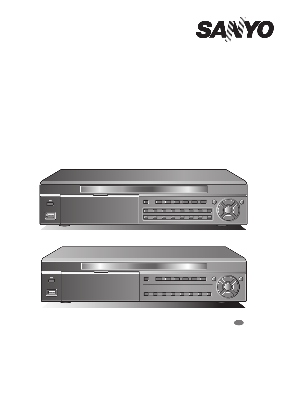
Digital Video Recorder
with Multiplexer Function
About this manual
Before installing and using this unit, please read this manual carefully.
Be sure to keep it handy for later reference.
DSR-2116
DSR-2108
DSR-2116
DSR-2108
GB
● Refer to the included CD-ROM for the German, French, Spanish and Italian “INSTRUCTION MANUAL”.
● Die “BEDIENUNGSANLEITUNG” in den Sprachen Deutsch, Französisch, Spanisch und Italienisch
finden Sie auf der beiliegenden CD-ROM.
● Utilisez le CD-ROM fourni pour consulter le “MANUEL D’INSTRUCTIONS” en allemand, français,
espagnol et italien.
● Consulte en el CD-ROM suministrado el “MANUAL DE INSTRUCCIONES” en alemán, francés, español e
italiano.
● Per il “MANUALE DI ISTRUZIONI” in Tedesco, Francese, Spagnolo e Italiano, fare riferimento al
CD-ROM allegato.
Page 2

Table of Contents
Safety precautions . . . . . . . . . . . . . . . . . . . . . . . . . . . . . . . . . . . . . ii
These precautions must be followed for safety reasons. . . . iii
Follow the points outlined below for proper use . . . . . . . . . . vi
Main Features . . . . . . . . . . . . . . . . . . . . . . . . . . . . . . . . . . . . . . . . . 1
Main parts replacement timings . . . . . . . . . . . . . . . . . . . . . . . . . . 1
Accessories . . . . . . . . . . . . . . . . . . . . . . . . . . . . . . . . . . . . . . . . . . 1
About the split screen display . . . . . . . . . . . . . . . . . . . . . . . . . . . 2
Names and functions of parts . . . . . . . . . . . . . . . . . . . . . . . . . . . . 3
Names of each part and connections. . . . . . . . . . . . . . . . . . . . . . 4
Basic connections. . . . . . . . . . . . . . . . . . . . . . . . . . . . . . . . . . . 4
Network connection (LAN) . . . . . . . . . . . . . . . . . . . . . . . . . . . . 5
Connecting to the RS-485 control terminal. . . . . . . . . . . . . . . 6
Switching the power on / off . . . . . . . . . . . . . . . . . . . . . . . . . . . . . 7
A Switching the power on . . . . . . . . . . . . . . . . . . . . . . . . . . . . 7
B Switching the power off . . . . . . . . . . . . . . . . . . . . . . . . . . . . 7
Pre-operation preparation . . . . . . . . . . . . . . . . . . . . . . . . . . . . . . . 8
Screen display . . . . . . . . . . . . . . . . . . . . . . . . . . . . . . . . . . . . . . 8
A Setting the television system and the monitor output . . . 9
B Setting the clock (CLOCK SET) . . . . . . . . . . . . . . . . . . . . . . 9
C Setting the language (LANGUAGE). . . . . . . . . . . . . . . . . . 11
D Setting the RS-485 termination switch
(SANYO SSP side). . . . . . . . . . . . . . . . . . . . . . . . . . . . . . . . 11
Monitoring the camera videos . . . . . . . . . . . . . . . . . . . . . . . . . . 12
A Single-screen display . . . . . . . . . . . . . . . . . . . . . . . . . . . . . 12
B Quad-screen display. . . . . . . . . . . . . . . . . . . . . . . . . . . . . . 12
C Multi-screen display . . . . . . . . . . . . . . . . . . . . . . . . . . . . . . 13
D Camera sequencing . . . . . . . . . . . . . . . . . . . . . . . . . . . . . . 13
Operating the PTZ dome camera . . . . . . . . . . . . . . . . . . . . . . . . 14
1 Connection. . . . . . . . . . . . . . . . . . . . . . . . . . . . . . . . . . . . . . 14
2 Settings . . . . . . . . . . . . . . . . . . . . . . . . . . . . . . . . . . . . . . . . 14
3 Operation . . . . . . . . . . . . . . . . . . . . . . . . . . . . . . . . . . . . . . . 14
Recording . . . . . . . . . . . . . . . . . . . . . . . . . . . . . . . . . . . . . . . . . . . 16
A Real time recording. . . . . . . . . . . . . . . . . . . . . . . . . . . . . . . 16
B CONTINUOUS recording. . . . . . . . . . . . . . . . . . . . . . . . . . . 17
C MOTION recording . . . . . . . . . . . . . . . . . . . . . . . . . . . . . . . 17
D ALARM recording . . . . . . . . . . . . . . . . . . . . . . . . . . . . . . . . 18
E SCHEDULE recording . . . . . . . . . . . . . . . . . . . . . . . . . . . . . 19
Playing back recorded videos. . . . . . . . . . . . . . . . . . . . . . . . . . . 21
A EVENT SEARCH . . . . . . . . . . . . . . . . . . . . . . . . . . . . . . . . . 22
B TIMELINE SEARCH . . . . . . . . . . . . . . . . . . . . . . . . . . . . . . . 23
C T/D SEARCH . . . . . . . . . . . . . . . . . . . . . . . . . . . . . . . . . . . . 24
D GO FIRST . . . . . . . . . . . . . . . . . . . . . . . . . . . . . . . . . . . . . . . 24
E GO LAST . . . . . . . . . . . . . . . . . . . . . . . . . . . . . . . . . . . . . . . 24
F LOG. . . . . . . . . . . . . . . . . . . . . . . . . . . . . . . . . . . . . . . . . . . . 24
G BOOKMARK. . . . . . . . . . . . . . . . . . . . . . . . . . . . . . . . . . . . . 25
Copying recorded video to recording media. . . . . . . . . . . . . . . 26
A Inserting recording media . . . . . . . . . . . . . . . . . . . . . . . . . 26
B Copying live videos. . . . . . . . . . . . . . . . . . . . . . . . . . . . . . . 26
C Copying a playback video . . . . . . . . . . . . . . . . . . . . . . . . . 27
D Playing back copied videos . . . . . . . . . . . . . . . . . . . . . . . . 27
Setting the security lock . . . . . . . . . . . . . . . . . . . . . . . . . . . . . . . 28
Configuration and function of the Menu settings . . . . . . . . . . . 29
LIVE settings. . . . . . . . . . . . . . . . . . . . . . . . . . . . . . . . . . . . . . . . . 31
A Setting the OSD and OSD CONTRAST . . . . . . . . . . . . . . . 31
B Setting the SEQUENCE and SEQUENCE-DWELL TIME . . .31
C Setting the EVENT BEEP . . . . . . . . . . . . . . . . . . . . . . . . . . 31
D Setting a CHANNEL. . . . . . . . . . . . . . . . . . . . . . . . . . . . . . . 32
E Alarm input output settings . . . . . . . . . . . . . . . . . . . . . . . . 32
F Setting the MON2 (Monitor2)-OUT. . . . . . . . . . . . . . . . . . . 33
RECORD settings. . . . . . . . . . . . . . . . . . . . . . . . . . . . . . . . . . . . . 35
A Setting the RESOLUTION . . . . . . . . . . . . . . . . . . . . . . . . . . 35
B Setting a CHANNEL. . . . . . . . . . . . . . . . . . . . . . . . . . . . . . . 35
C Setting the TIMER SET . . . . . . . . . . . . . . . . . . . . . . . . . . . . 36
D Setting the REAL-TIME RECSET . . . . . . . . . . . . . . . . . . . . 36
SYSTEM settings . . . . . . . . . . . . . . . . . . . . . . . . . . . . . . . . . . . . . 37
A Setting the DVR ID. . . . . . . . . . . . . . . . . . . . . . . . . . . . . . . . 37
B DESCRIPTION confirmation . . . . . . . . . . . . . . . . . . . . . . . . 37
C Setting the LOAD DEFAULT . . . . . . . . . . . . . . . . . . . . . . . . 37
D Setting an ADMIN PASSWORD . . . . . . . . . . . . . . . . . . . . . 38
E Setting the USER PASSWORD. . . . . . . . . . . . . . . . . . . . . . 39
F Setting a NETWORK PASSWORD . . . . . . . . . . . . . . . . . . . 39
G Setting the DATE FORMAT. . . . . . . . . . . . . . . . . . . . . . . . . 40
H Setting the CLOCK SET . . . . . . . . . . . . . . . . . . . . . . . . . . . 40
I Setting the RS485 SET . . . . . . . . . . . . . . . . . . . . . . . . . . . . 40
J Setting the PTZ CONTROL . . . . . . . . . . . . . . . . . . . . . . . . . 40
K Setting the LANGUAGE . . . . . . . . . . . . . . . . . . . . . . . . . . . 40
L Setting a REMOTE CONTROL ID . . . . . . . . . . . . . . . . . . . . 41
NETWORK settings . . . . . . . . . . . . . . . . . . . . . . . . . . . . . . . . . . . 42
A Setting the PORT. . . . . . . . . . . . . . . . . . . . . . . . . . . . . . . . . 42
B Setting a CLIENT ACCESS . . . . . . . . . . . . . . . . . . . . . . . . . 42
C Setting the BANDWIDTH SAVING . . . . . . . . . . . . . . . . . . . 42
D Setting the NETWORK TYPE . . . . . . . . . . . . . . . . . . . . . . . 43
E Setting the DDNS. . . . . . . . . . . . . . . . . . . . . . . . . . . . . . . . . 44
F Setting the SEND E-MAIL . . . . . . . . . . . . . . . . . . . . . . . . . . 45
G Setting the NTP SET . . . . . . . . . . . . . . . . . . . . . . . . . . . . . . 46
HDD SET settings. . . . . . . . . . . . . . . . . . . . . . . . . . . . . . . . . . . . . 47
A Setting the OVERWRITE . . . . . . . . . . . . . . . . . . . . . . . . . . . 47
B FORMAT settings . . . . . . . . . . . . . . . . . . . . . . . . . . . . . . . . 47
C Setting the auto delete function. . . . . . . . . . . . . . . . . . . . . 48
SERVICE settings. . . . . . . . . . . . . . . . . . . . . . . . . . . . . . . . . . . . . 49
A Setting the SAVE SETUP TO A USB . . . . . . . . . . . . . . . . . 49
B Setting the LOAD SETUP FROM A USB . . . . . . . . . . . . . . 49
C Displays the hard disk information . . . . . . . . . . . . . . . . . . 49
Operations using the Network . . . . . . . . . . . . . . . . . . . . . . . . . . 50
Connection and settings. . . . . . . . . . . . . . . . . . . . . . . . . . . . . 50
Operating environment . . . . . . . . . . . . . . . . . . . . . . . . . . . . . . 50
Installing "Sanyo DVR Utility 2000S" . . . . . . . . . . . . . . . . . . . 50
To uninstall the software. . . . . . . . . . . . . . . . . . . . . . . . . . . . . 51
Connecting to this unit . . . . . . . . . . . . . . . . . . . . . . . . . . . . . . . . 52
Main screen structure and function of each part . . . . . . . . . . . 53
Function of the operation panel . . . . . . . . . . . . . . . . . . . . . . . 54
Main screen basic operations . . . . . . . . . . . . . . . . . . . . . . . . . . . 55
A Switching the display mode of the screen . . . . . . . . . . . . 55
B Recording live video . . . . . . . . . . . . . . . . . . . . . . . . . . . . . . 56
C Freezing the live video . . . . . . . . . . . . . . . . . . . . . . . . . . . . 57
D The audio is output . . . . . . . . . . . . . . . . . . . . . . . . . . . . . . . 57
E Saving images . . . . . . . . . . . . . . . . . . . . . . . . . . . . . . . . . . . 57
F Operating the PTZ dome camera . . . . . . . . . . . . . . . . . . . . 58
Search mode operations . . . . . . . . . . . . . . . . . . . . . . . . . . . . . . . 59
A Searching and playing recorded video . . . . . . . . . . . . . . . 60
B Backing up DVR recorded video . . . . . . . . . . . . . . . . . . . . 61
Setup menu settings . . . . . . . . . . . . . . . . . . . . . . . . . . . . . . . . . . 62
A General settings (General) . . . . . . . . . . . . . . . . . . . . . . . . . 62
B Camera designation settings (Site) . . . . . . . . . . . . . . . . . . 63
C Event settings (Event). . . . . . . . . . . . . . . . . . . . . . . . . . . . . 64
D Event log search, view, save (Log View). . . . . . . . . . . . . . 64
E Record settings (Record) . . . . . . . . . . . . . . . . . . . . . . . . . . 65
F Disk settings (Disk) . . . . . . . . . . . . . . . . . . . . . . . . . . . . . . . 65
G Version information (About). . . . . . . . . . . . . . . . . . . . . . . . 65
Remote Setup . . . . . . . . . . . . . . . . . . . . . . . . . . . . . . . . . . . . . . . . 66
A Remote Setup operating procedure . . . . . . . . . . . . . . . . . 66
B Setting the Display . . . . . . . . . . . . . . . . . . . . . . . . . . . . . . . 67
C Setting the Alarm-Set . . . . . . . . . . . . . . . . . . . . . . . . . . . . . 68
D Setting the Monitor2 . . . . . . . . . . . . . . . . . . . . . . . . . . . . . . 69
E Setting the Record. . . . . . . . . . . . . . . . . . . . . . . . . . . . . . . . 70
F System settings. . . . . . . . . . . . . . . . . . . . . . . . . . . . . . . . . . 72
G Description. . . . . . . . . . . . . . . . . . . . . . . . . . . . . . . . . . . . . . 73
H Setting the PTZ Control . . . . . . . . . . . . . . . . . . . . . . . . . . . 73
I Setting the Network. . . . . . . . . . . . . . . . . . . . . . . . . . . . . . . 74
J Setting the Send E-Mail. . . . . . . . . . . . . . . . . . . . . . . . . . . . 75
K Setting the NTP . . . . . . . . . . . . . . . . . . . . . . . . . . . . . . . . . . 75
L Setting the Storage . . . . . . . . . . . . . . . . . . . . . . . . . . . . . . . 75
Operations using the Web browser . . . . . . . . . . . . . . . . . . . . . . 76
Part names of the remote control . . . . . . . . . . . . . . . . . . . . . . . . 79
Specifications. . . . . . . . . . . . . . . . . . . . . . . . . . . . . . . . . . . . . . . . 80
Mounting the hard disk (S-ATA) . . . . . . . . . . . . . . . . . . . . . . . . . 81
i
Page 3
Safety precautions
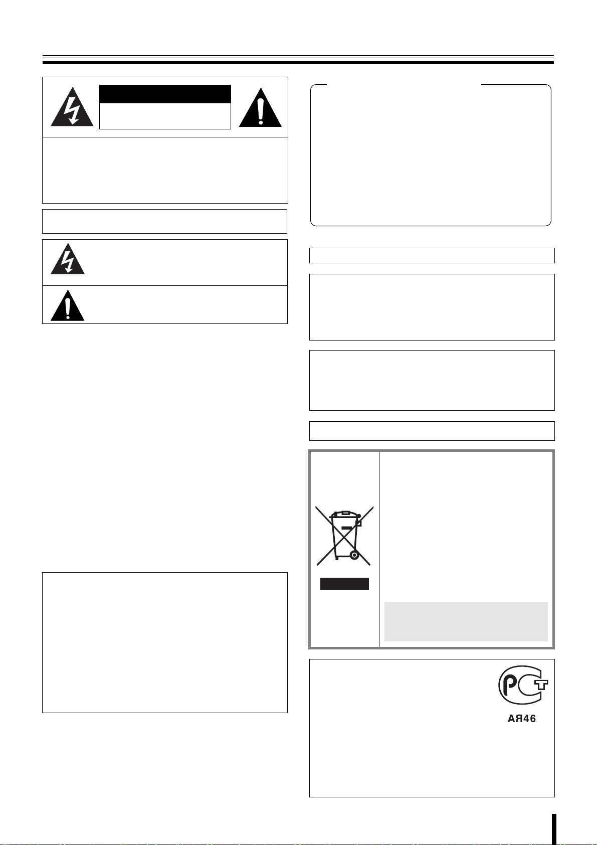
CAUTION
RISK OF ELECTRIC SHOCK
DO NOT OPEN
CAUTION: TO REDUCE A RISK OF ELECTRIC
SHOCK, DO NOT REMOVE COVER (OR BACK).
NO USER-SERVICEABLE PARTS INSIDE.
REFER SERVICING TO QUALIFIED SERVICE
PERSONNEL.
WARNING: To reduce a risk of fire or electric shock, do not expose
this product to rain or moisture.
The lightning flash with arrowhead symbol, within an
equilateral triangle, is intended to alert the user to the
presence of uninsulated “dangerous voltage” within the
product’s enclosure that may be of sufficient magnitude to
constitute a risk of electric shock to persons.
The exclamation point within an equilateral triangle is
intended to alert the user to the presence of important
operating and maintenance (servicing) instructions in the
literature accompanying the product.
CAUTION: Changes or modifications not expressly approved by the
manufacturer may void the user’s authority to operate this equipment.
This equipment has been tested and found to comply with the limits
for a Class B digital device, pursuant to Part 15 of the FCC Rules.
These limits are designed to provide reasonable protection against
harmful interference in a residential installation. This equipment
generates, uses and can radiate radio frequency energy and, if not
installed and used in accordance with the instructions, may cause
harmful interference to radio communications.
However, there is no guarantee that interference will not occur in a
particular installation.
If this equipment does cause harmful interference to radio or television
reception, which can be determined by turning the equipment off and
on, the user is encouraged to try to correct the interference by one or
more of the following measures.
• Reorient or relocate the receiving antenna.
• Increase the separation between the equipment and receiver.
• Connect the equipment into an outlet on a circuit different from
that to which the receiver is connected.
• Consult the dealer or an experienced radio/TV technician for help.
CAUTION
This product employs a Laser System.
To ensure proper use of this product, Please read this owner's
manual carefully and retain it for future reference.
Should the unit require maintenance, contact an authorized service
center.
Use of controls, adjustments or the performance of procedures
other than those specified herein may result in hazardous radiation
exposure.
To prevent direct exposure to laser beam, do not try to open the
enclosure. Visible laser radiation when open. DO NOT STARE
INTO BEAM.
Declaration of Conformity
Model Number : DSR-2116, DSR-2108
Trade Name : SANYO
Responsible party : SANYO FISHER COMPANY
Address : 21605 Plummer Street, Chatsworth, California
91311
Telephone No. : (818) 998-7322
• This device complies with Part 15 of the FCC Rules.
Operation is subject to the following two conditions:
(1) this device may not cause harmful interference,and
(2) this device must accept any interference received,
including interference that may cause undesired operation.
For the customers in Canada
This class B digital apparatus complies with Canadian ICES-003.
CAUTION
Danger of explosion if battery is incorrectly replaced.
Replace only with the same or equivalent type recommended by the
manufacturer.
Discard used batteries according to the manufacture’s instructions.
FOR CALIFORNIA, U.S.A. ONLY
This product contains a CR Coin Lithium Battery which
contains Perchlorate Material - special handling may apply.
See www.dtsc.ca/gov/hazardouswaste.perchlorate.
Licensed Under U.S. Patent No. 4,974,088
Please note:
Your SANYO product is designed and
manufactured with high quality materials and
components which can be recycled and
reused.
This symbol means that electrical and
electronic equipment, at their end-of-life,
should be disposed of separately from your
household waste.
Please dispose of this equipment at your local
community waste collection/recycling centre.
In the European Union there are separate
collection systems for used electrical and
electronic products.
Please help us to conserve the environment
we live in!
This symbol mark and recycle system
are applied only to EU countries and
not applied to the countries in the
other area of the world.
FOR RUSSIAN USERS
This product is certified by an official
certification company which is authorized by
the Russian Federation.
ДЛЯ ПОЛЬЗОВАТЕЛЕЙ
РОССИИ
Данная продукция сертифицирована
официальным органом по сертификации
Российской Федерации.
ii
Page 4
Safety precautions
These precautions must be followed for safety reasons.
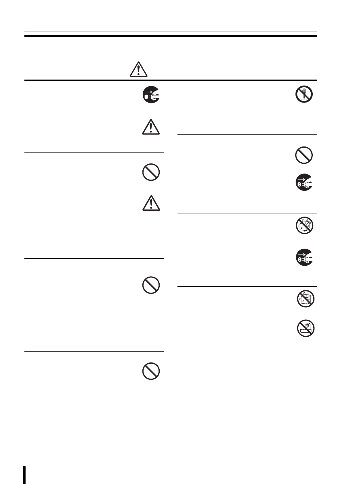
Warning
b Do not use if the unit emits smoke,
strange sounds are heard or odor is
emitted.
Continued use may cause electrocution and/
or fire. Immediately remove the power plug
Remove the power
plug from the outlet.
from the outlet. Once the unit stops emitting
smoke, consult the dealership where this unit
was purchased or factory shop for repairs.
Do not attempt repairs on your own.
b Make sure the power cable is not damaged.
• Always use the power cable supplied with
the unit.
• Do not place heavy objects on the power
cable or place the power cable near
Prohibited
heating equipment. Also, do not bend the
power cable forcefully, work upon or staple
it.
A damaged power cable may result in fire
and/or electrocution.
• Should the power cable become damaged
it must be replaced by the dealership
where this unit was purchased or factory
shop.
b Make sure there is no dust accumulation on the
power plug or the outlet.
• Dust accumulation may result in a
short-circuit and heat generation and
cause fire.
• Be especially careful when using an outlet
Prohibited
situated in a room exposed to high
humidity, condensation and/or dust, or in a
kitchen.
• Periodically remove the power plug from
the outlet and clean any dust and dirt
between the plug and the outlet.
b Caution when connecting the power cable
• Connect the power plug directly with the
outlet. Faulty connection may result in
heat generation and cause fire.
• Do not use the power cable while it is tied
in a bundle. This may result in heat
generation and cause fire.
• When using the extension cord supplied,
make sure the power consumption of the
connected unit does not exceed the
electrical rating of the extension cord.
Higher power consumption may result in
heat generation and cause fire.
Prohibited
b Disassembly prohibited
• Do not place your hand inside this unit as
this may cause fire and/or electrocution.
• Consult the dealership where this unit was
Disassembly
prohibited.
purchased or factory shop for diagnostics,
adjustments, and repairs.
b Do not place any foreign objects inside the unit.
• Do not insert or push in any metal or
combustible objects through openings
such as air ducts. This may cause fire and/
or electrocution.
Prohibited
• In the event that a foreign object is inside
the unit, turn off and unplug the unit.
Consult the dealership where this unit was
purchased or factory shop. Continued use
may result in fire and/or electrocution.
Remove the power
plug from the outlet.
b Do not place a container holding
water or other liquids above the unit
when it is connected to power.
In the event that water gets inside the unit,
turn off and unplug the unit. Consult the
dealership where this unit was purchased or
factory shop.
Continued use may result in a fire or
electrocution.
Water is prohibited
Remove the power
plug from the outlet.
b Do not allow the unit to get wet.
• This unit is not waterproof. Do not expose
the unit to water. This may cause fire and/
or electrocution.
Do not use in a bath or shower room.
• In the event that the internal components
have been exposed to water, turn the
power off and remove the power plug from
the outlet. Consult the dealership where
this unit was purchased or factory shop.
Continued use may cause electrocution
and/or fire.
Water is prohibited
Exposing to water
is prohibited
iii
Page 5
Safety precautions
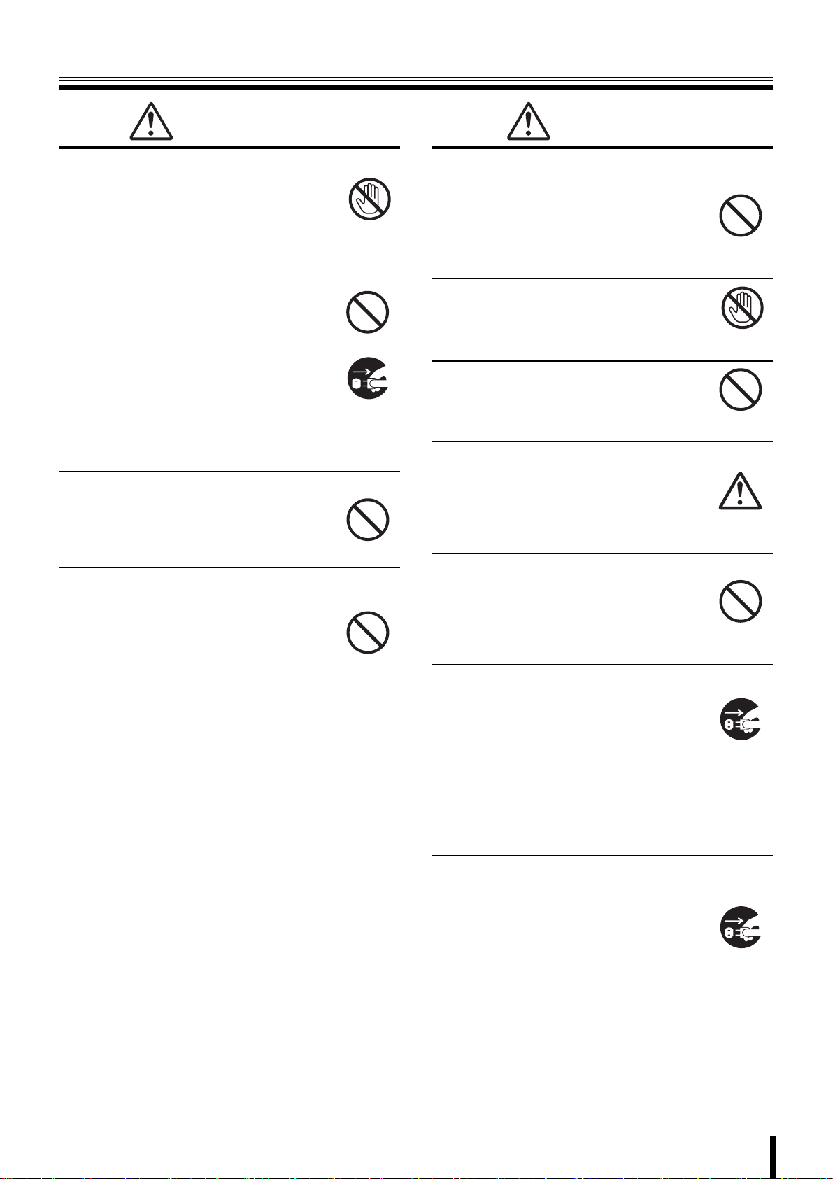
Warning
b Do not use during thunder/thunder storms.
Do not use during thunder/thunder storms.
Never touch the connection cable during
thunder/thunder storms. This may cause
electrocution.
b Do not place in an unstable position.
• Doing so may cause accidents and/or
breakdowns through falling or toppling.
• In the event that the unit has been
dropped or the casing has been damaged,
turn the power off and remove the power
plug from the outlet. Consult the
dealership where this unit was purchased
or factory shop.
Continued use may cause electrocution
and fire.
b Do not expose to shock or vibration.
Stored data may be damaged or lost through
hard-disk breakdowns caused by shock/
vibration.
b Do not use this unit in areas where it is exposed
to the possibility of explosion.
Do not use this unit in areas where explosive
and/or flammable gases are present. This
may cause fire and/or explosion.
Contact prohibited
Prohibited
Remove the power
plug from the outlet.
Prohibited
Prohibited
Caution
b Do not pull on the power cable when removing
the power plug from the outlet.
Hold the power plug when disconnecting the
power cable from the outlet. Pulling on the
power cable may damage the cord. This may
cause fire and/or electrocution.
b Do not touch the power plug with wet
hands.
Doing so may result in electrocution.
b Do not sit on.
Doing so may cause the unit to fall, be
damaged and/or result in injury.
b Make sure the cables are connected properly.
Connect and install the power cable and
connection cable very carefully. Tripping over
the cable may result in the unit capsizing or
falling and cause injury.
b Do not place heavy objects on connected units.
Doing so may affect the stability of the unit
and cause it to fall which may result in injury.
Doing so may also damage the unit
depending on the weight of the object.
b Shipment and portability
• Never move this unit while the power is
turned on.
• When shipping, remove the power plug
from the outlet, confirm that the
connection cable has been removed, and
store in original packaging. Ship using a
method that causes the least amount of
shock and/or damage to this unit. Also, do
not drop this unit.
Prohibited
Wet hands
prohibited
Prohibited
Prohibited
Remove the power
plug from the outlet.
b Maintenance when the unit is going to remain
unused for long periods of time
Remove the power plug from the outlet.
Carrying out maintenance without removing
the power plug may cause electrocution.
Remove the power
plug from the outlet.
iv
Page 6
Safety precautions
Caution
b Cleaning the internal components
Consult the dealership where this unit was
purchased or factory shop for cleaning
internal components. Leaving the unit unused
for long periods of time may attract dust to the
internal components, which in turn may
cause fire and/or breakdowns.
b Do not block the cooling fans or air ducts.
• This unit is equipped with air ducts and
cooling fans in order to assist the
ventilation of hot air produced by the hard
disk drive.
Placing covers, placing in a case, or
placing inside bookcases may cause heat
build up, and may result in fire and/or
electrocution.
b When the unit is set up in a rack
The hard disk drive and so on generates heat, which may
cause operation errors and damage, therefore leave the
specified open spaces when setting up the unit. Also, use
only an open framed rack without back panels.
• Leave the specified open space between the unit and
the rack
• Leave 1 cm or more on the upper and lower side
• Leave 5 cm or more on both sides
• Leave open space of 10 cm or more between the rear
of the rack and the wall
b Cautionary points on condensation
Droplets may form on the outside when very cold water is
poured into a cup. In the same way, droplets may form
around the internal components of this unit. This is called
condensation.
Do not use this unit if condensation has formed.
Using this unit while condensation is formed may cause
breakdowns. In the event of sudden sharp temperature
changes, turn off the power and do not use this unit until
the temperature of the room where it is positioned
stabilizes (about 2 hours).
Condensation will not occur while the power is turned on.
Prohibited
When condensation is likely to occur ...
Use the unit after turning the power off and leaving it for
1~2 hours.
b Do not expose to extreme temperatures or
humidity changes.
• Do not place in areas where the unit will
be exposed to extreme temperatures
(±10 degrees C per hour) or humidity
changes.
b Points on unit positioning
This unit is constructed using precision
electronic parts. Avoid placing it in areas
described below as this may cause faulty
operation and/or breakdowns.
• In direct sunlight
• In places exposed to water
• In the vicinity of cooling and heating units or humidifiers
• Near the air conditioner where the unit is exposed to
cool air
• Dusty areas
• Areas that contain fire hazards
• Areas that contain magnetic items
• In the vicinity of volatile substances
• Areas where the unit will be exposed to constant
vibration (in trains, cars, etc.)
Prohibited
Prohibited
v
Page 7
Safety precautions
Follow the points outlined below for proper use
bBack up battery.
• This unit has got a built-in lithium battery used to back
up the clock function. The battery continues to operate
the clock even when there is a power disruption.
• The life expectancy of the battery is approximately 2
years. If the battery runs out or leaks, the clock resets
when the power is turned off. When the power is turned
back on (or when rebooted), a warning message to
replace the battery is displayed on the monitor screen.
Consult the dealership where this unit was purchased
or a "Repair Service Center".
Battery fluid leaks
In the event that the battery fluid has leaked rinse hands/
clothes thoroughly with water.
Loss of eyesight may result if battery fluid enters the eyes.
Do not rub the eyes. Immediately rinse with clean water
and consult a physician.
When disposing of this unit
Consult the dealership where this unit was purchased for
information concerning the disposal of the lithium battery.
CAUTION:
RISK OF EXPLOSION IF BATTERY IS REPLACED BY AN
INCORRECT TYPE.
DISPOSE OF USED BATTERIES ACCORDING TO THE
INSTRUCTIONS
bIf unused for a lengthy period of time
Remove the power plug from the outlet. Remember to
occasionally turn the power on in order to maintain correct
function.
bPre-confirm important recording
assignments
Recording and/or playback functions may be unavailable
due to hard-drive or connecting unit failures. Always
confirm that recording can be carried out successfully
before carrying out important recording assignments.
The recorded content cannot be guaranteed.
It is recommended to periodically back up data in order to
prevent the loss of the data in the event of breakdowns,
recording faults or accidents.
bMaintaining this unit
Turn the power off and remove the power plug from
the outlet. Wipe away any dust using a soft cloth.
When the stains are hard to remove...
Soak a cloth in water with diluted neutral detergent
and wring it. Wipe the stain with the moistened cloth
and finally dry off with a dry cloth.
CAUTION:
• Do not use paint thinner, benzine, or any other alcohol
based agents for cleaning. The exterior may deteriorate
or the paint may wear off.
• Follow the instructions supplied on the packaging of the
chemical cleaning agent.
• Do not spray volatile substances, such as insecticides,
etc. onto the unit. Also, avoid extended contact with
rubber or vinyl products.
This may cause exterior damage or wear the paint off.
bCopyright information
• This manual and software are copyrighted to SANYO
Electric Co., Ltd.
• Microsoft, Windows and Internet Explorer are
trademarks or registered trademarks of Microsoft USA
in the USA and in other countries.
• Intel and Pentium is a trademark or registered
trademark of Intel USA in the USA and in other
countries.
• Brand and product names used in this manual are the
trademarks or registered trademarks of their respective
companies.
Except for personal use, copyright law prohibits the use of
recorded copyrighted images without the permission of the
copyright holder.
bPersonal data protection
Images or footage recorded by the camera video system in
which people are captured and can be identified are
considered to be personal information and fall within the
scope of the Personal Data Protection Law. It is the
responsibility of the user to operate the system in
accordance with the above law.
vi
Page 8
Main Features
Accessories
• Long-time MPEG4 recording
• Moving video monitoring in split screen
• Coaxial superimposed type (COAX) camera
control
• Maximum recording speed
DSR-2116: 240 IPS (NTSC) or 200 IPS (PAL)
DSR-2108: 120 IPS (NTSC) or 100 IPS (PAL)
• 4ch audio recording
• Image downloading to USB memory
• Remote operation from PC via network
• VGA video output
• Built-in disc drive (DVD-R or CD-R/RW)
• Comes with IR remote control and DVR utility
software
Main parts
replacement timings
Continued use of this unit in a 25°C environment may result in
wear and deterioration of the parts of the unit.
We recommend you replace the following parts according to
the timings listed below. The replacement timings listed are
approximate and do not guarantee the performance of the
part in question.
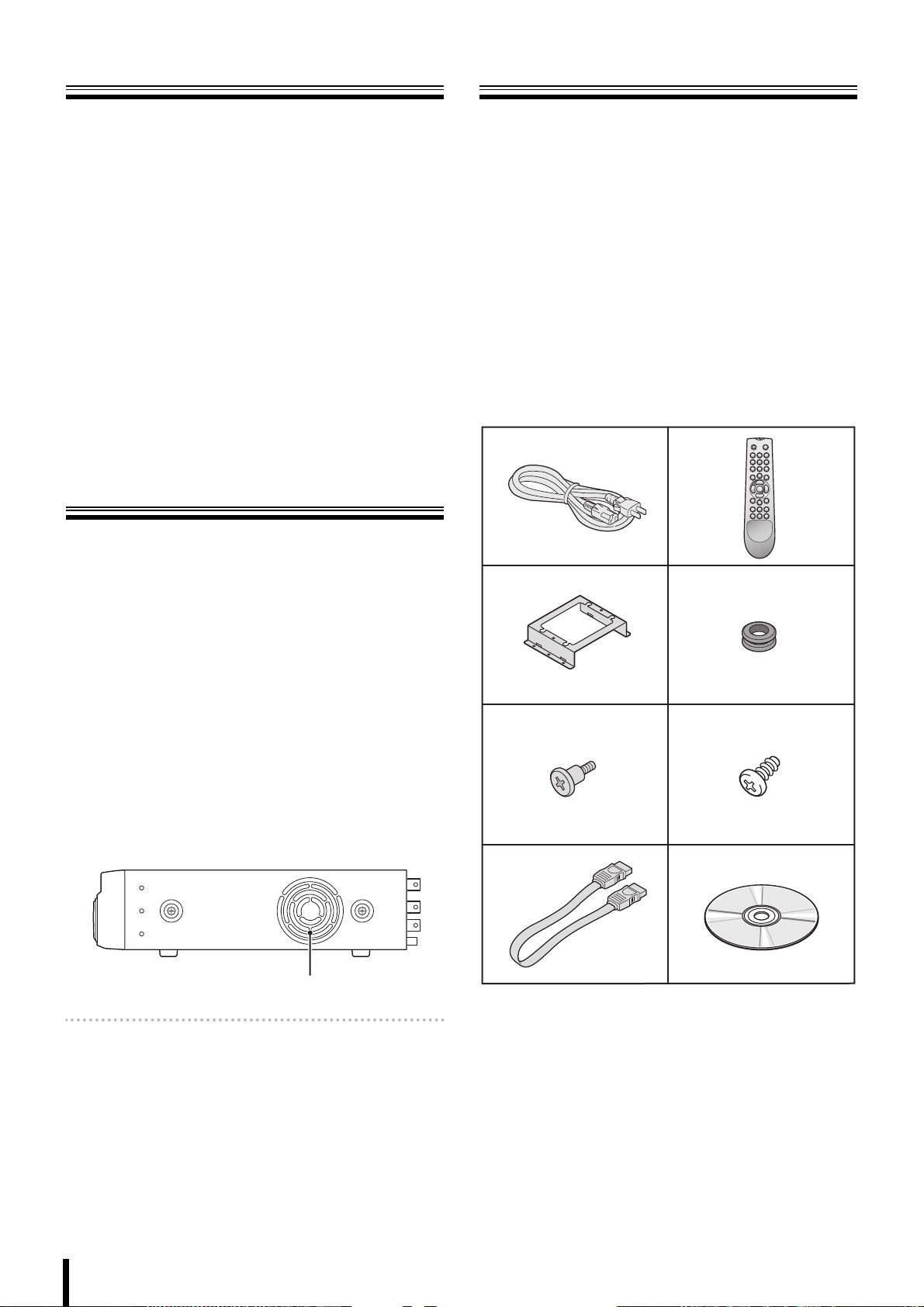
Check that all the parts shown below are supplied.
1 Power cable (×2)
2 Remote control
*2 “AAA” batteries are necessary for the remote control.
(Batteries not included)
3 HDD mounting bracket (×2)
4 Rubber pad (×8)
5 Mounting bracket screws (×8)
6 HDD fixing screw (×8)
7 S-ATA cable (×2)
8 CD-ROM
• Instruction Manual (Digital Video Recorder)
12
34
b Hard disk: 2 years (25°C environment)
The life expectancy of each part depends on the
environment in which the unit is used. However, the head
and motor are particularly prone to wear and deterioration.
Therefore, writing errors are more likely to occur after two
years of use.
b Cooling fan: 3 years (25°C environment)
Cooling fan failure causes higher internal temperatures
which may result in a faulty hard disk. Periodically check
whether the cooling fan is working properly.
Cooling fan
Memo: This unit is equipped with two cooling fans on the
right and at the rear. The cooling fan on the right may
be replaced.
b Battery: 2 years (25°C environment)
56
7
8
1
Page 9

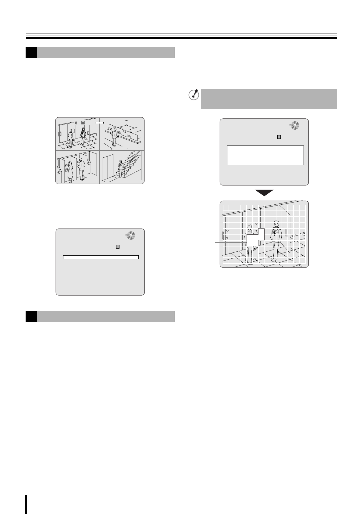
About the split
screen display
This manual is common to 2 models. Major differences
between these two models are, the number of channel
selection buttons available on the front panel and the number
of input/output terminals available on the rear panel.
As a result, the number of split screens that can be displayed
on the monitor is different, as shown below.
(DSR-2116) (DSR-2108)
Warning
The hard disk is a precision instrument. To avoid damage,
handle the hard disk with care and do not expose it to shock.
Do not block the ventilation holes and do not allow the cooling
fan to stop. Doing so may cause heat build up and may
shorten the life expectancy of the hard disk.
G This unit is designed to be positioned horizontally. Do
not position vertically.
G Do not expose to shock or vibration and do not
transport while power is turned on.
Always turn the power off when moving in and out of racks
or other shelves.
G Do not remove the power plug while recording or
playing images back.
G Do not move the unit for approximately 30 seconds
after turning the power off.
The hard disk continues to rotate for a short duration after
the power has been turned off. The unit is further
susceptible to damage through shock and vibration during
that period. It is imperative that you do not move the unit
during that time.
G Do not expose to shock or vibration.
Avoid placing this unit directly on the floor. Make sure that
the four stands attached to the base of this unit are used
when placing it on the floor.
G Always use the original packaging (packaging
supplied at the time of purchase), when shipping the
unit.
Make sure you use the packaging materials supplied at the
time of the original purchase when shipping the unit or a
single internal component of the unit. Select a shipping
method that will cause the least amount of shock to the
unit during shipping.
Consult the dealership where this unit was
purchased for hard disk replacement.
• The hard disk is vulnerable to static electric shocks. Take
appropriate measures to prevent exposure to static
electricity.
• Unpackaged drives should be placed horizontally with their
base plate facing upwards on top of a soft cloth. Exposing
the hard disk to shocks and vibration may cause
breakdowns.
• Do not expose the drive to shocks and/or vibrations when
removing/tightening the screws at the time of hard disk
replacement. Firmly tighten the screws after replacement.
2
Page 10
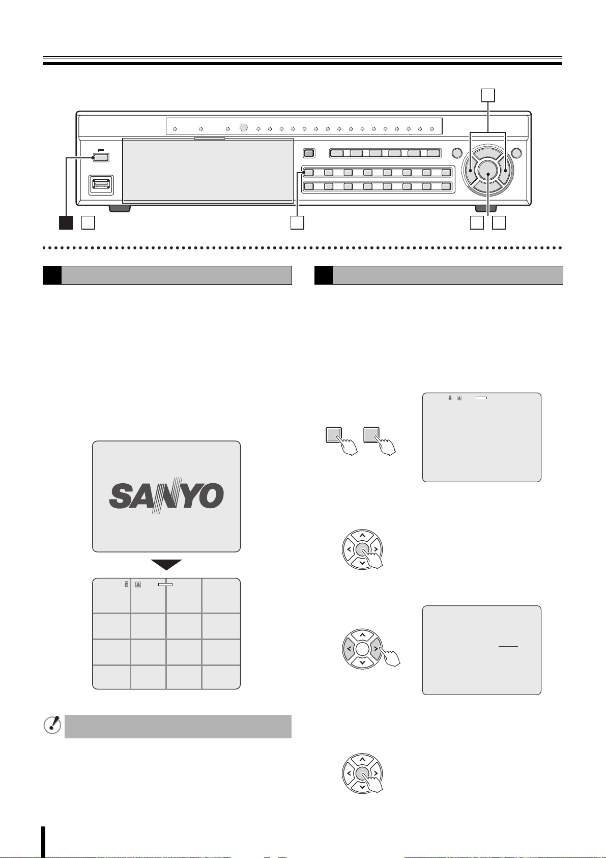
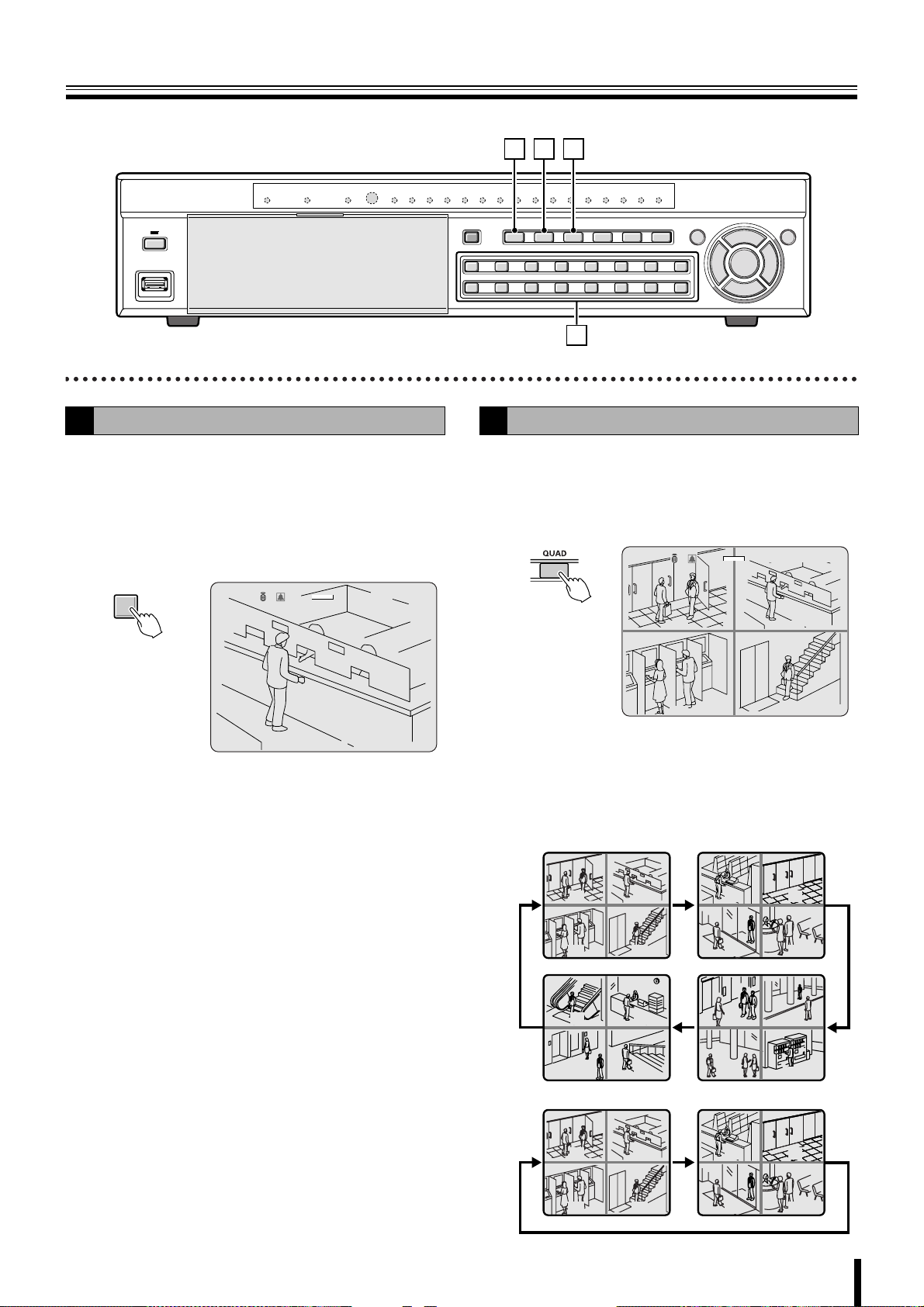
Names and functions of parts
B
Front panel
(DSR-2116)
1
2
4 5 6 7 8 9FGHIJ L M
3K
N
1 Power button and indicator ( )
2 USB terminal (USB) (Exclusively for 2.0) (P26)
To save video, connect a USB memory.
3 Disc drive
To save video, insert a DVD-R or CD-R/RW.
To open and close the insert tray, open the panel and
press the button.
4 LAN indicator (LAN)
The indicator blinks when the unit is connected and used
through the LAN cable.
5 Alarm indicator (ALARM)
The indicator lights when an alarm is set off.
6 Hard disk drive indicator (HDD)
The indicator lights when the hard disk is being accessed.
7 Recording indicator
The channel number being recorded lights.
8 Record/Stop button (REC/STOP) (P16)
Starts/Stops the recording of the monitored live image
displayed.
9 Automatic camera scrolling button (SEQ) (P13)
Automatically switches through and displays the images of
each live.
F Quad-screen display button (QUAD) (P13)
The monitor video is displayed on quad-screen.
G Multi button (MULTI) (P13)
The monitor video is displayed on multi-16 or multi-9
screen.
☞ In DSR-2108, the monitor video is displayed on
multi-8 screen.
H Mark/Copy button (MARK/COPY) (P26)
Switches to image saving mode.
I Search button (SEARCH) (P22)
Switches to recorded-images searching mode.
J Pan/Tilt/Zoom button (PTZ) (P14)
Operates the Pan/Tilt/Zoom/Focus mode of the PTZ dome
camera.
K Camera channel selection buttons (P12)
The video of the selected channel is displayed on
single-screen.
Also used to enter a password.
(DSR-2108)
L Menu button (MENU) (P9/30)
Displays the settings menu screen and switches to setting
mode.
M Exit/Stop button (EXIT/STOP) (P17)
During settings: Returns to the previous screen.
During playback: Interrupts playback operation.
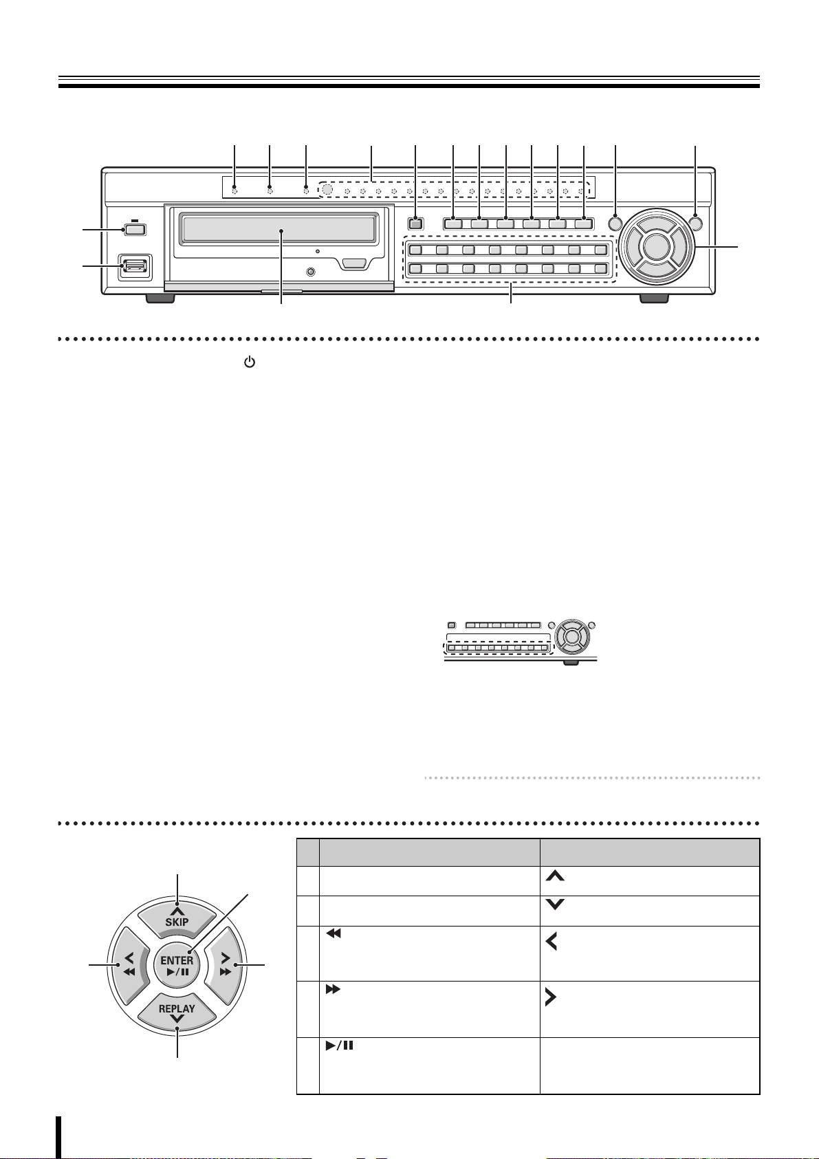
N Control button
C
3
A
E
D
Memo: A security lock can be set by holding the button
down. (P28)
Playback in progress
Skip button (SKIP):
A
The player jumps one minute forward.
Replay button (REPLAY):
B
The player jumps one minute backward.:Moves the cursor downward.
button:
The player fast rewinds.
C
button:
The player fast-forwards.
D
button:
The player displays a still image.
E
Plays the image selected during the image
search operation.
Moves the cursor upward.
Changes the settings value or moves the
cursor to the left.
Changes the settings value or moves the
cursor to the right.
ENTER :
Sets the selected item or displays the
settings screen.
Setting in progress
(Cursor operation)
:
:
:
Page 11
Names of each part and connections
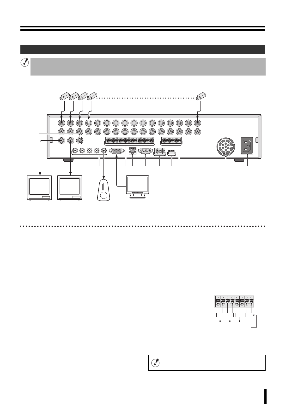
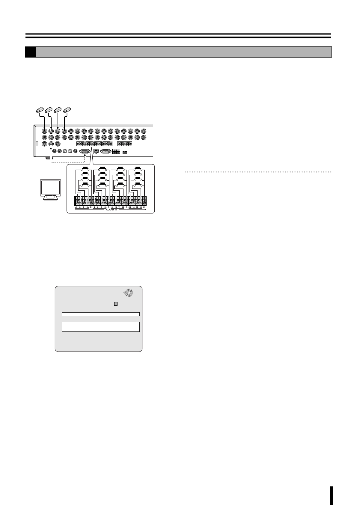
Rear panel
Basic connections
• Do not turn this unit on before all the connections are complete. Read the instruction manual of each unit carefully.
• Make sure each unit is connected properly as faulty connection may result in the unit emitting smoke and/or being damaged.
• Feed additional units with the same power source. Stored data may be lost.
Camera
(Sold separately)
1
2
3
Video monitor
(Sold
separately)
4
Video monitor
(Sold
separately)
56789FGH I J
Speaker with
built-in amplifier
(Sold separately)
1 Video input terminal (VIDEO IN/LOOP OUT)
2 Video output terminal (S-VIDEO)
3 Monitor 2 video output terminal (MON2)
4 Video output terminal (MAIN)
5 Audio input/output terminal (AUDIO IN: CH1 - CH4/
OUT1)
6 VGA (Video Graphics Array) output terminal
Connects to the PC VGA monitor.
7 External sensor terminal (ALARM IN)
8 Network terminal (LAN: P5)
9 RS-232C terminal (RS-232C)
For maintenance purposes.
F RS-485 control terminal (RS-485: P6)
MENU
POWERMODEAUTO
Monitor
(Sold
separately)
G System changeover switch (SWITCH)
TERMINATE: RS-485 termination switch (P11)
RSV: For maintenance purposes.
VGA: Monitor selection switch (P9)
PA L: Television mode (PAL/NTSC) switching switch (P9)
H Alarm output terminal (ALARM OUT: CH1 - CH4)
When the configured alarm output conditions are met, a
relay signal is output to one or more external alarm
devices connected to the alarm output terminals. These
terminals are normally open.
Maximum current: 0.5 A/125 VAC
Maximum voltage: 1 A /30 VDC
Power supply
External alarm device 1 - 4
1234
I Cooling fan
J Power socket
This equipment is indoor use and all the ethernet
wiring are limited to inside of the building.
4
Page 12
Names of each part and connections
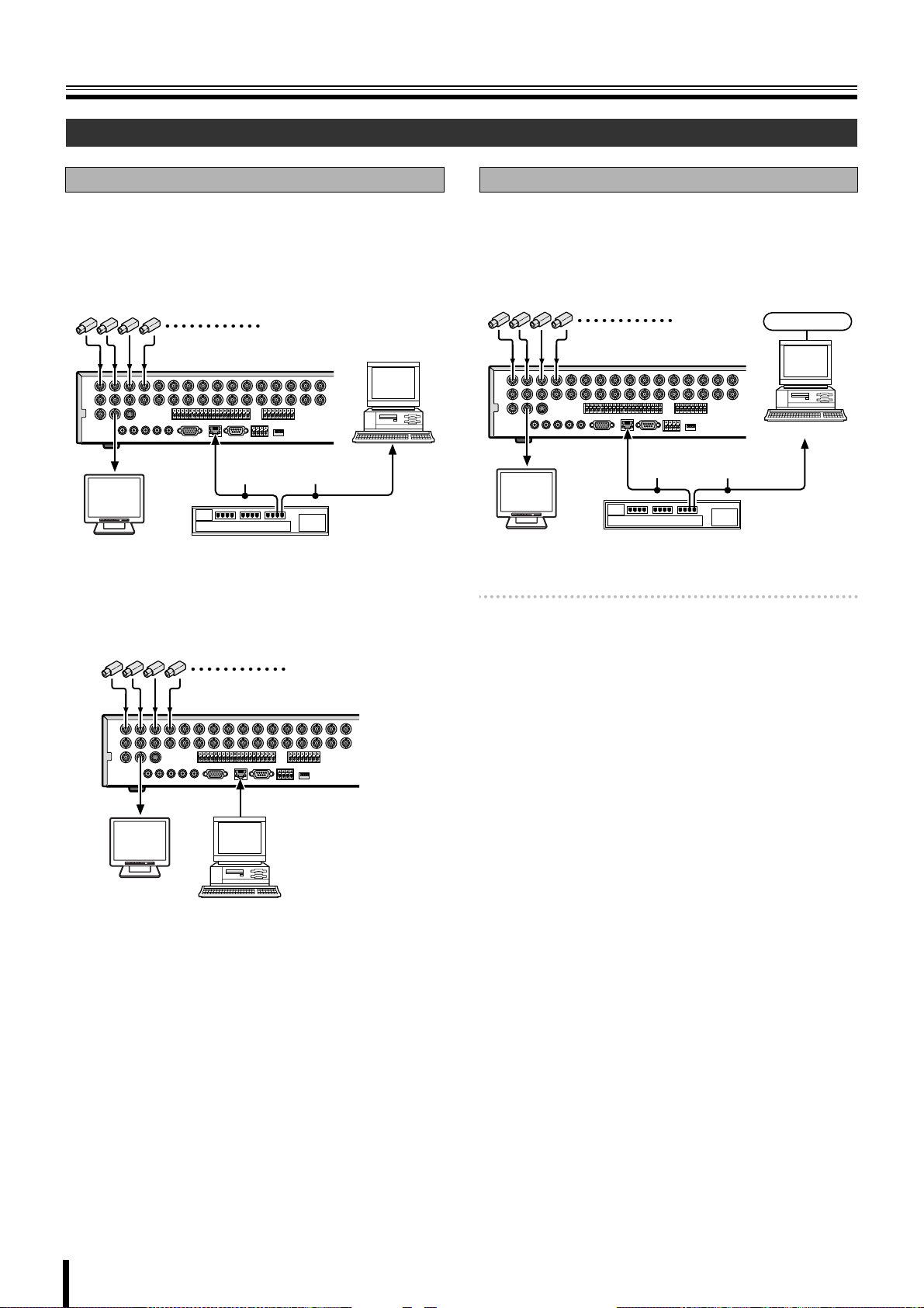
Network connection (LAN)
LAN connection
b Using the switching hub
Use a 10BASE-T/100BASE-TX CAT 5 LAN cable.
When controlling the network, connect to hubs such as the
switching hub using an Ethernet cable.
Camera
(Sold separately)
Computer
Ethernet cable
(Straight cable)
POWERMODEAUTOMENU
Monitor
(Sold separately)
Switching hub
b Without using a switching hub
Camera (Sold separately)
Internet (DHCP, ADSL) connection
Connect to the Internet using a router and the like.
When connecting to an ADSL modem or other device, read
the instruction manual of the device for information on how to
connect.
Camera
(Sold separately)
Internet
Computer
Ethernet cable
(Straight cable)
POWERMODEAUTOMENU
Monitor
(Sold separately)
Memo: The type of network must be set on the NETWORK
screen. (P42)
Router or ADSL modem
and the like
POWERMODEAUTOMENU
Monitor
(Sold separately)
Cross type
Computer
5
Page 13
Names of each part and connections
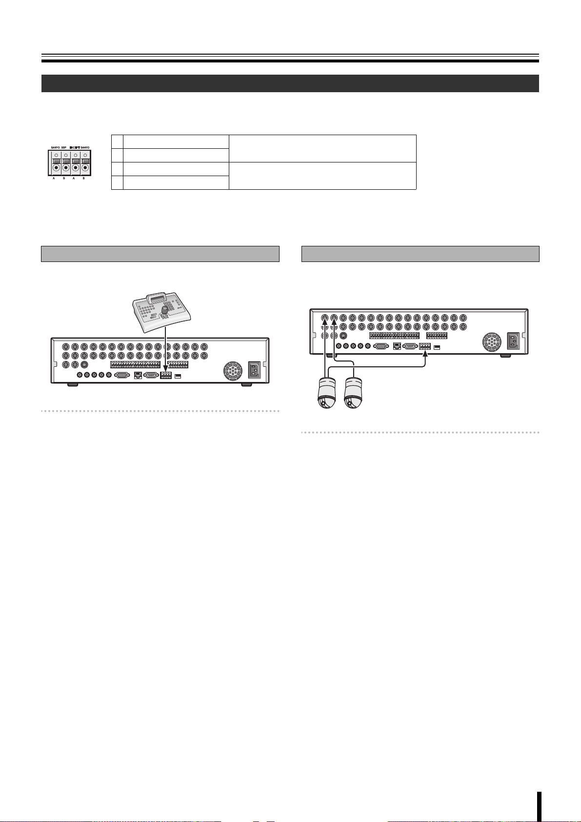
Connecting to the RS-485 control terminal
Remote systems such as system controllers and PTZ dome cameras are connected to the RS-485 control terminal.
Check the manufacturer of the units to be connected and connect the units to the appropriate terminal signals (A/B).
1234
RS-485/422
1 A (SANYO SSP)
2 B (SANYO SSP)
3 A (EXCEPT SANYO)
4 B (EXCEPT SANYO)
To connect a Sanyo PTZ dome camera or
system (SANYO SSP) controller
To connect a third-party camera
If a system controller is connected
This unit can be operated through the controller.
System controller
Memo: • The setting of the RS-485 screen on the system
setting is necessary when a system controller is
connected. (P40)
• Refer to the System controller’s instruction manual
for more information about the operation method.
If a camera is connected
If a PTZ dome camera equipped with a RS-485 control
terminal is connected, the camera can be directly operated
through this unit.
Memo: The settings on the PTZ CONTROL screen and
RS-485 SET screen in the system setting are
necessary when a camera is connected. (P14, 40)
• Connection to the RS-485 control terminal is
unnecessary for coaxial superimposed type
(COAX) cameras. Select a protocol for COAX in the
PTZ CONTROL settings. (P14)
6
Page 14
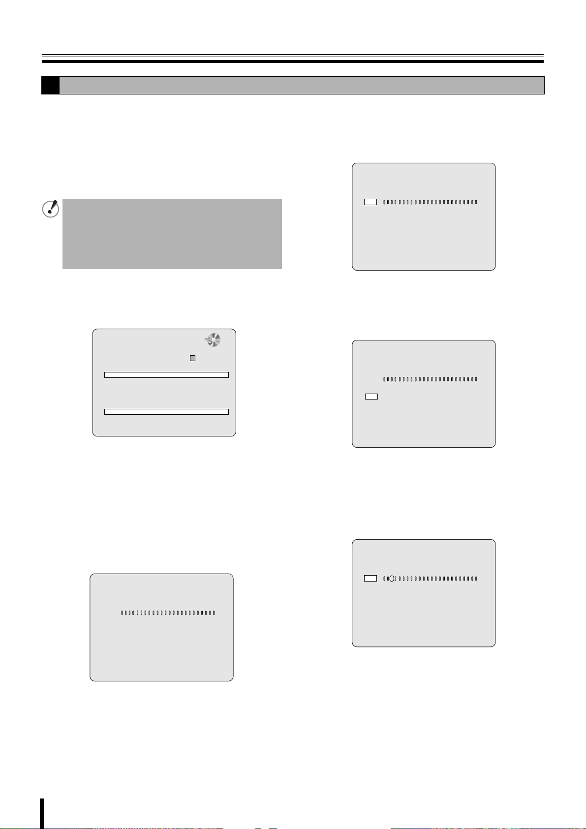
Switching the power on / off
4
Switching the power on
A
Connect the power cable to the outlet.
1
Turn on the electricity, the power indicator lights in
orange (standby).
Press the power button.
2
The power indicator changes to green (running) and
initialization starts.
During initialization the message "INITIALIZING..." and
the firmware version are displayed on a "SANYO" logo
screen.
Once the initialization is complete, live videos are
displayed on multi-16 screen.
INTIALIZING...
Ver: SNXXXX.XX.XXXX(YYYYMMDD)
212 53
Switching the power off
B
Press the power button.
1
The password entering screen is displayed.
Enter the ADMIN PASSWORD using the channel
2
selection buttons.
The factory default password is "1111".
For security reasons, make sure you change the default
ADMIN PASSWORD. (P38)
:A
1 10
~
Press the ENTER button.
3
The SHUTDOWN confirmation screen is displayed.
PASSWORD
* * * *
- - - -
CH1
•
2%
2009/05/03 09:04:54
2%
:A
NO VIDEO
C
CH1
NO VIDEO
CH5
NO VIDEO
CH9
NO VIDEO
CH13
Do not press the power button during initialization. This
may result in data loss.
CH2
NO VIDEO
CH6
NO VIDEO
CH10
NO VIDEO
CH14
2009/05/03 09:04:54
NO VIDEO
CH3
NO VIDEO
CH7
NO VIDEO
CH11
NO VIDEO
CH15
NO VIDEO
CH4
NO VIDEO
CH8
NO VIDEO
CH12
NO VIDEO
CH16
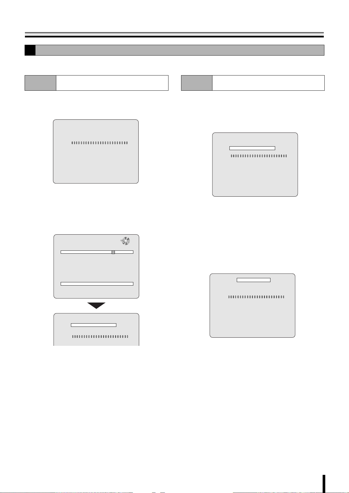
7
Select "CONFIRM" with the control button (}~).
4
SHUTDOWN
CANCEL CONFIRM
Press the ENTER button.
5
The power shuts down and the power indicator turns
orange.
Page 15
Pre-operation preparation
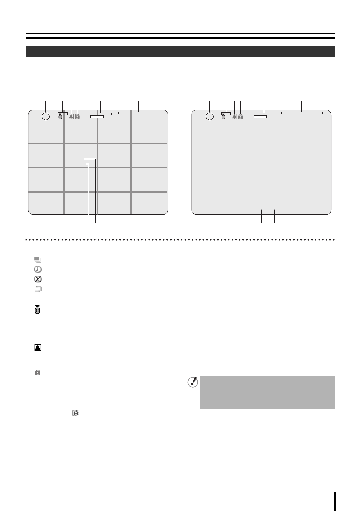
Screen display
Upon turning the power on, live video is displayed in the multi screen format.
• The screen display can be hidden except for the recording screen display. (P31)
b Example of multi-16 screen b Example of single-screen
12 634 5
2%
2009/05/03 09:04:54
CH3
CH11
CH15
CH4
CH12
CH16
CH1
CH9
CH13
:A
CH2
C
CH6CH5 CH7 CH8
CH10
CH14
78
1 Operation display
: Displayed during live video sequencing.
: Displayed during alarm output.
: Displayed when the alarm output is set to DISABLE.
: Displayed during remote operation by PC.
2 Remote control display (P41)
: Displays the remote control ID currently in
:A
operation.
If no remote ID is set the message "A(all)" is
displayed.
3 Alarm input display
: Turns red during an alarm recording triggered by
motion or external alarm input (ALARM IN).
4 Security lock display
: Displayed when setting the security lock. (P28)
5 Hard disk used capacity display
Displays the amount of recording on the hard disk from
0-99%. When the disk is full, "99%" changes to "FULL".
When the recording setting is set to overwriting and the
hard disk is full, to the left of the capacity display lights
to indicate that the unit is in the overwriting mode.
12 634 5
2%
:A
CH1
2009/05/03 09:04:54
C
78
6 Date and time display
This unit manages the recorded videos according to their
date and time. Make sure the correct date and time are set
in the CLOCK SET. (P9)
7 Camera channel display
Select display/hide channel in "OSD" in "LIVE settings".
(P31)
8 Recording display
Factory default settings start continuous recordings (C)
automatically once the power is turned on. Change the
recording mode using the menu settings. (P35)
C: Recording in the continuous mode (CONTINUOUS)
R: Recording in the real time mode (When pressing the
REC/STOP button)
M: Recording in the motion detection mode (MOTION)
A: Recording in the ALARM IN detection mode (ALARM)
• If a live video is disconnected, the message "VIDEO
LOSS" is displayed on the monitor.
• If a video signal is not connected to the video input
terminal, the message "NO VIDEO" is displayed on
the monitor.
8
Page 16
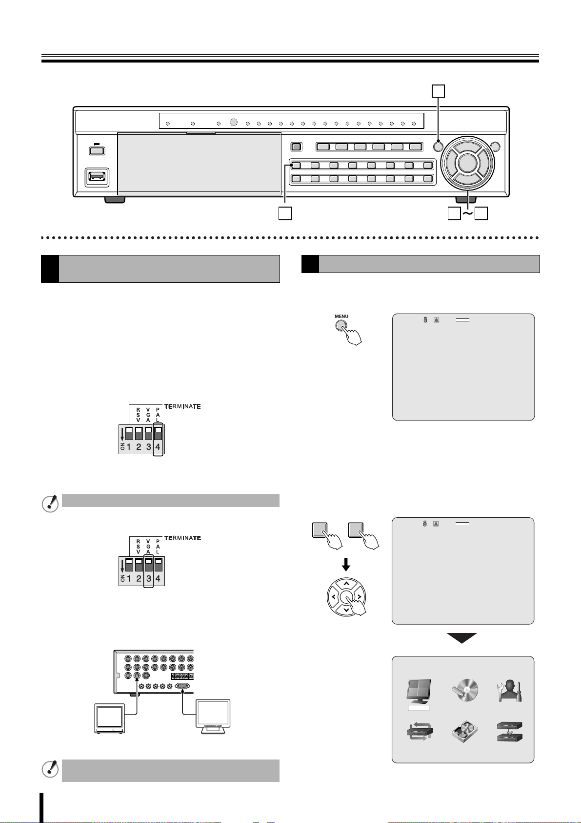
Pre-operation preparation
1
Setting the television system and the monitor
A
output
If the television system of the camera to be connected and
the type of monitor differ, live videos cannot be monitored on
the normal screen. Check the specifications of the equipment
to be connected and set the system changeover switch on the
rear panel.
• Do not forget to turn off the power when adjusting the
settings.
b Matching the television system of the camera
(PAL)
Up: When using a NTSC camera
Down: When using a PAL camera
Cannot be used when PAL and NTSC system are mixed.
2 3
Setting the clock (CLOCK SET)
B
Press the MENU button.
1
The PASSWORD input screen is displayed.
:A
PASSWORD
• To return to the previous screen, press the EXIT/
STOP button.
Enter the "ADMIN PASSWORD" using the channel
2
selection buttons.
The MAIN MENU screen is displayed.
•"1111" is the factory default setting password.
- - - -
CH1
9
2%
2009/05/03 09:04:54
b Selecting the type of monitor (VGA)
Up: When connecting the general monitor to the video
output terminal
Down: When connecting a PC monitor to the VGA
terminal
POWERMODEAUTOMENU
Generic monitors PC monitors
The VGA terminal and the video output terminal cannot
be used simultaneously.
9
1 10
~
:A
PASSWORD
* * * *
- - - -
CH1
MAIN MENU
RECORDLIVE SYSTEM
HDD SETNETWORK SERVICE
2%
2009/05/03 09:04:54
Page 17
Pre-operation preparation
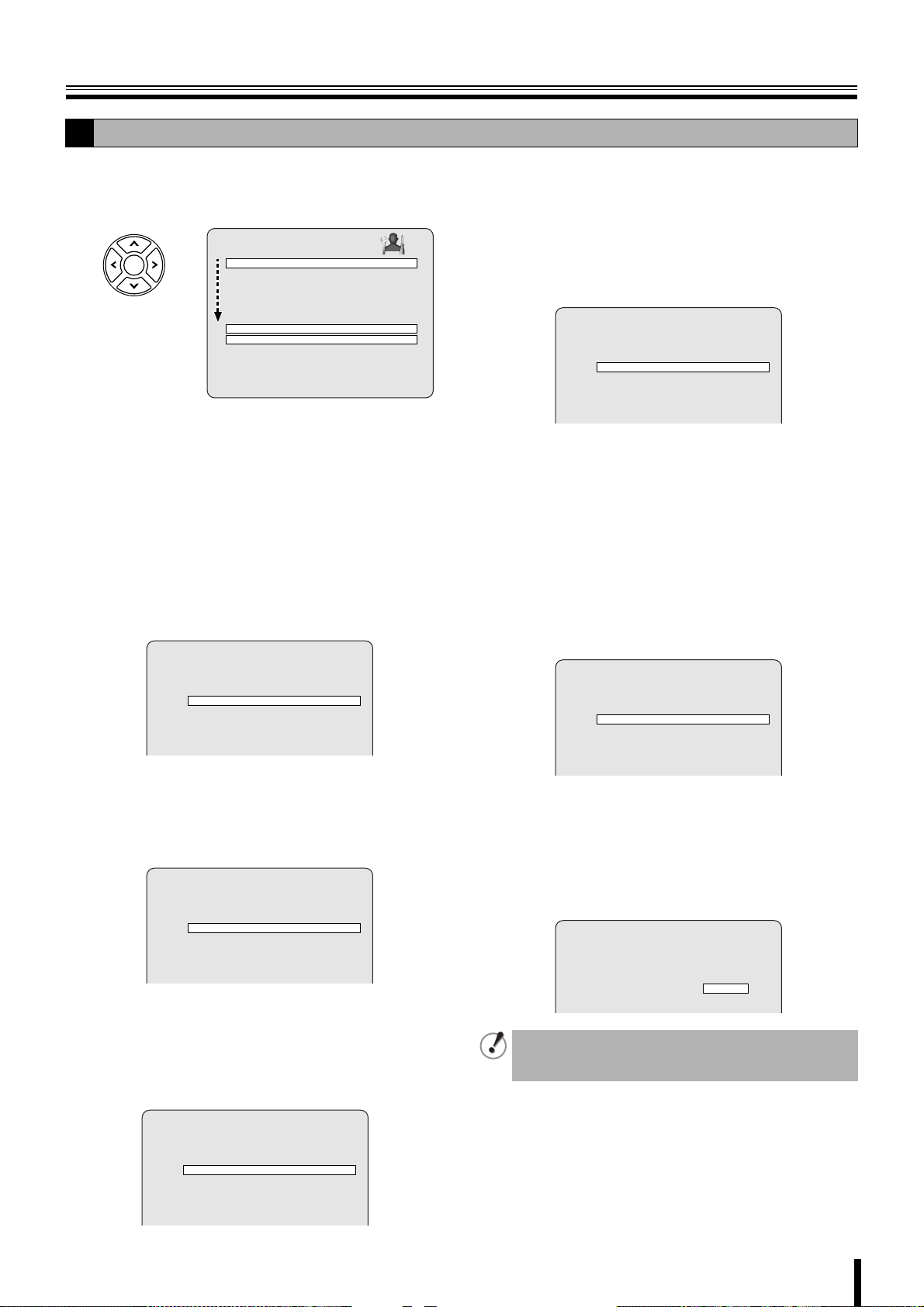
B
Press the control button (~) twice and select the
3
"SYSTEM", press the ENTER button.
The SYSTEM settings screen is displayed.
SYSTEM
DVR ID DVR
DESCRIPTION
LOAD DEFAULT
ADMIN PASSWORD
USER PASSWORD
NETWORK PASSWORD
DATE FORMAT YYYY/MM/DD
CLOCK SET
RS485 SET
PTZ CONTROL
LANGUAGE ENGLISH
REMOTE CONTROL ID 00
Select "DATE FORMAT" using the control button
4
({|) and select the date display format using the
control button (}~).
• YYYY/MM/DD
(Example: 2009/03/15)
• MM/DD/YYYY
• DD/MM/YYYY
Select "CLOCK SET" using the control button ({|)
5
and press the ENTER button.
•YYYY-MM-DD
(Example: 2009-03-15)
• MM-DD-YYYY
• DD-MM-YYYY
The CLOCK SET screen is displayed.
CLOCK SET
D.S.T./SUMMER TIMED.S.T./SUMMER TIME OFF
2009/03/15 10:20:30
Select "D.S.T./SUMMER TIME" using the control
6
button ({|), select the appropriate daytime saving
time zone using the control button (}~).
If choosing EU or OTHERS set the applicable
conditions.
CLOCK SET
1 Select the "GMT AREA" using the control button
({|).
2 Set the time difference with the standard time using
the control button (}~).
•OHTERS
If the time zone is neither USA nor EU, set the start
and end date of the daylight saving period.
CLOCK SET
D.S.T./SUMMER TIME OTHERS
BEGIN MAR 1st SUN 00H
END SEP 1st SUN 00H
2009/03/15 10:20:30
1 Select "BEGIN" using the control button ({|) and
press the ENTER button.
2 Select the item using the control button (}~),
select the setting value using the control button
({|).
3 Press the ENTER button once the daylight saving
start date is set.
4 Set the daylight saving end date using the same
procedure.
Select the display date and time using the control
7
button ({|).
CLOCK SET
D.S.T./SUMMER TIME OTHERS
BEGIN MAR 1st SUN 00H
END SEP 1st SUN 00H
2009/03/15 10:20:30
Select the item using the control button (}~), set
8
the date and time using the control button ({|)
and press the ENTER button.
The update time confirmation screen is displayed.
After you confirm the screen, select "CANCEL" or
"CONFIRM" using control button.
D.S.T./SUMMER TIME USA
2009/03/15 10:20:30
•OFF
Daylight saving is not set.
•USA
Applies the USA daylight saving time.
•EU
Applies the EU daylight saving time.
CLOCK SET
D.S.T./SUMMER TIME EU
GMT AREA +00:00
2009/03/15 10:20:30
CLOCK SET
CANCEL CONFIRM
The date and time displayed on the update time
confirmation screen takes daylight saving into
consideration.
10
Page 18
Pre-operation preparation
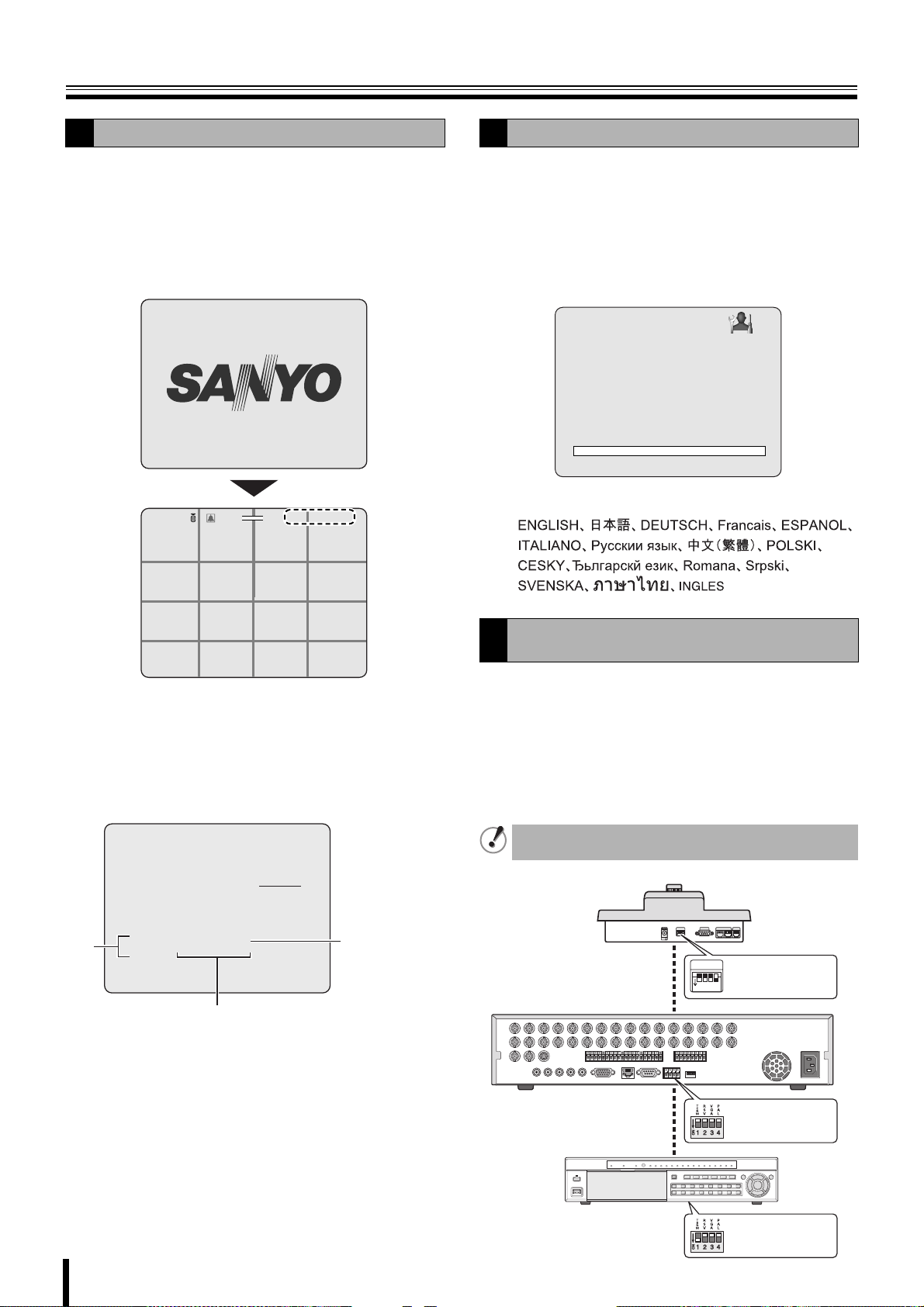
B
Select "CONFIRM" using the control button (}~)
9
and press the ENTER button.
The unit automatically restarts, the initializing screen is
displayed.
Once the initialization is complete and the live screen is
displayed, the displayed date and time are updated.
INTIALIZING...
Ver: XXXXXX.XX.XXXX(YYYYMMDD)
2%
2009/05/03 09:04:54
NO VIDEO
CH3
NO VIDEO
CH4
CH1
:A
NO VIDEO
C
CH2
Setting the language (LANGUAGE)
C
Follow steps 1 to 3 of the CLOCK SET procedure.
1
Select "LANGUAGE" using the control button ({|)
2
and select the display language using the control
button (}~).
Once a language has been selected the display
language changes.
SYSTEM
DVR ID DVR
DESCRIPTION
LOAD DEFAULT
ADMIN PASSWORD
USER PASSWORD
NETWORK PASSWORD
DATE FORMAT YYYY/MM/DD
CLOCK SET
RS485 SET
PTZ CONTROL
LANGUAGE ENGLISH
REMOTE CONTROL ID 00
Language selection:
CH5
CH9
CH13
NO VIDEO
CH6
NO VIDEO
CH10
NO VIDEO
CH14
NO VIDEO
CH7
NO VIDEO
CH11
NO VIDEO
CH15
NO VIDEO
CH8
NO VIDEO
CH12
NO VIDEO
CH16
NO VIDEO
NO VIDEO
NO VIDEO
b Correcting the set time
When a new time earlier than the previous recording time is
set, the recording data that will be erased, showed in range
A, is displayed on the clock update confirmation screen.
Confirm the time before selecting "CONFIRM" as any video
data recorded after the set time will be erased.
CLOCK SET
CANCEL CONFIRM
Caution: If you update to new T/D,
recorded data between new and rec-end T/D
will be deleted.
A
New T/D 2009/ 5/11 13:43:39
Rec-end T/D 2009/ 5/11 13:53:45
Previous recorded time
Set time
Setting the RS-485 termination switch (SANYO
D
SSP side)
If multiple devices are connected terminator settings are
necessary at both ends.
• When multiple devices are connected,
make the termination switch "ON" on the first and last
device you connected.
• When multiple devices are connected,
make the termination switch "OFF" except the first and last
devices that you connected.
If the termination switch is not set, the correct data will
not be delivered to each unit.
System controller
SW
Termination switch
ON
1
234
ON
11
Digital video recorder
RS485 Termination
switch (TERM) OFF
RS485 Termination
switch (TERM) ON
Page 19
Monitoring the camera videos
CD B
A
Single-screen display
A
Displays the video of the camera specified using the channel
selection button on single-screen.
Example: Displaying camera 2 on single-screen
Press "2" on the camera selection button.
The video of camera 2 is displayed on single-screen.
2%
CH2
2009/05/03 09:04:54
C
2
:A
Quad-screen display
B
Displays the 4 cameras video connected at once.
Press the QUAD button.
1
The videos of cameras 1 - 4 are displayed on
quad-screen.
2%
:A
CH1 C
CH3
Press the QUAD button again.
2
The videos of cameras 5-8 are displayed on
2009/05/03 09:04:54
CC
quad-screen.
Each time pressing the QUAD button, the video of the
camera changes as the quad-screen.
DSR-2116
CH2C
CH4
DSR-2108
0201
0403
1413
1615
0201
0403
0605
0807
1009
1211
0605
0807
12
Page 20
Monitoring the camera videos
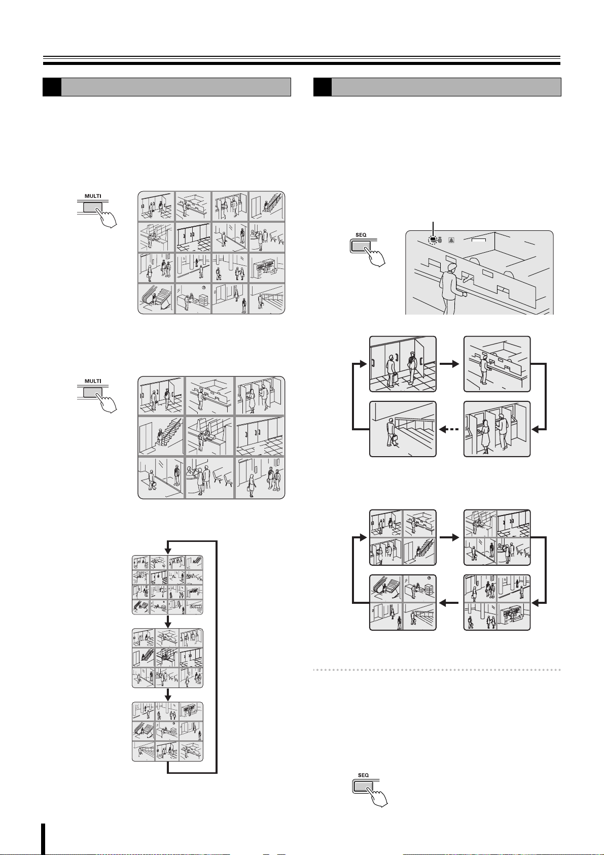
Multi-screen display
C
Displays the videos of 16 or 9 cameras simultaneously.
Press the MULTI button.
1
The videos of camera 1 - 16 are displayed on a multi-16
screen.
☞ In DSR-2108, the only available multi-screen is
multi-8 screen.
01 02
05 06
09 10 11 12
13 14 15
Press the MULTI button again.
2
The screen switches to a multi-9 screen, the videos of
camera 1 - 9 are displayed.
03 04
07 08
Camera sequencing
D
Automatically displays the channel in sequence on a single or
quad-screen.
Press the SEQ button while using the single or
1
quad-screen display.
The cameras automatically switch in sequence starting
with the channel of the camera being displayed. If there
is an audio input, the audio also switches in channel
sequence order.
Sequence display
2%
:A
16
2009/05/03 09:04:54
• When using single-screen display
01
04
07 08 09
05
0302
06
Pressing the button again switches the screen in turn
from a multi-9 screen (2 patterns) to a multi-16 screen.
01 02
05 06
09 10 11 12
13 14 15
01
01
04
04
07 08 09
07 08 09
10
13
16
03 04
07
05
05
14
01 02
08
12
16
0302
0302
06
06
1211
15
01
16
02
03
☞ In DSR-2108, single screens 1 to 8 are displayed
in sequence.
• When using quad-screen display
0201
0403
1413
1615
0605
0807
1009
1211
☞ In DSR-2108, the unit of 4 screens, 1 to 4 and 5 to
8, are displayed in sequence.
Memo: • The sequence interval from one camera video to
another can be set. (P31)
• Automatic camera sequencing is not available when
using multi-8, multi-9, or multi-16 screen.
Press the SEQ button once operations are
2
complete.
The sequence mode is cancelled.
13
Page 21
Operating the PTZ dome camera
Pan/Tilt, Zoom/Focus operations are possible from this unit when a coaxial superimposed type (COAX) camera is connected, or a
PTZ dome camera is connected using the RS-485 control terminal. Operation may not be possible depending on the connected
camera.
Connection
1
When connecting other than a coaxial superimposed type
(COAX) camera, connect the RS-485 control terminal of this
unit and that of the camera using a twisted pair cable.
Refer to "Connecting the RS-485 control terminal (P6)".
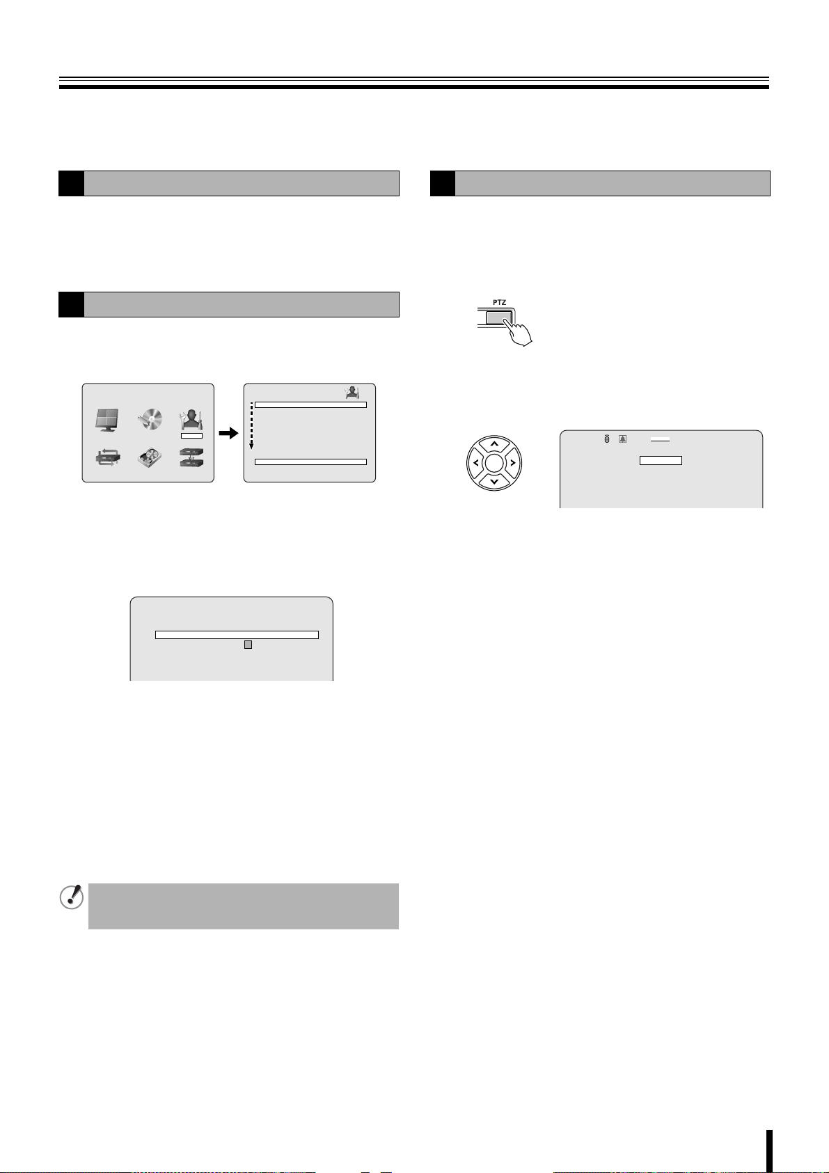
Settings
2
Press the MENU button (the MAIN MENU is
1
displayed) and select "SYSTEM" using the control
button (}~).
MAIN MENU
RECORDLIVE SYSTEM
HDD SETNETWORK SERVICE
DVR ID DVR
DESCRIPTION
LOAD DEFAULT
ADMIN PASSWORD
USER PASSWORD
NETWORK PASSWORD
DATE FORMAT YYYY/MM/DD
CLOCK SET
RS485 SET
PTZ CONTROL
LANGUAGE ENGLISH
REMOTE CONTROL ID 00
SYSTEM
• A password is requested when pressing the MENU
button. Enter the ADMIN PASSWORD. (P38)
Place the cursor on "PTZ CONTROL" and press the
2
ENTER button.
The PTZ screen is displayed.
PTZ
DATA SPEED 9600
CHANNEL 1
PROTOCOL --- ADDRESS 1
Point the cursor to "DATA SPEED" and set the
3
communication speed.
11
The set speed is applied to all channels except for
SANYO protocol.
Set the communication speed for the SANYO protocol
using RS485 SET. (P40)
Point the cursor to "CHANNEL", specify the
4
channel and set the "PROTOCOL" and "ADDRESS".
PROTOCOL: Selecting the type of protocol
ADDRESS: Camera ID (0 - 63)
When connecting multiple cameras to the RS-485 control
terminal, set the same protocol for all cameras except for
those cameras connected with SANYO protocol.
Operation
3
Select the number of the PTZ dome camera
1
connected using the camera selection button.
Press the PTZ button.
2
The control screen is displayed.
Controlling the camera
3
Control functions available differ according to the
camera model.
:A
IRIS/TOUR/SEQUENCE
2%
PAN/TILT
ZOOM/FOCUS
MENU
b Pan/Tilt operations
1 Select "PAN/TILT" using the control button ({|)
and press the ENTER button.
2 Adjust the tilt position using the control button ({|)
and adjust the pan position using the control button
(}~).
3 To perform automatic panning press the ENTER
button.
• The following message is displayed on the screen.
Up/Down key: Tilt Up/Down
Left/Right key: Pan Left/Right
Enter key: Auto Pan
b Zoom/Focus operations
1 Select "ZOOM/FOCUS" using the control button
({|) and press the ENTER button.
2 Adjust the zoom using the control button ({|) and
adjust the focus position using the control button
(}~).
3 To activate the auto focus press the ENTER button.
• The following message is displayed on the screen.
Up/Down key: Zoom In/Out
Left/Right key: Focus Near/Far
Enter key: Auto Focus
2009/05/03 09:04:54
Press the EXIT/STOP button once the settings are
5
complete.
14
Page 22

Operating the PTZ dome camera
3
b Iris/Tour/Sequence operations
1 Select "IRIS/TOUR/SEQUENCE" using the control
button ({|) and press the ENTER button.
2 To perform tour operations press the control button
({), to stop tour operations press the ENTER
button.
3 To perform sequence operations press the control
button (|), to stop sequence operations press the
ENTER button.
4 Adjust the aperture using the control button (}~).
• The following message is displayed on the screen.
Up/Down key: Tour ON/Sequence ON
Left/Right key: Iris Close/Open
Enter key: Tour/Sequence OFF
b Camera menu settings
1 Select "MENU" using the control button ({|) and
press the ENTER button.
2 Select a menu using the control button ({|) and
select a setting value using the control button (}~).
3 To switch to the next screen or validate a setting
value press the ENTER button.
• The following message is displayed on the screen.
Up/Down key: Cursor Up/Down
Left/Right key: Cursor Left/Right
Enter key: Enter
Press the EXIT/STOP button once operation are
4
complete.
If no "PROTOCOL" is set on the PTZ screen, the following
message is displayed on the screen.
"Please set up a camera type in setup menu."
15
Page 23
Recording
1 2
This unit allows the following recording modes.
Select the recording mode, recording resolution, frame rate
and video quality from "RECORD" under the MAIN MENU.
(P35)
The symbol on the right side of each recording mode (Ex: R)
is displayed while recording is in progress.
b Types of recording modes
A Real time recording (R) .................................. P16
Records manually videos being monitored.
B CONTINUOUS recording (C) ........................... P17
Records continuously when this unit is turned on.
C MOTION recording (M)..................................... P17
Records when set off by the motion sensor integrated in this
unit.
D ALARM recording (A) ...................................... P18
Records when set off by a sensor connected to the external
alarm terminal (ALARM IN) of this unit.
E SCHEDULE recording...................................... P19
Records according to the daily time slot set under the TIMER
SET screen of the recording settings.
• The initial screen requests a password. (P38)
• It is possible to cancel the password request.
See "Settings for no password" (P38)
Memo: Setting the OVERWRITE (P47)
ON: Continues recording by overwriting earlier
data even when the hard disk capacity is full.
OFF: Stops recording operations once the hard disk
capacity is full.
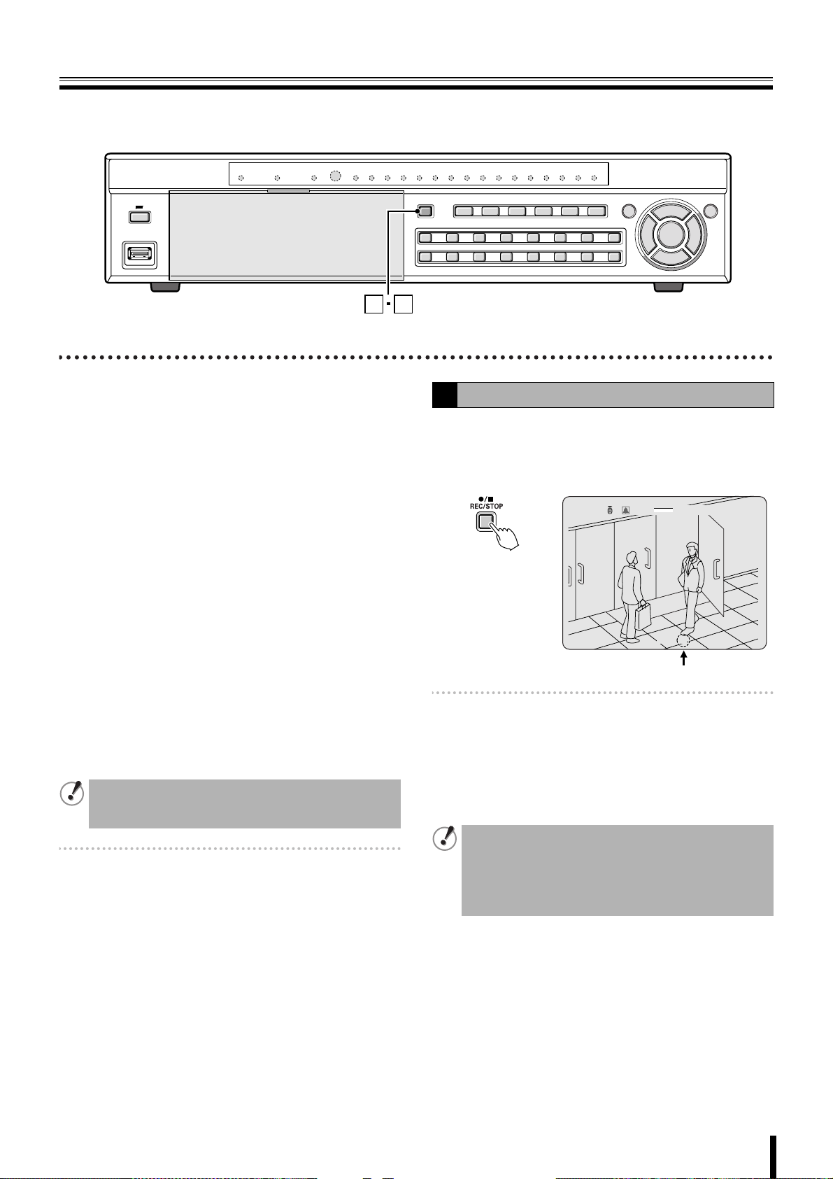
Real time recording
A
To manually start recording, press the REC/STOP
1
button while monitoring live video.
"R" is displayed on the recording display and recording
starts.
2%
CH1
2009/05/03 09:04:54
R
:A
Memo: When operated manually, the unit records according
to the settings for real time recording (REAL-TIME
REC SET). (P36)
Press the REC/STOP button once operations are
2
complete.
"R" disappears from the recording display and real time
recording is stopped.
• When recording rate is high, the audio may be difficult
to hear at the time of playback and playback time may
increase.
• Recording time varies depending on the screen being
recorded. Furthermore, recording rate may decrease
depending on the settings.
16
Page 24
Recording
CONTINUOUS recording
B
Recording starts automatically when this unit is
1
turned on.
"C" is displayed on the screen. The connected cameras
are simultaneously recorded.
The recording mode can be changed using
RECORDING under RECORD settings. Settings, such
as image quality, can also be set. (P35)
2%
C
CC
2009/05/03 09:04:54
CH2
CH4
:A
CH1 C
CH3
To stop recording, select "RECORDING" under
2
RECORD settings using the control button ({|) and
select "DISABLE" using the control button (}~).
“C” disappears.
Select "MOTION ZONE" using the control button
3
({|) and select the "PARTIAL ZONE" using the
control button (}~), press the ENTER button.
The motion setting screen is displayed.
• PARTIAL ZONE • FULL ZONE
If "FULL ZONE" is selected, the motion setting screen is
not displayed. Only set the level of sensitivity for MOTION
SENSITIVITY.
RECORD
RESOLUTION FULL
CHANNEL C
FRAME RATE 1 ips
QUALITY NORMAL
RECORDING MOTION
MOTION ZONE PARTIAL ZONE
MOTION SENSITIVITY 9
ALARM RECORDING -- -- -- - PRE RECORD OFF
POST EVENT RECORD 5 SECONDS
AUDIO OFF
TIMER SET
REAL-TIME REC SET
11
RECORD
RESOLUTION FULL
CHANNEL
FRAME RATE 1 ips
QUALITY NORMAL
RECORDING CONTINUOUS
MOTION ZONE FULL ZONE
MOTION SENSITIVITY 9
ALARM RECORDING -- -- -- - PRE RECORD OFF
POST EVENT RECORD 5 SECONDS
AUDIO OFF
TIMER SET
REAL-TIME REC SET
MOTION recording
C
11
A motion sensor can be set for each channel.
Adjusting the following settings using the control
1
button ({|}~).
• RESOLUTION
• CHANNEL
Select "RECORDING" using the control button
2
({|) and select "MOTION" using the control
• FRAME RATE
•QUALITY
button (}~).
Detection
frame
Select the sensor detection position using the
4
control button ({|}~) and press the ENTER
button.
The frame set for the sensor detection is grainy.
Select a sensor detection position by repeating the
operation.
Once the setting of the event searched is complete,
press the EXIT/STOP button to return to the RECORD
screen.
Select "MOTION SENSITIVITY" using the control
5
button ({|) and select the level of sensitivity
using the control button (}~).
Selections: 1-9 (Low sensitivity)
Select "PRE RECORD" using the control button
6
({|) and select the pre recording as necessary
using the control button (}~).
Select "POST EVENT RECORD" using the control
7
button ({|) and select the recording time as
necessary using the control button (}~).
Selections: 2 - 30 SECONDS, 1 - 5 MINUTES,
10 MINUTES, 15 MINUTES
17
Press the EXIT/STOP button once operations are
8
complete.
Press the EXIT/STOP button repeatedly to return to the
live video.
Page 25
Recording
ALARM recording
D
An external sensor can be connected to each channel.
Connecting an external switch to an external alarm
1
input terminal.
Camera
(Sold separately)
POWERMODEAUTOMENU
Monitor
(Sold
separately)
Set the following items using the control button
2
({|}~).
• RESOLUTION
• CHANNEL
• FRAME RATE
•QUALITY
Select "PRE RECORD" using the control button
5
({|) and select the pre recording as necessary
using the control button (}~).
Select "POST EVENT RECORD" using the control
6
button ({|) and select the recording time as
necessary using the control button (}~).
Selections: 2 to 30 SECONDS, 1 to 5 MINUTES,
10 MINUTES, 15 MINUTES
Press the EXIT/STOP button once operations are
7
complete.
Press the EXIT/STOP button repeatedly to return to the
live screen.
Memo: Set the alarm input conditions using "ALARM-SET"
in LIVE settings. (P32)
Select "RECORDING" using the control button
3
({|) and select "ALARM" using the control button
(}~).
RECORD
RESOLUTION FULL
CHANNEL C
FRAME RATE 1 ips
QUALITY NORMAL
RECORDING ALARM
MOTION ZONE FULL ZONE
MOTION SENSITIVITY 9
ALARM RECORDING -- -- -- - PRE RECORD OFF
POST EVENT RECORD 5 SECONDS
AUDIO OFF
TIMER SET
REAL-TIME REC SET
Select "ALARM RECORDING" using the control
4
button ({|) and set the alarm input terminal
number.
An ALARM recording is activated if there is an input in
the specified external alarm input terminal.
Select a setting location (4 locations) using the control
button (}~), and select an input terminal number
using the control button ({|).
11
18
Page 26
Recording
SCHEDULE recording
E
Adjusting the following settings using the control
1
button ({|}~).
• RESOLUTION
• CHANNEL
Select "RECORDING" using the control button
2
({|) and select "SCHEDULE" using the control
• FRAME RATE
•QUALITY
button (}~).
The following settings are necessary when performing
sensor detection.
• MOTION ZONE
• MOTION SENSITIVITY
• PRE RECORD
• POST EVENT RECORD
Select "SCHEDULE" using the control button ({|)
3
and press the ENTER button.
When the channel 1 is selected, "TIMER SET-CH1"
screen is displayed.
RECORD
RESOLUTION FULL
CHANNEL
FRAME RATE 1 ips
QUALITY NORMAL
RECORDING SCHEDULE
MOTION ZONE FULL ZONE
MOTION SENSITIVITY 9
ALARM RECORDING -- -- -- - PRE RECORD OFF
POST EVENT RECORD 5 SECONDS
AUDIO OFF
TIMER SET
REAL-TIME REC SET
Select "ALL" or each day using the control button
4
({|) and set the recording mode using the ENTER
11
button.
Repeat the procedure to set a different recording mode.
-: DISABLE (Does not record)
C: CONTINUOUS recording
M: MOTION recording
A: ALARM recording
Input example:
TIMER SET - CH1
COPY FROM CH1
COPY TO CH1
0 3 6 9 12 15 18 21
ALL
SUN - - - - - - - - - - - - - - - - - - - - -
CAM
MON - - - - - - - - - - - - - - - - - - - - -
ACM
TUE - - - - - - - - - - - - - - - - - - - - -
AMM
WED - - - - - - - - - - - - - - - - - - - - - - - -
THU - - - - - - - - - - - - - - - - - - - - - - - -
FRI - - - - - - - - - - - - - - - - - - - - - - - -
SAT - - - - - - - - - - - - - - - - - - - - - - - -
• Selecting an identical setting for every day
(Example: CONTINUOUS):
Move the cursor to "ALL", the display turns red.
Repeatedly pressing the ENTER button sets the
same setting for every day.
TIMER SET - CH1
COPY FROM CH1
COPY TO CH1
0 3 6 9 12 15 18 21
ALL
SUN C C C C C C C C C C C C C C C C C C C C C C C C
MON C C C C C C C C C C C C C C C C C C C C C C C C
TUE C C C C C C C C C C C C C C C C C C C C C C C C
WED C C C C C C C C C C C C C C C C C C C C C C C C
THU C C C C C C C C C C C C C C C C C C C C C C C C
FRI C C C C C C C C C C C C C C C C C C C C C C C C
SAT C C C C C C C C C C C C C C C C C C C C C C C C
• Selecting the same setting for a whole day
(Example: MOTION):
Move the cursor to the day, the display turns red.
Repeatedly pressing the ENTER button sets the
same setting for the whole day.
TIMER SET - CH1
COPY FROM CH1
COPY TO CH1
0 3 6 9 12 15 18 21
ALL
SUN - - - - - - - - - - - - - - - - - - - - - - - -
M M M M M M M M M M M M M M M M M M M M M M M M
MON
TUE - - - - - - - - - - - - - - - - - - - - - - - -
WED - - - - - - - - - - - - - - - - - - - - - - - -
THU - - - - - - - - - - - - - - - - - - - - - - - -
FRI - - - - - - - - - - - - - - - - - - - - - - - -
SAT - - - - - - - - - - - - - - - - - - - - - - - -
• Selecting the same setting for a specified time
only every day (Example: MOTION):
Move the cursor to "ALL" and move the cursor to the
specified time using the control button (~), the
longitudinal bar changes to = (red). Press the
ENTER button repeatedly to set the same setting
(M).
TIMER SET - CH1
COPY FROM CH1
COPY TO CH1
0 3 6 9 12 15 18 21
=
ALL
M
SUN - - - - - - - - - - - - - - - - - - - - - - -
M
MON - - - - - - - - - - - - - - - - - - - - - - -
M
TUE - - - - - - - - - - - - - - - - - - - - - - -
M
WED - - - - - - - - - - - - - - - - - - - - - - -
M
THU - - - - - - - - - - - - - - - - - - - - - - -
M
FRI - - - - - - - - - - - - - - - - - - - - - - -
M
SAT - - - - - - - - - - - - - - - - - - - - - - -
Press the EXIT/STOP button once operations are
5
complete.
Press the EXIT/STOP button repeatedly to return to the
live screen.
19
Page 27
Recording
E
b Copying a set recording schedule to other channels
Example 1
Set the channel 1 schedule and press the EXIT/
1
STOP button.
Copying the channel 1 schedule to channel
3 (COPY FROM)
The RECORD screen is displayed again.
TIMER SET - CH1
COPY FROM CH1
COPY TO CH1
0 3 6 9 12 15 18 21
ALL
SUN - - - - - - - - - - - - - - -
CMA C MA CMA
MON - - - - - - - - - - - - - -
ACMA CMA CMA
ACMA CMA CMA
TUE - - - - - - - - - - - - - -
AMCMA CMACMA
WED - - - - - - - - - - - - -
AMCMA CMACM
THU - - - - - - - - - - - - - -
FRI - - - - - - - - - - - - -
SAT - - - - - - - - - - - - - -
Select "CHANNEL" using the control button ({|)
2
and select CH3 using the control button (}~).
Select "TIMER SET" using the control button ({|)
3
and press the ENTER button.
AMCMA CMACMC
AMCMA CMACC
The "TIMER SET-CH3" screen is displayed.
RECORD
RESOLUTION FULL
CHANNEL
FRAME RATE 1 ips
QUALITY NORMAL
RECORDING CONTINUOUS
MOTION ZONE FULL ZONE
MOTION SENSITIVITY 9
ALARM RECORDING -- -- -- - PRE RECORD OFF
POST EVENT RECORD 5 SECONDS
AUDIO OFF
TIMER SET
REAL-TIME REC SET
TIMER SET - CH3
COPY FROM CH1
COPY TO CH1
0 3 6 9 12 15 18 21
ALL
SUN - - - - - - - - - - - - - - -
CMA C MA CMA
33
Example 2
Set the channel 1 schedule and select "COPY TO"
1
using the control button ({|), select "CH2" using
Copying the channel 1 schedule to channel
2 (COPY TO)
the control button (}~) and press the ENTER
button.
The CH1 schedule is copied to CH2.
TIMER SET - CH1
COPY FROM CH1
COPY TO CH1
0 3 6 9 12 15 18 21
ALL
SUN - - - - - - - - - - - - - - - -
CMA CMC AC
MON - - - - - - - - - - - - - - - -
CMACMC AC
TUE - - - - - - - - - - - - - - - -
CMA CMC AC
WED - - - - - - - - - - - - - - - -
CMACMC AC
THU - - - - - - - - - - - - - - - -
CMA CMC AC
FRI - - - - - - - - - - - - - - - -
CMACMC AC
SAT - - - - - - - - - - - - - - - -
CMA CMC AC
Press the EXIT/STOP button.
2
The RECORD screen is displayed again.
Select "CHANNEL" using the control button ({|)
3
and select "CH2" using the control button (}~).
Select "TIMER SET" using the control button ({|)
4
and press the ENTER button.
The "TIMER SET-CH2" screen is displayed. The CH1
schedule is copied to CH2.
TIMER SET - CH2
COPY FROM CH1
COPY TO CH1
0 3 6 9 12 15 18 21
ALL
SUN - - - - - - - - - - - - - - - -
CMA CMC AC
MON - - - - - - - - - - - - - - - -
CMACMC AC
TUE - - - - - - - - - - - - - - - -
CMA CMC AC
WED - - - - - - - - - - - - - - - -
CMACMC AC
THU - - - - - - - - - - - - - - - -
CMA CMC AC
FRI - - - - - - - - - - - - - - - -
CMACMC AC
SAT - - - - - - - - - - - - - - - -
CMA CMC AC
Select "COPY FROM" using the control button
4
({|) and select "CH1" using the control button
(}~), press the ENTER button.
The CH1 recording schedule is copied to CH3.
Press the EXIT/STOP button once operations are
5
complete.
Press the EXIT/STOP button repeatedly to return to the
live screen.
20
Page 28

Playing back recorded videos
The following recorded videos searching methods are available.
b EVENT SEARCH (P22)
Search through a recorded video list by setting the date on the calendar
display, the camera channel and specify the type of recording.
SEARCH
EVENT
5 6 7 8 9 10 11
12 13 14 15 16 17 18
19 20 21 22 23 24 25
26 27 28 29 30
2 3 4 51 6 7 8
10 11 12 13914 15 16
M A R
C
SEARCH
TIMELINE
5 6 7 8 9 10 11
12 13 14 15 16 17 18
19 20 21 22 23 24 25
26 27 28 29 30
SEARCH
2009/04/14 17:17:00
2%
:A
2009/05/03 09:04:54
SEARCH
EVENT SEARCH
TIMELINE SEARCH
T/D SEARCH
GO FIRST
GO LAST
LOG
BOOKMARK
b BOOKMARK (P25)
Searches through the bookmarked still images
or moving videos.
BOOKMARK
2009-04
1 2 3 4
5 6 7 8 9 10 11
12 13 14 15 16 17 18
19 20 21 22 23 24 25
26 27 28 29 30
2009-04 1 2 3 4
CHANNEL
TYPE
b TIMELINE SEARCH (P23)
Searching for an event by setting the date, time on the timeline.
2009-04 1 2 3 4
b T/D SEARCH (P24)
Searching for an event by setting the date, time numerically.
SEARCH
2009/04/12 10:00:00
048121620
HOUR
MINUTES HDD A V A
CH 1
CH 2
CH 3
CH 4
CH 5
CH 6
CH 7
CH 8
CH 9
CH10
CH11
CH12
CH13
CH14
CH15
CH16
ALL
AUDIO
b The function of each button during
playback.
The fast forward speed changes each
time it is pressed, the symbol is displayed
e
f
SKIP Jumps the video 1 minute forward
REPLAY Jumps the video 1 minute backward
c/h
EXIT/STOP
b
on the bottom right of the screen.
c
(Standard) → 2e(X2) → 4e→ 8e
(Maximum x4 when playing back in
multi-screen format)
The fast rewind speed changes each
time it is pressed, the symbol is displayed
on the bottom right of the screen.
d
(Standard) → 2f(X2) → 4f→ 8f
(Maximum x4 when playing back in
multi-screen format)
Pause (Still image display)
Press again to restart playback.
Stops a playback in progress
b GO FIRST (P24)
Searching the first (oldest) recording data.
b GO LAST (P24)
Searching the last (newest) recording data.
b LOG (P24)
Viewing the operation / activities (LOG) of this unit on a specified date.
LOG
2009-04
1 2 3 4
5 6 7 8 9 10 11
12 13 14 15 16 17 18
19 20 21 22 23 24 25
26 27 28 29 30
Playback may be slow when the unit is establishing a network
connection, or because of the recording conditions.
LIST
2009/04/14 (1/1)
[03:28:37] System Start
[08:02:58] System Start
[08:04:20] Manual Record Start
[08:04:35] Manual Record Stop
[08:04:50] Manual Record Start
[08:05:03] Manual Record Stop
[08:06:34] Enter Setup
[17:03:36] System Start
[17:05:04] System Start
[17:08:07] Manual Record Start
[17:08:52] Manual Record Stop
21
Page 29

Playing back recorded videos
EVENT SEARCH
A
1 2 6 7
Press the SEARCH button.
1
The menu screen is displayed.
SEARCH
EVENT SEARCH
TIMELINE SEARCH
T/D SEARCH
GO FIRST
GO LAST
LOG
BOOKMARK
Select "EVENT SEARCH" using the control button
2
({|) and press the ENTER button.
The SEARCH screen is displayed.
Select the date you want to search using the
3
control button ({|}~) and press the ENTER
button.
The cursor moves to CHANNEL.
• If recordings are available, the date is displayed in
red.
: Indicates that there are recordings in the
previous month.
: Indicates that there are recordings in the next
month.
Move the cursor to the day of the first recording in
the month displayed by the calendar, pressing the }
button displays the previous month of the calendar.
Move the cursor to the day of the last recording in
the month displayed by the calendar, pressing the ~
button displays the next months of the calendar.
Select the type of recording (M/A/R/C) to be
5
searched using the control button (}~) and press
the ENTER button.
The selected type of recording is displayed in red.
If the 4 letters are displayed in red, all the type of
recordings have been selected.
M: Recording activated by motion detection
(MOTION)
A: Recording activated by an external alarm input
(ALARM)
R: Real time recording
C: Continuous recording (CONTINUOUS)
Example:
Searching recordings activated by the motion detection
(M) of the channel 2 of the camera
CHANNEL
TYPE
2 3 4 51 6 7 8
10 11 12 13914 15 16
M A R
C
The list screen is displayed.
Select the videos to be played back using the
6
control button ({|), and press the ENTER button.
Playback starts.
If the list continues on several pages, use the control
button (}~) to change pages.
LIST
2009/04/12 (1/1)
<hda> [08:04:20] CH2:MOTION
<hda> [08:04:50] CH2:MOTION
<hda> [17:08:07] CH2:MOTION
SEARCH
2009-04 1 2 3 4
CHANNEL
TYPE
Select a channel with the control button (}~) and
4
press the ENTER button.
EVENT
5 6 7 8 9 10 11
12 13 14 15 16 17 18
19 20 21 22 23 24 25
26 27 28 29 30
2 3 4 51 6 7 8
10 11 12 13914 15 16
M A R
C
The cursor moves to TYPE.
• To select all the channels, select .
CH2
Playback in progress display
Press the EXIT/STOP button once operations are
7
complete.
Press the EXIT/STOP button repeatedly to return to the
live screen.
22
Page 30

Playing back recorded videos
TIMELINE SEARCH
B
Press the SEARCH button.
1
The search menu screen is displayed.
Select "TIMELINE SEARCH" using the control
2
button ({|) and press the ENTER button.
The SEARCH screen is displayed.
• If recordings are available, the date is displayed in
red.
: Indicates that there are recordings in the
previous month.
: Indicates that there are recordings in the next
month.
Move the cursor to the day of the first recording in
the month displayed by the calendar, pressing the }
button displays the previous month of the calendar.
Move the cursor to the day of the last recording in
the month displayed by the calendar, pressing the ~
button displays the next months of the calendar.
SEARCH
2009-04 1 2 3 4
Select the date to be played back using the control
3
button ({|}~) and press the ENTER button.
TIMELINE
5 6 7 8 9 10 11
12 13 14 15 16 17 18
19 20 21 22 23 24 25
26 27 28 29 30
The timeline screen is displayed.
The recording information of the selected date is
displayed in the timeline.
1 HOUR scale
Displays 24 hours (1 hour x 24 marks).
Periods of recording are displayed using a blue
timeline.
Move the yellow cursor left and right to display the
MINUTES scale for the desired hour.
2 MINUTES scale
Displays 1 hour (5 minutes x 12 marks).
The recording information of each channel for the
period specified using the HOUR scale is displayed
on the blue timeline.
Move the yellow cursor of the HOUR scale to the
4
specified period using the control button ({|) and
press the ENTER button.
The HOUR scale cursor turns light blue and the
timeline of the head channel of the MINUTES scale
turns yellow.
Select the channel to be played using the control
5
button ({|).
The timeline of the selected channel is displayed in
yellow.
SEARCH
2009/04/12 11:00:00
0 4 8 12 16 20
HOUR
MINUTES HDD A V A
CH 1
CH 2
CH 3
CH 4
CH 5
CH 6
CH 7
CH 8
CH 9
CH10
CH11
CH12
CH13
CH14
CH15
CH16
ALL
AUDIO
Memo: To play the video of all the channels simultaneously
on a multi-16 screen select "ALL".
Move the vertical line (MINUTES scale) of the scale
6
to the playback start point using the control
buttons (}~) and press the ENTER button.
The recording starts playing from the specified point.
SEARCH
2009/04/12 11:25:00
0 4 8 12 16 20
HOUR
MINUTES HDD A V A
CH 1
CH 2
CH 3
CH 4
CH 5
CH 6
CH 7
CH 8
CH 9
CH10
CH11
CH12
CH13
CH14
CH15
CH16
ALL
AUDIO
SEARCH
2009/04/12 10:00:00
0 4 8 12 16 20
1
2
HOUR
MINUTES HDD A V A
CH 1
CH 2
CH 3
CH 4
CH 5
CH 6
CH 7
CH 8
CH 9
CH10
CH11
CH12
CH13
CH14
CH15
CH16
ALL
AUDIO
Memo: • Initially, the timeline of ALL is displayed in light blue.
• If there is an audio track, a timeline appears next to
the bottom line "AUDIO".
23
Memo: The vertical line (MINUTES scale) moves one minute
at the time.
Press the EXIT/STOP button once operations are
7
complete.
Press the EXIT/STOP button repeatedly to return to the
live screen.
Page 31

Playing back recorded videos
T/D SEARCH
C
Press the SEARCH button.
1
The search menu screen is displayed.
Select "T/D SEARCH" using the control button
2
({|) and press the ENTER button.
The SEARCH screen is displayed.
Select the date and time to be played back using
3
the control button (}~) and input a value using the
control button ({|).
SEARCH
2009/04/14 17:17:00
Press the ENTER button.
4
Playback starts.
• When there is no video recorded on the specified
date, playback may not start.
Press the EXIT/STOP button once operations are
5
complete.
Press the EXIT/STOP button repeatedly to return to the
live screen.
GO FIRST
D
Press the SEARCH button.
1
The menu screen is displayed.
LOG
F
Press the SEARCH button.
1
The menu screen is displayed.
Select "LOG" using the control button ({|) and
2
press the ENTER button.
The LOG screen is displayed.
• If recordings are available, the date is displayed in
red.
: Indicates that there are recordings in the
previous month.
: Indicates that there are recordings in the next
month.
Moving the cursor to the day of the first recording in
the month displayed by the calendar and pressing
the } button displays the previous month of the
calendar. Moving the cursor to the day of the last
recording in the month displayed by the calendar
and pressing the ~ button displays the next months
of the calendar.
LOG
2009-04
1 2 3 4
5 6 7 8 9 10 11
12 13 14 15 16 17 18
19 20 21 22 23 24 25
26 27 28 29 30
Select the date to be displayed using the control
3
button ({|}~) and press the ENTER button.
The LIST screen is displayed.
• If several lists are available, the previous or next
LIST can be viewed using the control button (}~).
Select "GO FIRST" using the control button ({|)
2
and press the ENTER button.
The first recording is played back.
Press the EXIT/STOP button once operations are
3
complete.
Press the EXIT/STOP button repeatedly to return to the
live screen.
GO LAST
E
Press the SEARCH button.
1
The menu screen is displayed.
Select "GO LAST" using the control button ({|)
2
and press the ENTER button.
The last recording is played back.
Press the EXIT/STOP button once operations are
3
complete.
Press the EXIT/STOP button repeatedly to return to the
live screen.
LIST
2009/04/14 (1/1)
[03:28:37] System Start
[08:02:58] System Start
[08:04:20] Manual Record Start
[08:04:35] Manual Record Stop
[08:04:50] Manual Record Start
[08:05:03] Manual Record Stop
[08:06:34] Enter Setup
[17:03:36] System Start
[17:05:04] System Start
[17:08:07] Manual Record Start
[17:08:52] Manual Record Stop
Press the EXIT/STOP button once operations are
4
complete.
Press the EXIT/STOP button repeatedly to return to the
live screen.
24
Page 32

Playing back recorded videos
BOOKMARK
G
Perform the mark operation of the desired live video.
The marked event can be selected and displayed from the list
(date). (P26, 27)
Press the SEARCH button.
1
The menu is displayed.
SEARCH
EVENT SEARCH
TIMELINE SEARCH
T/D SEARCH
GO FIRST
GO LAST
LOG
BOOKMARK
Select "BOOKMARK" using the control button
2
({|) and press the ENTER button.
The BOOKMARK screen is displayed.
• If bookmarks are available, the date is displayed in
red.
: Indicates that there are bookmarks in the
previous month.
: Indicates that there are bookmarks in the next
month.
Moving the cursor to the day of the first bookmark in
the month displayed by the calendar and pressing
the } button displays the previous month of the
calendar. Moving the cursor to the day of the last
bookmark in the month displayed by the calendar
and pressing the ~ button displays the next months
of the calendar.
Select an event which date is displayed in red using
3
the control button ({|}~) and press the ENTER
button.
LIST is displayed.
BOOKMARK
2009-04
1 2 3 4
5 6 7 8 9 10 11
12 13 14 15 16 17 18
19 20 21 22 23 24 25
26 27 28 29 30
2009/04/14 (1/1)
[2009/04/14 17:20:48] LIVE JPEG
[2009/04/14 17:21:04] LIVE JPEG
[2009/04/14 17:23:02] CH1 AVI 2SEC
Select the date to be played back from the list using
4
the control button ({|) and press the ENTER
LIST
button.
The still image is displayed.
25
Page 33

Copying recorded video to recording media
Necessary video can be selected and copied to USB memory or to a DVD-R, CD-R/RW.
Inserting recording media
A
Insert the recording media (USB memory) in advance before
you perform copy operation.
12
1 To copy onto a USB memory
Connect a USB memory to the USB terminal on the front
panel.
2 To copy onto a DVD-R, CD-R/RW
To open and close the insert tray, open the panel of the
disk drive and press the button.
• DVD-R, CD-R:
Use new discs.
• CD-RW:
If there is data previously written on the disc,
use Windows Explorer to erase the data.
Copying live videos
B
Press the MARK/COPY button at the scene to be
1
copied while monitoring live videos.
The copy screen is displayed after the "BOOKMARK
OK" message.
2%
:A
Do you want to backup?
NO YES
Select media to backup.
USB stick
CD-RW
In response to the confirmation message (Do you
2
want to backup?) select "YES" using the control
button (}~).
Memo: Regardless of whether "YES/NO" is selected, images
are marked and recorded from the point when the
MARK/COPY button is pressed. Search/display of
marked still image can be performed using
BOOKMARK in the search menu. (P25)
Select the recording media (USB stick or CD-RW)
3
onto which the video should be copied using the
control button ({|) and press the ENTER button.
The message "SAVING..." is displayed and copying
starts.
When copying is complete the message "SAVE
SUCCESS" is displayed.
2009/05/03 09:04:54
Memo: If the specified recording media has not been
inserted, an error message is displayed depending
on the type or state of the inserted media.
Press the EXIT/STOP button once operations are
4
complete.
Press the EXIT/STOP button repeatedly to return to the
live screen.
26
Page 34

Copying recorded video to recording media
Copying a playback video
C
The image to be copied can be selected on still and moving
images.
While playing back the recorded video press the
1
MARK/COPY button at the scene to be copied.
The video is paused and the BOOKMARK screen is
displayed.
2009/04/14 17:25:37
BOOKMARK
STILL VIDEO
CH1
Select the copy mode (STILL or VIDEO) using the
2
control button (}~) and press the ENTER button.
•STILL:
Copies still images.
Pressing the ENTER button displays the copy
screen. (go to step 5)
•VIDEO:
Copies moving images.
Pressing the ENTER button displays the DURATION
screen. (go to step 3)
DURATION 00MIN(TO 60)
2009/04/14 17:25:37 - 2009/04/14 17:25:37
CH1
Select the channel to be copied using the channel
3
selection button (1 - 16).
☞ In DSR-2108, channel selection buttons are 1 to 8.
The colour of the corresponding channel indicator
changes alternatively each time a channel selection
button is pressed.
•Yellow: Copy enabled
• White: Copy disabled
Memo: The images of channels indicated in yellow are
sequentially copied to the recording media.
Specify the hour (minutes) to be saved using the
4
control buttons ({|}~) and press the ENTER
button.
The copy screen is displayed.
Memo: Select a digit using the control button (}~) and
select a value using the control button ({|). Up to a
maximum of 60 minutes can be selected when using
minutes as a unit.
In response to the confirmation message (Do you
5
want to backup?) select "YES" using the control
button (}~).
2%
:A
Do you want to backup?
NO YES
Select media to backup.
USB stick
CD-RW
Memo: If "YES" is selected, the image at the point where the
MARK/COPY button is pressed is marked and
recorded. Search/display of marked still image can
be performed using BOOKMARK in the search
menu. (P25)
Select the recording media (USB stick or CD-RW)
6
onto which the video should be copied using the
control button ({|) and press the ENTER button.
The message "SAVING..." is displayed and copying
starts.
When copying is complete the message "SAVE
SUCCESS" is displayed.
Memo: If the specified recording media has not been
inserted, or there is a problem with the media type or
state of the inserted media, an error message is
displayed.
Press the EXIT/STOP button once operations are
7
complete.
Press the EXIT/STOP button repeatedly to return to the
live screen.
Playing back copied videos
D
Still images are copied in a JPG format and video images are
recorded in AVI format. Ensure that an image display
software compatible with the JPG format is used to playback
still images and a video imaging software compatible with the
AVI format is used to playback video images.
Folder structure of copied videos
YYYYMMDD hhmmsscc.avi (Moving video file)
Year
Memo: If the video cannot be played with standard video
Day
Month
software, install FFDShow (Codec) from the supplied
CD-ROM.
• To start the installer insert the CD-ROM in the drive
of the PC and double-click on the
"ffdshowyyyymmdd.exe" file.
• Follow the setup wizard and install using the initial
settings for codec, filters, etc.
hhmmsscc.smi
hhmmsscc.avi
hhmmsscc.smi
Hour
Second
Minute
(Ancillary moving video
information file)
Channel
2009/04/14 09:04:54
27
Page 35

Setting the security lock
Setting a security lock locks all the operation buttons of this
unit.
b Setting a security lock
Press the EXIT/STOP button for approximately
1
5 seconds.
The password entering screen is displayed.
2%
:A
PASSWORD
- - - -
Enter the "ADMIN PASSWORD" using the channel
2
selection buttons.
The factory default password is "1111".
2009/05/03 09:04:54
CH1
Press the ENTER button.
3
The security lock is set and the blue security lock icon is
displayed.
2%
:A
b Canceling the security lock
Press the EXIT/STOP button for approximately
1
5 seconds.
The password entering screen is displayed.
Enter the "ADMIN PASSWORD" using the channel
2
selection buttons.
Press the ENTER button.
3
The security lock is cancelled and the blue security lock
icon disappears.
2009/05/03 09:04:54
28
Page 36

Configuration and function of the Menu settings
b LIVE settings (P31)
To perform adjustments related to live
videos monitoring such as sequencing
settings and each camera video
adjustments.
LIVE
OSD ON
SEQUENCE ON
SEQUENCE-DWELL TIME 2 SECONDS
EVENT BEEP OFF
OSD CONTRAST 90%
CHANNEL CH1
DISPLAY ON
BRIGHTNESS 50%
CONTRAST 50%
HUE 50%
SATURATION 50%
ALARM-SET
MON2-OUT
2%
:A
:A
2%
11
2007/05/03 09:04:54
2009/05/03 09:04:54
MAIN MENU
b RECORD settings (P35)
To perform adjustments related to
recordings such as resolution, the
recording mode for each channel,
video quality, motion and alarm
settings.
RECORD
RESOLUTION FULL
CHANNEL
FRAME RATE 1 ips
QUALITY NORMAL
RECORDING CONTINUOUS
MOTION ZONE FULL ZONE
MOTION SENSITIVITY 9
ALARM RECORDING -- -- -- - PRE RECORD OFF
POST EVENT RECORD 5 SECONDS
AUDIO OFF
TIMER SET
REAL-TIME REC SET
MAIN MENU
11
b SYSTEM settings (P37)
To perform settings carried out by the
manager, such as setting initialization
and password, date and time,
language and PTZ CONTROL settings.
SYSTEM
DVR ID DVR
DESCRIPTION
LOAD DEFAULT
ADMIN PASSWORD
USER PASSWORD
NETWORK PASSWORD
DATE FORMAT MM/DD/YYYY
CLOCK SET
RS485 SET
PTZ CONTROL
LANGUAGE ENGLISH
REMOTE CONTROL ID 00
PASSWORD
PASSWORD
- - - -
- - - -
CH1 C
CH1
(See P9)
b NETWORK settings (P42)
To perform remote operations by
network and PC connection.
NETWORK
PORT 5445
CLIENT ACCESS ON
BANDWIDTH SAVING ON
NETWORK TYPE LAN
IP 0.0.0.0
SUBNET MASK 0.0.0.0
GATEWAY 0.0.0.0
DNS 0.0.0.0
DDNS OFF
SEND E-MAIL OFF
NTP SET OFF
RECORDLIVE SYSTEM
HDD SETNETWORK SERVICE
b HDD SET settings (P47)
Settings related to the hard disk such
as overwriting settings and
initialization.
HDD SET
OVERWRITE ON
FORAMT
AUTO DELETE OFF
AUTO DELETE DAYS 30 DAYS
b SERVICE settings (P49)
To perform such operations as saving
the settings to the USB memory.
SERVICE
SAVE SETUP TO A USB
LOAD SETUP FROM A USB
DISK INFO
29
Page 37

Configuration and function of the Menu settings
1 6
22
5
b Basic operations of the MAIN MENU
Press the MENU button.
1
The PASSWORD input screen is displayed.
PASSWORD
- - - -
CH1
PASSWORD
* * * *
- - - -
2%
2%
:A
Input the "ADMIN PASSWORD" using the channel
2
selection button and press the ENTER button.
The MAIN MENU screen is displayed.
•"1111" is the factory default setting password.
:A
1 10
~
2009/05/03 09:04:54
2009/05/03 09:04:54
Press the ENTER button.
4
The RECORD menu is displayed.
RECORD
RESOLUTION FULL
CHANNEL
FRAME RATE 1 ips
QUALITY NORMAL
RECORDING CONTINUOUS
MOTION ZONE FULL ZONE
MOTION SENSITIVITY 9
ALARM RECORDING -- -- -- - PRE RECORD OFF
POST EVENT RECORD 5 SECONDS
AUDIO OFF
TIMER SET
REAL-TIME REC SET
Select an item using the control button ({|) and
5
set the details using the control button (}~).
11
If a different screen is available for the settings, select
the item, press the ENTER button and set the settings.
RECORD
RESOLUTION FULL
CHANNEL
FRAME RATE 1 ips
QUALITY NORMAL
RECORDING CONTINUOUS
MOTION ZONE FULL ZONE
MOTION SENSITIVITY 9
ALARM RECORDING -- -- -- - PRE RECORD OFF
POST EVENT RECORD 5 SECONDS
AUDIO OFF
TIMER SET
REAL-TIME REC SET
11
CH1 C
☞ In DSR-2108, input using channel selection
button 1 - 8.
Select the menu using the control button ({|}~).
3
Example: RECORD
MAIN MENU
RECORDLIVE SYSTEM
HDD SETNETWORK SERVICE
Press the EXIT/STOP button once operations are
6
complete.
Press the EXIT/STOP button repeatedly to return to the
live screen.
Memo: The contents of the settings are saved when leaving
the menu setting screen.
Even if the power is turned off the settings content
are retained.
30
Page 38

LIVE settings
Press the MENU button and enter the ADMIN PASSWORD.
The MAIN MENU is displayed, select "LIVE" using the control
button ({|}~).
MAIN MENU
RECORDLIVE SYSTEM
HDD SETNETWORK SERVICE
LIVE
A
B
C
D
E
OSD ON
SEQUENCE ON
SEQUENCE-DWELL TIME 2 SECONDS
EVENT BEEP OFF
OSD CONTRAST 90%
CHANNEL CH1
DISPLAY ON
BRIGHTNESS 50%
CONTRAST 50%
HUE 50%
SATURATION 50%
ALARM-SET
MON2-OUT
11
F
b Function of the menu operation button
12
3
Setting the OSD and OSD CONTRAST
A
Displays information such as the date and camera channel
and sets the character contrast on the screen.
Select "OSD" using the control button ({|) and
1
select ON or OFF using the control button (}~).
ON: The date and time, as well as the channel, are
displayed on the screen.
OFF: Characters and symbols are not displayed
(At playback, date and time as well as channel
are displayed even if set to OFF).
Select "OSD CONTRAST" using the control button
2
({|) and adjust the character contrast using the
control button (}~).
The display bar (20 - 100 %) changes and the contrast
of the real time character display changes.
Setting the SEQUENCE and
B
SEQUENCE-DWELL TIME
To set the sequence and the sequence interval of the screen.
Select "SEQUENCE" using the control button ({|)
1
and select ON using the control button (}~).
ON: Sequencing is performed on a single or
quad-screen (When live).
OFF: Sequencing is not performed.
Select "SEQUENCE-DWELL TIME" using the
2
control button ({|) and select a sequence interval
using the control button (}~).
Selections: 1, 2, 3 - 58, 59, 60 SECONDS
647
5
1 MENU: The MAIN MENU is displayed once the password
is input using the buttons.
2 {: Press to move the cursor upward.
3 EXIT/STOP: Press repeatedly once the menu operations
are complete.
4 }: Press to select a setting value.
5 ENTER: Press to enter the setting screen, select and
confirm.
6 |: Press to move the cursor down.
7 ~: Press to select a setting value.
Setting the EVENT BEEP
C
To set the alarm sound when motion recording or alarm
recording is triggered.
Select "EVENT BEEP" using the control button
({|) and select ON or OFF using the control
button (}~).
ON: The alarm sound is generated when an alarm is
triggered.
OFF: The alarm sound is not triggered.
31
Page 39

LIVE settings
Setting a CHANNEL
D
To set the video settings on each channel.
Select an item for each setting using the control button ({|)
and select a setting value using the control button (}~).
● Setting a CHANNEL and the channel designation
Select "CHANNEL" using the control button ({|)
1
and select a channel from the following channels
using the control button (}~), press the ENTER
button.
Selections: CH1 - CH16
☞ In DSR-2108, CH1 - CH8.
The CHANNEL screen used for channel settings is
displayed.
When not changing the designation of the channel, only
select a channel.
Select the input position using the control button
2
({|) and select input characters using the control
button (}~).
Character selection: (Refer to "DVR ID input display
list": P80)
CHANNEL
H A L L - 1 F
- - - - - - - -
● Setting the SATURATION
To select "SATURATION" and adjust the saturation of the
video.
The saturation of the images changes in real time.
(0 - 100 %)
Press the EXIT/STOP button once operations are
complete.
Press the EXIT/STOP button repeatedly to return to the live
screen.
Alarm input output settings
E
Sets the alarm input/output conditions of the alarm input/
output terminal.
Select "ALARM-SET" using the control button
1
({|) and press the ENTER button.
The ALARM-SET screen is displayed.
ALARM-SET
ALARM OUT ENABLE
ALARM OUT NO. 1
ALARM IN -- -- -- - MOTION ON -- -- -- - VIDEO LOSS ON -- -- -- - HDD ERROR OFF
ALARM DURATION 5 SEC
ALARM IN NO. 1
TYPE ---
Press the EXIT/STOP button once operations are
complete.
Changing the present CH1 display to HALL-1F
(Example).
● Setting the DISPLAY
To select "DISPLAY", and set the screen display.
ON: Displays live videos
OFF: Does not display live videos
Memo: The display of screen information, such as time and
date and channel, depends on the settings of the
OSD. (P31)
● Setting the BRIGHTNESS
To select "BRIGHTNESS" and adjust the brightness of
the videos.
The brightness of the video changes in real time.
(0 - 100 %)
● Setting the CONTRAST
To select "CONTRAST" and adjust optimally the dark
parts and bright parts of the video.
The contrast of the image changes in real time.
(0 - 100 %)
Select "ALARM OUT" using the control button
2
({|) and set whether or not an alarm signal
should be output through this unit using the
control button (}~).
ENABLE: An alarm signal is output.
DISABLE: No alarm signal is output.
Select "ALARM OUT NO." using the control button
3
({|) and specify the alarm output terminal number
(1 - 4) using the control button (}~).
Sets the alarm output conditions of the specified
alarm output terminal.
● Setting the ALARM IN
An alarm signal is output when the specified external alarm
input terminal receives an input.
1 Select "ALARM IN" using the control button ({|).
2 Select the setting position (4 positions) using the control
button (}~).
3 Select the input terminal number (1 - 16) using the control
button ({|).
☞ In DSR-2108, input terminal number (1 - 8).
4 Press the ENTER button.
● HUE settings
To select "HUE" and adjust the hue of the video.
The hue of the images changes in real time.
(0 - 100 %)
● Setting the MOTION ON
An alarm signal is output when the specified video input
terminal receives a MOTION detection signal.
1 Select "MOTION ON" using the control button ({|).
32
Page 40

LIVE settings
E F
2 Select the setting position (4 positions) using the control
button (}~).
3 Select the input terminal number (1 - 16) using the control
button ({|).
☞ In DSR-2108, input terminal number (1 - 8).
4 Press the ENTER button.
● Setting the VIDEO LOSS ON
An alarm signal is output when the specified video input
terminal receives a VIDEO LOSS occurs.
1 Select "VIDEO LOSS ON" using the control button ({|).
2 Select the setting position (4 positions) using the control
button (}~).
3 Select the input terminal number (1 - 16) using the control
button (}~).
☞ In DSR-2108, input terminal number (1 - 8).
4 Press the ENTER button.
● Setting the HDD ERROR
An alarm signal is output when a hard disk error occurs.
1 Select "HDD ERROR" using the control button ({|).
2 Select output ON or OFF using the control button (}~).
● Setting the ALARM DURATION
Sets the duration of the alarm output signal.
1 Select "ALARM DURATION" using the control button
({|).
2 Select the output duration (3 - 255 seconds) using the
control button (}~).
Select "ALARM IN NO." using the control button
4
({|) and specify the alarm input terminal number
(1-16) using the control button (}~).
Setting the signal polarity of the specified alarm
input terminal.
☞ In DSR-2108, input terminal number (1 - 8).
● Setting the TYPE
1 Select "TYPE" using the control button ({|).
2 Set the signal polarity using the control button (}~).
---: Does not react
N/OPEN (Normal Open):
Normally open, reacts when closed
N/CLOSE (Normal Close):
Normally closed, reacts when opened
Setting the MON2 (Monitor2)-OUT
Sets the output conditions of the monitor video terminal
(MON2).
Select "MON2-OUT" using the control button ({|)
1
and press the ENTER button.
The MON2-OUT screen is displayed.
MON2-OUT
MON2 TYPE FULL
MON2 ON EVENT ON
MON2 EVENT DWELL TIME 10 SEC
SEQUENCE OFF
SEQUENCE-DWELL TIME 10 SEC
MON2 CHANNEL 1
Setting the output conditions of the MON2 terminal
2
● Setting the MON2 TYPE
Sets the output screen layout of the MON2 terminal.
1 Select "MON2 TYPE" using the control button ({|).
2 Select the screen layout using the control button (}~).
FULL: Single-screen output
QUAD: Quad-screen output
● Setting the MON2 ON EVENT
Sets whether the video of an event is output to the MON2
terminal while it is being recorded.
1 Select "MON2 ON EVENT" using the control button ({|).
2 Select ON or OFF using the control button (}~).
ON: The video of the event is output.
OFF: The video of the event is not output.
● Setting the MON2 EVENT DWELL TIME
If "MON2 ON EVENT" is set to ON, set the output duration of
the video of the event.
1 Select "MON2 EVENT DWELL TIME" using the control
button ({|).
2 Set the output duration (1 - 10 seconds) using the control
button (}~).
33
Page 41

LIVE settings
F
● Setting the SEQUENCE
Sets whether the output video automatically switches to the
MON2 terminal.
1 Select "SEQUENCE" using the control button ({|).
2 Set ON/OFF using the control button (}~).
ON: Automatically switches
OFF: Does not automatically switch
● Setting the SEQUENCE-DWELL TIME
If "SEQUENCE" is set to ON, set the switching interval.
1 Select "SEQUENCE-DWELL TIME" using the control
button ({|).
2 Set the switching interval (1 - 10 seconds) using the
control button (}~).
● Setting the MON2 CHANNEL
Sets the channel that outputs the video to MON2 terminal.
<If "SEQUENCE" is set to OFF>
1 Select "MON2 CHANNEL" using the control button ({|).
2 Select the setting position using the control button (}~).
If "MON2 TYPE" is set to "FULL" set one channel if it is set
to "QUAD" set 4 channels.
3 Select a channel (1 - 16) using the control button
({|}~).
☞ In DSR-2108, CH1 - CH8.
4 Move the cursor back to "MON2 CHANNEL" using the
control button (}~).
<If "SEQUENCE" is set to ON>
1 Select "MON2 CHANNEL" using the control button ({|).
2 Select a channel using the control button ({|).
The factory default display hides the channel numbers.
3 To select ON or OFF for the automatic switch display
(channel number display) press the ENTER button.
MON2-OUT
MON2 TYPE FULL
MON2 ON EVENT ON
MON2 EVENT DWELL TIME 10 SEC
SEQUENCE ON
SEQUENCE-DWELL TIME 10 SEC
MON2 CHANNEL 1 2 3 4
5 6 7 8
- - - -
- - - -
4 Move the cursor back to "MON2 CHANNEL" using the
control button ({|}~).
34
Page 42

RECORD settings
Press the MENU button and enter the password.
The MAIN MENU is displayed, select "RECORD" using the
control button ({|}~).
MAIN MENU
RECORDLIVE SYSTEM
HDD SETNETWORK SERVICE
RECORD
RESOLUTION FULL
CHANNEL C
FRAME RATE 1 ips
QUALITY NORMAL
RECORDING CONTINUOUS
MOTION ZONE FULL ZONE
MOTION SENSITIVITY 9
ALARM RECORDING -- -- -- - PRE RECORD OFF
POST EVENT RECORD 5 SECONDS
AUDIO OFF
TIMER SET
REAL-TIME REC SET
Setting the RESOLUTION
A
11
To set the resolution for the recordings.
Select "RESOLUTION" using the control button ({|)
and select a setting using the control button (}~).
FULL: NTSC: 704 × 480, PAL : 704 × 576
HALF: NTSC: 704 × 240, PAL: 704 × 288
QUAD: NTSC: 352 × 240, PAL: 352 × 288
Setting a CHANNEL
B
To set the recording settings of each channel.
Select an item for each setting using the control button
({|) and select a setting value using the control button
(}~).
● Setting a CHANNEL
Select "CHANNEL" and select a channel.
CH1 - CH16
☞ In DSR-2108, CH1 - CH8.
● Setting the FRAME RATE (Unit: ips)
Select "FRAME RATE" and select a value.
NTSC: OFF/1/2/ ... 29/30 (ips)
PA L: OFF/1/2/ ... 24/25 (ips)
• Depending on the RESOLUTION settings, the
total FRAME RATE available is limited as
follows. If the total exceeds the limit the FRAME
RATE of other channels cannot be set.
If FULL is selected under resolution setting:
NTSC: It is possible to select up to a total of 30 frames for
channels 1 to 8 and up to a total of 30 frames for
channels 9 to 16
PAL: It is possible to select up to a total of 25 frames for
channels 1 to 8 and up to a total of 25 frames for
channels 9 to 16
☞ In DSR-2108, it is possible to select up to 30 (NTSC)/
25 (PAL) frames.
If HALF is selected under resolution setting:
NTSC: It is possible to select up to a total of 60 frames for
channels 1 to 8 and up to a total of 60 frames for
channels 9 to 16
PAL: It is possible to select up to a total of 50 frames for
channels 1 to 8 and up to a total of 50 frames for
channels 9 to 16
☞ In DSR-2108, it is possible to select up to 60 (NTSC)/
50 (PAL) frames.
If QUAD is selected under resolution setting:
NTSC: It is possible to select up to a total of 120 frames for
channels 1 to 8 and up to a total of 120 frames for
channels 9 to 16
PAL: It is possible to select up to a total of 100 frames for
channels 1 to 8 and up to a total of 100 frames for
channels 9 to 16
☞ In DSR-2108, it is possible to select up to 120 (NTSC)/
100 (PAL) frames.
• Calculation of the total FRAME RATE is
performed using the FRAME RATE set in the
RECORD menu or the FRAME RATE set in the
REAL-TIME REC SET menu, whichever is
greater.
35
● Setting the QUALITY
To select "QUALITY" and select the video quality.
Selections: NETWORK/ECONOMY/BASIC/NORMAL/FINE
● Setting the RECORDING
To select "RECORDING" and select the recording mode.
• CONTINUOUS (P17)
Recording is performed while this unit is turned on.
• MOTION recording (P17)
Recording is performed as soon as the internal motion
sensor of this unit reacts.
Page 43

RECORD settings
B
• ALARM (P18)
Recording is performed as soon as a sensor device
connected to the external alarm input terminal (ALARM IN)
of this unit reacts.
• SCHEDULE (P19)
Recording is performed daily during the set time slot set
on the TIMER SET screen in the recording settings.
• DISABLE
No recording is performed.
● Setting the MOTION ZONE (Refer to "MOTION
recording": P17)
Select the zone where the motion sensor is active. It is
necessary to set a detection frame when PARTIAL ZONE is
selected.
• FULL ZONE:
The motion sensor is active on the whole screen.
• PARTIAL ZONE:
The motion sensor is active in the set detection frame.
● Setting the MOTION SENSITIVITY
To select "MOTION SENSITIVITY" and select the level of
detection sensitivity of the motion sensor.
Selections: 1/2/ ... 8/9 (Low sensitivity level)
● Setting the ALARM RECORDING
Up to a maximum of 4 alarm input terminal numbers can be
set to activate ALARM recordings.
ALARM recording is performed when an external alarm signal
is input to the specified terminal.
Setting the TIMER SET
C
To perform SCHEDULE settings.
The recording schedule of each channel can be set using
settings by the hour. (P19)
Setting the REAL-TIME RECSET
D
To trigger recording using the Record/Stop button or an
external alarm input, select "REAL-TIME REC SET", and
perform the following settings for each channel using the
control buttons ({|}~).
•FRAME RATE
Sets the recording speed for real-time recording.
(OFF, NTSC: 1 - 30 IPS, PAL: 1 - 25 IPS)
•QUALITY
Sets the image quality for real-time recording in 5 levels
(NETWORK/ECONOMY/BASIC/NORMAL/FINE).
• EVENT
Sets the alarm input terminal number that triggers a
real-time recording.
Input terminals:
DSR-2116: ----, 1 - 16
DSR-2108: ----, 1 - 8
• POST EVENT RECORD (Recording time)
Sets the duration of the real-time recording (--, 2 to 30
SECONDS, 1 to 5 MINUTES, 10 MINUTES, 15 MINUTES)
Memo: If "– –" is selected, recording is triggered when the
Record button is pressed or whenever an alarm input
occurs.
● Setting the PRE RECORD
To select "PRE RECORD" and select pre-recording.
ON: Starts recording approximately 5 seconds before the
internal motion sensor or the external sensor detector
is triggered. (with 1 ips frame rate)
OFF: No pre-recording
● Setting the POST EVENT RECORD
To select "POST EVENT RECORD" and select in how
much time, after the sensor detection, the recording will
start.
Selections:
2 to 30 SECONDS, 1 to 5 MINUTES, 10 MINUTES,
15 MINUTES
● Setting the AUDIO
To select "AUDIO" and set the audio sound recording.
ON: Records the audio of live videos
To listen to audio sound connect an external
microphone or speaker.
OFF: Does not record the audio of live videos.
Only CH1 - CH4 can record AUDIO.
RECORD
RESOLUTION FULL
CHANNEL C
FRAME RATE 1 ips
QUALITY NORMAL
RECORDING CONTINUOUS
MOTION ZONE FULL ZONE
MOTION SENSITIVITY 9
ALARM RECORDING -- -- -- - PRE RECORD OFF
POST EVENT RECORD 5 SECONDS
AUDIO OFF
TIMER SET
REAL-TIME REC SET
REAL-TIME REC SET-CH1
FRAME RATE 1 ips
QUALITY NORMAL
EVENT -- -- -- - POST EVENT RECORD 5 SECONDS
11
36
Page 44

SYSTEM settings
Press the MENU button and enter the password.
The MAIN MENU is displayed, select "SYSTEM" using the
control button ({|}~).
MAIN MENU
RECORDLIVE SYSTEM
HDD SETNETWORK SERVICE
A
B
C
D
E
F
G
H
DVR ID DVR
DESCRIPTION
LOAD DEFAULT
ADMIN PASSWORD
USER PASSWORD
NETWORK PASSWORD
DATE FORMAT MM/DD/YYYY
CLOCK SET
RS485 SET
PTZ CONTROL
LANGUAGE ENGLISH
REMOTE CONTROL ID 00
SYSTEM
I
J
K
L
DESCRIPTION confirmation
B
To check the information related to the system of this unit.
Select "DESCRIPTION" using the control button ({|)
and press the ENTER button.
The DESCRIPTION screen is displayed.
DESCRIPTION
HARDWARE VERSION XX.X.X
SOFTWARE VERSION
STORAGE SIZE
IP ADDRESS XXX.XXX.XXX.XXX
MAC ADDRESS XX:XX:XX:XX:XX:XX
POWER XXXXXXh
DISK A USE XXXXXXh
DISK B USE XXXXXXh
XXXXXX.XX.XXXX(YYYYNNDD)
XXXGB(XXXXXXMB)/XHDD
Memo: "POWER" indicates the duration for which the unit
has been on.
"DISK A" is the master HDD and "DISK B" is the
slave HDD.
Setting the LOAD DEFAULT
C
To return to the factory default settings of the unit.
Select "LOAD DEFAULT" using the control button
1
({|) and press the ENTER button.
The LOAD DEFAULT screen is displayed.
Setting the DVR ID
A
Allows the individual designation of each unit when multiple
units are connected.
Select "DVR ID" using the control button ({|) and
1
press the ENTER button.
The DVR ID screen is displayed.
DVR ID
D V R
- - - - - - - - -
Input the unit designation (Example: REC-1) by
2
pressing the control button ({|}~) repeatedly
DVR ID
R E C - 1
- - - - - - - - -
and press the ENTER button.
The changed unit designation is displayed in DVR ID on
the SYSTEM screen.
Furthermore, the unit designation is entered in the sent
mail when using "SEND E-MAIL" in "NETWORK"
settings (P45).
Select "CONFIRM" using the control button (}~)
2
and press the ENTER button.
The screen switches to the "INITIALIZING..." screen.
The live video is displayed on the monitor.
LOAD DEFAULT
CANCEL CONFIRM
CLOCK SET setting does not return to the default setting
even when using "LOAD DEFAULT".
37
Page 45

SYSTEM settings
Setting an ADMIN PASSWORD
D
To set a password to perform menu settings, real time
recording, search and playback. The initial value is "1111".
Memo: If no USER PASSWORD is set, no password is
required when performing search and playback
operations.
Select "ADMIN PASSWORD" using the control
1
button ({|) and press the ENTER button.
The "Current" password input screen is displayed.
Input the current password (1111) using the camera
2
selection button (1) and press the ENTER button.
The "New" password input screen is displayed.
ADMIN PASSWORD
12
Current:
If the password is input incorrectly the following
message is displayed, press the ENTER button and input
the correct password once again.
"INVALID CURRENT PASSWORD!!"
* * * *
- - - -
b Settings for no password
It is possible to enter the menu settings screen without
inputting a password.
Select "ADMIN PASSWORD" using the control
1
button ({|) and press the ENTER button.
The "Current" password input screen is displayed.
Enter the current password using the camera
2
selection button and press the ENTER button.
The "New" password input screen is displayed.
ADMIN PASSWORD
Current:
* * * *
- - - -
ADMIN PASSWORD
Input the new password (Example 2222) using the
3
camera selection button (2) and press the ENTER
button.
The "Confirm" password input screen is displayed.
ADMIN PASSWORD
12
New:
To confirm, input the new password once again and
4
press the ENTER button.
The message "PASSWORD CHANGED!!" is displayed
so press the ENTER button.
If the password is incorrect the message "PASSWORD
MISMATCH!!" is displayed. Input the correct password
again.
* * * *
- - - -
New:
Press the ENTER button without inputting
3
anything.
The "Confirm" password input screen is displayed.
Confirm:
Press the ENTER button without inputting
4
anything.
The message "PASSWORD CHANGED!!" is displayed
so press the ENTER button.
To go to the live screen, press the EXIT/STOP button.
* * * *
- - - -
ADMIN PASSWORD
* * * *
- - - -
38
Page 46

SYSTEM settings
D
b Restoring the password input
Press the MENU button, select SYSTEM and press
1
the ENTER button.
Select "ADMIN PASSWORD" using the control
2
button ({|) and press the ENTER button.
The "Current" password input screen is displayed.
ADMIN PASSWORD
Current:
Press the ENTER button without inputting
3
anything.
The "New" password input screen is displayed.
Input the new password using the camera selection
4
buttons and press the ENTER button.
The "Confirm" password input screen is displayed.
* * * *
- - - -
ADMIN PASSWORD
Setting the USER PASSWORD
E
This setting is used to give controlled operational access to
administrators and general users. The operations with USER
PASSWORD are limited to search and playback.
No user password is set by factory default. Set a password
different from ADMIN PASSWORD.
Select "USER PASSWORD" using the control
1
button ({|) and press the ENTER button.
The "Current" password input screen is displayed.
The following setting method is identical to the one
2
described in "Setting an ADMIN PASSWORD".
USER PASSWORD
Current:
Setting a NETWORK PASSWORD
F
A password can be set to limit the access to the network for
network users. The initial value is "1111".
- - - -
New:
Confirm:
Enter the same password as in "New" using the
5
camera selection button and press the ENTER
button.
The message "PASSWORD CHANGED!!" is displayed
so press the ENTER button.
To go to the live screen, press the EXIT/STOP button.
* * * *
- - - -
ADMIN PASSWORD
* * * *
- - - -
Select "NETWORK PASSWORD" using the control
1
button ({|) and press the ENTER button.
The "Current" password input screen is displayed.
The following setting method is identical to the one
2
described in "Setting an ADMIN PASSWORD".
NETWORK PASSWORD
Current:
* * * *
- - - -
39
Page 47

SYSTEM settings
Setting the DATE FORMAT
G
Refer to "Setting the clock (CLOCK SET)". (P9)
Setting the CLOCK SET
H
Refer to "Setting the clock (CLOCK SET)". (P9)
Setting the RS485 SET
I
To be set when devices, such as a system controller or a
SANYO protocol camera, are connected to the RS-485
control terminal.
Select "RS485 SET" using the control button ({|)
1
and press the ENTER button.
The "RS485 SET" screen is displayed.
RS485 SET
DATA SPEED 9600
ADDRESS 1
Select the item to be set using the control button
2
({|) and select a setting value using the control
button (}~).
DATA SPEED: 2400/4800/9600/19200
ADDRESS: 0 - 128
Setting the PTZ CONTROL
J
Refer to "Operating the PTZ dome camera". (P14)
Setting the LANGUAGE
K
Refer to "Setting the language (LANGUAGE)". (P11)
40
Page 48

SYSTEM settings
Setting a REMOTE CONTROL ID
L
Allows to set an ID number on the supplied remote control
and use it as an exclusive remote control when multiple units
are connected.
The initial value is set to "00" and the remote control display is
displayed on the monitor, remote operations are always
available.
SYSTEM
DVR ID DVR
DESCRIPTION
LOAD DEFAULT
ADMIN PASSWORD
USER PASSWORD
NETWORK PASSWORD
DATE FORMAT MM/DD/YYYY
CLOCK SET
RS485 SET
PTZ CONTROL
LANGUAGE ENGLISH
REMOTE CONTROL ID 00
Remote control display
2%
:A
2009/05/03 09:04:54
b Operating this unit via the remote controller ID
(Example: 4)
Select "REMOTE CONTROL ID" using the control
1
button ({|) and select the ID number (Example:
04) using the control button (}~).
Selection: 01/02/ ... 98/99
SYSTEM
DVR ID DVR
DESCRIPTION
LOAD DEFAULT
ADMIN PASSWORD
USER PASSWORD
NETWORK PASSWORD
DATE FORMAT MM/DD/YYYY
CLOCK SET
RS485 SET
PTZ CONTROL
LANGUAGE ENGLISH
REMOTE CONTROL ID 04
Press the EXIT/STOP button repeatedly to return to
2
the live screen.
The remote display of the live screen disappears, an ID
number is necessary to perform remote operations.
Press the ID button of the remote control and press
3
"04" using the numeric buttons.
3
3
CH1
R
REC/STOP ALARM
123
456
7809
ID
10
2%
2009/05/03 09:04:54
2%
:04
2009/05/03 09:04:54
The remote control display reappears, the ID number
04 set in the SYSTEM settings allows the operation of
this unit.
Memo: The remote control ID (04) currently in use is
displayed on the monitor screen.
If no remote control ID has been set "A (ALL)" is
displayed.
41
Page 49

NETWORK settings
Press the MENU button and input the password.
The MAIN MENU is displayed, select "NETWORK" using the
control button ({|}~).
MAIN MENU
RECORDLIVE
NETWORK HDD SET SERVICE
NETWORK
PORT 5445
CLIENT ACCESS ON
BANDWIDTH SAVING ON
NETWORK TYPE LAN
IP 0.0.0.0
SUBNET MASK 0.0.0.0
GATEWAY 0.0.0.0
DNS 0.0.0.0
DDNS OFF
SEND E-MAIL OFF
NTP SET OFF
SYSTEM
Setting the PORT
A
When connecting this unit to a multiple unit network, set an
individual port number.
Select "PORT" using the control button ({|) and
1
press the ENTER button.
The "PORT" screen is displayed. The initial value is
5445.
PORT
5 4 4 5
- - - - -
Select a value using the control button ({|), and
2
select a port number by repeating the operation
using the control button (}~).
Press the EXIT/STOP button once operations are
3
complete.
Setting a CLIENT ACCESS
B
To give permission to operate from an external PC.
Select "CLIENT ACCESS" using the control button ({|),
and set "ON" using the control button (}~).
ON: Accessing the unit via a PC using the supplied
exclusive software
OFF: Does not allow access
Setting the BANDWIDTH SAVING
C
Set if the network bandwidth is not large enough when
monitoring live videos.
Select "BANDWIDTH SAVING" using the control button
({|), and set the settings using the control button
(}~).
ON: Live videos advance frame by frame (At the rate of
1 frame per second)
OFF: Does not limit the network bandwidth
42
Page 50

NETWORK settings
Setting the NETWORK TYPE
D
Select "NETWORK TYPE" to be connected, and set each
setting. Consult the network manager for all necessary
information.
Select "NETWORK TYPE" using the control button
1
({|).
Select a type using the control button ({|).
2
Selection: DHCP, ADSL, LAN
DHCP
NETWORK
PORT 5445
CLIENT ACCESS ON
BANDWIDTH SAVING ON
NETWORK TYPE DHCP
DDNS OFF
SEND E-MAIL OFF
NTP SET OFF
ADSL
NETWORK
PORT 5445
CLIENT ACCESS ON
BANDWIDTH SAVING ON
NETWORK TYPE ADSL
ID
PASSWORD
DDNS OFF
SEND E-MAIL OFF
NTP SET OFF
LAN
NETWORK
PORT 5445
CLIENT ACCESS ON
BANDWIDTH SAVING ON
NETWORK TYPE LAN
IP 0.0.0.0
SUBNET MASK 0.0.0.0
GATEWAY 0.0.0.0
DNS 0.0.0.0
DDNS OFF
SEND E-MAIL OFF
NTP SET OFF
b If selecting ADSL
1 Select "ID" using the control button ({|) and
press the ENTER button.
The ADSL ID input screen is displayed.
2 Change the ID number using the control button
({|), move the cursor to the right using the
control button (}~) and repeat the operation, and
then press the ENTER button.
The screen returns to the NETWORK screen.
3 Select "PASSWORD" using the control button ({|)
and press the ENTER button.
The ADSL PASS input screen is displayed.
PORT 5445
CLIENT ACCESS ON
BANDWIDTH SAVING ON
NETWORK TYPE ADSL
ID
PASSWORD
DDNS OFF
SEND E-MAIL OFF
NTP SET OFF
NETWORK
4 Display "ADSL PASSWORD" using the control
button ({|), enter the password by moving the
cursor to each digit with the control button (}~),
then press the ENTER button.
The screen returns to the NETWORK screen.
5 Press the EXIT/STOP button.
The APPLY NETWORK ADDRESS screen is displayed.
6 Select "CONFIRM" using the control button (}~)
and press the ENTER button.
Once the settings are complete, restart the unit. The
screen switches to live video.
APPLY NETWORK ADDRESS
CANCEL CONFIRM
ADSL ID
1 2 3 4 5
- - - - - - - - - - - -
- - - - - - - - - - - -
ADSL PASSWORD
A B C D E
- - - - - - - - - - - -
- - - - - - - - - - - -
b If selecting DHCP
Information, such as the IP address, is automatically
distributed and does not therefore need to be set.
43
Page 51

NETWORK settings
D
b If selecting LAN
1 Select "IP" using the control button ({|) and press
the ENTER button.
The IP ADDRESS input screen is displayed.
2 Change the IP number using the control button ({|),
move the cursor to the right using the control button
(}~) and repeat the operation, and then press the
ENTER button.
The screen returns to the NETWORK screen.
IP ADDRESS
172.016.001.052
3 Repeat 2 and change the following as necessary.
• SUBNET MASK
SUBNET MASK
NETWORK
PORT 5445
CLIENT ACCESS ON
BANDWIDTH SAVING ON
NETWORK TYPE LAN
IP 172.16.1.52
SUBNET MASK 255.255.0.0
GATEWAY 0.0.0.0
DNS 172.16.1.220
DDNS OFF
SEND E-MAIL OFF
NTP SET OFF
Setting the DDNS
E
Register the domain name and set the DDNS server when
using Sanyo’s DDNS service.
Select "DDNS" using the control button ({|) and
1
select "SANYO" using the control button (}~).
The DDNS SERVER SET menu is displayed.
NETWORK
PORT 5445
CLIENT ACCESS ON
BANDWIDTH SAVING ON
NETWORK TYPE DHCP
DDNS OFF
SEND E-MAIL OFF
NTP SET OFF
OFF: Do not connect to the DDNS server
SANYO: Connect to Sanyo’s DDNS server
ETC: Connect to another company's DDNS server
(consult the dealership where this unit was
purchased or a "Repair Service Center").
Select "DDNS SERVER SET" using the control
2
button ({|) and press the ENTER button.
The DDNS SERVER SET screen is displayed.
255.255.000.000
•GATEWAY
GATEWAY
000.000.000.000
• DNS
DNS
000.000.000.000
4 Press the EXIT/STOP button.
The APPLY NETWORK ADDRESS screen is displayed.
5 Select "CONFIRM" using the control button (}~) and
press the ENTER button.
Once the settings are complete, restart the unit. The
screen switches to live video.
NETWORK
PORT 5445
CLIENT ACCESS ON
BANDWIDTH SAVING ON
NETWORK TYPE DHCP
DDNS SANYO
DDNS SERVER SET
SEND E-MAIL OFF
NTP SET OFF
Confirm the "USER ID" and "PASSWORD"
3
displayed on the screen.
Ensure that the USER ID and PASSWORD are written
down as they are required to register the domain name.
DDNS SERVER SET
- - - - - - - - - - - - - - - -
- - - - - - - - - - - - - - - -
USER ID XX-XX-XX-XX-XX-XX
PASSWORD XXXX-XXXX-XXXX
LOG ready
Start Internet Explorer on the computer and access
4
Sanyo’s DDNS service.
When the following address is entered the login screen
of the DDNS service is displayed.
https://www.ddns-sanyosecurity.com
44
Page 52
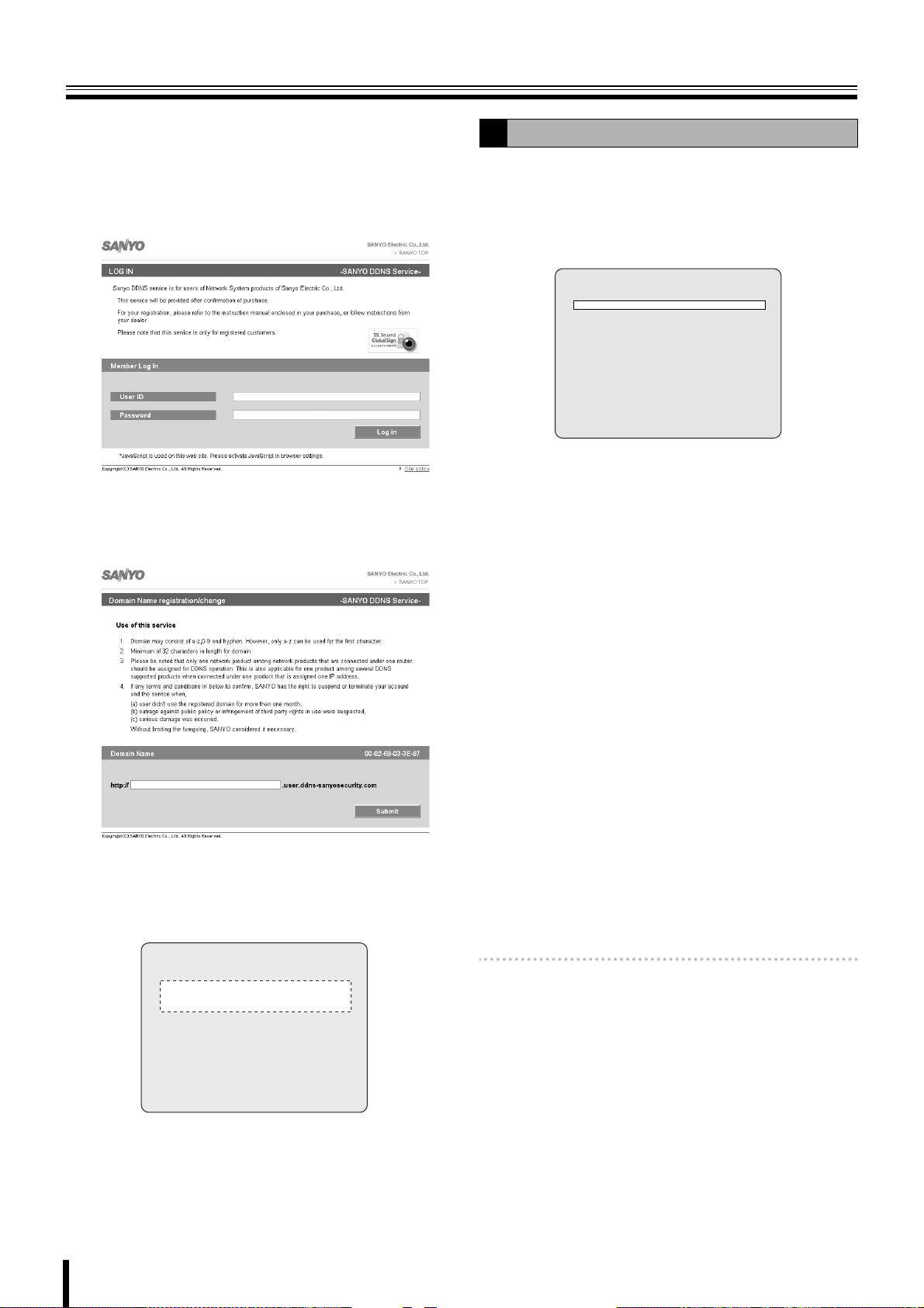
NETWORK settings
Enter the "USER ID" and "PASSWORD" confirmed
5
on the DDNS SERVER SET screen and click the
Login button.
The domain name registration screen is displayed.
Enter the "USER ID" and "PASS WO RD " in capital
letters.
Enter the domain name to be used and click the
6
Submit button.
The domain name is registered to the DDNS server.
Setting the SEND E-MAIL
F
An E-mail can be sent to a specified IP address.
Select "SEND E-MAIL" using the control button
1
({|), select "ON" using the control button (}~)
and press the ENTER button.
The SEND E-MAIL screen is displayed.
SEND E-MAIL
IP NOTIFICATION OFF
EVENT ALARM OFF
MAIL TO
MAIL SERVER
USER
PASSWORD
MAIL FROM
•ON: Enable the sending e-mail function
•OFF: Disable the sending e-mail function
Select the following item using the control button
2
({|) and select the setting using the control
button (}~).
• IP NOTIFICATION:
ON: Does not send a notification E-mail even when
an event alarm is triggered.
OFF: Does not send an E-mail
Return to the DDNS SERVER SET screen of this
7
unit and enter the registered domain name.
Select the input location using the control button (}~)
and select a character using the control button ({|).
DDNS SERVER SET
- - - - - - - - - - - - - - - -
- - - - - - - - - - - - - - - -
USER ID XX-XX-XX-XX-XX-XX
PASSWORD XXXX-XXXX-XXXX
LOG ready
• EVENT ALARM:
OFF: Does not send a notification E-mail even when
an event alarm is triggered.
ALARM:
A notification e-mail is sent when ALARM
recording is triggered by the sensor connected to
the external alarm input terminal (ALARM IN) of
the unit.
MOTION:
A notification e-mail is sent when MOTION
recording is triggered by a movement detected by
the motion sensor built into the unit.
ALL:
A notification e-mail is sent when a recording is
triggered either by an external alarm or the
built-in motion sensor.
Memo: EVENT ALARM requires setting of ALARM-SET.
(P32)
Select the following item using the control button
3
({|) and set the information, such as the E-mail
address, using the control button ({|}~).
Pressing the EXIT/STOP button returns the screen to
the SEND E-MAIL screen.
Press the ENTER button.
8
The DDNS settings complete, the screen returns to the
NETWORK screen.
45
Page 53

NETWORK settings
F
•MAIL TO
To set the destination mail address.
Example:
• MAIL SERVER
Sets the mail server name, as well as the USER and
PASSWORD.
Example:
MAIL TO
@sanyo.com
- - - - - - - - - - - - - -
- - - - - - - - - - - - - -
- - - - - - - - - - - -
MAIL SERVER
mailserver12
- - - - - - - - - - - - - -
- - - - - - - - - - - - - -
Setting the NTP SET
G
Allows synchronizing the time using an internet or LAN NTP
server.
Select "NTP SET" using the control button ({|),
1
select "ON" using the control button (}~) and
press the ENTER button.
The NTP SET screen is displayed.
NTP SET
NTP SERVER ADDRESS1 0.0.0.0.
NTP SERVER ADDRESS2 0.0.0.0.
TIME ZONE GMT +9:00
TIME TO SYNCHRONIZE 01:00
•ON: Use NTP server to adjust time
•OFF: NTP server not used for adjusting time
Select the following item using the control button
2
({|) and press the ENTER button.
Set the NTP server address using the control buttons
({|}~) and press the ENTER button.
• NTP SERVER ADDRESS1
• NTP SERVER ADDRESS2
USER: To set the connection user ID for the mail
server.
PASSWORD: To set the connection password for
the mail server.
Example:
USER
23456
- - - - - - - - - - - - - -
- - - - - -
PASSWORD
20060915
- - - - - - - - - - - - - -
- - - - - -
• MAIL FROM
To set the mail address sent to the destination host.
Example:
MAIL FROM
1 1 1@ABC.com
- - - - - - - - - - - - - -
- - - - - - - - - - - - - -
- - - - - - - - - - - -
Select "TIMEZONE" using the control button ({|)
3
and the time zone using the control button (}~).
Selections: GMT –1:00 to –12:00, 0:00 to 13:00
Select "TIME TO SYNCHRONIZE" using the control
4
button ({|) and the time to synchronize using the
control button (}~).
Selections: 00, 01, 02 - 23
Press the EXIT/STOP button to return to the
NETWORK settings screen.
Press the EXIT/STOP button twice.
4
The screen returns to the NETWORK screen and then
press the EXIT/STOP button again.
46
Page 54

HDD SET settings
Press the MENU button and input the password.
The MAIN MENU is displayed, select "HDD SET" using the
control button ({|}~).
MAIN MENU
RECORDLIVE SYSTEM
HDD SETNETWORK SERVICE
HDD SET
OVERWRITE ON
FORAMT
AUTO DELETE OFF
AUTO DELETE DAYS 30 DAYS
Setting the OVERWRITE
A
Allows continuing recording and overwriting old videos once
the hard disk capacity is full.
When OVERWRITE is set to ON, save required videos to
an external memory device. (P26)
Select "OVERWRITE" using the control button ({|) and
select a setting using the control button (}~).
ON: When the capacity becomes full, former data is
overwritten and the recording continues
OFF: When the capacity becomes full the recording stops
FORMAT settings
B
Initializes the internal hard disk.
All the videos are lost. Before formatting, save required
videos to an external memory device. (P26)
Select "FORMAT" using the control button ({|)
1
and press the ENTER button.
The FORMAT screen is displayed.
Select "CONFIRM" using the control button (}~)
2
and press the ENTER button.
Formatting starts.
Once formatting is complete, the unit restarts and
returns to live videos.
HDD SET
OVERWRITE ON
FORAMT
AUTO DELETE OFF
AUTO DELETE DAYS 30 DAYS
FORMAT
CANCEL CONFIRM
47
Page 55

HDD SET settings
Setting the auto delete function
C
Allows the user to set the storage period for the recording
data.
Once the storage period is expired the data is automatically
deleted.
Select "AUTO DELETE" using the control button
1
({|) and select a setting using the control button
(}~).
ON: The auto delete function is enabled
OFF: The auto delete function is disabled
HDD SET
OVERWRITE ON
FORAMT
AUTO DELETE OFF
AUTO DELETE DAYS 30 DAYS
Select "AUTO DELETE DAYS" using the control
2
button ({|) and set the storage period using the
control button (}~).
If AUTO DELETE is set to "ON", set a recording data
storage period.
Selection: 2/3/4 ... 60DAYS
The recording data beyond the set period cannot be
played back.
48
Page 56

SERVICE settings
Press the MENU button and input the ADMIN password.
The MAIN MENU is displayed, select "SERVICE" using the
control button ({|}~).
MAIN MENU
RECORDLIVE SYSTEM
HDD SETNETWORK SERVICE
SERVICE
SAVE SETUP TO A USB
LOAD SETUP FROM A USB
DISK INFO
Setting the SAVE SETUP TO A USB
A
Saving the menu settings of this unit to a device, such as a
USB memory.
Connect the USB memory to the USB terminal.
1
Select "SAVE SETUP TO A USB" using the control
2
button ({|) and press the ENTER button.
The confirmation screen is displayed.
Select "CONFIRM" using the control button (}~)
3
and press the ENTER button.
The message "SAVING" is displayed and saving starts.
Once saving is complete the SERVICE screen is
displayed.
Setting the LOAD SETUP FROM A USB
B
Allows to call up the menu settings of this unit saved on such
a device as USB memory onto this unit or onto a device of
identical model.
Connecting the USB memory containing the menu
1
settings to the USB terminal.
USB memory
Select "LOAD SETUP FROM A USB" using the
2
control button ({|) and press the ENTER button.
The confirmation screen is displayed.
Select "CONFIRM" using the control button (}~)
3
and press the ENTER button.
The message "LOADING" is displayed and loading
starts. Once loading is complete, the unit restarts and
returns to live videos.
Displays the hard disk information
C
Select "DISK INFO" using the control button ({|) and
press the ENTER button.
The following data is displayed on the DISK INFO screen.
• Total capacity of the hard disk
• Remaining capacity of the hard disk
• Date and time of first recording
• Date and time of last recording
DISK INFO
hda size = 500GB remain=375GB
hda start time:2009.04.18.15:00:00
hda last time:2009.04.24.18:28:45
49
Page 57

Operations using the Network
This unit can be operated from a PC screen by using the supplied network operation software "Sanyo DVR Utility 2000S".
Prior to performing network operations make the following preparations.
Connection and settings
• Network connection:
Connect this unit and the PC using a LAN or Internet
connection. (P5)
• Network settings:
Set the network connection settings on the NETWORK
screen of this unit. (P42)
• The IP address and other settings on the PC must be
appropriate for the connection.
• The maximum number of PCs that can be connected
to one DVR is 4.
Operating environment
•CPU: Intel Pentium4 1.2 GHz or higher
• Memory: Windows VISTA: Minimum 512 MB
(1 GB or higher recommended)
Windows XP: Minimum 256 MB
(512 MB or higher recommended)
•VGA: 16 MB (64 MB recommended)
• Resolution: 1024 × 768
• Disk capacity: 10 MB
(More than 2.1GB when using Sanyo
recording software)
• Operating System:
Windows VISTA,
Windows XP Professional SP2/Windows XP Home
Direct X: Direct X 8.1 or above
Installing "Sanyo DVR Utility 2000S"
Install using the interactive screen.
Insert the supplied CD-ROM in the CD drive and
1
double-click "Sanyo Client.exe".
The installer runs.
Confirm the installation destination folder on the
2
"Choose Destination Location" screen and click
[Next].
To change the installation destination folder, click
[Browse] and select a folder.
50
Page 58

Operations using the Network
To uninstall the software
Select the setup type on the [Setup Type] screen
3
and click [Next].
• In general, select "Typi cal". Depending on the
performance of the PC the program may not
operate. In that case, re-install "Light".
Confirm the program folder in the "Select Program
4
Folder" screen and click [Next].
To install to a different program folder, input the folder
name in the box directly or select a folder from the
[Existing Folders] list.
Specify "SANYO DVR Utility 2000S" in the control panel
[Add or Remove Programs] and uninstall.
The software starts installing.
5
The progress of the installation is displayed on the
"Setup Status" screen.
Installation is complete.
6
Once the installation is complete, the "DVR Utility
2000S" shortcut icon is displayed on the desktop.
Double-click this icon to start the software.
51
Page 59

Connecting to this unit
To start this software, double-click the desktop shortcut icon ( ), the main screen is displayed. When connecting a camera to
this unit following the procedure below, the camera live video is displayed.
b Connecting for the first time
Click the connect button on the operation panel.
1
The connection dialog [Connect] is displayed.
☞ In DSR-2108, the multi-screen switch button
displays a multi-8 screen.
Input information such as the address information
2
and settings required for the connection.
b Disconnecting
Once connected, the connect button on the operation panel
changes to the disconnect button.
Clicking this button disconnects the connection with this unit
and the displayed video disappears.
☞ In DSR-2108, the multi-screen switch button
displays a multi-8 screen.
b When there are several connections
The connection information used with this unit is displayed at
once under the site name in the "---Select Site---" pull down
menu.
To change the connection destination, select Site Name in the
pull down menu and click. The present connection is
disconnected and the specified site is automatically
connected.
•Site Name:
Set up an administrative designation for this unit.
• IP Address/Port No.:
Input the IP address and PORT number set on the
NETWORK screen of this unit.
When using DDNS, input the set domain name into
"IP Address".
Apart from the port that has been set (e.g., 5445), the port
number plus 1 (e.g., 5446) and the port number plus 10
(e.g., 5455) are used.
•Protocol:
Select the protocol (TCP/UDP).
• Password:
Input the network password set on the SYSTEM
screen of this unit.
This unit cannot be connected to the network if the
[CLIENT ACCESS] on the NETWORK screen is not set to
"ON". (P42)
Click [OK] on the dialog [Connect].
3
The camera connects to this unit and the live video of
the camera is displayed on the main screen.
Memo: • To change the connection destination using the
connection button, disconnect the present
connection using the disconnect button and perform
the connection operations again.
• Editing of the registered connection information
such as additions changes or deletions may be
performed under "Site" in the set up menu.
52
Page 60

Main screen structure and function of each part
4
When connected to this unit, the live video of the camera is displayed on the main screen.
3
1
12
34
2
3
2
1
(The example shown is a multi-16 screen display.)
Video display area
1
Displays live video or playback video.
<Screen display method>
Can be switched using the operation button on the screen.
(P55)
• Single-screen • Quad-screen
• Multi-screen (multi-9 screen / multi-16 screen)
• Sequence (camera switch) display
• Full-screen display
☞ In DSR-2108, the only available multi-screen is multi-8
screen.
<Camera information>
The following camera information is displayed on each
camera video.
1 (Top left):
• Camera channel (CH1 - 16)
• Camera designation
To change the camera designation, go to the camera
designation settings (Site) screen in the set up menu.
(P63)
(When no camera is connected to the channel, the
message "No Camera" is displayed.)
☞ In DSR-2108, CH1 - CH8.
2 (Top right):
M: MOTION recording in progress (P17)
A: ALARM recording in progress (P18)
3 (Bottom right):
R: Recording in progress
4 (Bottom left):
A: Alarm output in progress (P54)
Memo: Video is shown in the same channel as the alarm
output terminal number.
Information display area
2
The following information is displayed.
1 Shows the used capacity of the hard disk of this unit
2 Communication bit rate and frame rate
To display, set in the set up menu in the general setting
screen. (P62)
3 Date and time information
For live video: Current date and time
For playback video: Recorded date and time
Operation panel (P54)
3
The view operation buttons are arranged on the panel.
Log window
4
The operation history is displayed as a list.
Displayed items: Type, Site, Event, Date/Time
Memo: Click [SEARCH] on the operation panel to switch the
screen to search mode. One part of the operation
panel display and one part of the log window display
change. (P59)
53
Page 61

Main screen structure and function of each part
Function of the operation panel
1
2
<16 channels>
3
4
5
6
3 Screen display switch button (P55)
: Switching to quad-screen display
:
Changing the display to a multi screen (multi-16 screen/ multi-9 screen)
: To sequence (automatic camera switch) display
-
: Selecting a channel and switching to single-screen
display
☞ In DSR-2108, only multi-8 screen is available since the number of
available channels is 8.
4 Camera controller (Only for PTZ dome camera)
When clicking the controller button ( / ), the controller display
changes. (P58)
: For Pan/Tilt operations
SW
: For Zoom/Focus operations
5 Audio controller
Adjusts the audio output of live video and playback video.
SW
: The audio is not output
: The audio is output
: Adjusts the output volumeVOLUME
8
9
G
: The display of the icon changes according
SW
to the selection made.
1 Scrolling connected sites (Select Site)
To change the connection destination select
the site name of the connection destination
using the pull down menu.
(Normally the site name of the present
connection destination is displayed.)
2 Connect/Disconnect button
: Displays the [Connect] dialog for
SW
connection (P52)
: Disconnects the connection
7
F
H
6 [SEARCH] button
Switches the main screen to search mode (P59)
7 [CAPTURE] button
Saving images (P57)
8 Recording button (P56)
: Sets recording function to ON (Recording to PC hard disk)
SW
9 Still button (P57)
SW
F Alarm output switch button
G Menu button
H Exit button
: Sets recording function to OFF
: Freezes the live video on PC
: Unfreezes the live video on PC
: Switches the alarm output (ALARM OUT 1) on the back panel
to ON/OFF (A The red button light up when an alarm output is
in progress)
: Displays the set up menu screen (P62)
: Exits the software and closes the screen
54
Page 62

Main screen basic operations
Switching the display mode of the screen
A
Allows you to select the display mode for live and playback
video.
b Single-screen display
Click the channel selection button on the operation panel or
select one screen and double-click.
The video of the specified camera is displayed in
single-screen.
Memo: Double-clicking on a single-screen display returns the
previous screen display.
b Quad-screen display
Click the quad-screen display button on the operation panel.
The video of the cameras connected to this unit is displayed
on quad-screen.
b Multi-screen display
Click the multi-screen display on the operation panel.
The video of the cameras connected to this unit is displayed
on multi-16 screen or multi-9 screen.
☞ In DSR-2108, the only available multi-screen is multi-8
screen.
Memo: Each time the button is clicked the display switches in
turn from the multi-16 screen to the multi-9 screen (2
patterns) video.
01 02
05 06
09 10 11 12
03 04
07
08
12
Memo: Each time the button is clicked the video of the next
four channels is displayed in order of the channel
numbers.
0201
0403
1413
1615
0605
0807
1009
1211
☞ In DSR-2108, the unit of 4 screens, 1 to 4 and 5 to 8,
are displayed in sequence.
13 14 15
01
01
04
04
05
05
07 08 09
07 08 09
10
13
14
01 02
16
16
0302
0302
06
06
1211
15
Memo: <About selecting a camera video>
If a live video is selected (clicked) on the quad-screen
or multi-screen display, a red frame appears around
the live video to indicate that it is selected.
It is necessary to select a camera to perform the
following operation in quad-screen or multi-screen.
• Saving images (P57)
• PTZ dome camera operations (P58)
• Switching the audio output (5 Audio controller: P54)
55
Page 63

Main screen basic operations
A
b Sequence (camera switch) display
Click the sequence button on the operation panel while in
single, quad-screen, or multi-9 screen display.
The video is displayed in sequence in the order of the channel
numbers in the present selected display layout.
(Multi-9 screen sequence is available in DSR-2116 only.)
• When using quad-screen display
0201
0403
1413
1615
When the button is re-clicked, sequence display stops and
display returns to normal single-screen display.
☞ In DSR-2108, the unit of 4 screens, 1 to 4 and 5 to 8,
are displayed in sequence.
b Full-screen display
Click the maximize button on the extreme right of the title bar.
Displays, such as the operation panel displays, are hidden
and only the video area is maximized and displayed.
0605
0807
1009
1211
Recording live video
B
b Recording method
The present software allows two modes of recording live
video from a camera. Automatic recording setting is also
available.
<Recording mode>
•Always:
Recording is performed when the recording button on the
operation panel is set to ON.
•Event:
When the recording button on the operation panel is set to
ON, recording is on standby and recording is performed
when specified events occur.
<Automatic recording>
When set to automatic recording, the Recording/Stop button
becomes ON as soon as the DVR Utility 2000S is started.
Recording is performed automatically in the selected mode
even without operating the recording button on the operation
panel.
Memo: • Set the automatic recording or select a recording
mode on the recording settings screen in the set up
menu. (P65)
• Network operation video recordings are all saved on
the PC hard disk. Set the save conditions in the disk
settings screen in the set up menu. (P65)
• No changes to the connected site can be performed
while recording using network operations is in
progress.
• Audio is not recorded.
b Switching recording functions
Switch the recording functions to ON/OFF using the recording
button on the operation panel.
Clicking the recording button on the operation
1
panel.
The recording function changes to ON and the button
display switches to stop.
Press the [Esc] button to return from the full-screen to the
standard screen.
The operation panel is not displayed while in full-screen.
Therefore, no operation can be performed except for
switching display by double-clicking the screen.
Setting the recording function to ON allows recording
according to the recording mode.
• In Always mode:
Starts the recording onto PC hard disk
• In Event mode:
Recording is on standby, recording onto PC hard
disk starts when a specified event occurs
To stop the recording function
2
Click the recording button (Stop) on the operation
panel.
• In Always mode: Stops recording
• In Event mode: Cancels recording standby
56
Page 64

Main screen basic operations
Freezing the live video
C
Stops the live video and allows the user to view the live video
as a still image.
Click the still button on the operation panel.
1
The live video changes to still video, the still button
display switches to the unfreeze button.
Pausing the video will also stop the live audio.
To unfreeze the image
2
Click the unfreeze button on the operation panel.
The live video returns to moving video.
The audio is output
D
Audio output is available for live and playback video.
Click the audio button on the operation panel.
1
The audio is output and the button switches to no
output.
Saving images
E
Allows the user to save live video or playback video displayed
on the screen on the PC, as still images.
Selecting the camera video to be saved.
1
When in quad-screen display, select 1 camera video
and click (a red frame surrounds the selected camera)
or double-click to switch to single-screen display.
Click [CAPTURE] on the operation panel.
2
The [Image capture] dialog is displayed.
Set the saving conditions using the dialog.
3
1 Save Path:
The path set in the general settings screen in the set
up menu is displayed. (P62)
2 File Name:
Change the path and input a new path in the box.
3 File Format:
JPEG or BITMAP can be selected.
Adjust the output volume by dragging and dropping
[VOLUME].
To stop the audio output.
2
Click the audio button on the operation panel.
Click [OK] in the [Image capture] dialog.
4
One screen image is saved when [CAPTURE] is
clicked.
57
Page 65

Main screen basic operations
Operating the PTZ dome camera
F
When the PTZ dome camera is connected to this unit, it can
be remotely operated from the PC.
Sets the menu using this unit.
1
Set the PTZ CONTROL settings on the SYSTEM
screen of the menu settings of this unit. (P14)
Displays the live video and specifies the camera to
2
be operated.
When in quad-screen display, select 1 camera video
and click (a red frame surrounds the selected camera)
or double-click to switch to single-screen display.
Operates the camera using the camera controller
3
on the operation panel.
Clicking the controller button ( / ) switches the
controller display.
b For Pan/Tilt operations
: Adjusts the tilt
: Adjusts the pan
: Switches the controller button to Zoom/Focus
operations
b For Zoom/Focus operations
: Adjusts the zoom
: Adjusts the focus
: Switches the controller button to Pan/Tilt operations
58
Page 66

Search mode operations
When clicking [SEARCH] on the operation panel, the screen display switches to search mode. When in search mode, the display
of one part on the operation panel as well as one part of the log window changes. Search and backup operations of video
recorded on this unit or on the PC become available.
1
1
2
3
Function of the operation panel
1
When in search mode, the following operation button is
displayed.
1 Calendar
To specify the date and time of the video to be searched.
2 [LIVE] button
To cancel the search mode and return to the live video.
3 Playback operation button
Plays back the searched video.
: Plays reverse playback / Fast rewinds
The playback speed switches each time the button
is clicked. (x1, x2)
SW
: Fast forwards
: Moves the paused video to the previous frame
: Advances the paused video to the next frame when
: Plays back
: Pauses and displays a still image
The playback speed switches each time the button
is clicked. (x2, x4)
when the button is clicked.
When in playback, rewinds the video by one
minute when the button is clicked.
the button is clicked.
When in playback, forwards the video by one
minute when the button is clicked.
2
(The example shown is a
132
multi-16 screen display.)
Functions of the time scale
2
The scale and backup operation button for the video search
are displayed in place of the log window.
1 Time scale
Moves the slide knob on the scale as the video is played
back.
The playback point moves as the slide knob is dragged
and dropped to the left or to the right or when clicking on
the scale.
2 Display unit
Switches the mark unit of the scale.
• HOUR: One hour X 24 marks
• MINUTE: 5 minutes X 12 marks
3 Backup operation button
• START POINT:
Sets the start point of the video range to be backed up.
• END POINT:
Sets the end point of the video range to be backed up.
• BACK UP:
Executes the backup.
•DVR/PC:
Switches the recorded video search destination (this
unit or PC).
59
Page 67

Search mode operations
Searching and playing recorded video
A
Video recorded on this unit or on a PC can be searched and
played using the date and time.
Select the search destination (DVR/PC).
1
Select whether to search the video recorded on the
DVR (this unit) or the video recorded on the PC.
The search destination can be switched
interchangeably by clicking [DVR/PC] on the time scale
panel.
The search destination can be confirmed by looking at
the button display.
•DVR:
Searches the video recorded on the DVR (this unit)
•PC:
Searches the video recorded on the PC
Click and specify the recorded date of the video to
2
be searched on the calendar.
If a recorded video is available on the selected date, the
date is displayed in red.
Specify the playback start point.
4
Drag and drop the slide knob of the time scale and
move it to the playback start point.
Playback start point
Click the playback button (1).
5
The video starts playing.
During the playback, the playback operation buttons
allow such operations as fast forward, pause, and
advance to the next frame. (P59)
1
2
Clicking / , switches the calendar display to the
previous/next month.
Confirms the time slot with recorded video using
3
the time scale.
A green line is displayed above the scale if a recorded
video is available.
Recorded part
Memo: Switching the display unit of the scale from [HOUR]
to [MINUTE] allows the user to further narrow down
the time slot with recorded video.
Memo: • If no recorded video is available at the specified
playback start point, the unit jumps to the next
available recorded video and starts playing.
• As in the case of live video, the screen display
mode can be switched using the operation panel
buttons. (P55)
• Playback via network is not available while playing
back with the unit.
To stop playback and return to live video.
6
Click [LIVE] (2) on the operation panel.
Switches to the live video and returns the displays,
such as the operation panel display, to standard mode.
60
Page 68

Search mode operations
Backing up DVR recorded video
B
DVR (this unit) recorded video can be backed up on the hard
disk of a PC in AVI format.
Search the recorded video by following the procedure below,
specify the video range to be backed up and execute a back
up.
Refer to steps 1-3 of "Searching and playing recorded
video (P60)".
Specify the search destination (DVR/PC).
1
Set to "DVR".
Click the calendar and specify the date of the video
2
to be searched.
Confirms the time slot with recorded video using
3
the time scale.
Specify the backup start point.
4
Move the slide knob of the time scale to the start point
and click [START POINT].
Specify the backup end point.
5
Move the slide knob of the time scale to the end point
and click [END POINT].
A dark green line is displayed on the specified video
range.
Click [START POINT]Click [START POINT]
Click [END POINT]
Memo: • To undo the specified video range, re-click [START
POINT].
• If the specified video range is too short, it may be
cancelled when [BACK UP] is clicked. In that case,
specify a longer video range and click [BACK UP],
then adjust it using the “AVI Backup” dialog.
Click [BACKUP].
6
Check the channel selection box of the channels to be
backed up in the "AVI B a c k up " dialog. The video of the
specified channels are backed up sequentially, in the
order of channel numbers.
4
1 Select Channels:
Check the channel selection box of the channel to
be backed up.
However, channels without recorded video are
skipped.
☞ In DSR-2108, CH1 - CH8.
2 Start time/End time:
Can be modified using the spin buttons.
3 File Path:
The path set in the general settings screen in the set
up menu is displayed. (P62)
4 Automatic reconnection:
If the checkbox is checked, backup continues after
reconnecting even if the network gets disconnected
during backup.
If the checkbox is not checked, an error dialog is
displayed. Select whether to continue or cancel.
Click [OK].
7
The specified recorded video range is backed up on the
PC. The backup progress is displayed in the progress
gauge of the dialog.
Memo: • Destination folder name
Input the date information of the first image of the
video.
• Saved file name
(Camera channel number) + time information of the
first image
Example:
[CH1] 08_30_08 = Recorded video from camera 1
at 08h30m08s
• Video is backed up in the AVI format and can be
played using video playback software compatible
with the AVI format such as Windows Media
Player™.
If the video cannot be played with a standard AVI
software, install FFDShow (Codec) from the
supplied CD-ROM. (P27)
Video recorded on the PC can also be backed up by
specifying "PC" as the search destination. However,
there are some limitations, such as the number of
channels that can be backed up at any one time
(limited to 1).
1
2
3
61
Page 69

Setup menu settings
To display the "Setup" screen, click the menu button ( ) on the operation panel. Set the settings concerning the operation
conditions of the DVR (this unit) during connection and the network operations on this screen.
Clicking menu in the [Setup Menu] window on the left of the screen displays the specified menu screen.
General settings (General)
A
Sets functions such as security functions, video data
destination folder and starting automatic connection
functions.
1
5
1 Security Option
When a check is input in the checkbox, a password is
necessary to perform each operation.
• Startup:
Starts the present software
• Shutdown:
Exits the present software
•Setup:
Displays the "Setup" screen
• Live monitoring:
Displays the live video
(Operation of the [LIVE] button on the operation panel)
•Search:
Switches the main screen to search mode
(Operation of the [SEARCH] button on the operation
panel)
2 Password
Clicking the button allows the user to set a [Security
Option] password.
• Old Password:
Input the current password.
•New Password:
Input the new password.
• Confirm Password:
Re-input the new password to confirm the password.
Click [OK] after inputting the password.
2
3
4
3 Save Path
Set the destination folder for still video (Capture) and
backup video (Backup).
4 Miscellaneous
• Automatic reconnection:
If the checkbox is checked, reconnection operations are
performed automatically, after an interval of
approximately 10 seconds, when the network is
temporarily disconnected (NETWORK LOSS).
• Display network statistics:
If the checkbox is checked, the communication bit rate
and frame rate of the network is displayed in the
information display part of the main screen.
• Language:
Allows the user to select the display language.
• Time format:
Allows the selection of the date and time information
display pattern.
☞ Click [OK] once the above settings are complete.
The content of the settings are confirmed and saved.
5 DVR (Remote setup)
Allows the user to perform settings of the DVR unit's menu
from a PC, via network. See P66 - P75.
62
Page 70

Setup menu settings
Camera designation settings (Site)
B
The connection information registered in the "Connect"
dialog at the time of connection is displayed as a list in the
"Site" list.
Allows the user to add, change, delete the registered
information or set a channel name.
1
b Registering the additional DVR (Addition)
Click "Addition".
1
The "Addition" dialog is displayed.
Select the number of channels on the DVR (4/8/16
3
CH) using the "CH Mode".
Click the channel in the "Channels" list and click
4
again on the reversed blue display.
The input box is displayed.
Input the channel name.
5
The specified name is displayed on displays such as
the camera video.
Set a channel name for each channel following the
same procedure.
Click "OK".
6
The "Addition" dialog close and the site is added to the
"Site" list.
b Modify the registered content (Modify)
Click the site to be modified in the "Site" list.
1
The line of the selected site is highlighted in blue.
Click "Modify".
2
The "Modify" dialog is displayed.
Modifying the registered content displayed in the
3
dialog.
Click "OK".
4
The "Modify" dialog shuts down and the "Site" list is
updated.
2
3
4
5
6
Input the information necessary to the connection
2
such as the address.
The input method is the same as the one used for the
"Connect" dialog at the first connection.
•Site Name: Name of the administrator
• IP Address/Port No: The IP address and port
number set in the DVR
•Protocol: TCP/UDP
• Password: The network password set in the DVR
Memo: No channel name is set when connected.
To set channel names use "Modifying registered
content (Modify)".
b Remove a registered site (Remove)
Select the site to be removed in the "Site" list.
1
The line of the selected site is highlighted in blue.
Click "Remove".
2
The "Remove" dialog close and the "Site" is removed
from the "Site" list.
Click [OK] once the above settings are complete.
The content of the settings are confirmed and saved.
63
Page 71

Setup menu settings
5
Event settings (Event)
C
Sets the event management method.
1 Log
Sets the storage location and allowable size of the event
log.
2 Event
Set the saving and display conditions for each event using
the checkbox.
• Log:
Whether it saves it as an event log or not
•Icon:
Whether it displays an icon on the camera video or not
• Event list:
Whether it displays the event on the log window of the
main screen or not
Click [OK] once the above settings are complete.
The content of the settings are confirmed and saved.
1
2
Event log search, view, save (Log View)
D
Event information can be searched and events can be saved
to a PC.
1
4
2
3
Specify the folder to be searched using [Path].
1
Set the start point of the search range in [From].
2
If the checkbox [First] is checked, it is automatically set
to the first date and time in the folder.
Set the end point of the search range in [To].
3
If the checkbox [Last] is checked, it is automatically set
to the newest date and time in the folder.
Click [Find].
4
The event information of the specified range is
displayed as a list in the log list.
To save the displayed log list as text, click [Save].
5
To change the destination folder displayed in [Path],
click [Browse] and select a new destination folder.
Once the above operations are complete, click [OK] and close
the screen.
64
Page 72

Setup menu settings
Record settings (Record)
E
Sets the recording conditions while in network operations.
Recorded video is saved on the hard disk of the PC.
1
2
3
1 Record Condition
Select a recording mode using the radio button.
• Always:
Recording is performed when the recording button on
the operation panel is set to ON.
• Event:
When the recording button on the operation panel is set
to ON, recording is on standby and recording is
performed when specified events occur.
<Automatic recording settings (Auto Record)>
If the checkbox is checked, the recording button on the
operation panel is set to ON and video is automatically
recorded in the selected recording mode only after you
launch the DVR Utility 2000S the next time.
[Auto Record] settings become valid as soon as the unit
has been disconnected and reconnected.
2 Event
If [Record Condition] is set to "Event", set the following
conditions.
Disk settings (Disk)
F
Set the capacity and the drive of the PC where the recorded
video is saved.
1
2
1 Disk Space
Select the drive used for saving and input the allowable
capacity (MB).
2 Disk Full
Select the option once the capacity is exceeded using the
radio button.
• Replace oldest files:
Continues to record and overwrites the previously
recorded video starting with the oldest.
• Stop recording: Stops the recording.
Click [OK] once the above settings are complete.
The content of the settings are confirmed and saved.
Version information (About)
G
The version information of the currently used software can be
confirmed.
<Event types>
• Motion:
When this unit performs a MOTION recording the event
is also recorded on the PC.
•Alarm:
When an alarm signal is input into the external sensor
terminal situated on the back panel of this unit, the
event is recorded on the PC.
<Recording duration>
• Duration (Unit: seconds)
3 Channel
Specify the camera to be recorded using the checkbox.
Memo: Using "All" of the checkbox, the user can check or
uncheck all the cameras.
Click [OK] once the above settings are complete.
The content of the settings are confirmed and saved.
65
Page 73

Remote Setup
The menu settings for the DVR unit can be set from a PC, via network.
Remote Setup operating procedure
A
Click the MENU button on the operation panel.
1
The [Setup] screen is displayed.
Click [DVR] at the lower left of the screen.
2
The [Remote Setup] screen is displayed.
Memo: Remote setup may not be supported depending on
the DVR model. In that case, clicking [DVR] will
display an error message.
Select and click the menu item to set from the tree
3
list.
The specified menu screen is displayed.
Click [Apply] or [OK].
5
The "Remote-Setup Success" message is displayed
on the [Success] dialog and the setting sent to the DVR.
Click [OK] and close the dialog.
12 3
1 Clicking [Apply]:
The [Remote Setup] screen remains displayed even after
the [Success] dialog is closed.
Close the [Remote Setup] screen by clicking [OK] upon
completing all of the remote setup operations.
2 Clicking [OK]:
Closing the [Success] dialog also closes the [Remote
Setup] screen.
3 Clicking [Cancel]:
If a setting value has been changed on the screen, a
dialog confirming whether to save or not the changes is
displayed.
Set the menu item displayed on the screen.
4
Setting is basically the same as with the DVR menu
setting.
Refer to the corresponding pages for details on the
setting items.
Selecting [No] returns the setting to the previous value and
closes the [Remote Setup] screen.
Clicking [Yes] displays the "Remote-Setup Success"
message on the [Success] dialog and sends the settings
to the DVR.
Closing the [Success] dialog also closes the [Remote
Setup] screen.
66
Page 74

Remote Setup
Setting the Display
B
To set the live video display conditions.
b Common settings (General)
These settings apply to all channels.
1
3
5
24
1 OSD
Sets whether to display or not date and time as well as
channel number on the screen.
•ON: Display
• OFF: Do not display
2 Sequence
Setting for automatically switching the displayed video.
Displays the video of the connected cameras on a
single-screen or quad-screen display sequentially, in the
order of channel numbers.
•ON: Automatic sequencing enabled
• OFF: Automatic sequencing disabled
3 Seq-Dwell Time
Sets the interval (1 - 60 SECONDS) for automatically
switching the screens.
b Channel-specific settings
These settings apply to the specified channel only.
1
2
3
1 Channel designation (CH1 - CH16)
☞ In DSR-2108, CH1 - CH8.
2 Display
Sets whether to display or not video from the channel on
the monitor.
•ON: Display
•OFF: Do not display
3 Video image adjustment
• Brightness: Adjusts the brightness.
• Contrast: Adjusts the contrast.
•Hue: Adjusts the hue.
• Saturation: Adjusts the saturation.
4 Event Beep
Setting for sounding an alarm in the event of an alarm.
•ON: Alarm sound enabled
• OFF: Alarm sound disabled
5 OSD Contrast
Adjusts the character contrast on the screen.
67
Page 75

Remote Setup
Setting the Alarm-Set
C
To set the alarm input/output conditions of the alarm input/output terminals.
b Alarm Out
Sets whether to output or not alarm signal from this unit.
•ON: Output enabled
• OFF: Output disabled
b Setting an alarm output terminal
Specify an alarm output terminal number (1 - 4) and set the
alarm output conditions.
1
2
3
4
5
6
1 Alarm Out No.
Specifies the alarm output terminal number (1 - 4).
2 Alarm In
Outputs an alarm signal when the specified external alarm
input terminal receives an input.
Input terminal number
DSR-2116: 1 -16, DSR-2108: 1 - 8
b Setting an alarm input terminal
Specify an alarm input terminal number and set the type.
1
2
1 Alarm In No.
Specifies the alarm input terminal number.
Input terminal number
DSR-2116: 1 -16, DSR-2108: 1 - 8
2 Ty pe
Sets the signal polarity of the specified alarm input
terminal.
• ----: Alarm input detection disabled
• N/O (Normal Open):
Normally open, detects input when closed
• N/C (Normal Close):
Normally closed, detects input when opened
3 Motion ON
Outputs an alarm signal when the specified video input
terminal receives a motion detection signal.
Input terminal number
DSR-2116: 1 -16, DSR-2108: 1 - 8
4 Video Loss On
Outputs an alarm signal when a video loss occurs in the
specified video input terminal.
Input terminal number
DSR-2116: 1 -16, DSR-2108: 1 - 8
5 HDD Error
Sets whether to output or not an alarm signal when a hard
disk error occurs.
•ON: Alarm signal output enabled
• OFF: Alarm signal output disabled
6 Alarm Duration
Sets the duration of the alarm output signal.
(3 - 255 SECONDS)
68
Page 76

Remote Setup
Setting the Monitor2
D
To set the output conditions of the monitor video terminal
(MON2).
1
2
3
4
5
6
1 MON2 Type
Sets the output screen layout of the MON2 terminal.
•FULL: Single-screen output
• QUAD: Quad-screen output
2 MON2 Event
Sets whether to output or not the video of an ALARM
recording to MON2 while it is being recorded.
•ON: Output of ALARM recording video enabled
• OFF: Output of ALARM recording video disabled
<If "Sequence" is set to OFF>
If "MON2 Type" is set to "FULL", sets one channel, and if it is
set to "QUAD", sets 4 channels.
Channel:
DSR-2116: 1- 16, DSR-2108: 1 - 8
<If "Sequence" is set to ON>
Check the channel selection box of the desired channel.
Channel:
DSR-2116: 1- 16, DSR-2108: 1 - 8
3 MON2 Event Dwell Time
Sets the output duration of the ALARM recording video.
(1 - 10 SECONDS) if "MON2 Event" is set to ON.
4 Sequence
Sets whether to automatically switch or not the video
output to MON2 terminal.
•ON: Automatic switch enabled
• OFF: Automatic switch disabled
5 Seq-Dwell Time
Sets the video switching interval (1 - 10 SECONDS) if
"Sequence" is set to ON.
6 Display CH
Sets the channel that outputs video to the MON2 terminal.
69
Page 77

Remote Setup
Setting the Record
E
To set the recording conditions.
b Resolution (Common to all channels)
Sets the resolution for the recordings.
The set value applies to all channels.
• QUAD • FULL • HALF
b Channel-specific settings
These settings apply to the specified channel only.
53
1
2
4
6
7
8
9
F
G
H
J
K
I
1 Channel designation
Channel
DSR-2116: 1 -16, DSR-2108: 1 - 8
2 Frame Rate
Sets the recording rate.
(OFF, NTSC: 1 - 30 ips/PAL: 1 - 25 ips)
3 Quality
Sets the image quality in 5 levels (NETWORK/ECONOMY/
BASIC/NORMAL/FINE).
4 Recording
Sets the recording mode.
• DISABLE: Recording disabled.
• CONTINUOUS: Recording is performed while the DVR
is on.
•BY MOTION:
Recording is performed when the motion sensor built
into this unit detects a movement.
• BY EXT. SENSOR:
Recording is performed when a sensor connected to an
external alarm input terminal (ALARM IN) of this unit
reacts.
• BY SCHEDULE:
Recording is performed at the time slots specified in the
schedule.
5 Timer Set
Sets the schedule for SCHEDULE recording using the
[Schedule] screen. (Refer to P71 for information about the
setting procedure)
6 Motion Sensitivity
Sets the level of detection sensitivity (1 - 9) of the motion
sensor.
The lower the value, the higher the detection sensitivity.
7 Motion Zone
Sets the zone where the motion sensor is active.
A detection frame needs to be set when "PAR T IA L ZO N E"
is selected. (Refer to P71 for information about the setting
procedure)
• FULL ZONE: The motion sensor is active on the whole
screen.
• PARTIAL ZONE: The motion sensor is active in a set
detection frame.
8 Alarm Recording
ALARM recording is performed when an external alarm
signal is input to the specified external alarm input terminal
Input terminal
DSR-2116: -----, 1 -16
DSR-2108: -----, 1 - 8
9 Pre Record
Sets whether to perform or not pre-ALARM recording.
When enabled, recording is started approximately
5 seconds before the internal motion sensor or the
external sensor detector is triggered.
•ON: Pre-ALARM recording enabled
•OFF: Pre-ALARM recording disabled
F Post Event Record
Sets the duration of the ALARM recording
(2 - 30 SECONDS, 1 - 5 MINUTES, 10 MINUTES,
15 MINUTES).
G Audio
Sets whether to perform or not audio recording.
•ON: Recording of audio of live video enabled
•OFF: Recording of audio disabled
H Real Time Frame Rate
Sets the recording rate.
(OFF, NTSC: 1 - 30 ips/PAL: 1 - 25 ips)
I Quality
Sets the image quality for real-time recording in 5 levels
(NETWORK/ECONOMY/BASIC/NORMAL/FINE).
J Post Event Record
Sets the duration of the real-time recording (--, 2 - 30
SECONDS, 1 - 5 MINUTES, 10 MINUTES, 15 MINUTES)
Memo: If "--" is selected, recording is triggered when the
Record/Stop button is pressed or whenever an alarm
input occurs.
K Alarm Recording
Sets the alarm input terminal number that triggers
real-time recording.
Input terminal
DSR-2116: -----, 1 -16
DSR-2108: -----, 1 - 8
70
Page 78

Remote Setup
b Setting the detection frame
Set the zone where the motion sensor will be active.
Set [Motion Zone] to "PARTIAL ZONE".
1
A button is displayed to the right.
Click the button.
2
The screen for setting the detection frame is displayed.
Click (or drag) a grid cell in the desired detection
3
frame.
The sensor is set in the specified frame.
b Setting the SCHEDULE recording
Set the schedule for the SCHEDULE recording.
Click the [Timer Set] button.
1
The [Schedule] screen is displayed.
1
2
Select a recording mode button 1 and click it.
2
The selected recording mode is displayed in colour at
the upper left corner of the schedule 2.
Specify the day of the week and time slot, and click
3
(or drag) the grid cell of the schedule.
Recording is scheduled for the specified time slot.
Multiple recording modes can be combined using the
same procedure.
Click [OK].
4
The contents of the setting are saved and the screen for
setting the detection frame closed.
71
Memo: To schedule the selected recording mode for all of the
time slots (24 hours) of a day, click the button of the
day of the week.
Click [OK].
4
The contents of the setting are saved and the
[Schedule] screen closed.
Page 79

Remote Setup
System settings
F
Settings related to the system and time.
b Setting the System
1
2
3
4
5
6
7
1 DVR ID (P37)
Sets individual designation to DVRs.
2 Admin Password (P38)
This is a password for performing menu settings on the
DVR unit.
Memo: The default value is "1111".
3 User Password (P39)
This setting is used to give controlled operational access
to administrators and general users. The operations with
User Password are limited to search and playback.
Memo: No user password is set by factory default.
4 Network Password (P39)
This password is for limiting the access to the network.
Memo: The default value is "1111".
5 Date Format (P9)
Sets the date display format.
6 Language (P11)
Sets the display language.
7 Remote Controller (P41)
Allows to set an ID number (1 - 99) on the supplied remote
control for its identification.
b Clock Set
1
2
1 Set Date & Time (P9)
Sets the current date and time.
2 D.S.T./SUMMER TIME (P10)
Sets whether daylight saving is applicable or not.
•OFF: Daylight saving not applicable
• U.S.A.: USA daylight saving time applicable
•EU: EU daylight saving time applicable
Select the GMT Area.
(+00:00 to +05:00)
•OTHER: Allows to set the start and end dates of the
daylight saving period for time zones other
than USA and EU.
(Begin/End)
Memo: A confirmation dialog is displayed when [Apply] (or
[OK]) is clicked if the date and/or time settings have
been changed.
The DVR is restarted and the date and time updated
when [YES] is clicked on the confirmation dialog.
Memo: If set to the default value (0), no ID number is
necessary for performing remote operations.
72
Page 80

Remote Setup
Description
G
This sub menu is accessible from the System settings.
Allows to check information on the DVR such as the version
information.
• H/W Version
• S/W Version
• Storage Size: Hard disk capacity
•IP Address
• MAC Address
•Time Count
• HDD A USE TIME: Master hard disk
• HDD B USE TIME: Slave hard disk (expansion)
Setting the PTZ Control
H
This sub menu is accessible from the System settings.
Allows to set the communication environment for remotely
operating PTZ dome cameras connected to RS485 terminals.
b PTZ Control
1
2
3
4
1 DATA SPEED
Sets the communication speed.
The set value applies to all channels.
2 Camera channel designation
3 Protocol
Sets the protocol type for the specified channel.
When connecting multiple cameras, set the same
protocol for all.
4 Address
Sets the camera ID (0 - 63).
b RS-485
Set when connecting a system controller or cameras using
SANYO protocol.
1
2
1 DATA SPEED
Sets the RS-485 communication speed (2400/4800/9600/
19200).
2 Address
Sets the address (0 - 128) of the RS-485 control terminal.
73
Page 81

Remote Setup
Setting the Network
I
To set information about the DVR network.
The DVR will be forcibly restarted if a value on this
screen is changed.
b Network settings
23
1
4
1 Port
When connecting multiple DVRs to the network, set a
unique port number to each DVR.
2 Client Access
To operate via network, make sure the checkbox is
checked.
3 Band Width Saving
To limit the network bandwidth, check the checkbox.
4 Address settings
Input necessary information depending on the selected
[Network Type].
• If "LAN" is selected:
The address setting mode is manual.
Input IP, Gateway, Subnet Mask, and DNS Server IP.
• If "DHCP" is selected:
The address setting mode is automatic.
Addresses and other information do not need to be set.
b DDNS settings
When using Sanyo's DDNS service, select "SANYO" and
input the registered domain name.
Memo: • Refer to P45 for details on how to register the
domain name.
• When using other company's DDNS service,
contact the dealership where this unit was
purchased or a "Repair Service Center".
• If "ADSL" is selected:
Input the login ID and Password.
74
Page 82

Remote Setup
Setting the Send E-Mail
J
This sub menu is accessible from the Network settings.
This setting is used to automatically send a notification e-mail
to a specified address when an alarm occurs, for example.
The DVR will be forcibly restarted if a value on this
screen is changed.
1
2
3
4
5
6
1 Send E-mail
•ON: E-mail sending function enabled
• OFF: E-mail sending function disabled
2 IP Notification
To send a notification e-mail when the DVR IP address is
changed, check the checkbox.
3 Event Alarm
The alarm event type can be used as condition for sending
notification e-mails.
• OFF (factory default)
Notification e-mail is not sent even if an alarm is
detected.
• ALARM
A notification e-mail is sent when ALARM recording is
triggered by the sensor connected to the external alarm
input terminal (ALARM IN) of the unit.
•MOTION
A notification e-mail is sent when MOTION recording is
triggered by a movement detected by the motion sensor
built into the unit.
•ALL
A notification e-mail is sent when a recording is
triggered either by an external alarm or the built-in
motion sensor.
Setting the NTP
K
Allows synchronizing the time using an internet or LAN NTP
server.
1
2
3
4
5
1 NTP USE
•ON: Synchronize using NTP server
•OFF: Do not synchronize using NTP server
2 NTP Primary Server Address
Input the NTP primary server address.
3 NTP Secondary Server Address
Input the NTP secondary server address.
4 Time Zone
Select the time zone.
(GMT -1:00 to -12:00, GMT 0:00 to 13:00)
5 Interval
Set the time to synchronize.
(01 - 24:00)
Setting the Storage
L
Allows to configure continued recording settings by
overwriting the hard disk and the storage period for the
recording data.
1
2
3
Memo: Alarm notification requires setting of ALARM-SET.
(P32)
4 Mail Address
Input the destination address.
5 Mail Server settings
Input the SMTP server name as well as the user ID and
password.
6 RETURN MAIL ADDRESS
Set the source e-mail address to be notified to the
destination.
75
1 Overwrite
To continue recording by overwriting when the hard disk
becomes full, check the checkbox.
2 Auto Delete
•ON: Auto-delete function enabled
•OFF: Auto-delete function disabled
3 Auto Delete Days
If auto-delete is set to ON, set a recording data storage
period.
(2/3/4 - 60 DAYS)
Page 83

Operations using the Web browser
Supported browsers are Internet Explorer 5.5 SP2 or later. Supported OSs are Windows XP and Vista.
Start the Web browser (Internet Explorer).
1
Input the URL.
2
Input the IP address of the hard disk digital recorder in
the browser's address bar.
Input example:
Input the password in the Web Page Dialog.
3
(Authentication check)
The factory default password is "1111". The password
can be changed in NETWORK PASSWORD in the
SYSTEM settings screen.
b Functions of the main operation panel
1
2
3
64
7
9
H
I
J
M
O
8
F
G
Slide knob
K
L
N
P
5
Click the [Connect] button.
4
Clicking [Cancel] closes the Web browser's screen.
The Web Page Dialog is closed and operation from
5
the Web browser is enabled.
<Main screen>
Operation
panel
Video display area
Log window
1 Live video date and time display
2 [DISCONNECT] button
Closes the Web browser's screen.
3 [SEARCH] button
Switches the screen to search mode. (P77)
4 Single-screen display button
5 Quad-screen display button
Each time the button is clicked, the displayed videos switch
sequentially in units of 4 channels.
6 Multi-9 screen display button
In DSR-2116, each time the button is clicked, the
displayed videos switch sequentially in units of 9 channels.
7 Multi-16 screen display button
In DSR-2116, each time the button is clicked, the
displayed videos switch sequentially in units of 16 or 9
channels (2 patterns).
8 Sequence (camera sequencing) button
Available in single- or quad-screen display.
9 Still button
Freezes the live video displayed on the PC.
F Capture button
Saves to PC a still image from the live video selected by
clicking on it, shown with a red frame around it. (P78)
G Audio ON/OFF button
H Audio volume
To adjust the audio output of live videos, drag and drop the
slide knob.
76
Page 84

Operations using the Web browser
I Tilt Up button J Pan Left button
K Pan Right button L Tilt Down button
M Zoom In button N Focus Near button
O Zoom Out button P Focus Far button
<Search screen>
Operation
panel
Video display area
Time scale panel
b Functions of the search operation panel
1
2
3
5
4
7
6
8
F
9
G
H
I
J
L
K
N
M
P
O
Q
5 Quad-screen display button
Each time the button is clicked, the displayed videos switch
sequentially in units of 4 channels.
6 Multi-9 screen display button
In DSR-2116, each time the button is clicked, the
displayed videos switch sequentially in units of 9 channels.
7 Multi-16 screen display button
In DSR-2116, each time the button is clicked, the
displayed videos switch sequentially in units of 16 or 9
channels (2 patterns).
8 Sequence (camera sequencing) button
Available in single- or quad-screen display.
9 Download button
Saves to PC a moving video from the live video selected
by clicking on it, shown with a red frame around it. (P78)
F Capture button
Saves to PC a still image from the live video selected by
clicking on it, and shown with a red frame around it. (P78)
G Audio ON/OFF button
H Audio volume
To adjust the audio output of a video being played back,
drag and drop the slide knob.
I Play/Pause button
J Stop button
K Fast-forward button
L Skip button
Forwards the video by 1 minute when pressed during
playback.
M Skip Frame button
Moves the video to the next frame when pressed during
pause.
N Rewind button
O Replay button
Rewinds the video by 1 minute when pressed during
playback.
P Replay Frame button
Moves the video to the previous frame when pressed
during pause.
Q Calendar
Specifies the date of the video to be searched.
Select the month using the button. Clicking the
date to be searched turns the background of the date to
gray.
Dates in blue are dates for which there is recording data.
To check for time slots with recording data (green line),
display the channel to be searched using the
button on the time scale panel.
To playback the searched video, using drag and drop,
move the slide knob of the time scale to the time to be
played back and click the Play button.
1 Playback video/Still image date and time display
2 [DISCONNECT] button
Closes the Web browser's screen.
3 [LIVE] button
Switches the screen to live mode.
4 Single-screen display button
77
Slide knob
Page 85

Operations using the Web browser
b Saving still images to the PC
Click the Capture button.
1
The Web Page Dialog is displayed.
1
2
3
Select the [Channel] 2 to be saved.
2
Click the [OK] 3 button.
3
A still image of the selected channel is saved to the
folder specified in [File] 1.
Memo: • The storage location is set in the general settings
screen in the setup menu.
• The Web browser's (IE) Protected Mode must be
turned off.
b Saving moving videos to the PC
Click the Download button.
1
The Web Page Dialog is displayed.
2
1
3
4
5
6
Set the starting time [From] 1 and end time [To] 2
2
of the moving video to be saved.
Check the [Channel] 4 checkbox of the moving
3
video to be saved.
Click the [OK] 6 button.
4
The moving video of the selected channel is saved to
the folder specified in [File] 3.
Memo: • The storage location is set in the general settings
screen in the setup menu.
• If [Automatic reconnection] 5 is checked, backup
continues after reconnecting even if the network
gets disconnected during backup.
• The Web browser's (IE) Protected Mode must be
turned off.
78
Page 86

Part names of the remote control
Batteries for the remote control are not supplied. Use two AAA batteries.
b Inserting batteries in the remote control.
1 Take the battery cover off.
1
REC/STOP ALARM
2
4
6
F
L
H
3
5
9
I
123
456
78
0
ID
MENU
SERCH
PTZ LOCK
QUAD
SEQ
9
10
MARK
COPY
MULTI
EXIT
8
J
M
7
G
K
N
2 Place the batteries and fit the cover.
Note: Make sure the batteries are correctly oriented.
b Operation range
Max. 5 m
30° 30°
1 REC/STOP button
Stops and starts recording of live videos displayed on the
monitor.
2 ALARM button
Switches ALARM OUT to ENABLE/DISABLE.
3 Numeric buttons
Used to input passwords, camera number and ID number.
4 ID button
If a remote control ID number was set, press before
inputting it. (P41)
5 • SKIP button
During settings: Moves the cursor upward.
During playback: Skips the video 1 minute forward.
6
• f button
During settings: Moves the cursor to the left.
During playback: Fast rewinds.
7
• e button
During settings: Moves the cursor to the right.
During playback: Fast forwards.
8 REPLAY
• button
During settings: Moves the cursor downward.
During playback: Skips the video 1 minute backward.
F MENU button
Displays the setting menu screen.
G EXIT button (b)
To exit the settings mode and the menu screen.
H SEARCH button
Activates the recorded videos search mode.
I PTZ button
Activates the operation mode that operates the Pan/Tilt/
Zoom/Focus of PTZ dome cameras.
J LOCK button
Switches security lock to ON/OFF.
K MARK • COPY button
Activates the video saving mode.
L SEQ button
Sequences the videos of the connected cameras.
M QUAD button
Displays the quad-screen.
Each time the button is clicked the video of the next four
channels is displayed in order of the channel numbers.
N MULTI button
Displays a multi-screen.
9 ENTER • c/h button
During settings: Confirms the selected item.
During search: Plays back the selected video.
During playback: Displays a still video.
79
Page 87

Specifications
Signal method Conforms to the NTSC/PAL system
• NTSC: 60 ips
•PAL: 50 ips
Compression method Video: MPEG4, Audio: G.711
Number of pixels NTSC: 704×480, PAL: 704×576
Live display Speed NTSC: 30 ips
Resolution NTSC: 704×480 (FULL)
Split-screen DSR-2116: Single-screen/Quad-screen/Multi-9 screen/Multi-16 screen
Recording Recording speed DSR-2116: Maximum 240 ips (NTSC)/200 ips (PAL)
Resolution NTSC: 704×480 (FULL), 704×240 (HALF), 352×240 (QUAD)
Recording method Real time recording/CONTINUOUS recording/MOTION recording/ALARM recording/
Image quality 5 levels (NETWORK/ECONOMY/BASIC/NORMAL/FINE)
Hard disk Up to a 540 GB HDD, up to two built-in HDDs
Video input terminal 1.0 V(p-p), 75 Ω BNC (DSR-2116: ×16, DSR-2108: ×8)
Video output terminal MAIN: BNC ×1, S terminal ×1, VGA ×1 (MAIN BNC and S terminal are mutually exclusive),
Audio input terminal RCA ×4
Audio output terminal RCA ×1
External alarm input terminal No-voltage make contact (DSR-2116: ×16, DSR-2108: ×8) Refer to P18.
Alarm output terminal Relay (DC 30 V Max 1A, 125 VAC Max 0.5 A) ×4 Refer to P4.
Network terminal Interface: RJ-45 (10Base-T/100Base-TX)
Interface RS485 2-pin ×2
Front USB terminal 1 USB (USB 2.0 only), backup (USB Memory)
Disc drive 1 drive, backup (DVD-R, CD-R/RW)
Remote control IR remote control Up to 99 controllable
Power supply voltage 100 - 240 VAC at 50/60 Hz
Current consumption 100 - 240 VAC: 4A
Allowable ambient temperature Operation: 5°C to 40°C, Storage: -10°C to + 50°C
Allowable ambient humidity 0 - 90 %
Dimensions 432 (W) × 89 (H) × 349 (D) mm (Protrusions excluded)
Weight 7.6 kg (with two HDD)
Please note that specifications and unit exterior design are subject to change without notification.
PAL: 25 ips
PAL: 704×576 (FULL)
DSR-2108: Single-screen/Quad-screen/Multi-8 screen
DSR-2108: Maximum 120 ips (NTSC)/100 ips (PAL)
PAL: 704×576 (FULL), 704×288 (HALF), 352×288 (QUAD)
SCHEDULE recording
MON2: BNC ×1
Protocol: TCP/IP, DHCP, UDP
Software: DVR Utility 2000S
b Dimensions (unit: mm)
432 349
89
☞
Dimensions of DSR-2116 and DSR-2108 are the same.
b DVR ID input display list
AB CD E FGH I J K LMNOPQRST
UVWXYZ[\]^_‘abcdefgh
i j k lmnopqr s t uvwxyz { |
}~ ! "#$%& ’ ( ) *+ , - . / 012
3456789 : ; <=>?@
80
Page 88

Mounting the hard disk (S-ATA)
A hard disk may not be installed at the time of purchase. If no hard disk is installed, consult the dealership where the
unit was purchased for purchase and installation.
Make sure the unit is turned off before installing the hard disk.
Remove the unit's cover.
1
Fix the supplied rubber pads to the supplied HDD
2
mounting bracket. Then fix the hard disk to the
mounting bracket using the supplied screws (A).
Connect the unit's power cable (B) and the supplied
3
S-ATA cable (C) to the hard disk. Then fix the hard
disk to the unit using the supplied HDD fixing
screws (D).
B
DISK A
(HDD 1)
DISK B
(HDD 2)
D
C
B
D
C
HDD 1
HDD 2
A
A
81
Page 89

MEMO
...........................................................................................................................................................................................................
...........................................................................................................................................................................................................
...........................................................................................................................................................................................................
...........................................................................................................................................................................................................
...........................................................................................................................................................................................................
...........................................................................................................................................................................................................
...........................................................................................................................................................................................................
...........................................................................................................................................................................................................
...........................................................................................................................................................................................................
...........................................................................................................................................................................................................
...........................................................................................................................................................................................................
...........................................................................................................................................................................................................
...........................................................................................................................................................................................................
...........................................................................................................................................................................................................
...........................................................................................................................................................................................................
...........................................................................................................................................................................................................
...........................................................................................................................................................................................................
...........................................................................................................................................................................................................
...........................................................................................................................................................................................................
Page 90

MEMO
...........................................................................................................................................................................................................
...........................................................................................................................................................................................................
...........................................................................................................................................................................................................
...........................................................................................................................................................................................................
...........................................................................................................................................................................................................
...........................................................................................................................................................................................................
...........................................................................................................................................................................................................
...........................................................................................................................................................................................................
...........................................................................................................................................................................................................
...........................................................................................................................................................................................................
...........................................................................................................................................................................................................
...........................................................................................................................................................................................................
...........................................................................................................................................................................................................
...........................................................................................................................................................................................................
...........................................................................................................................................................................................................
...........................................................................................................................................................................................................
...........................................................................................................................................................................................................
...........................................................................................................................................................................................................
...........................................................................................................................................................................................................
Page 91

MEMO
...........................................................................................................................................................................................................
...........................................................................................................................................................................................................
...........................................................................................................................................................................................................
...........................................................................................................................................................................................................
...........................................................................................................................................................................................................
...........................................................................................................................................................................................................
...........................................................................................................................................................................................................
...........................................................................................................................................................................................................
...........................................................................................................................................................................................................
...........................................................................................................................................................................................................
...........................................................................................................................................................................................................
...........................................................................................................................................................................................................
...........................................................................................................................................................................................................
...........................................................................................................................................................................................................
...........................................................................................................................................................................................................
...........................................................................................................................................................................................................
...........................................................................................................................................................................................................
...........................................................................................................................................................................................................
...........................................................................................................................................................................................................
Page 92

1AC6P1P4015-L8HBT, L8HBU/XE, US (0609KP-LD)
SANYO Electric Co., Ltd.
Printed in Korea
 Loading...